1
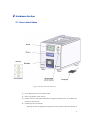
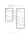
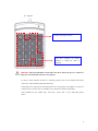
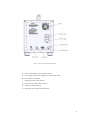
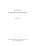
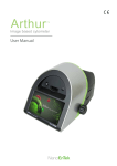
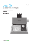
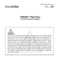
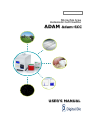
NESMU-ASC-001E (V.0)
Microchip type
Automatic Cell Counter
ADAM Adam-SCC
USER’S MANUAL
Adam series
User’s Manual
All the materials in this manual are protected by Korean and international copyright laws.
This manual may not be reproduced, translated, published or distributed by any means without the permission of the
copyright owner.
ADAM Adam-SCC, User’s Manual
Homepage
: www.digital-bio.com
E-mail
: [email protected]
Developed and Manufactured by NanoEnTek Inc.
12F, Ace High-end Tower, 235-2 Guro-3dong, Guro-gu, Seoul, 152-711, Korea
Tel: +82-2-6220-7911 Fax: +82-2-6220-7721
E-Mail: [email protected]
The information in this manual is described as correctly as possible, but it may be changed without prior consent or
notification.
Copyright © 2007, by NanoEnTek Inc.
All rights reserved. Published in Korea.
Documentation:
NESMU-ASC-001E (V.0) Oct. 10, 2008-10-17
Contents
1. System Components .................................................................................................... 1
2. Hardware Section ......................................................................................................... 3
2-1. Front side of Adam ................................................................................................ 3
2-4. Menu setting........................................................................................................... 8
3. Software Section ........................................................................................................ 10
3-1. Installation of software ........................................................................................ 10
3-2. Port setting with Adam ........................................................................................ 12
3-3. Installation of USB serial driver ......................................................................... 15
3-4. USB to serial driver installation ......................................................................... 15
3-5. Communication port check ................................................................................ 17
3-6. Description of the control software ................................................................... 18
4. Measurements Section .............................................................................................. 20
4-1. Materials & Method .............................................................................................. 21
5. Operating Adam .......................................................................................................... 22
6. Trouble-shooting ........................................................................................................ 28
7. Technical specifications ............................................................................................ 29
1. System Components
When opening the Adam-SCC, you will find the following components in your package:
[Instrument parts]
Adam-SCC main device: 1 unit
Power cord (1.5 m): 1 ea
Paper roll (57.5 mm): 2 roll
Installation CD: 1 ea
USB cable: 1 ea / RS-232C serial cable: 1 ea
Keypad: 1 ea
[Consumable parts]
SCC Kit (Test kit): Reagent & Two or four channel chip
SCC Kit
Adam-SCC (Main device)
SCC Kit
Power cord
Keypad
Fuse
Paper roll
Installation CD
USB cable
Figure1.The components of the Adam-SCC
RS-232C serial cable
The excitation source is a green laser. The emission filter removes all wavelengths except red
fluorescent light. The red fluorescent light from the particles in the sample is focused onto the
detector (CCD camera). Then, the image analysis program counts the red particles to represent the
cell number in the sample.
The Adam’s SCC Kit is intended for easy use in farming or milk truck, 100 μl of stain solutions are
prepared separately in small tubes (CRS-K01: 100 test/pack or CRS-K02: 400 test/pack). One kit is
capable of 100 tests. Each tube has 100 μl reagent of somatic stain solution.
The disposable chip is a significant plastic disposable for loading and detecting of the sample. The
chip loads the volume of 20 μl (for SCC kit CRS-K01, 2 channel chip) and 12 μl (for SCC kit
CRS-K02, 4 channel chip)and with the height of 100 μm. The chip is treated by gas plasma to get a
hydrophilic surface of channels, which drives the sample flow through the channel.
2
2. Hardware Section
2-1. Front side of Adam
LED lamp
Control buttons
Figure 2.The front side of the main device
① LCD: Displays the process and the results
② Door: Chip holder comes out here.
③ Printer: Print the experiment information using the thermal printer. An example of a
printout is shown below.
④ LED lamp & Control buttons:
• Parking: Protect the alignment of stage from external shock when the main device
3
is moved to the other places.
• Start/Run: Performs all procedures of automatic counting or changing the mode
for inputting cow numbers.
• Eject: Ejects the chip holder from the Adam.
Model name
Prints date & time
Farm’s name
Cow’s name
Count result
(T channel)
Count result
(N channel)
Result of 2 channel chip (CRS-K01)
Result of 4 channel chip (CRS-K02)
Figure 3.The example of the result
4
⑤ Keypad:
Key pad: Input the cow number.
Used for selecting the menu
Used after inputting the sample
numbers or setting the menu is
complete.
CAUTION: The keypad should be connected to the device before the power is turned on..
Otherwise, the instrument will not work properly.
In order to check whether the device is working properly, turn on the instrument and press
‘Nm Lock’. The LED lamp should be flickering.
If the lamp is not flickering or the keypad does not work properly, this might be a result of a
connection error. In this case, turn off the power, check the connection and reboot.
The available keys are number keys, ‘Nm Lock’, ‘Enter’ and ‘*’ only. And please ignore
others.
5
Figure 4.The rear side of the main device
① Power switch: Main power ON/OFF control
② Power plug: Connects the Adam power cord to wall outlet
③ Fan: Adam’s cooling fan
④ Keypad port: Key pad connector
⑤ RS-232C port: Serial cable connector
⑥ USB port: USB serial port
⑦ BNC port: CCD camera cable connector
6
2-3. Paper Roll Refill Method
To insert or replace the paper roll of thermal printer see figure shown below. Ensure that the paper
roll is installed in right direction.
▶
▶
Figure 5.The method of paper roll refill
CAUTION: In order to print the results using the thermal printer, check that the
printer cover closed and that the paper roll installed properly. If the printer cover is
open or there is not enough paper roll, the print function would not work.
Paper roll will rotate and come out once the “FEED” button is pressed.
7
2-4. Menu setting
You can set the menu as you press the ‘*’ button on the keypad from the screen for inputting cow
numbers.
12 : 00
>> Input cow number?
T:_
N:
♣ Configuration ♣
Press
‘*’.
1. LCD contrast
2. Chip selection
3. System info.
You can find the setting modes by selecting the number from the Menu.
1)
LCD contrast
Press the number 2 key to adjust the brightness of the LCD screen from the MENU.
[ LCD Contrast ]
♣ Configuration ♣
1. LCD contrast
2. Chip selection
3. System info.
Press
‘1’
Value : 660
[Range : 600~750]
[ LCD Contrast ]
Press
‘Enter’
Value : 660
Value is rerecorded!
[Range : 600~750]
Adjust LCD contrast if the letters do not appear clearly on the screen. Press the ‘Enter’ key after
you input the three digits. The range is from 600 to 750. After pressing the ‘Enter’ key, the screen
will return to the Menu screen automatically.
8
2)
Chip Selection
User can select the 2 kinds of chip type. One is the two channel chip for SCC Kit CRS-K01.
Another is the four channel chip for SCC Kit CRS-K02.
♣ Configuration ♣
1. LCD contrast
2. Chip selection
3. System info.
[ Chip Selection ]
Press
‘1’ or ‘2’
1. 2-channel chip
2. 4-channel chip
Choice: 1
Press the ‘Enter’ key after you input the three digits. After pressing the ‘Enter’ key, the screen will
return to the Menu screen automatically.
3)
System Information
The device versions and date which have been installed in the device can appear when the number
4 key is selected from the MENU. After pressing the ‘Enter’ key, the screen will return to the Menu
screen automatically.
[ System Info. ]
1. Version: SCC V1.0c
2. Date: Nov 19, 07
CORE1: 0.20
CORE2: 0.20
CORE3: 0.20
* Press the ‘*’ key after menu setting. Once inputted, the screen will return to the counting mode
automatically.
9
3. Software Section
3-1. Software Installation
To install the Adam-SCC Report Operation software, follow the directions below. First, insert the
installation CD-ROM into the computer. Then open the file “Setup_Report_v1.0.exe”. The startup dialogue of the software will appear. It is recommended that the “Digital Bio folder> Report” is
located in the default directory of the local hard disk.
When the location has been selected, click “Install” to proceed with the installation. The computer
activates the “Installation of the Software”.
1) Click “Next” to continue.
10
2)
Click “Install” to begin installation to “C:\Program Files\Digital Bio\Report” folder.
3)
Click “Ok” to finish the installation.
4)
If the installation was successful, the report program can be found at Start>All
Program>Report Operation Software>Report.
11
3-2. Port setting with Adam
The fist time using the ADAM monitor or report program, you must confirm the comport settings.
In the desktop window, follow the steps below.
1)
Start>Control Panel>System
2)
Click on “Device Manager”.
3)
Click on “Ports (COM & LPT)”
If the USB serial port is not set to COM5, change it to COM5.
4)
Click the right mouse button on USB Serial Port (COM6) and click on “Properties”.
12
5)
Click on the “Advanced” button.
6)
Change the COM Port Number from COM6 to COM 5.
13
7)
Click the “OK” button.
14
3-3. USB Serial Driver Installation
1)
To install the Adam USB serial driver, follow the directions below. First, insert the
installation CD-ROM into the computer. Then open the file “CDM_Setup.exe”.
2)
Click “Ok” to finish the installation.
3-4. USB to serial driver installation
If experiencing trouble using the serial port (COM1), use the USB to Serial device. (If comport1 in
your PC is not working or does not have a serial port.)
This is an example in how to use the ‘pl-2303’ model. If you use another USB to Serial Device,
you should install suitable device driver file. To find the device driver file, visit the company’s
web site to find additional support.
Install pl-2303 model device driver.
1)
Double click on “PL-2303 Driver Installer.exe”.
2)
Click “Next” to continue.
15
3)
Click “Finish” to complete the installation.
16
3-5. Communication Port Check
1)
Check the connection between the main device and computer via the USB-to-serial line.
2)
Check the communication port and USB serial port.
[START>Control Panel>System>Hardware>Device manager>Port (Com & LPT)].
17
3-6. Description of the Control Software
Report program: Interface to manage and report all results from the main device. All
measurement results are automatically saved on the memory of the main device, excluding
experimental images. The user can also download and delete the individual data from the
memory and export it to Excel (*.xls) format.
CAUTION: Before running the program, check the connection of two cables (RS232C & USB) between the Adam and the PC or desktop. Then check the communication
port on the PC or desktop and refer to Section 3-5.
Figure 6.The main report program
18
1) Port Setting and Application Selection
Using the right button on the mouse click “Port Setting” first, and confirm as bellows:
Port Setting: To set the communication port (Com port COM 1 / USB port COM 5).
SCC: To be used by the database of the main device.
2) Experiment list
The experiment list window consists of the number, date, time, cow number, counting
result and channel type.
After sample test, if the sample result is “Range over”, it describes result as R-O, and the
result is “Check Sample”, it describes result as S-E.
19
3) Function Buttons
Shows the number of experiment data.
Loads the experiment data from the memory of the main device.
Deletes all of the loaded data and memory of the main device.
Transfers the report to Excel format and saves it.
Saved location (Default): “C:\Report\Excel”
File name (Default): Report_Date (Time).xls
4. Measurement Section
SCC Kit (CRS-K01) is composed of Propidium iodide (PI) for counting somatic cells. CRS-K01
can be used without diluting raw milk.
Measuring range of cell density is 0 to 4ⅹ106 cells/ml. Appropriate range of the sample mixture is
5ⅹ104 to 1ⅹ106 cells/ml.
One kit is capable of 100 tests. Each tube has 100 μl reagent of somatic stain solution. Simply add
the same volume of the raw milk sample in the tube then every preparing for experiment end.
Once the experiment is complete the results can be printed through the thermal print. Printed
number indicates cell concentration (ⅹ1000/ml) in each channel.
T: The cell concentration in the T channel of the chip
N: The cell concentration in the N channel of the chip
Store kit box upright and at room temperature. Expiration date of stain solution is written on the
bottom of the kit box (yy-mm-dd). Be sure to check the expiration date before using. Follow the
exact steps detailed in the Instructions for Use section.
1) Add 100 μl of the raw milk sample in the tube.
2) Mix the sample thoroughly by turning the vial upside down 3-5 times.
3) Load 20 μl of the cell sample onto the Chip. Ensure that no bubbles enter the channel.
20
4-1. Material & Method
The following list contains the items needed for somatic cell counting using the Adam.
A raw milk sample
SCC Kit
Pipette and tips
1. The prepared materials ready to be used
Raw Milk
SCC Kit
2. Add 100 μl of the raw milk sample in tube.
..
3. Mix the sample by turning the vial upside down 3-5 times.
4. Load 20 μl (for SCC kit CRS-K01, 2 channel chip) or 12 μl (for SCC kit CRS-K02, 4 channel chip) of the
cell sample onto the Chip. Ensure that no bubbles enter the channel.
N
T
Insert the chip into the chip holder and push the run button.
21
5. Operation of the Adam
1. Check the connection of the main device power cord.
2. Make sure that the main power switch is in the “Ⅰ” (ON) position. (On the rear side of the
main device.)
3. Check initial LCD display of the READY state.
12 : 00
ADAM-SCC
Digital-Bio
>> Input cow number?
T:_
N:
Booting
The screen above is the first display of the ADAM when you turn on the ADAM-MC. It starts to
run system check automatically. And the next screen follows continually if there is no system error.
[ System State ]
ADAM-SCC
Digital-Bio
Booting
Error : 0x00030000
Please let us know if the first screen does not run to the next display automatically or the error
message comes on the screen.
Status of setting menu
12 : 00
>> Input cow number?
T:_
N:
Displays the order status of the performances onto the
ADAM-SCC such as eject, run, parking or insert.
(Status of the Chip Holder)
22
Displays the status for Cell Counting (After you press the run button).
Displays the status of the Chip Holder is being ejected(After you press the eject button).
Displays the status of Chip Holder is being parked(After you press the park button).
Displays the status of Chip Holder is being inserted.
Displays the status when you use the 2 Channel Chip (CRC-T01) (refer to the “2) Chip
Selection” of Menu setting on the page 13).
Displays the status when you use the 4 Channel Chip (refer to the “2) Chip Selection” of Menu
setting on the page 13).
4. 2 Channel Chip (CRC-T01) Cell Counting
1) If no system error is found, Adam is ready to receive the sample numbers. Screen for
inputting the sample numbers will appear and it requires the inputting of three digits. Press
Enter key once the digits have been inputted.
CAUTION: Inserting numbers is not possible with a PC or desktop keyboard. Please
use the provided keypad only.
12 : 00
>> Input cow number?
T : 123
2) Press “
N : 345
, EJECT” button on the main device to eject the chip holder.
3) Insert the Chip loaded with the sample onto the chip holder. Please be careful not to make
bubbles.
[Sample Preparation: Please refer to the 4-1. Material & method section for the detailed
operation.]
T
Insert Direction
N
23
4) Press the “▶, Run” button on the main device.
Automatic Focus will be carried out the first time the device is booted. Shut down the device
properly and the following time the device is turned on, the Auto Focus process will be skipped.
▶
12 : 00
ID
1
T : :123
N:
345
Focusing
▶▶
T : 123
12 : 00
N:
345
Reading
5) After acquiring the image, the chip will be ejected automatically. Then chip can be
removed.
6) The calculated cell number per 1ml will be displayed and printed automatically.
12 : 00
12 : 00
x1024 mL
ID
T : 123
1024
T:
Check sample!
N : 456
512
N:
Over range!
ID
x1024 mL
If the density of sample is over-range, you may see “Check Sample” or “Over Range” message at
display monitor. If you see those messages, please check below list first.
< In case of “Check sample!” >
1.
Check sample contamination, or Chip with dust or other materials.
2.
Check mixture of sample and reagent. It has to be mixed well.
3.
Check test tip whether stained with something.
If you have problems that mentioned above, you will get a result sheet like below.
24
< In case of “Over Range!” >
1. In case of the result of cell-counting is over 4000[X1024mL]
2. Check mixture of sample and agent. It has to be mixed well.
If you have problems that mentioned above, you will get a result sheet like below.
7) For another experiment, repeat the process from steps 4~7.
5. 4 Channel Chip (CRC-T02) Cell Counting
1) Screen for inputting the sample numbers will appear and it requires the inputting of three
digits. Press Enter key once the digits have been inputted.
12 : 00
>> Input cow number?
T1 : 123 N1 : 34_
T2 :
N2 :
2) Press “
, EJECT” button on the main device to eject the chip holder.
3) Insert the Chip loaded with the sample onto the chip holder. Please be careful not to make
bubbles.
[Sample Preparation: Please refer to the 4-1. Material & method section for the detailed
operation.]
T1
T2
N1
N2
Insert Direction
4) Press the “▶, Run” button on the main device.
Automatic Focus will be carried out the first time the device is booted. Shut down the device
25
properly and the following time the device is turned on, the Auto Focus process will be skipped.
▶
▶▶
T1ID: 123
:1
T2 :
N1 : 45
T1 : 123
N1 : 45
N2 :
T2 :
N2 :
Focusing
Reading
5) After acquiring the image, the chip will be ejected automatically. Then chip can be
removed.
6) The calculated cell number per 1ml will be displayed and printed automatically.
ID
T1 : 123
N1 : 45
T2 : 123
N2 : 45
12 : 00
12 : 00
x1024 mL
1024
512
1024
512
ID
x1024 mL
T1 : Check sample!
N1 : 45
512
T2 : 123
1024
N2 : Over range!
If the density of sample is over-range, you may see “Check Sample” or “Over Range” message at
display monitor. If you see those messages, please check below list first.
< In case of “Check sample!” >
1.
Check sample contamination, or Chip with dust or other materials.
2.
Check mixture of sample and agent. It has to be mixed well.
3.
Check test tip whether stained with something.
If you have problems that mentioned above, you will get a result sheet like below.
< In case of “Over Range!” >
26
1. In case of the result of cell-counting is over 4000[X1024mL]
2. Check mixture of sample and agent. It has to be mixed well.
If you have problems that mentioned above, you will get a result sheet like below.
7) For another experiment, repeat the process from steps 4~7.
CAUTION: At low temperature (≤10℃), please warming up the system for 10 min.
27
6. Trouble shootings
1.
2.
3.
4.
ADAM is not working:
①
Check the connection cable and power.
②
Turn on ADAM and check working.
③
Check the COMPORT settings in Section 1 and Section 2.
④
At low temperatures (≤10℃), please warm up the system for 10 minutes before use.
⑤
If you experience any further problems, contact us.
USB to Serial Port is not COM5 in my PC.
①
Check COMPORT as detailed in Section 1 and Section 2.
②
If you experience any further problems, contact us.
My PC does not have a serial port.
①
Use USB to Serial Device as explained in Section 2.
②
If you experience any further problems, contact us.
Please let us know if you see an error message or the following step does not operate properly.
ADAM-SCC
[ System State ]
Digital-Bio
Booting
Error : 0x00030000
28
7. Technical Specifications
• Hardware
Objective lens : 4ⅹ
Laser
: 532 nm
CCD
: 1/3 inch B/W CCD
Display
: 128ⅹ64 LCD Monitor
Printer
: Thermal printer, 57.5(W) mm paper roll
Stage controller
• Dimensions
220(L) ⅹ 350(W) ⅹ 250(H) mm
• Weight
Approximately 10 kg
• Power
AC 115~230 V, 6/3A, 50-60 Hz
• Environment Condition
5 ≤ T ≤ 40 ℃
rH ≤ 80 %
Altitude ≤ 2000 m
• Loading Volume
Prior to analysis, the sample is mixed with a stain solution.
20 μl is recommended for each channel in Two Channel Chip.
• Measuring Time
: About 1 min/test
• Measurement Range
Operational: 5ⅹ104~ 4ⅹ106 cells/㎖
29
• Accessories
Power cord : 1.5 m
Fuse: 250 V.AC 3A
Paper roll: 57.5(W) mm
• Related products
Model No.
Product
Contents
Adam-SCC
Adam
Main device
CRS-K01
SCC Kit
50 pcs Soma Chip (CRC-T01)
100 ul Stain solution 100 ea
(Max. 100 tests/kit)
CRS-K02
SCC Kit
100 pcs Soma Chip (CRC-T02)
100 ul Stain solution 400 ea
(Max. 400 tests/kit)
ADM-001
External video monitor
[Optional]
30
Contact Information
NanoEnTek Inc.
Tel : +82-2-6220-7911
Fax : +82-2-6220-7721
E-Mail : [email protected]
31