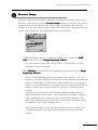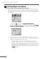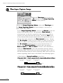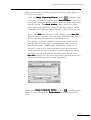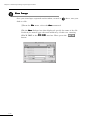
1
Lumina Vision
USER’S MANUAL
Version 1
MITANI CORPOPATION
PLEASE NOTE
(1) This manual, whether in whole or part, may not be reproduced in any form
without the prior written permission of the corporation.
(2) This manual is subject to change in its contents.
(3) This manual has been prepared with full check to make sure of its contents being
free of any error. Notwithstanding this, however, if you find any error, omission
or doubtful point in the contents of the manual, please contact our corporation.
(4) Our corporation shall not be liable for any of the consequences of the use of the
manual, whether direct or indirect, without reference to item (3) above.
\
Macintosh is the registered trademark of Apple Computer, Inc.
\
This Lumina Vision software is based on CodeWarrior (metrowerks, Inc.)
This product contains Stone Table (TM), by Stone Tablet Publishing. All right to Stone
Table (TM) and its documentation are retained by Stone Tablet Publishing, PO Box
12665, Portland OR 97212-0665 USA.
Copyright (C) 1992 – 1999 Stone Tablet Publishing
MITANI CORPORATION
LV0003
Table of Contents
Chapter 1 General Description ................................... 1-1
1. Software ................................................................. 1-1
1.Software
2.Operating
2.
Operating Environment ......................................... 1-2
2.1 Necessary Equipment .........................................................................
.........................................................................1-2
1-2
2.2 Operating System (OS) ........................................................................
........................................................................1-3
1-3
Chapter 2 Check before Power ON ............................. 2-1
1. Checking Product Contents ................................... 2-1
1.Checking
2.Connecting
2.
Connecting Copy Protection Device ...................... 2-1
3.Connecting
3.
Connecting Image Capturing Board/Camera ........ 2-2
Chapter 3 Software Installation ................................. 3-1
1.Setting
1.
Setting up System Software .................................. 3-1
1.1 How to Set up LuminaVision .............................................................
.............................................................3-1
3-1
1.2 How to Set up HASP Driver ...............................................................
...............................................................3-1
3-1
1.3 How to Set up Image Capturing Device Driver .............................
.............................3-2
3-2
1.4 Rebooting the Computer after Driver Setup ..................................
..................................3-2
3-2
Chapter 4 Basic Operation ......................................... 4-1
1. Starting and Exiting .............................................. 4-1
1.Starting
2.Selecting
2.
Selecting Menu Items and Commands .................. 4-2
3.Inputting
3.
Inputting Alphanumeric characters ...................... 4-5
Chapter 5 Image Capturing Procedure ........................ 5-1
1. Standard Image Capturing Flowchart .................. 5-1
1.Standard
2.Set
2.
Set Initial Image Capturing Condition ................. 5-2
3.Set
3.
Set Initial Camera Condition ................................ 5-3
4.Set
4.
Set Camera Focus .................................................. 5-6
5.Preview
5.
Preview Image ....................................................... 5-8
6.Save
6.
Save Image Capturing Condition ........................ 5-10
7.Set
7.
Set Image Region to be Captured ....................... 5-11
I
8. Set Color Balance ................................................ 5-12
8.Set
9.Set
9.
Set View Range .................................................... 5-14
10.Capture
10.
Capture Image ................................................... 5-15
11.Save
11.
Save Image ......................................................... 5-15
Chapter 6 Time-lapse Image Capturing Procedure ....... 5-1
1. Standard Image Capturing Flowchart .................. 5-1
1.Standard
2.Set
2.
Set Initial Image Capturing Condition ................. 5-2
3.Set
3.
Set Initial Camera Condition ................................ 5-3
4.Set
4.
Set Camera Focus .................................................. 5-6
5.Preview
5.
Preview Image ....................................................... 5-9
6.Save
6.
Save Image Capturing Condition ........................ 5-11
7.Set
7.
Set Image Region to be Captured ....................... 5-12
8.Set
8.
Set Color Balance ................................................ 5-12
9.Set
9.
Set View Range .................................................... 5-15
10.Time-lapse
10.
Time-lapse Capture Image ................................ 5-16
11.Save
11.
Save Image ......................................................... 5-18
Chapter 7 Image Analysis Procedure 1 ....................... 6-1
1. Analysis Flowchart ................................................ 6-1
1.Analysis
2.Load
2.
Load Image Data ................................................... 6-2
3.Combine
3.
Combine Image Data for Multicolor Composition 6-2
4.Save
4.
Save Multicolor Composite Image ......................... 6-5
Chapter 8 Image Analysis Procedure 2 ....................... 6-1
1. Analysis Flowchart ................................................ 6-1
1.Analysis
2.Load
2.
Load Image Data ................................................... 6-2
3.Set
3.
Set ROI ................................................................... 6-3
4.Create
4.
Create Time-series Change Graph ........................ 6-5
5.List
5.
List Time-series Change Data .............................. 6-6
6.Save
6.
Save Time-series Change Graph and Data ........... 6-7
II
Chapter 1
General Description
1. Software
2. Operating Environment
Chapter 1 General Description Chapter 1 General Description
Software
The Lumina V
Vision
ision software is a fluorescent image processing software
designed integrating all relevant programs from capturing of fluorescent
image to its analysis. To execute all these programs, the software is provided with commands in plenty, but properly organized in a menu form so
that they can be simply selected and executed using the mouse, making it
very easy to operate. The software is thus designed to allow even beginners to easily proceed with highly sophisticated image analysis on a stepby-step basis in an interactive manner.
In particular, the software can be characterized by the following features:
(1)A screen window of Image Capturing Palette designed to allow
fluorescent image to be easily captured from a camera into the
system for analysis,
(2)A software function available to process monochrome image
16bit and color image 48bit data,
(3)A software function available to process image data for
multicolor composition, and an optionally-available software
function to time-lapse capture image (as an option), and
(4)A system design made to allow use of Macintosh’
Macintosh’ss excellent
user interface.
1-1
Chapter 1 General Description
Operating Environment
2.1 Necessary Equipment
(1)Image capturing board/camera
The software requires the use of a camera designed to capture darkfield image. The software is designed to support Cool SNAP, SenSYS
Series and ORCA Series.
The Cool SNAP and SenSYS Series are provided with image capturing
boards designed for exclusive use with them.
The ORCA Series requires separate arrangement for Snapper (Data
Cell)(Macintosh) as its image capturing board.
For the latest information about the image capturing boards
available for use with this software, refer to “Instructions on
Image Capturing Equipment” provided as a separate volume.
Image capturing equipment
LuminaVision
Image output equipment
1-2
Chapter 1 General Description
(2) Computer
Macintosh (designed with a memory capacity of 64MB or above and a HD
capacity of 6GB or above)
※The software requires the use of a Macintosh computer with a memory
capacity of 128MB or above, if installed with an optional function “Timelapse” image capturing.
(3) Keyboard
(4) Display
(5) Printer
2.2 Operating System (OS)
The software requires the use of Mac OS8.5 or its upgraded version for its
operating system.
1-3
Chapter 2
Check before Power ON
1. Checking Product Contents
2. Connecting Copy Protection Device
3. Connecting Image Capturing Board/Camera
Chapter 2 Check before Power ON
Chapter 2 Check before Power ON
Checking Product Contents
This product contains the following items. When you purchase the product, please check it to make sure that it contains all these items.
①
②
③
④
⑤
LuminaV
ision CD-R
LuminaVision
User ’s Manual
Instructions on Image Capturing Equipment
User Registration Card
Copy Protection Device
1
1
1
1
1
floppy disk
copy
copy
copy
unit
Connecting Copy Protection Device
This software is designed so that even if installed in your computer, it
cannot be executed unless the copy protection device provided as its accessory equipment is connected to the computer’s USB port as illustrated in
the following figure.
◆ Macintosh
2-1
Chapter 2 Check before Power ON
Connecting Image Capturing Board/Camera
The image capturing board to be used should be kept in an anti-static
electric bag before being actually connected to the computer. When taking
the image capturing board out of the bag for its connection to the computer,
hold its card edge, never touching any of its components. When connecting
the image capturing board to the computer, follow the procedure described
in the manual provided with it.
For the latest information about the image capturing boards
available for use with this software, refer to “Instructions on
Image Capturing Equipment” provided as a separate volume.
2-2
Chapter 3
Software Installation
1. Setting up System Software
Chapter 3 Software Installation
Chapter 3 Software Installation
Setting up System Software
1.1 How to Set up LuminaVision
① Close other application if opened on the screen.
LuminaVision
② Set the LuminaV
ision CD-R disk in the drive unit.
ision
LuminaVision
③ Open the CD-R program menu. From the menu, copy the LuminaV
folder onto the desktop screen of your computer using the drag-and-drop
technique.
1.2 How to Set up HASP Driver
This software is designed so that it can only start its operation on your computer after making sure that the copy protection device has been properly
connected to the computer’s HASP. This requires the copy protection key
(HASP) driver to be installed in your computer. The driver installation can
be carried out as follows:
① Set the LuminaV
ision CD-R disk in the drive unit.
LuminaVision
② Open the CD-R program menu. From the menu, copy MacHASPUsbDD
into the system folder
folder’’s function expansion folder
folder..
3-1
Chapter 3 Software Installation
1.3 How to Set up Image Capturing Device Driver
Install your computer with the driver attached to the image capturing board.
The driver installation step can be omitted if the operation of the software
will not involve any control of the image capturing equipment.
If the operation of the software involves any control of the image
capturing equipment, be sure to install the driver in the computer. If the computer is not installed with the driver, you cannot
capture your image from the device into the system.
1.4 Rebooting the Computer after Driver Setup
If the installation of the HASP driver and image capturing device driver is
completed, be sure to reboot the computer, thus allowing it to become ready
for the operation of the software.
3-2
Chapter 4
Basic Operation
1.Starting and Exiting
2.Selecting
2.
Selecting Menu Items and Commands
3.Inputting Alphanumeric Characters
Chapter 4 Basic Operation
Chapter 4 Basic Operation
Starting and Exiting
【Procedure for starting LuminaV
ision
LuminaVision
ision】
①On the desktop screen, open LuminaVision folder.
②Double-click on the LuminaVision application to start it. When the loading
of the application onto the computer is completed, the computer display will
show such a screen as shown in the following figure.
【Procedure for exiting LuminaV
ision
LuminaVision
ision】
You can cause the LuminaVision application to exit from the computer system by selecting command Exit in the File menu. Specifically, the Exit
command can be selected; move the mouse cursor to File on the Menu bar at
the top of the screen. Click on the File menu to pull it down. On the pulldown menu thus displayed, move the mouse cursor to command Exit and
click on it.
4-1
Chapter 4 Basic Operation
Selecting Menu Items and Commands
The LuminaVision software program is designed so that its menu items and
commands can be selected using the mouse in various ways such as “Clicking
(quickly pressing and releasing its left button) and dragging (pressing and
holding down its left button while moving it).
(1)Menu bar
Clicking on one of these items on the Menu bar at its indicated position
causes its corresponding menu to be displayed on the screen.
(2)Menu items
(3)T
ool bar commands
(3)Tool
Clicking on one of these tools on the Tool bar causes its corresponding tool command to be executed.
4-2
Chapter 4 Basic Operation
(4)Dialogue box
Control button
Command button
Pop-up button
①Command buttons
Clicking on any of the command buttons causes its corresponding
command to be executed.
②Option buttons
Option buttons are used for any multiple-choice item such as one
shown above, providing more than one option from which to select
one for its setting.
Clicking on the option button (⃝) for the option you want causes a
black dot to appear inside the circle of the button, turning it into ,
which indicates that that option has been selected.
③Pop-up buttons
When any of the pop-up buttons is selected, it will display more
than one option, from which to select one. In this case, for example, clicking on the Grayscale causes a list of more than one
option to appear, from which you can select one you need by moving the cursor to it and releasing the clicking.
4-3
Chapter 4 Basic Operation
④Check box
A check box (
) is used for any command item that is to be set
activated (selected) or deactivated (unselected) by clicking on the
box to put a check mark in it, turning it into ✓ , or leaving it
unchecked, respectively.
Clicking on the checked box ( ✓ ) causes the selection of its corresponding command to be cleared with the check mark deleted
from it, turning it into
.
Check box
⑤Scroll bar
Appearing in the image window, the scroll bar can be used to
scroll the display of the image in it. Clicking or dragging the
position of the scroll bar allows the image display to be scrolled in
the direction selected. You can also use the box portion of the
scroll bar (
) by dragging it to scroll the image display.
⑥Slider
In a dialogue box requiring input of a value selected from more
than one, a slider appears to let you select the value by dragging
the slider bar (
) left or right to set it at that value.
4-4
Chapter 4 Basic Operation
Inputting Alphanumeric characters
The LuminaVision software is designed to allow any necessary alphanumeric
character input to be made as described below:
(1)Inputting numeric characters
|” to appear at the “I”
Clicking this area causes the cursor “|
position for numeric character input, allowing any numeric
character to be entered from the keyboard with the entered
numeric character appearing at this position.
(2)Inputting alphabetical characters
|” to appear at the “I”
Clicking this area causes the cursor “|
position for alphabetical character input, allowing any alphabetical character to be entered from the keyboard with the
entered alphabetical character appearing at this position.
4-5
Chapter 5
Image Capturing Procedure
1.Standard Image Capturing Flowchart
1.Standard
2.Set
2.
Set Initial Image Capturing Condition
3.Set Initial Camera Condition
4.Set Camera Focus
5.Preview Image
6.Save Image Capturing Condition
7.Set Image Region to be Captured
8.Set Color Balance
9.Set View Range
10. Capture Image
11. Save Image
Chapter 5 Image Capturing Procedure Chapter 5 Image Capturing Procedure
Standard Image Capturing Flowchart
In this chapter, let’s operate the LuminaVision program actually by displaying the Image Capturing Palette window on the screen to learn how to use a
fluorescence camera to capture a piece of image into the system according to
the following flowchart:
5-1
Chapter 5 Image Capturing Procedure
Set Initial Image Capturing Condition
When you use a fluorescence camera to capture an image into the system,
display the Set initial image capturing condition dialogue box on the screen
as shown in the following figure. In the dialogue box, set the image capturing
method by selecting a camera according to the procedure described below:
① From the tool bar, select
turing condition dialogue box.
to display the Set initial image cap-
② In the dialogue box, select the Capture image tab and set Method by
selecting Camera
Camera.
③ In the Cameras or capture cards available for use with the system
group box, select the camera or capture card connected to the computer.
④ Select the
correct.
button after confirmation that all the setting is
⑤ Move the cursor to the tool bar and click on
to display the
Image Capturing Palette as shown on the next page.
The camera selection in the Set initial image capturing condition dialogue box
does not involve its physical access to the camera connected to the computer, but
no more than its software setting. Therefore, in the Cameras or capture cards
available for use with the system group box, you can select ORCA Series even if
you have CoolSNAP, SenSYS Series connected to the computer, and the reverse is
also true. Make sure that your camera selection is correct in this respect.
5-2
Chapter 5 Image Capturing Procedure
Set Initial Camera Condition
Palette you can set the initial camera condition
In the Image Capturing Palette,
such as the black level, maximum/minimum exposure time, auto exposure
condition and use/disuse of the shutter in focus setting mode.
① From the Image Capturing Palette,
to display the Set
Palette select
Initial Camera Condition as shown in the following figure:
② Set the black level of the camera.
Any camera captures some image if its lens opening is minimized.
Therefore, the system must be set so as to exclude any image data
captured from the camera with its lens opening minimized from the
image data captured from it under normal condition for analysis. Such
setting of the system can be achieved by capturing image data from the
camera with its lens opening minimized and setting it as black according to the procedure described below.
In the Set initial camera condition dialogue box, activate the Calibration check box and select the Measure button. Then, minimize the
camera’s lens opening for light shutoff.
If All preparations for the camera’s black level setting are completed,
follow the message displayed on the screen to click on the
button.
5-3
Chapter 5 Image Capturing Procedure
③ Return the camera’s lens to its original opening and follow the message displayed on the screen as shown in the following figure to click on
the
button .
* The execution of steps ② and ③ mentioned above completes the
setting of the camera’s black level. Be sure to perform this process if
you use a camera to capture image data into the system, irrespective
of whether the data is a color or monochrome image.
④ Set the maximum/minimum exposure time of the camera.
This setting can be made using the Exposure time group box in the
Set initial camera condition dialogue box to enter your desired
※This setting is effective only for the CoolSNAP/SenSYS Series. In
the case of the ORCA Series, the maximum/minimum exposure time
is to be set in three modes, each of which has a certain allowable
range for the exposure time setting.
⑤ Set the camera lens exposure time determining condition for the auto
exposure mode, in which the system can automatically determine the
exposure time while capturing image data from the camera. (Refer to
Section 5 “Preview Image”.)
This setting can be made using the Auto exposure condition group
box in the Set initial camera condition dialogue box to enter 0 to
4095 in the Level text box as a level for the exposure time determining condition. This level can be regarded as the intensity of the
image data to be captured from the camera.
The Upper limit text box in the Auto exposure condition group box is used
to enter the upper limit on the exposure time in the auto exposure mode.
When, in the Image Capturing Palette
Palette, the Select auto exposure for
image capturing check box is activated to perform image capturing
operation in the auto exposure mode, the system will increase the
exposure time from the Min. value to the value set in the Upper
limit text box to determine the exposure time, at which the maximum intensity of the image data exceeds the value set in the Level
text box, as the exposure time in the auto exposure mode.
5-4
Chapter 5 Image Capturing Procedure
For example, when you capture a 12bit monochrome image (which
ranges in intensity from 0 to 1023) with 800 entered in the Level text
box, the system will determine the exposure time, at which the
maximum intensity of the image data first exceeds 800, as the exposure time in the auto exposure mode.
⑥ Set whether to use the shutter in the focus setting mode by activating or deactivating the Use shutter in focus setting mode check box.
This setting is effective only for CoolSNAP/SenSYS Series.
5-5
Chapter 5 Image Capturing Procedure
Set Camera Focus
When you capture a fluorescent image into the system, you are required to
focus your camera on the image in a short time because it may undergo quick
discoloration. The LuminaVision software is designed to set the camera focus
on an image to be captured into the system, always using its monochrome
image data with a binning of 2×2.
Binning is a technique by which to allow a camera to capture an image by
using more than one pixel of the camera for one pixel of the image to increase
its sensitivity. With a binning of 2×2, for example, the camera can capture
the image with the image’s pixel size reduced to 1/4 of the camera’s pixel
resolution, thereby shortening the time required for transmission of the
image data from the camera to the personal computer. The binning is also
effective in increasing the sensitivity of the image to light, allowing its exposure time to be shortened with resultant control of its discoloration that may
otherwise occur during its focus setting process.
①Set your fluorescent sample in a microscope.
②From the tool bar, select
to display the Image Capturing
Palette as shown in the following figure.
Palette set No. of bits to that of the camera
③In the Image Capturing Palette,
connected to the computer.
5-6
Chapter 5 Image Capturing Procedure
④Set Exposure time and select the
button. When this button is
selected, the system will cause the camera to start capturing the image,
displaying the captured image data in the image window continuously.
You can change the exposure time, even while the system is operating for continuous display of the captured image data in the image
window. The exposure time can be shortened by shifting the slider
bar leftward and lengthened by shifting it rightward. If the image
is dark, lengthen the exposure time. Conversely, if the image is too
bright, shorten the exposure time.
※When you use CoolSNAP/SenSYS series, you can select whether or
not to output the signal to actuate the shutter in the focus setting mode
by activating or deactivating the Use shutter in focus setting mode
check box in the Set initial camera condition dialogue box.
⑤ Adjust the Z stage to optimize the camera focus on the image.
⑥When the camera focus setting is completed, select
again to stop
the image capturing operation.
*When the ORCA Series is selected, the exposure time can be set in
three modes as described in the following table. The camera focus can
only be set with a binning of 2×2.
ORCA exposure time setting modes
Mode
Description
Normal
Fixed at 55.6mSEC, the exposure time cannot be changed.
Shutter mode
With the operation of the electronic shutter, the exposure and image loading are repeated.
The exposure time can be set in the following ranges depending on the pinning.
No pinning
Exposure
Pinning 2×2
Exposure
Pinning 4×4
Exposure
Exposure
Frame blanking
time = 132.1μSEC+(n-1)×106.9μSEC(n=1-1039)
time = 132.1μSEC+(n-1)×106.9μSEC(n=1-519)
time = 132.07μSEC, Exposure time = 238.95μSEC
time = 238.95μSEC+(n-2)×118.27μSEC(n=3-260)
With frame blanking, the exposure and image loading are repeated. The exposure time can
be set in the following ranges depending on the pinning.
No pinning
Exposure time = n×111.2mSEC(n=1-90)
Pinning 2×2
Exposure time = n×55.6mSEC(n=1-180)
Pinning 4×4
Exposure time = n×31.5mSEC(n=1-325)
5-7
Chapter 5 Image Capturing Procedure
Preview Image
After the camera focus setting is completed, making sure that the camera focus
has been set properly, select the Preview image function to finalize the camera
condition such as the exposure time and pinning. In addition, this function allows
you to preview a color image captured into the system. This function can be also
used to make the final adjustment of the camera focus.
①When the image data to be captured is RGB color, activate the RGB color
check box in the Image Capturing Palette
Palette.
*If your camera connected to the system is a monochrome one, this check
box cannot be selected.
②Set Pinning by pressing its corresponding pop-up button in the Image
Palette.
Capturing Palette
You can set the pinning by selection from the three choices – No, 2×2 and
4×4, in which order the sensitivity increases, allowing the exposure time
to be shortened. It is therefore recommended that if your image is subject
to severe discoloration in a short time, the binning should be set larger to
allow it to be captured into the system in a time as short as possible.
It should be noted, however, that a larger pinning setting results in reduced resolution of the image – the resolution of the image captured with a
pinning of 2×2 is reduced to 1/2 of that with no pinning. The same is true
when the image resolution achieved with a pinning of 2×2 is compared to
that with a pinning of 4×4.
*The pinning setting varies with the specification of the camera you use
with the system. Carefully read the instruction manual for the camera.
5-8
Chapter 5 Image Capturing Procedure
③ Set Exposure time and select
in the Image Capturing Palette
Palette.
When this button is selected, the system will cause the camera to start
capturing the image, displaying the captured image data in the image
window continuously. You can change the exposure time, even while the
system is operating for continuous display of the captured image data in
the image window. The exposure time can be shortened by shifting the
slider bar leftward and lengthened by shifting it rightward. If the image
is dark, lengthen the exposure time. Conversely, if the image is too bright,
shorten the exposure time.
*When the Preview image function is executed with the CoolSNAP/SenSYS
Series selected as your camera, the system outputs the signal to actuate the
shutter during the image capturing.
④Preview your image data to make sure that they are OK before clicking on
again to stop the image capturing operation.
5-9
Chapter 5 Image Capturing Procedure
Save Image Capturing Condition
Save the data about the image capturing condition set using the Camera tab in
No. of bits
the Image Capturing Palette (No.
bits, Binning
Binning, RGB color
color, Select auto
capturing, Exposure time as shown in the following diaexposure for image capturing
gram).
①Click on the Set pop-up button to display a list of items. From the list,
select Create a new camera condition to save the data on the initial image
capturing condition set in the Image Capturing Palette
Palette.
The image capturing condition thus saved will be added to the items of the
list that is displayed by pressing the Set pop-up button.
*Next time when you capture the image of a sample of the same type as
the one you captured previously, you can press the Set pop-up button to
display a list of items, including the previously registered image capturing
condition(s), from which you can select the one suitable for capturing the
image of your current sample, loading it onto the screen for its prompt
preview.
5-10
Chapter 5 Image Capturing Procedure
Set Image Region to be Captured
At the stage of the camera focus setting and image previewing, you can set a
ROI on the image to be captured in order to allow the camera to capture only
the ROI image region into the system, thereby accelerating the image capturing
operation.
①Select the
button in the Image Capturing Palette
Palette.
The selection of this button causes the screen to display the Set image
region to be captured dialogue box as shown in the following figure.
②In the dialogue box, set the region (ROI) of the image you want to capture into the system by specifying its top left and bottom right coordinates
as exemplified in the above figure.
The ROI setting can be made not only by the above-mentioned method,
which involves the use of the dialogue box for numerical setting, but
also by the method which involves the direct use of the image window
on which to drag the cursor to create a desired rectangular ROI on the
image. If the ROI setting is completed, press the
button.
5-11
Chapter 5 Image Capturing Procedure
Set Color Balance
When the camera captures a color image, it is necessary to set the image so
that it can be captured into the system with its color balance optimized. This
image’s color balance optimization can be achieved using the Set color balance function to select its black and white areas on the image window for its
black and white component specification, based on which the system is to
make its color correction upon its capturing.
The Set color balance function cannot be selected when your camera connected to the system is a monochrome one.
Palette select
①From the Image Capturing Palette,
to display Set color
balance dialogue box as shown in the following figures.
②In the Set color balance dialogue box, select the Black balance tab to
Select the Specify black area by clicking button and use the mouse to
click your selected black area in the image window. This black balance
setting allows the system to set the camera focus, preview the image
and capture it so that the clicked area will become black. If, after the
clicking, you want to further adjust the black balance of the image, you
can make the adjustment by using the R /G
G /B
B component adjusting
sliders in the dialogue box. Each slider has its center set at “0”, the
right and left sides of which represent its plus and minus values, respectively. The value thus set will be added to its corresponding color
component of the image data.
5-12
Chapter 5 Image Capturing Procedure
③In the Set color balance dialogue box, select the White balance tab to set
the white balance of the image.
Select the Specify white area by clicking button and use the mouse to click
your selected white area in the image window. This white balance setting
allows the system to set the camera focus, preview the image and capture it
so that the clicked area will become white. If, after the clicking, you want to
further adjust the white balance of the image, you can make the adjustment
by using the R /G
G /B
B component adjusting sliders in the dialogue box. Each
slider has its left end set at “1”, increasing its value when shifted rightward.
The value thus set will be added to its corresponding color component of the
image data.
5-13
Chapter 5 Image Capturing Procedure
Set V
iew Range
View
If the camera captures a 10bit(30bit)-or-above image, you can use the Set
view range function. This function allows you to specify the intensity range,
within which you want to have your image data displayed in the image window. Any image data whose intensity is out of the specified range will be set
black or white.
The view range setting can be also achieved automatically during the camera
focus setting, image previewing and capturing processes by selecting the
Auto scaling function provided in the Image Capturing Palette as shown in
the following figure.
Palette select
①From the Image Capturing Palette,
to display the Set
view range dialogue box as shown in the following figure.
②When you want to select the Auto scaling function to cause the system to set the view range automatically, deactivate the No auto scaling
check box with no check mark put in it.
③When you want to set the view range manually, activate the No auto
scaling check box with a check mark put in it. Then, enter the minimum and maximum values of the view range you need in the Minimum
and Maximum text boxes, respectively.
The view range you can set varies with the number of bits of the image
to be captured in the system.
If you want the system to optimize the maximum and minimum values
of the view range you set manually, select the Optimize button.
5-14
Chapter 5 Image Capturing Procedure
Capture Image
①Select the format in which you want to have your image captured into
the system.
From the Image Capturing Palette,
to display a list of
Palette select
options. From these options, select Image window in this case as a
typical format in which to capture your image into the system. The
Image window format allows your captured images to be created as one
image window. If you select File from the options list, displaying the
Save file dialogue box, you can save your captured image data as an
image file.
Palette select
②From the Image Capturing Palette,
to capture your
image into the system in the Image window format selected in ① above.
Save Image
Save your image window, created in
file.
above, onto your disk as an image
①From the File menu, select the Save As command.
②In the Save As dialogue box thus displayed, specify the name of the
file in which you want to save the image window by, in this case, entering TEST in the File name text box. Then, press the
button.
5-15
Chapter 6
Time-lapse Image Capturing
(Optional) Procedure
1.Standard Image Capturing Flowchart
2.Set Initial Image Capturing Condition
3.Set Initial Camera Condition
4.Set Camera Focus
5.Preview Image
6.Save Image Capturing Condition
7.Set Image Region to be Captured
8.Set Color Balance
9.Set View Range
10. Time-lapse Capture Image
11. Save Image
Chapter 6 Time-lapse Image Capturing Procedure
Chapter 6 Time-lapse Image Capturing Procedure
Standard Image Capturing Flowchart
In this chapter, let’s operate the LuminaVision’s program in a similar manner to that done in Chapter 5 to display the Image Capturing Palette
window on the screen, but this time, to learn how to use a fluorescence
camera to capture more than one piece of image into the system by specifying the time for capturing each of the images according to the following
flowchart:
6-1
Chapter 6 Time-lapse Image Capturing Procedure
Set Initial Image Capturing Condition
When you use a fluorescence camera to capture an image into the system,
display the Set initial image capturing condition dialogue box on the
screen as shown in the following figure. In the dialogue box, set the image
capturing method by selecting a camera according to the procedure described below:
①From the tool bar, select
to display the Set initial image
capturing condition dialogue box.
②In the dialogue box, select the Capture image tab and set Method
by selecting Camera
Camera.
③In the Cameras or capture cards available for use with the
system group box, select the camera or capture card connected to the
computer.
④Select the
correct.
button after confirmation that all the setting is
⑤Move the cursor to the tool bar and click on
to display the
Image Capturing Palette as shown on the next page.
The camera selection in the Set initial image capturing condition
dialogue box does not involve its physical access to the camera connected to
the computer, but no more than its software setting. Therefore, in the
Cameras or capture cards available for use with the system group
box, you can select ORCA Series even if you have CoolSNAP, SenSYS Series
connected to the computer, and the reverse is also true. Make sure that your
camera selection is correct in this respect.
6-2
Chapter 6 Time-lapse Image Capturing Procedure
Set Initial Camera Condition
Palette you can set the initial camera condition
In the Image Capturing Palette,
such as the black level, maximum/minimum exposure time, auto exposure
condition and use/disuse of the shutter in focus setting mode.
Palette select
①From the Image Capturing Palette,
to display the
Set Initial Camera Condition as shown in the following figure:
Set the black level of the camera.
Any camera captures some image if its lens opening is minimized.
Therefore, the system must be set so as to exclude any image data
captured from the camera with its lens opening minimized from
the image data captured from it under normal condition for analysis. Such setting of the system can be achieved by capturing image
data from the camera with its lens opening minimized and setting
it as black according to the procedure described below.
In the Set initial camera condition dialogue box, activate the
Calibration check box and select the Measure button. Then,
minimize the camera’s lens opening for light shutoff.
If All preparations for the camera’s black level setting are completed, follow the message displayed on the screen to click on the
button.
6-3
Chapter 6 Time-lapse Image Capturing Procedure
③Return the camera’s lens to its original opening and follow the
message displayed on the screen as shown in the following figure to
click on the
button .
*The execution of steps ② and ③ mentioned above completes
the setting of the camera’s black level. Be sure to perform this
process if you use a camera to capture image data into the system,
irrespective of whether the data is a color or monochrome image.
Set the maximum/minimum exposure time of the camera.
This setting can be made using the Exposure time group box in the
Set initial camera condition dialogue box to enter your desired
values in the Min and Max text boxes.
*This setting is effective only for the CoolSNAP/SenSYS Series.
In the case of the ORCA Series, the maximum/minimum exposure
time is to be set in three modes, each of which has a certain allowable range for the exposure time setting.
⑤Set the camera lens exposure time determining condition for the
auto exposure mode, in which the system can automatically determine the exposure time while capturing image data from the camera.
(Refer to Section 5 “Preview Image”.)
This setting can be made using the Auto exposure condition
group box in the Set initial camera condition dialogue box to
enter 0 to 4095 in the Level text box as a level for the exposure
time determining condition. This level can be regarded as the
intensity of the image data to be captured from the camera.
The Upper limit text box in the Auto exposure condition
group box is used to enter the upper limit on the exposure time in
the auto exposure mode.
Palette the Select auto expoWhen, in the Image Capturing Palette,
sure for image capturing check box is activated to perform
image capturing operation in the auto exposure mode, the system
will increase the exposure time from the Min. value to the value
set in the Upper limit text box to determine the exposure time, at
which the maximum intensity of the image data exceeds the value
set in the Level text box, as the exposure time in the auto expo6-4
sure mode.
Chapter 6 Time-lapse Image Capturing Procedure
For example, when you capture a 12bit monochrome image (which
ranges in intensity from 0 to 1023) with 800 entered in the Level
text box, the system will determine the exposure time, at which
the maximum intensity of the image data first exceeds 800, as the
exposure time in the auto exposure mode.
⑥Set whether to use the shutter in the focus setting mode by activating or deactivating the Use shutter in focus setting mode check
box.
※This setting is effective only for CoolSNAP/SenSYS Series.
6-5
Chapter 6 Time-lapse Image Capturing Procedure
Set Camera Focus
When you capture a fluorescent image into the system, you are required to
focus your camera on the image in a short time because it may undergo
quick discoloration. The LuminaVision software is designed to set the
camera focus on an image to be captured into the system, always using its
monochrome image data with a binning of 2×2.
Binning is a technique by which to allow a camera to capture an image by
using more than one pixel of the camera for one pixel of the image to increase its sensitivity. With a binning of 2×2, for example, the camera can
capture the image with the image’s pixel size reduced to 1/4 of the camera’s
pixel resolution, thereby shortening the time required for transmission of
the image data from the camera to the personal computer. The binning is
also effective in increasing the sensitivity of the image to light, allowing its
exposure time to be shortened with resultant control of its discoloration
that may otherwise occur during its focus setting process.
①Set your fluorescent sample in a microscope.
②From the tool bar, select
to display the Image Capturing
Palette as shown in the following figure.
Palette set No. of bits to that of the
③In the Image Capturing Palette,
camera connected to the computer.
6-6
Chapter 6 Time-lapse Image Capturing Procedure
④Set Exposure time and select the
button. When this button
is selected, the system will cause the camera to start capturing the
image, displaying the captured image data in the image window continuously.
You can change the exposure time, even while the system is operating for continuous display of the captured image data in the image
window. The exposure time can be shortened by shifting the slider
bar leftward and lengthened by shifting it rightward. If the image
is dark, lengthen the exposure time. Conversely, if the image is too
bright, shorten the exposure time.
*When you use CoolSNAP/SenSYS series, you can select whether
or not to output the signal to actuate the shutter in the focus setting mode by activating or deactivating the Use shutter in focus
setting mode check box in the Set initial camera condition
dialogue box.
⑤Adjust the Z stage to optimize the camera focus on the image.
⑥When the camera focus setting is completed, select
the image capturing operation.
again to stop
*When the ORCA Series is selected, the exposure time can be set
in three modes as described in the following table. The camera
focus can only be set with a binning of 2×2.
6-7
Chapter 6 Time-lapse Image Capturing Procedure
ORCA exposure time setting modes
Mode
Description
Normal
Fixed at 55.6mSEC, the exposure time cannot be changed.
Shutter mode
With the operation of the electronic shutter, the exposure
and image loading are repeated. The exposure time can be
set in the following ranges depending on the pinning.
Frame blanking
With frame blanking, the exposure and image loading are
repeated. The exposure time can be set in the following
ranges depending on the pinning.
6-8
Chapter 6 Time-lapse Image Capturing Procedure
Preview Image
After the camera focus setting is completed, making sure that the camera focus
has been set properly, select the Preview image function to finalize the camera
condition such as the exposure time and pinning. In addition, this function
allows you to preview a color image captured into the system. This function can
be also used to make the final adjustment of the camera focus.
①When the image data to be captured is RGB color, activate the RGB
Palette.
color check box in the Image Capturing Palette
*If your camera connected to the system is a monochrome one, this
check box cannot be selected.
②Set Pinning by pressing its corresponding pop-up button in the Image
Palette.
Capturing Palette
You can set the pinning by selection from the three choices – No, 2×2
and 4×4, in which order the sensitivity increases, allowing the exposure
time to be shortened. It is therefore recommended that if your image is
subject to severe discoloration in a short time, the binning should be set
larger to allow it to be captured into the system in a time as short as
possible.
It should be noted, however, that a larger pinning setting results in
reduced resolution of the image – the resolution of the image captured
with a pinning of 2×2 is reduced to 1/2 of that with no pinning. The
same is true when the image resolution achieved with a pinning of 2×2
is compared to that with a pinning of 4×4.
*The pinning setting varies with the specification of the camera you
use with the system. Carefully read the instruction manual for the
camera.
6-9
Chapter 6 Time-lapse Image Capturing Procedure
③Set Exposure time and select
Palette.
Palette
in the Image Capturing
When this button is selected, the system will cause the camera to
start capturing the image, displaying the captured image data in
the image window continuously. You can change the exposure time,
even while the system is operating for continuous display of the
captured image data in the image window. The exposure time can
be shortened by shifting the slider bar leftward and lengthened by
shifting it rightward. If the image is dark, lengthen the exposure
time. Conversely, if the image is too bright, shorten the exposure
time.
*When the Preview image function is executed with the
CoolSNAP/SenSYS Series selected as your camera, the system
outputs the signal to actuate the shutter during the image capturing.
④Preview your image data to make sure that they are OK before
clicking on
again to stop the image capturing operation.
6-10
Chapter 6 Time-lapse Image Capturing Procedure
Save Image Capturing Condition
Save the data about the image capturing condition set using the Camera tab
No. of bits
in the Image Capturing Palette (No.
bits, Binning
Binning, RGB color
color, Select
capturing, Exposure time as shown in the
auto exposure for image capturing
following diagram).
①Click on the Set pop-up button to display a list of items. From the
list, select Create a new camera condition to save the data on the
initial image capturing condition set in the Image Capturing Palette
Palette.
The image capturing condition thus saved will be added to the items of
the list that is displayed by pressing the Set pop-up button.
*Next time when you capture the image of a sample of the same type
as the one you captured previously, you can press the Set pop-up
button to display a list of items, including the previously registered
image capturing condition(s), from which you can select the one
suitable for capturing the image of your current sample, loading it
onto the screen for its prompt preview.
6-11
Chapter 6 Time-lapse Image Capturing Procedure
Set Image Region to be Captured
At the stage of the camera focus setting and image previewing, you can set a
ROI on the image to be captured in order to allow the camera to capture only
the ROI image region into the system, thereby accelerating the image capturing operation.
button in the Image Capturing Palette
Palette.
The selection of this button causes the screen to display the Set image
region to be captured dialogue box as shown in the following figure.
①Select the
②In the dialogue box, set the region (ROI) of the image you want to
capture into the system by specifying its top left and bottom right coordinates as exemplified in the above figure.
The ROI setting can be made not only by the above-mentioned
method, which involves the use of the dialogue box for numerical
setting, but also by the method which involves the direct use of the
image window on which to drag the cursor to create a desired rectangular ROI on the image. If the ROI setting is completed, press the
button.
6-12
Chapter 6 Time-lapse Image Capturing Procedure
Set Color Balance
When the camera captures a color image, it is necessary to set the image so
that it can be captured into the system with its color balance optimized.
This image’s color balance optimization can be achieved using the Set
color balance function to select its black and white areas on the image
window for its black and white component specification, based on which
the system is to make its color correction upon its capturing.
The Set color balance function cannot be selected when your camera
connected to the system is a monochrome one.
Palette select
①From the Image Capturing Palette,
to display Set
color balance dialogue box as shown in the following figures.
②In the Set color balance dialogue box, select the Black balance
tab to set the black balance of the image.
Select the Specify black area by clicking button and use the mouse to
click your selected black area in the image window. This black balance setting allows the system to set the camera focus, preview the
image and capture it so that the clicked area will become black. If,
after the clicking, you want to further adjust the black balance of the
G /B
B component
image, you can make the adjustment by using the R /G
adjusting sliders in the dialogue box. Each slider has its center set at
“0”, the right and left sides of which represent its plus and minus
values, respectively. The value thus set will be added to its corresponding color component of the image data.
6-13
Chapter 6 Time-lapse Image Capturing Procedure
③In the Set color balance dialogue box, select the White balance
tab to set the white balance of the image.
Select the Specify white area by clicking button and use the mouse
to click your selected white area in the image window. This white
balance setting allows the system to set the camera focus, preview
the image and capture it so that the clicked area will become white.
If, after the clicking, you want to further adjust the white balance
G /B
B
of the image, you can make the adjustment by using the R /G
component adjusting sliders in the dialogue box. Each slider has
its left end set at “1”, increasing its value when shifted rightward.
The value thus set will be added to its corresponding color compo-
6-14
Chapter 6 Time-lapse Image Capturing Procedure
Set V
iew Range
View
If the camera captures a 10bit(30bit)-or-above image, you can use the Set
view range function. This function allows you to specify the intensity
range, within which you want to have your image data displayed in the
image window. Any image data whose intensity is out of the specified
range will be set black or white.
The view range setting can be also achieved automatically during the
camera focus setting, image previewing and capturing processes by selecting the Auto scaling function provided in the Image Capturing Palette
as shown in the following figure.
Palette select
①From the Image Capturing Palette,
to display the
Set view range dialogue box as shown in the following figure.
②When you want to select the Auto scaling function to cause the
system to set the view range automatically, deactivate the No auto
scaling check box with no check mark put in it.
③When you want to set the view range manually, activate the No
auto scaling check box with a check mark put in it. Then, enter the
minimum and maximum values of the view range you need in the
Minimum and Maximum text boxes, respectively.
The view range you can set varies with the number of bits of the
image to be captured in the system.
If you want the system to optimize the maximum and minimum
values of the view range you set manually, select the Optimize
button.
6-15
Chapter 6 Time-lapse Image Capturing Procedure
Time-lapse Capture Image
When the Time-lapse tab is selected,
appears in the Image Capturing
Palette at this position.
①From the Image Capturing Palette
Palette, select the Time-lapse tab.
The Image Capturing Palette will then change to such one as
shown in the above figure.
Palette activate the Execute check box
In the Image Capturing Palette,
with a check mark put in it. Set parameter Time interval by
selection from 1 to 32,767 to specify the time interval at which to
capture your image data into the system. Parameter Unit can be
set by selection from second, minute and day to specify the unit of
time for the value entered in the Time interval text box. Parameter No. of cycles is used to set the number of times you want the
camera to capture your image data at the specified time interval.
The No. of cycles parameter can be set by selection from 1 to
10,000. The Interval condition group box with two options –
Start <-> Start and End <-> Start is used to select whether to
define the Time interval as the time duration from the camera
capturing “Start” time to the next camera capturing “Start” time or
the time duration from the camera capturing “End” time to the next
camera capturing “Start” time as described in the following figures.
< Description of Interval condition group box >
Camera capturing
“Start” time
Camera capturing
“End” time
Next camera capturing
“Start” time
Time
5sec
Camera capturing
“Start” time
Camera capturing
“End” time
5sec
6-16
Next camera capturing
“Start” time
Time
Chapter 6 Time-lapse Image Capturing Procedure
②Select the format in which you want to have your image data captured into the system.
Palette select
From the Image Capturing Palette,
to display a list
of options. From these options, select Stack window in this case
as a typical format in which to capture your time-lapse image data
into the system. The Stack window format allows your timelapse captured images to be created as one stack window, which
can display these multiple image windows collectively at one time.
If you select File from the options list, displaying the Save file
dialogue box, you can save your time-lapse captured image data as
files by specifying the file name in the dialogue box.
For example, if you enter TEST in the file name text box in the
dialogue box, your time-lapse captured images will be saved as
files with file names “TEST00000”, “TEST00001” and so on. It
should be noted in this connection that if, after this time-lapse
image capturing process is completed, another time-lapse image
capturing is performed with the same file name entered in the
Save file dialogue box, the newly time-lapse captured image data
will overwrite the previously stored image data.
Palette select
③From the Image Capturing Palette,
to capture your
image into the system in the Stack window format selected in ②
above.
6-17
Chapter 6 Time-lapse Image Capturing Procedure
Save Image
Save your time-lapse captured stack window, created in
above, onto your
disk as a file.
①From the File menu, select the Save command.
②In the Save dialogue box thus displayed, specify the name of the file
in which you want to save the stack window by, in this case, entering
STACK TEST in the File name text box. Then, press the
button.
6-18
Chapter 7
Image Analysis Procedure 1
1.Analysis Flowchart
2.Capture Image
3.Combine Image Data for Multicolor Composition
4.Save Multicolor Composite Image
Chapter 7 Image Analysis Procedure 1
Chapter 7 Image Analysis Procedure 1
Analysis Flowchart
In this chapter, let’s operate LuminaVision program to combine more than
one image captured from a fluorescence camera into the system using a
different excitation light from the one used in Chapter 5 to create one
piece of image data according to the following flowchart:
Load image data
Combine image data for multicolor composition
Save multicolor composite image
7-1
Chapter 7 Image Analysis Procedure 1
Load Image Data
Load the image data captured into the system according to the procedure
described in Chapter 5 using a different excitation light to the one used in
Chapter 5. In this case, use a certain sample image data saved in the
particular folder in the hard disk as described below.
①In the File menu, click on the Open command to display the Open
dialogue box on the screen.
ision folder displayed in the dialogue box, select
②From the LuminaV
LuminaVision
sample_r, sample_g
Img folder. From this folder, select image files sample_r
and sample_b to load them.
Combine Image Data for Multicolor Composition
①Open the Process menu. From the menu, select the Combine
image data for multicolor composition command.
②Specify the resolution of the image to be obtained by processing the
three sample images for multicolor composition.
In the Combine image data for multicolor composition dialogue
box as shown in the following figure, select the Set tab. In the Size
group box, click on the pop-up button to select the resolution of the
multicolor composite image you want as the numbers of its horizontal
and vertical pixels. If you want to use the No. of pixels (H) and No.
of pixels (V) text boxes to set your selected image resolution, click
on the Size pop-up button to select Optional
Optional. In this case, set the
Size pop-up button to select 640(H)×480(V).
7-2
Chapter 7 Image Analysis Procedure 1
③Then, in the Process image for multicolor composition dialogue box, select the Select tab. From the image windows thus displayed in the dialogue box, select the images to be combined for
multicolor composition.
④Click on the [Red] pop-up button to select image file sample_r as a
red component to be combined with the other two components to
create a multicolor composite image.
⑤Click on the [Green] pop-up button to select image file sample_g
as a green component to be combined with the other two components
to create a multicolor composite image.
⑥Click on the [Blue] pop-up button to select image file sample_b as
a blue component to be combined with the other two components to
create a multicolor composite image.
*This case involves the use of only three colors for multicolor composition. However, the software has been designed to allow the use of
yellow, magenta, cyan and grayscale, providing for seven-channel
multicolor composition.
*When steps ④∼⑥ are completed to select the three color components for multicolor composition, the resultant multicolor composite
image will be previewed.
⑦When you want to adjust the positions of the three images combined, their brightness and/or contrast, select the Adjust tab in the
dialogue box.
7-3
Chapter 7 Image Analysis Procedure 1
⑧Click on the Select component pop-up button to select the color component of the image you want to adjust for its position, brightness and/or
contrast. In this case, set the pop-up button to select the Red component.
⑨To adjust the position of the color component, use the
buttons in the Move group box. If you want to have the color component
returned to its original position, select the
button.
⑩To adjust the brightness and contrast of the color component, use their
respective longitudinally-arranged sliders in the dialogue box.
⑪If all the necessary adjustment is completed and confirmed proper, select
. The three color images will be combined as set to create a
multicolor composite image window.
*The multicolor composite image window is a 24bit color-fixed image.
7-4
Chapter 7 Image Analysis Procedure 1
Save Multicolor Composite Image
Save the multicolor composite image window created in
.
①In the File menu, select the Save As command.
②In the Save As dialogue box thus displayed, specify the name of the file
in which you want to save the multicolor composite image window by, in
this case, entering MULTI in the File name text box. Then, press the
button.
7-5
Chapter 8
Image Analysis Procedure 2
1.Analysis Flowchart
2.Capture Image
3.Set ROI
4.Analyze Time-series Change
5.List Time-series Change Data
6.Save Time-series Change Data
Chapter 8 Image Analysis Procedure 2
Chapter 8 Image Analysis Procedure 2
Analysis Flowchart
In this chapter, let’s operate LuminaVision program to set a ROI in the stack
image window loaded onto the screen and measure the ROI in the image for
its intensity according to the following flowchart:
Load image data
Set ROI
Create time-series change graph
List time-series change data
Save time-series change graph and data
8-1
Chapter 8 Image Analysis Procedure 2
Load Image Data
Load the image data time-lapse captured into the system according to the
procedure described in Chapter 6. In this case, use a certain sample image
data saved in the particular folder in the hard disk as described below.
①In the File menu, click on the Open command to display the Open
dialogue box on the screen.
ision folder displayed in the dialogue box, select
②From the LuminaV
LuminaVision
sample_t1, sample_t2
Img folder. From this folder, select image files sample_t1
and sample_t3 to load them.
③In the window menu, select Stack to display the Stack dialogue box
as shown in the following figure.
④Enter STACK TEST in the file name text box and activate the Stack
all applicable windows check box with a check mark put in it.
⑤If all the setting is completed, select the
button. The
three image files will be stacked to create a stack window with a file
name of STACK TEST as illustrated in the following figure.
8-2
Chapter 8 Image Analysis Procedure 2
Set ROI
①From the Tool bar, select the
button.
② Set a circular ROI in the stack window created in
.
The setting of the ROI can be achieved by placing the mouse cursor at its
starting point and dragging the mouse to its ending point.
<Further information about ROI>
You can use
in the Tool bar for ROI setting.
When you select one of these buttons by double-clicking the mouse button,
the Set ROI dialogue box will appear on the screen as shown in the following
figure.
When you click on either
or
, the dialogue box gives you three op-
tions from which you can choose one as the method of setting the size of your
rectangular or circular ROI – Set standard size which allows you to use the
mouse to set the ROI size optionally, Set size with aspect ratio fixed and Fix
size which allows you to set the ROI size in pixels. When you select
,
the dialogue box gives you four options from which you can choose one as the
method of setting the length of your linear ROI – Set standard length which
allows you to use the mouse to set the ROI length optionally, Fix length as
horizontal line and Fix length as vertical line which both allow you to set
the ROI length in pixels, and Fix length and angle
angle.
8-3
Chapter 8 Image Analysis Procedure 2
When you select one of
for ROI setting, you can use
or
to set such ROI as illustrate in the following figures:
ROI
(1)
(1) When you click on
(2)
(3)
, the mouse cursor will have + added to it at its
lower right position to allow you to create more than one ROI, which can be
connected to each other.
(2) When you click on
, the mouse cursor will have – added to it at its
lower right position to allow you to specify the area you want to delete from
your ROI, for example, to create a doughnut-shaped ROI.
(3) When you click on
+
, the mouse cursor will have × added
to it at its lower right position to allow you to create the overlapping ROI
area as a new ROI.
8-4
Chapter 8 Image Analysis Procedure 2
Create T
ime-series Change Graph
Time-series
Measure the intensity of the ROI set in the stack window in
.
①From the Analyze menu, select Create time-series change graph
graph.
②The Create time-series change graph window will appear to display
the measurement data on the intensity of the ROI in the stack window,
the type of which can be selected by clicking on the Type of data button
from Minimum
Minimum, Maximum
Maximum, Total
otal, Average and Standard deviation
deviation.
The Create time-series change graph window can normally accommodate up to 10 ROIs for display of their intensity measurement data. If
you want to display the measurement data for more than 10 ROIs in the
window, you can use the
button.
8-5
Chapter 8 Image Analysis Procedure 2
List T
ime-series Change Data
Time-series
Process the data displayed in
for numerical representation in a tabular
form.
①In the Create time-series change graph window, select the List data
button.
When the List data button is selected, the List time-series change data
window will appear as shown in the above figure.
8-6
Chapter 8 Image Analysis Procedure 2
Save T
ime-series Change Graph and Data
Time-series
Save the time-series change graph and data obtained in
and
,
respectively.
①Select the Create time-series change graph window.
②In the File menu, select Save to display the Save dialogue box as shown
in the following figure.
③In the Save dialogue box, specify the name of the file in which you want
to save the time-series change graph by, in this case, entering TEST in the
button.
File name text box. Then, press the
※ In this saving, only the graph displayed in the window will be saved as
an image data file.
④Select the List time-series change data window.
⑤In the File menu, select Save to display the Save dialogue box as shown
in the following figure.
⑥In the Save dialogue box, specify the name of the file in which you want
to save the time-series change graph by, in this case, entering TEST_DATA
in the File name text box. Then, press the
button.
※ In this saving, the data displayed in the window will be saved as an text
data file.
8-7