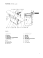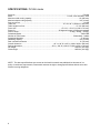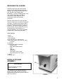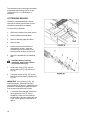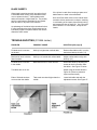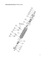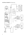
1
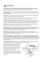
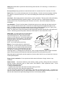
This Manual is Bookmarked
Operating Instructions and Parts Manual
16-inch Jointer
Model PJ1696
WMH TOOL GROUP
2420 Vantage Drive
Elgin, Illinois 60124
Ph.: 800-274-6848
www.wmhtoolgroup.com
Part No. M-0460269
Revision B1 6/06
Copyright © WMH Tool Group
WARRANTY AND SERVICE
WMH Tool Group, Inc., warrants every product it sells. If one of our tools needs service or repair, one of our Authorized Service
Center located throughout the United States can give you quick service. In most cases, any of these WMH Tool Group Authorized
Service Centers can authorize warranty repair, assist you in obtaining parts, or perform routine maintenance and major repair on your
POWERMATIC® tools. For the name of an Authorized Service Center in your area call 1-800-274-6848.
MORE INFORMATION
WMH Tool Group is consistently adding new products to the line. For complete, up-to-date product information, check with your local
WMH Tool Group distributor, or visit powermatic.com.
WARRANTY
POWERMATIC products carry a limited warranty which varies in duration based upon the product.
WHAT IS COVERED?
This warranty covers any defects in workmanship or materials subject to the exceptions stated below. Cutting tools, abrasives and
other consumables are excluded from warranty coverage.
WHO IS COVERED?
This warranty covers only the initial purchaser of the product.
WHAT IS THE PERIOD OF COVERAGE?
The general POWERMATIC warranty lasts for the time period specified in the product literature of each product.
WHAT IS NOT COVERED?
The Five Year Warranty does not cover products used for commercial, industrial or educational purposes. Products with a Five Year
Warranty that are used for commercial, industrial or education purposes revert to a One Year Warranty. This warranty does not cover
defects due directly or indirectly to misuse, abuse, negligence or accidents, normal wear-and-tear, improper repair or alterations, or
lack of maintenance.
HOW TO GET SERVICE
The product or part must be returned for examination, postage prepaid, to a location designated by us. For the name of the location
nearest you, please call 1-800-274-6848.
You must provide proof of initial purchase date and an explanation of the complaint must accompany the merchandise. If our
inspection discloses a defect, we will repair or replace the product, or refund the purchase price, at our option.
We will return the repaired product or replacement at our expense unless it is determined by us that there is no defect, or that the
defect resulted from causes not within the scope of our warranty in which case we will, at your direction, dispose of or return the
product. In the event you choose to have the product returned, you will be responsible for the handling and shipping costs of the
return.
HOW STATE LAW APPLIES
This warranty gives you specific legal rights; you may also have other rights which vary from state to state.
LIMITATIONS ON THIS WARRANTY
WMH TOOL GROUP LIMITS ALL IMPLIED WARRANTIES TO THE PERIOD OF THE LIMITED WARRANTY FOR EACH
PRODUCT. EXCEPT AS STATED HEREIN, ANY IMPLIED WARRANTIES OR MERCHANTABILITY AND FITNESS ARE
EXCLUDED. SOME STATES DO NOT ALLOW LIMITATIONS ON HOW LONG THE IMPLIED WARRANTY LASTS, SO THE
ABOVE LIMITATION MAY NOT APPLY TO YOU.
WMH TOOL GROUP SHALL IN NO EVENT BE LIABLE FOR DEATH, INJURIES TO PERSONS OR PROPERTY, OR FOR
INCIDENTAL, CONTINGENT, SPECIAL, OR CONSEQUENTIAL DAMAGES ARISING FROM THE USE OF OUR PRODUCTS.
SOME STATES DO NOT ALLOW THE EXCLUSION OR LIMITATION OF INCIDENTAL OR CONSEQUENTIAL DAMAGES, SO
THE ABOVE LIMITATION OR EXCLUSION MAY NOT APPLY TO YOU.
2
WMH Tool Group sells through distributors only. The specifications in WMH catalogs are given as general information and are not
binding. Members of WMH Tool Group reserve the right to effect at any time, without prior notice, those alterations to parts, fittings,
and accessory equipment which they may deem necessary for any reason whatsoever.
TABLE OF CONTENTS
Safety Rules............................................................................................................................................ 4-5
Safety Decal ............................................................................................................................................... 6
Features ..................................................................................................................................................... 7
Specifications ............................................................................................................................................. 8
Receiving the Jointer .................................................................................................................................. 9
Installation & Assembly............................................................................................................................... 9
Fence Installation.............................................................................................................................. 10
Dust Hood......................................................................................................................................... 10
Start/Stop Switch .............................................................................................................................. 11
Electrical Connection ........................................................................................................................ 11
Adjustments.............................................................................................................................................. 11
Drive Belt.......................................................................................................................................... 11
Replacing Knife Inserts ..................................................................................................................... 12
Setting Outfeed Table....................................................................................................................... 12
Table Raising Limit Blocks................................................................................................................ 14
Infeed Table Adjustment ................................................................................................................... 14
Fence Adjustments ........................................................................................................................... 14
Operating Instruction ................................................................................................................................ 15
Hand Placement ............................................................................................................................... 15
Edge Jointing.................................................................................................................................... 15
Surfacing .......................................................................................................................................... 15
Rabbeting ......................................................................................................................................... 15
Jointing Warped Surfaces................................................................................................................. 16
Jointing Short or Thin Work .............................................................................................................. 16
Direction of Grain.............................................................................................................................. 16
Beveling ........................................................................................................................................... 16
Taper Cuts........................................................................................................................................ 16
Maintenance............................................................................................................................................. 17
Lubrication........................................................................................................................................ 17
Cutterhead Repairs........................................................................................................................... 18
Blade Inserts..................................................................................................................................... 19
Trouble-shooting....................................................................................................................................... 19
Parts Lists & Exploded Views:
Cutterhead Assembly................................................................................................................... 20-21
Fence Assembly .......................................................................................................................... 22-23
Stand Assembly........................................................................................................................... 24-25
Bed Assembly.............................................................................................................................. 26-27
Cutterhead Guard Assembly ........................................................................................................ 28-29
Infeed Table Assembly ................................................................................................................ 30-31
Outfeed Table Assembly.............................................................................................................. 32-33
Motor Assembly ........................................................................................................................... 34-35
Electrical Schematic ................................................................................................................................. 36
Preventive Maintenance ........................................................................................................................... 37
Parts & Service......................................................................................................................................... 38
3
!
SAFETY RULES
As with all machines, there is a certain amount of hazard involved with the use of this jointer. Use the
machine with the respect and caution demanded where safety precautions are concerned. When normal
safety precautions are overlooked or ignored, personal injury to the operator can result.
Read the manual. Read, understand, and follow the safety instructions found in this manual. Know the
limitations and hazards in using the model PJ1696 Jointer. Decals are placed on each machine as reminders
of good safety practice.
Installation. If mounting machine to the floor, use high quality anchor bolts through the mounting holes on
the base. If using a mobile base, be sure to lock the wheels.
Location. Use extra care in the location of the jointer in the shop. Place the machine so that potential
kickback area is not in line with aisles, doorways, wash stations, or other work areas.
Electrical grounding. Make certain that the machine frame is electrically grounded and that a ground lead is
included in the incoming electrical service. If a cord and plug are used, make certain the grounding lug
connects to a suitable ground. Follow the grounding procedure indicated in the National Electric Code.
Eye safety. Always wear approved safety goggles, glasses, or a face shield when operating this machine.
(Note: common eyeglasses are only impact-resistant, they are not safety glasses.)
Personal protection. Before operating the machine, remove tie, rings, watch and other jewelry and roll up
sleeves above the elbows. Remove all loose clothing and confine long hair. Protective type footwear should
be used. Where the noise exceeds the level of exposure allowed in Section 1910.95 of the OSHA
Regulations, use hearing protective devices. Do not wear gloves.
Guards. Be sure machine guards are in place and in good working order. Use them at all times on
operations where they can be used. If a guard must be removed for any operation, make sure it is replaced
immediately following completion of that operation.
Work area. Keep the floor around the machine clean and free of scrap material, saw dust, oil and other
liquids to minimize the danger of tripping or slipping. Be sure the table is free of all scrap, foreign material
and tools before starting to cut. Make certain the work area is well lighted and that a proper exhaust system is
used to minimize dust. Powermatic recommends the use of anti-skid floor strips on the floor area where the
operator normally stands and that each machine's work area be marked off. Provide adequate work space
around the machine.
Disconnect machine before performing any service or maintenance. A machine under repair should be
RED TAGGED to show it should not be used until the maintenance is complete.
Housekeeping. Before turning on machine, remove
all extra equipment such as keys, wrenches, scrap,
stock, and cleaning rags away from the machine.
Power on. On machines equipped with a manual
starter make sure the starter is in "OFF" position
before connecting power to machine.
Three inch rule. When working a piece of wood on
the jointer, follow the 3 inch radius rule. The hands
must never be closer than 3 inches to the cutterhead.
See Figure 1.
4
Always use a hold-down or push block when surfacing stock less than 12" inches long, or 3 inches wide, or
3 inches thick.
Do not perform jointing operations on material shorter than 8", narrower than 3/4" or less than 1/4" thick.
Depth of cut. Do not make cuts deeper than 3/4" when rabbeting. On other cuts such as edging, surfacing,
etc., depth of cut should not be over 1/16" to avoid overloading the machine and to minimize chance of
kickback.
Avoid tip-in. Never apply pressure to stock directly over the cutterhead. This may result in the stock tipping
into the cutterhead along with the operator's fingers. Follow the 3 inch rule. Position hands away from
extreme ends of stock, and push through with a smooth, even motion. Never back workpiece toward the
infeed table.
Avoid Kickback. "Pull-out" and the danger of kicked back stock can occur when the work piece has knots,
holes, or foreign materials such as nails. It can also occur when the stock is fed against the grain on the
jointer. The grain must run in the same direction you are cutting. Before attempting to joint, or plane, each
work piece must be carefully examined for stock condition and grain orientation.
NOTE: At certain times it may be necessary to plane against the grain when working with a swirl grain wood
or burls. With this type work the operator must use a lesser depth of cut and a slow rate of feed.
Hand safety. It is good practice to move the hands in
an alternate motion from back to front as the work
continues through the cut. Never pass the hands
directly over the cutter knife. As one hand approaches
the knives remove it from the stock in an arc motion
and place it back on the stock in a position beyond
the cutter knife (Figure 2).
NOTE: At all times hold the stock firmly.
Misuse. Do not use this jointer for other than its
intended use. If used for other purposes, Powermatic
disclaims any real or implied warranty and holds itself
harmless for any injury or damage which may result
from that use. Do not equip or use this jointer with a
motor larger than 7-1/2 Horsepower at 5,200 R.P.M. Use of a larger horsepower motor or higher cutterhead
speed voids the warranty and Powermatic holds itself harmless for any injury which may result.
If you are not thoroughly familiar with the operation of jointers, obtain advice from your supervisor, instructor
or other qualified person.
Drugs, alcohol, medication. Do not operate tool while under the influence of drugs, alcohol, or any
medication.
Health hazards. Some dust created by power sanding, sawing, grinding, drilling and other construction
activities contains chemicals known to cause cancer, birth defects or other reproductive harm. Some
examples of these chemicals are:
* Lead from lead-based paint.
* Crystalline silica from bricks and cement and other masonry products.
* Arsenic and chromium from chemically-treated lumber.
Your risk from these exposures varies, depending on how often you do this type of work. To reduce your
exposure to these chemicals, work in a well-ventilated area, and work with approved safety equipment, such
as those dust masks that are specifically designed to filter out microscopic particles.
5
Familiarize yourself with the following safety notices used in this manual:
!
!
CAUTION: (This means that if precautions are not heeded, it may result in minor or moderate
injury, and/or possible machine damage)
!
WARNING: (This means that if precautions are not heeded, it could result in serious injury or
possibly even death).
SAFETY
Familiarize yourself with the location and content of this decal on your machine.
FIGURE 3
3408256
6
FEATURES: PJ1696 Jointer
FIGURE 4
1.
2.
3.
4.
5.
6.
7.
8.
9.
10.
11.
12.
13.
Outfeed table
Fence
Fence Handle
Lock Lever
Cast Housing
Control Handle - Forward/Backward
Rack Column
Cutterhead Guard Plate
Eccentric Shaft
Base
Eccentric Shaft
Rabbeting Ledge
Cutter Guard
14.
15.
16.
17.
18.
19.
20.
21.
22.
23.
24.
25.
Guard Bracket Block
Pushbutton Switch
Cabinet
Table Lock
Door Latch
Cabinet Door
Table Raising/Lowering Handle
Infeed Table
Eccentric Shaft
Fence Base
Junction Box
Drive Belt Cover
7
SPECIFICATIONS: PJ1696 Jointer
Stock No. .............................................................................................................................................. 1791283
Motor .................................................................................................................. 7-1/2HP, 3Ph, 230/460V, 60Hz
Maximum width cutting capacity.....................................................................................................16" (406 mm)
Maximum depth cutting capacity .................................................................................................... 3/4" (19 mm)
Cuts per minute........................................................................................................................................ 20,800
Table size ....................................................................................................16" W x 96" L (406mm x 2438 mm)
Table height from floor .............................................................................................................37-1/2" (800 mm)
Fence size ................................................................................................47-1/4" L x 5-1/4" H (1200 x 133 mm)
Fence tilt ............................................................................................ 45 degrees forward, 45 degrees backward
Positive stops............................................................................................................. 45 deg., 90 deg., 135 deg.
Cutterhead speed............................................................................................................................... 5200 RPM
Number of knife inserts ......................................................................................................56 standard, 2 rabbet
Cutterhead diameter ......................................................................................................................... 4" (98 mm)
Rabbeting capacity......................................................................................................................... 3/4" (19 mm)
Dust connection diameter................................................................................................................ 6" (152 mm)
Overall dimension .................................................................... 46" L x 96" W x 43" H (1168 x 2438 x 1092 mm)
Packing dimension ...............................................................39" L x 102" W x 29-1/2" H (991 x 2591 x 749 mm)
Net weight ............................................................................................................................ 1280 lbs. (582 kgs.)
Gross weight ........................................................................................................................ 1400 lbs. (636 kgs.)
NOTE: The above specifications were current at the time this manual was published, but because of our
policy of continuous improvement, Powermatic reserves the right to change specifications without notice and
without incurring obligations.
8
RECEIVING THE JOINTER
Carefully unpack the jointer and all loose
items from the wood crate and inspect for
damage. Any damage should be reported to
your distributor and shipping agent
immediately. Before proceeding further, read
your manual thoroughly to familiarize
yourself with proper assembly, set-up,
maintenance, safety and operating
procedures.
Exposed metal parts such as the table and
fence have been given a protective coating at
the factory. This should be removed with a
soft cloth moistened with a solvent (such as
kerosene). Do not use acetone, gasoline or
lacquer thinner for this purpose. Do not use
an abrasive pad. After cleaning, it is
recommended that you cover all unpainted
surfaces with a good quality paste wax.
Crate contents:
1 jointer
1 dust chute
1 fence assembly
4 hex wrenches (3, 5, 8 and 10mm)
3 open-end wrenches (10-12mm, 12-14mm,
17-19mm)
2 push pads
1 helical cutter head tool package:
2 rabbet knives
8 two-sided standard knives
7 gibs
7 gib nuts
7 gib screws
1 hex wrench 5mm (L type)
3 hex wrenches 5mm (T type)
1 manual
1 warranty card
INSTALLATION AND
ASSEMBLY
Tools required
10mm hex wrench (provided)
Phillips screwdriver
The supplied tools are shipped inside the
bottom of the stand, and can be removed
through the dust outlet (A-Figure 5) on the left
side of the machine.
9
Remove the bolts holding the jointer to the
skid, and lift the machine from the skid using
a hoist. The strap should be suitable to lift
1320 pounds of weight, and should be placed
under the base casting as shown in Figure 6.
DO NOT place strap under the tables.
The jointer should be mounted to a solid,
level foundation, preferably a concrete floor.
The machine area should be clean, dry, well
ventilated and well lighted, with sufficient
space around the machine for operation and
maintenance work.
This machine is equipped with noise-reducing
table lips. The work site should, however, be
one which minimizes reverberant sound from
walls, ceilings and other equipment.
FENCE INSTALLATION
Mount the fence (A-Fig. 7) to the holes on the
jointer table with the two socket head cap
screws (B-Fig. 7), using a 10mm hex wrench.
Tighten the screws (B-Fig. 7) securely.
DUST HOOD
Mount the dust hood (C-Fig. 8), to the left
side of the jointer using the seven 1/4-20 x
1/2 screws (D-Fig. 8) provided on the
machine. Before mounting the dust hood,
make sure the hole in the base is covered by
the dust chute cover (shown in Fig. 5).
It is recommended a dust collection system of
appropriate size (at least 800 CFM) be
connected to the dust outlet via a 6" diameter
hose.
10
START / STOP SWITCH
The arm (E-Fig. 9) on which the pushbutton
switch is located is shipped in the down
position. The screws (F-Fig. 9) should be
loosened with a 10mm hex wrench and the
arm pivoted to upright position. Re-tighten
screws.
ELECTRICAL CONNECTION
IMPORTANT: Make sure the electrical
characteristics are the same between the
motor nameplate and the power source, and
make sure the circuit on which the jointer will
be used is properly fused and that the wire
size is correct.
!
WARNING: Electrical connections
must be made by a qualified
electrician. The machine must be
properly grounded to help avoid
electric shock and possible death.
1. Connect wires both to junction box and
power source (see electrical schematic, page
34). The green wire (ground) must be
properly grounded.
2. After wiring is complete, turn motor on
momentarily to check for proper direction of
rotation (cutterhead should rotate toward
infeed table). If rotation is in the wrong
direction, disconnect machine and switch any
two of the hot leads. Reconnect power and
confirm proper rotation.
3. Run the machine without cutting for a
short time to check that all powered functions
are operating properly.
ADJUSTMENTS
Tools required
17mm & 19mm spanner
DRIVE BELT
Remove the three crown nuts and washers
(A-Fig. 10) on the belt cover with a 17mm
spanner, and remove the cover. Use a
19mm spanner to adjust the nuts in the motor
support (B-Fig. 11).
11
Raise or lower motor support to obtain proper
tension, then re-tighten nuts.
NOTE: Proper tension will be achieved when
there is a small amount of deflection in the
belt when using moderate finger pressure.
See Figure 12.
REPLACING KNIFE INSERTS
The cutterhead on the PJ1696 is a solid steel
helical insert design with 56 two-sided
standard knives, and two rabbet knives on the
outboard end of the cutterhead. Replacing
knives is a simple process, and they will seat
themselves properly without having to be set
with a knife gauge.
After a period of use, dull knives should be
flipped over, replaced or re-ground. To
change a knife:
1.
Loosen the gib screw (C-Fig. 13) and
remove the knife (D-Fig. 13) from the
slot.
2.
Flip the knife 180 degrees and re-insert
it, then tighten the gib screw (C-Fig. 13).
To ensure optimal cutting, all knives in
the cutterhead should be flipped at the
same time.
!
WARNING: Tighten gib screws
firmly. Loose gib screws can result
in knives being thrown out of the
cutterhead, causing severe
damage to the machine and
possible serious or fatal injury to
the operator or bystanders.
SETTING OUTFEED TABLE
For accurate work in most jointing operations,
the outfeed table must be exactly level with
the knives at their highest point of revolution.
1.
Raise the outfeed table to its highest
point, and place a straight edge across it.
2.
Turn the cutterhead until one row of
knives is at its highest point.
12
3.
Lower the outfeed table until the straight
edge contacts a knife. Rock the
cutterhead slightly to make sure the apex
of the knife is contacting the straight
edge. Lock the outfeed table at that
setting.
After the outfeed table has been set at the
correct height, it should not be changed
except for special operations or after
replacing knives.
Examples of incorrect settings:
If the outfeed table is too high, the finished
surface of the workpiece will be curved,
shown in Figure 14.
If the outfeed table is too low, the work will be
gouged at the end of the cut, shown in Figure
15.
As a final check of the outfeed table
adjustment, run a piece of wood slowly over
the knives for 6 to 8 inches; it should rest
firmly on both tables, as shown in Figure 16,
with no open space under the finished cut.
13
TABLE RAISING LIMIT BLOCKS
A limit block, shown in Figure 17, is mounted
to the rear of each table. It sets the
maximum height the tables can be raised,
and is pre-set at the factory. If adjustment is
ever needed, loosen the hex nut (E-Fig. 17)
and turn the screw (F-Fig. 17) as needed.
Retighten hex nut (E-Fig. 17).
INFEED TABLE ADJUSTMENT
Loosen lock lever (A-Fig. 18) and move table
adjustment arm (B-Fig. 18) to raise or lower
infeed table. Gauge (C-Fig. 18) shows the
distance of travel. Re-tighten lock lever (AFig. 18).
FENCE ADJUSTMENTS
The fence (A-Fig. 19) tilts backward and
forward 45 degrees. It contains a 90-degree
stop (B-Fig. 19) and a 45-degree stop (C-Fig.
19). The stops should be checked for
accuracy with a square or protractor against
the fence, and adjusted if necessary.
To tilt the fence forward, loosen the lock lever
(D-Fig. 19) and tilt the fence using the handle
(E-Fig. 19). Re-tighten lock lever (D-Fig. 19).
To tilt the fence backward, loosen the lock
screw (D-Fig. 19), pivot the stop block (F-Fig.
19) out of the way, and tilt the fence using the
handle (E-Fig. 19). Re-tighten lock screw (DFig. 19).
To move the fence forward or backward
across the table, loosen lock screw (G-Fig.
19), then turn knob (H-Fig. 19). When
desired position is reached, re-tighten lock
screw (G-Fig. 19) securely.
OPERATING INSTRUCTION
NOTE: If you are inexperienced at jointing,
use scrap pieces of lumber to check settings
and get the feel of operations before
attempting regular work.
!
14
WARNING: Always use guard and
keep hands away from cutterhead.
HAND PLACEMENT
At the start of the cut, the left hand holds the
work firmly against the infeed table and fence
while the right hand pushes the work toward
the knives. After the cut is under way, the
new surface rests firmly on the outfeed table.
The left hand should press down on this part,
at the same time maintaining flat contact with
the fence. The right hand presses the work
forward and before the right hand reaches the
cutterhead it should be moved to the work on
the outfeed table. FOLLOW THE 3 INCH
RULE. NEVER PASS HANDS DIRECTLY
OVER THE CUTTERHEAD.
EDGE JOINTING
This is the most common operation for the
jointer. Set guide fence square with the table.
Depth of cut should be the minimum required
to obtain a straight edge. Do not make cuts
deeper than 1/8" in a single pass. Hold the
best face of the piece firmly against the fence
throughout the feed. See Figure 20.
SURFACING
Jointing the face of stock, or surfacing, is
shown in Figure 21. Adjust the infeed table for
depth of cut. Cuts of approximately 1/16” at a
time are recommended, as this allows better
control over the material being surfaced.
More passes can then be made to reach the
desired depth.
!
WARNING: Always use a hold down
or push block when surfacing short
stock or stock less than 3 inches
thick.
RABBETING
!
WARNING: A rabbet cut requires
removal of the cutter guard. Use
extreme caution and keep hands
clear of cutterhead. Always replace
guard immediately after rabbeting
operation is completed.
A rabbet is a groove cut along the edge of a
board. See Figure 21A. The width and
thickness of the wood to be rabbeted depends
upon the width and length of the rabbet.
However, never rabbet a piece of wood less
than 12” long.
15
Use push blocks to rabbet cut whenever
possible. The rabbeting capacity is 3/4”.
1. Disconnect machine from power source.
2. Set fence for desired width of rabbet.
3. Check width of the rabbet by measuring
the distance from end of knife in the
cutterhead to the fence.
4. Reconnect power. Lower infeed table
1/32” at a time and make successive cuts
until the desired depth of rabbet has been
obtained. See Fig. 21A. NOTE: It is
easier and safer to take a series of
shallow cuts.
JOINTING WARPED SURFACES
If the wood to be jointed is dished or warped,
take light cuts until the surface is flat. Avoid
forcing such material down against the table;
excessive pressure will spring it while passing
the knives, and it will spring back and remain
curved after the cut is completed.
JOINTING SHORT OR THIN WORK
When jointing short or thin pieces, use a push
block to eliminate all danger to the hands.
Two push blocks are shipped with your
jointer. You can also make your own easily
from scrap material. Two types are shown in
Figure 22.
DIRECTION OF GRAIN
Avoid feeding work into the jointer against the
grain. This will result in chipped and
splintered edges. See Figure 23. Feed with
the grain to obtain a smooth surface, as
shown in Figure 24.
BEVELING
To cut a bevel, lock the fence at the required
angle and run the work across the knives
while keeping it firmly against the fence and
tables. Several passes may be necessary to
achieve the desired result.
16
TAPER CUTS
One of the most useful jointer operations is
cutting an edge to a taper. The method can
be used on a wide variety of work. Tapered
legs of furniture are a common example.
Instead of laying the piece on the infeed
table, lower the forward end of the work onto
the outfeed table.
Do this very carefully, as the piece will span
the knives, and they will take a "bite" from the
work with a tendency to kick back unless the
piece is firmly held. Now push the work
forward as in ordinary jointing.
The effect is to plane off all the stock in front
of the knives to increase depth, leaving a
tapered surface. The ridge left by the knives
when starting the taper may be removed by
taking a very light cut according to the regular
method for jointing, with the infeed table
raised to its usual position.
Practice is required in taper operations, and
the beginner is advised to make trial cuts on
waste material. Taper cuts over part of the
length and a number of other special
operations can easily be done as the operator
gains experience.
MAINTENANCE
!
WARNING: Disconnect machine
from power source before
performing maintenance.
Check all screws and fasteners occasionally
and keep them tightened securely.
The table and fence surfaces must be kept
clean and free of rust for best results. Some
users prefer a paste wax coating. Another
option is talcum powder applied with a
blackboard eraser rubbed in vigorously once
a week; this will fill casting pores and form a
moisture barrier. This method provides a
table top that is slick and allows rust rings to
be easily wiped from the surface. Important
also is the fact that talcum powder will not
stain wood or mar finishes as wax pickup
does.
LUBRICATION
Use a high grade light grease on the steel
adjusting screws for the raising and lowering
mechanisms of the infeed and outfeed work
tables.
17
The cutterhead runs in two single-row sealed
and shielded ball bearings, which are prelubricated for life - no maintenance is
necessary.
CUTTERHEAD REPAIRS
The entire cutterhead assembly may be
removed for bearing replacement or other
cutterhead maintenance procedures.
To remove the cutterhead:
1.
Disconnect machine from power source.
2.
Lower infeed and outfeed tables.
3.
Remove rabbeting ledge and fence.
4.
Remove belts.
5.
Loosen the two bolts that hold the
cutterhead to the bed – these are
accessed from the underside of the
bearing blocks as shown in Figure 25.
6.
Slide the cutterhead out the rabbeting
side.
!
CAUTION: Before removing
cutterhead, wrap it with cloths to
prevent personal injury.
7.
Loosen lock screw (A-Fig. 26) and
remove pulley (B-Fig. 26) and key (CFig. 26).
8.
Take down screws (D-Fig. 26) on both
sides and remove bearing cap plates (EFig. 26).
IMPORTANT: If the bearings (G-Fig. 26)
need replacement, Powermatic strongly
recommends this be done by qualified service
personnel. The bearings are press fitted and
must be removed with an arbor press.
9.
18
To re-install the cutterhead, reverse the
above procedure. NOTE: Before
reinstalling, make sure the machine's
curved seats of the base casting are free
of dirt, dust or grease, to help ensure a
tight fit.
BLADE INSERTS
When blade inserts become dull enough so that it
is noticeable when cutting, they should be turned
over or replaced entirely. A sharp blade works
easier and results in longer blade life. The penalty
paid for a dull blade is less blade life and greater
wear and tear on all parts of the machine.
An advantage of the helical style cutterhead is that
if knife inserts develop nicks, these inserts can be
individually flipped or replaced without the need to
disturb the other inserts.
If the jointer is used often, keeping a spare set of
blade inserts on hand is recommended.
Gum and Pitch which collect on the inserts cause
excessive friction as the work continues, resulting
in overheating of the inserts, less efficient cutting,
and consequent loss of blade life. Use "Gum and
Pitch Remover" or oven cleaner, to wipe off the
inserts.
TROUBLE-SHOOTING (PJ1696 Jointer)
PROBLEM
POSSIBLE CAUSE
SOLUTION [with page #]
Finished stock is concave
on the end.
Knife tip is higher than outfeed table.
Raise outfeed table until it is on the
same level with tip of knife. [11]
Back end of stock is thicker
than front side.
Knife tip not leveled with outfeed table.
Adjust outfeed table to align with
knife tip. [11]
Finished stock is concave
in the middle.
Both tables have too much end fall.
Raise table ends by adjusting the
screws at the four corners under
the tables. See Figure 27 below.
Two tables are not in line.
Ends of finished stock are
cut more than the middle.
Adjust using the screws shown in
Figure 28. (Remove protective
caps to access screw).
Table ends are raised higher than the
middle.
Lower both table ends with the
adjustment screws. See Figure 27.
PARTS LIST: Cutterhead Assembly (PJ1696 Jointer)
Index
No.
Part
No.
Description
Size
Qty.
........... PJ1696-001 ................ Cutterhead Assembly (Items 2 thru 12 & 17 thru 21) ............................. 1
1 ......... PJ1696-014 ................ Cutterhead................................................. .......................................... 1
2 ......... PJ1696-002 ................ Left Bearing Housing ................................. .......................................... 1
3 ......... BB-6204ZZ ................. Ball Bearing ............................................... .......................................... 2
4 ......... PJ1696-003 ................ Bearing Washer......................................... .......................................... 1
5 ......... TS-2361081................ Lock Washer ............................................. M8..................................... 1
6 ......... TS-1490031................ Hex Cap Screw.......................................... M8 x 20 ............................. 1
7 ......... PJ1696-004 ................ Left Bearing Cap Plate............................... .......................................... 1
8 ......... TS-1503051................ Socket Head Cap Screw ............................ M6 x 20 ............................. 6
9 ......... PJ1696-005 ................ Right Bearing Housing ............................... .......................................... 1
10 ....... BB-6206ZZ ................. Bearing...................................................... .......................................... 2
11 ....... PJ1696-006 ................ Right Bearing Cap Plate ............................ .......................................... 1
12 ....... PJ1696-007 ................ Key............................................................ 8 x 8 x 40L ........................ 1
13 ....... PJ1696-008 ................ Cutterhead Sheave.................................... .......................................... 1
14 ....... PJ1696-009 ................ Retainer Washer........................................ .......................................... 1
15 ....... TS-2361101................ Lock Washer ............................................. M10................................... 1
16 ....... TS-1491021................ Hex Cap Screw.......................................... M10 x 20 ........................... 1
17 ....... PJ1696-010 ................ Gib ............................................................ ........................................ 58
18 ....... PJ1696-011 ................ Carbide Insert Knife-Rabbet (Sold in pkg of 2) ...................................... 2
19 ....... 6400013 ..................... Carbide Insert Knife (Sold in pkg of 10) ..... ........................................ 56
20 ....... PJ1696-012 ................ Gib Nut ...................................................... ........................................ 58
21 ....... PJ1696-013 ................ Gib Screw.................................................. ........................................ 58
22 ....... PJ1696-015 ................ Gib Pin ...................................................... ...................................... 116
20
Cutterhead Assembly (PJ1696 Jointer)
21
PARTS LIST: Fence Assembly (PJ1696 Jointer)
Index
No.
Part
No.
Description
Size
Qty.
........... PJ1696-100 ................ Fence Assembly (Items 19 thru 41)
1 ......... PJ1696-101 ................ Fence Support ........................................... .......................................... 1
2 ......... PJ1696-102 ................ Bracket ...................................................... .......................................... 1
3 ......... PJ1696-103 ................ Gear Column ............................................. .......................................... 1
4 ......... PJ1696-104 ................ Cutterhead Guard ...................................... .......................................... 1
5 ......... PJ1696-105 ................ Block ......................................................... .......................................... 1
6 ......... TS-1501051................ Socket Head Cap Screw ............................ M4 x 16 ............................. 1
7 ......... TS-1503031................ Socket Head Cap Screw ............................ M6 x 12 ............................. 2
8 ......... TS-1550071................ Flat Washer............................................... M10................................... 3
9 ......... TS-2361101................ Lock Washer ............................................. M10................................... 4
10 ....... TS-1491031................ Hex Cap Screw.......................................... M10 x 25 ........................... 6
11 ....... TS-1505051................ Socket Head Cap Screw ............................ M10 x 35 ........................... 2
12 ....... PJ1696-106 ................ Pinion Gear ............................................... .......................................... 1
13 ....... PJ1696-107 ................ Handwheel................................................. .......................................... 1
14 ....... PJ1696-108 ................ Handle....................................................... .......................................... 1
15 ....... PJ1696-109 ................ Collar......................................................... .......................................... 1
16 ....... TS-1491121................ Hex Cap Screw.......................................... M10 x 70 ........................... 1
17 ....... TS-2361121................ Lock Washer ............................................. M12................................... 2
18 ....... TS-1506051................ Socket Head Cap Screw ............................ M12 x 40 ........................... 2
19 ....... PJ1696-110 ................ Fence Bracket ........................................... .......................................... 1
20 ....... PJ1696-111 ................ Fence Hinge .............................................. .......................................... 1
21 ....... PJ1696-112 ................ Fence Hinge Shaft ..................................... .......................................... 6
22 ....... TS-1523031................ Socket Set Screw ...................................... M6 x 10 ............................. 3
23 ....... TS-2311081................ Hex Nut (Full) ............................................ M8..................................... 4
24 ....... TS-1490051................ Hex Cap Screw.......................................... M8 x 30 ............................. 2
25 ....... PJ1696-113 ................ Left Tilt Bracket ......................................... .......................................... 1
26 ....... PJ1696-114 ................ Right Tilt Bracket ....................................... .......................................... 1
27 ....... PJ1696-115 ................ Support Shaft ............................................ .......................................... 1
28 ....... TS-2360121................ Flat Washer............................................... M12................................... 3
29 ....... PJ1696-116 ................ Locking Handle.......................................... .......................................... 1
30 ....... TS-2331121................ Cap Nut ..................................................... M12................................... 1
31 ....... PJ1696-117 ................ Pin............................................................. ∅5x20L ............................. 1
32 ....... PJ1696-118 ................ Fence Hinge Base ..................................... .......................................... 2
33 ....... TS-1540081................ Hex Nut (Full) ............................................ M12................................... 1
34 ....... PJ1696-119 ................ Fence Body ............................................... .......................................... 1
35 ....... PJ1696-120 ................ Handle Rod................................................ .......................................... 1
36 ....... PJ1696-121 ................ Handle....................................................... .......................................... 1
37 ....... PJ1696-122 ................ Stop Plate, -90 Degree .............................. .......................................... 1
38 ....... PJ1696-123 ................ Collar......................................................... .......................................... 1
39 ....... TS-2361081................ Lock Washer ............................................. M8..................................... 1
40 ....... TS-1490031................ Hex Cap Screw.......................................... M8 x 20 ............................. 1
41 ....... TS-1490061................ Hex Cap Screw.......................................... M8 x 35 ............................. 2
42 ....... TS-1505021................ Socket Head Cap Screw ............................ M10 x 20 ........................... 4
43 ....... TS-1523041................ Socket Set Screw ...................................... M6 x 12 ............................. 1
44 ....... TS-2311101................ Hex Nut (Full) ............................................ M10................................... 1
45 ....... TS-2361101................ Lock Washer ............................................. M10................................... 2
46 ....... TS-1550071................ Flat Washer............................................... M10................................... 2
22
Fence Assembly (PJ1696 Jointer)
23
PARTS LIST: Stand Assembly (PJ1696 Jointer)
Index
No.
Part
No.
Description
Size
Qty.
1 ......... PJ1696-201 ................ Stand......................................................... .......................................... 1
2 ......... TS-0680042................ Flat Washer............................................... 3/8................................... 10
3 ......... TS-0060031................ Hex Cap Screw.......................................... 3/8-16 x 3/4 ....................... 4
4 ......... TS-0720091................ Lock Washer ............................................. 3/8..................................... 4
5 ......... PJ1696-202 ................ Safety Plate............................................... .......................................... 1
6 ......... TS-1533032................ Pan Head Machine Screw.......................... M5 x 8 ............................... 3
7 ......... PJ1696-203 ................ Control Cord .............................................. .......................................... 1
8 ......... PJ1696-204 ................ Plate.......................................................... .......................................... 1
9 ......... PJ1696-205 ................ Contactor Box............................................ .......................................... 1
........... PJ1696-232 ................ Fuse (shown on page 36)........................... .......................................... 1
........... PJ1696-233 ................ Transformer (shown on page 36) ............... .......................................... 1
........... PJ1696-234 ................ Contactor (shown on page 36) ................... .......................................... 1
........... PJ1696-235 ................ Overload Relay (shown on page 36) .......... .......................................... 1
10 ....... PJ1696-206 ................ Cord Clamp ............................................... BG-19................................ 2
11 ....... PJ1696-207 ................ Junction Box.............................................. .......................................... 1
12 ....... TS-1550031................ Flat Washer............................................... M5..................................... 2
13 ....... TS-1533032................ Pan Head Machine Screw.......................... M5 x 10 ............................. 2
14 ....... PJ1696-208 ................ Terminal Strip............................................ 30A ................................... 1
15 ....... PJ1696-209 ................ Pan Head Machine Screw.......................... M5 x 25 ............................. 2
16 ....... PJ1696-210 ................ Switch Arm ................................................ .......................................... 1
17 ....... TS-2361061................ Lock Washer ............................................. M6..................................... 9
18 ....... TS-1503021................ Socket Head Cap Screw ............................ M6 x 10 ............................. 9
19 ....... PJ1696-211 ................ Switch ....................................................... .......................................... 1
21 ....... PJ1696-212 ............... Pan Head Machine Screw.......................... M5 x 16 ............................. 2
22 ....... PJ1696-213 ................ Dust Chute................................................. .......................................... 1
23 ....... PJ1696-214 ................ Right Side Door ......................................... .......................................... 1
24 ....... PJ1696-215 ................ Latch ......................................................... .......................................... 1
25 ....... PJ1696-216 ................ Motor Cover............................................... .......................................... 1
26 ....... PJ1696-217 ................ Stud........................................................... 3/8-16 x 4 .......................... 3
27 ....... TS-0570031................ Hex Nut ..................................................... 3/8-16................................ 6
28 ....... TS-059303.................. Cap Nut ..................................................... 3/8-16................................ 3
29 ....... PJ1696-218 ................ Switch Cord ............................................... .......................................... 1
30 ....... TS-0207021................ Socket Head Cap Screw ............................ 1/4-20 x 1/2 ....................... 7
31 ....... TS-0720071................ Lock Washer ............................................. 1/4..................................... 7
24
Stand Assembly (PJ1696 Jointer)
25
PARTS LIST: Bed Assembly (PJ1696 Jointer)
Index
No.
Part
No.
Description
Size
Qty.
1 ......... PJ1696-301 ................ Table Base ................................................ .......................................... 1
2 ......... TS-0090061................ Hex Cap Screw.......................................... 3/8-16 x 1-1/4 .................... 6
3 ......... PJ1696-302 ................ Pointer....................................................... .......................................... 1
4 ......... TS-2361061................ Lock Washer ............................................. M6..................................... 2
5 ......... TS-1534032................ Pan Head Machine Screw.......................... M6 x 10 ............................. 2
6 ......... TS-0720091................ Lock Washer ............................................. 3/8................................... 17
7 ......... TS-0060051................ Hex Cap Screw.......................................... 3/8-16 x 1 .......................... 8
8 ......... TS-0720111................ Lock Washer ............................................. 1/2................................... 10
9 ......... TS-0070011................ Hex Cap Screw.......................................... 1/2-13 x 1 .......................... 8
10 ....... PJ1696-303 ................ Table Lifting Handle................................... .......................................... 1
11 ....... PJ1696-304 ................ Bushing ..................................................... .......................................... 2
12 ....... PJ1696-305 ................ Pivot Shaft................................................. .......................................... 2
13 ....... PJ1696-319 ................ Cap Nut ..................................................... 1/2-13................................ 2
14 ....... PJ1696-306 ................ Hex Cap Screw.......................................... 1/2-13 x 2 3/4 .................... 2
15 ....... TS-0680061................ Flat Washer............................................... 1/2..................................... 2
16 ....... PJ1696-307 ................ Lock Handle............................................... .......................................... 2
17 ....... PJ1696-308 ................ Stroke Fixed Block..................................... .......................................... 2
18 ....... PJ1696-309 ................ Ring........................................................... .......................................... 2
19 ....... TS-0209071................ Socket Head Cap Screw ............................ 3/8-16 x 1-1/2 .................... 2
20 ....... PJ1696-310 ................ Flanged Hex Head Nut .............................. 3/8-16................................ 2
21 ....... PJ1696-311 ................ Protector Cover ......................................... .......................................... 2
22 ....... PJ1696-312 ................ Knob Handle.............................................. .......................................... 2
23 ....... PJ1696-313 ................ Table Lifting Handle................................... .......................................... 1
24 ....... PJ1696-314 ................ Table Up Adjustment Plate ........................ .......................................... 2
25 ....... TS-0209091................ Socket Head Cap Screw ............................ 3/8-16 x 2 .......................... 4
26 ....... TS-0561021................ Hex Nut ..................................................... 5/16-18.............................. 4
27 ....... TS-0051091................ Hex Cap Screw.......................................... 5/16-18 x 2 ........................ 2
28 ....... PJ1696-315 ................ Depth Label ............................................... .......................................... 1
29 ....... TS-0051151................ Hex Cap Screw.......................................... 5/16-18 x 3-1/2 .................. 1
30 ....... TS-0051111................ Hex Cap Screw.......................................... 5/16-18 x 2-1/2 .................. 1
31 ....... PJ1696-316 ................ Adjustment Plate ....................................... .......................................... 2
32 ....... TS-0561031................ Hex Nut ..................................................... 3/8-16................................ 8
33 ....... TS-0209031................ Socket Head Cap Screw ............................ 3/8-16 x 3/4 ....................... 3
34 ....... PJ1696-401 ................ Rabbeting Table ........................................ .......................................... 1
35 ....... PJ1696-318 ................ Bracket Block ............................................ .......................................... 1
36 ....... TS-0209111................ Socket Head Cap Screw ............................ 3/8-16 x 2-1/2 .................... 4
37 ....... TS-0267051................ Socket Set Screw ...................................... 1/4-20 x 1/2 ....................... 2
26
Bed Assembly (PJ1696 Jointer)
27
PARTS LIST: Cutterhead Guard Assembly (PJ1696 Jointer)
Index
No.
Part
No.
Description
Size
Qty.
1 ......... PJ1696-402 ................ Cutter Guard.............................................. .......................................... 1
2 ......... PJ1696-407 ................ Collar......................................................... .......................................... 1
3 ......... PJ1696-403 ................ Guard Post ................................................ .......................................... 1
4 ......... PJ1696-404 ................ Spring........................................................ .......................................... 1
5 ......... PJ1696-405 ................ Collar......................................................... .......................................... 1
6 ......... TS-1523051................ Socket Set Screw ...................................... M6 x 16 ............................. 2
7 ......... TS-1523031................ Socket Set Screw ...................................... M6 x 10 ............................. 1
8 ......... PJ1696-408 ................ Special Washer ......................................... .......................................... 1
9 ......... PJ1696-409 ................ Flat Head Machine Screw.......................... M8 x 16 ............................. 1
28
Cutterhead Guard Assembly (PJ1696 Jointer)
29
PARTS LIST: Infeed Table Assembly (PJ1696 Jointer)
Index
No.
Part
No.
Description
Size
Qty.
1 ......... PJ1696-501 ................ Infeed Table Lip......................................... .......................................... 1
2 ......... PJ1696-502 ................ Infeed Table .............................................. .......................................... 1
3 ......... TS-1505061................ Socket Head Cap Screw ............................ M10 x 40 ........................... 4
4 ......... PJ1696-503 ................ Dust Deflector............................................ .......................................... 1
5 ......... TS-2361051................ Lock Washer ............................................. M5..................................... 5
6 ......... TS-1502051................ Socket Head Cap Screw ............................ M5 x 20 ............................. 5
7 ......... TS-1540031................ Hex Nut ..................................................... M5..................................... 5
8 ......... PJ1696-504 ................ Table Lifting Support Base......................... .......................................... 1
9 ......... PJ1696-505 ................ Table Raising Link Bar............................... .......................................... 2
10 ....... PJ1696-506 ................ Bushing ..................................................... .......................................... 8
11 ....... PJ1696-507 ................ Pivot Shaft................................................. .......................................... 6
12 ....... PJ1696-508 ................ Adjustment Shaft ....................................... .......................................... 2
13 ....... TS-1525031................ Socket Set Screw ...................................... M10 x 16 ........................... 8
14 ....... PJ1696-509 ................ Special Bolt, for Spring .............................. 1/4-20 x 3 .......................... 2
15 ....... TS-0570011................ Hex Nut ..................................................... 1/4-20................................ 4
16 ....... PJ1696-510 ................ Table Lifting Spring.................................... .......................................... 2
30
Infeed Table Assembly (PJ1696 Jointer)
31
PARTS LIST: Outfeed Table Assembly (PJ1696 Jointer)
Index
No.
Part
No.
Description
Size
Qty.
1 ......... PJ1696-601 ................ Outfeed Table Lip ...................................... .......................................... 1
2 ......... PJ1696-602 ................ Outfeed Table............................................ .......................................... 1
3 ......... TS-1505061................ Socket Head Cap Screw ............................ M10 x 40 ........................... 4
4 ......... PJ1696-603 ................ Table Lifting Support Base......................... .......................................... 1
5 ......... PJ1696-604 ................ Table Raising Link Bar............................... .......................................... 2
6 ......... PJ1696-605 ................ Bushing ..................................................... .......................................... 8
7 ......... PJ1696-606 ................ Pivot Shaft................................................. .......................................... 6
8 ......... PJ1696-607 ................ Adjustment Shaft ....................................... .......................................... 2
9 ......... TS-1525031................ Socket Set Screw ...................................... M10 x 16 ........................... 8
10 ....... PJ1696-608 ................ Table Lifting Spring.................................... .......................................... 2
11 ....... PJ1696-609 ................ Hanger....................................................... .......................................... 2
12 ....... TS-0570011................ Hex Nut ..................................................... 1/4-20................................ 4
32
Outfeed Table Assembly (PJ1696 Jointer)
33
PARTS LIST: Motor Assembly (PJ1696 Jointer)
Index
No.
Part
No.
Description
Size
Qty.
1 ......... PJ1696-701 ................ Motor....................................7-1/2HP, 3Ph 230/460V, 60Hz ................. 1
2 ......... PJ1696-702 ................ Motor Sheave ............................................ .......................................... 1
3 ......... TS-1525011................ Socket Set Screw ...................................... M10 x 10 ........................... 2
4 ......... PJ1696-703 ................ Motor Bracket ............................................ .......................................... 1
5 ......... TS-1550071................ Flat Washer............................................... M10................................... 3
6 ......... TS-2361101................ Lock Washer ............................................. M10................................... 6
7 ......... TS-2210451................ Hex Cap Screw.......................................... M10 x 45 ........................... 3
8 ......... TS-2311101................ Hex Nut (Full) ............................................ M10................................... 3
9 ......... PJ1696-704 ................ Support...................................................... .......................................... 1
10 ....... PJ1696-705 ................ Rod............................................................ M12 x 150 ......................... 1
11 ....... TS-2360121................ Flat Washer............................................... M12................................... 2
12 ....... TS-2311121................ Hex Nut (Full) ............................................ M12................................... 5
13 ....... PJ1696-706 ................ Motor Cord ................................................ .......................................... 1
14 ....... PJ1696-707 ................ V-Belt ........................................................ .......................................... 2
34
Motor Assembly (PJ1696 Jointer)
35
ELECTRICAL SCHEMATIC (PJ1696 Jointer)
36
Preventive Maintenance
Checklist for Model PJ1696 Jointer
Monthly:
[
] Inspect entire machine for loose bolts, nuts, screws. Tighten and replace as necessary.
[
] Clean table and cutterhead area, removing sawdust and chips with a soft bristle brush. Remove gum and
pitch with oven cleaner.
[
] Lubricate adjusting screws beneath infeed and outfeed tables with a good grade non-hardening grease.
[
] Clean table surface. If rusted, use paste mixture of household ammonia, a good commercial detergent
and 000 steel wool. Wash table down with hot, soapy water, rinse and dry thoroughly. Coat surface with
talcum powder, rubbing briskly into surface with a clean blackboard eraser.
[
] Check belt condition. Replace as needed. Dress with parafin. Check belt tension.
[
] Check motor for loose wiring and sawdust congestion, pulleys tight and in line.
[
] Check bearings. Replace any bad or suspect bearings immediately.
[
] Check fence accuracy.
[
] Check and re-set fence stops at 45 and 90 degree positions.
[
] Check electrical controls function. Clean dust from internal parts of magnetic control boxes.
37
Replacement Parts
To order parts or reach our service department, call 1-800-274-6848 between 7:30 a.m. and 6:00 p.m. (CST),
Monday through Friday. Having the Model Number and Serial Number of your machine available when you
call will allow us to serve you quickly and accurately.
38
39
WMH Tool Group
2420 Vantage Drive
Elgin, Illinois 60124
Phone: 800-274-6848
www.wmhtoolgroup.com
40