1
FACILITATING THE
MODELLING OF EMBEDDED
GENERATION
CONTRACT NUMBER: K/EL/00321/00/00
URN NUMBER: 05/973
The DTI drives our ambition of
‘prosperity for all’ by working to
create the best environment for
business success in the UK.
We help people and companies
become more productive by
promoting enterprise, innovation
and creativity.
We champion UK business at home and
abroad. We invest heavily in
world-class science and technology.
We protect the rights of working
people and consumers. And we
stand up for fair and open markets
in the UK, Europe and the world.
FACILITATING THE MODELLING OF EMBEDDED
GENERATION
K/EL/00321/00/00
URN 05/
Contractor
IPSA Power Ltd
The work described in this report was carried
out under contract as part of the DTI New and
Renewable Energy Programme, which is
managed by Future Energy Solutions. The views
and judgements expresses in this report are
those of the contractor and do not necessarily
reflect those of the DTI or Future Energy
Solutions
First published 2005
Copyright IPSA Power Ltd
Executive Summary
Wind turbines require controllers for them to function effectively and efficiently. In
order to plan and operate the electricity networks satisfactorily it is necessary to
model the operation of these control systems. Some commercially available power
system analysis packages include user modelling capabilities, however a very high
level of programming and power system analysis ‘know how’ is often required to
make use of them. Such a level of development effort is clearly unacceptable for the
smaller plant sizes involved in embedded generation.
The project objective was to develop computer programs to:
•
Provide interactive graphic facilities to enable the construction of controller
block diagrams with the required range of transfer functions required for
embedded and renewable generation.
•
Construct ‘model engines’ that can be tested ‘stand alone’ and also called by
other analysis programs.
•
Integrate the model engines into an existing Grid code compliant power
system analysis tool and develop sample wind turbine controllers and
demonstrate their operation in the combined application.
The project comprised four phases:
Phase 1 developed a stand-alone block diagram modelling application to build
controller block diagrams graphically. This was used to construct and store
controller models for use in the engine.
Phase 2 produced the controller modelling simulation engine (CMEngine) with a
fully documented API.
Phase 3 combined the graphical tool with the modelling engine developed in the
first two phases to produce an integrated application, called UDM+. This was used
to create controllers, and to study and validate their characteristics in isolation from
the power system.
Phase 4 integrated the engine into the IPSA+ power system application. The
controller models were then used directly alongside the full power system model.
Sample control schemes for wind-turbines were modelled and their operation
verified during simulations of disturbances in the power system network.
The seamless integration of the CMEngine inside IPSA+, and the combination of
IPSA+ and the UDM+ program form a very powerful tool to develop and model
controllers for embedded generation. The stability simulation of the example
Page i
system and control models proves the viability of this approach and demonstrates
its ease of use.
The UDM+ application marks a major improvement in the ability to easily represent
and develop controller models for new and renewable generation. The fast
development time means a large number of different controller variations can be
developed and tested, not in isolation, but on real power system networks with new
and conventional generation represented.
The widespread use of IPSA+ throughout the UK DNO’s should ensure that these
new facilities will be used effectively. The CMEngine itself is a vendor neutral
modelling solution; it is in no way tied to IPSA+ but has the potential to be
embedded in other projects or products.
Page ii
Contributors to the report:
Dr John Heath
Mr Paul Bernat
Dr Graeme Bathurst
IPSA Power Ltd
IPSA Power Ltd
IPSA Power Ltd
Page iii
Table of Contents
Page
1
Introduction .......................................................................................... 1
2
Controller Modelling Program Architecture ...................................... 3
2.1
2.2
2.3
2.4
2.5
2.6
2.7
Coding .................................................................................................................. 3
The System .......................................................................................................... 4
System Items ....................................................................................................... 4
2.3.1Junctions ................................................................................................... 4
2.3.2Adders
................................................................................................... 4
2.3.3Multipliers ................................................................................................... 5
2.3.4Operators ................................................................................................... 5
2.3.5Saturation functions ................................................................................... 5
2.3.6Time Delays ................................................................................................ 5
2.3.7Limiters ................................................................................................... 5
2.3.8Logic
................................................................................................... 5
2.3.9User Defined ............................................................................................... 5
Diagram Model .................................................................................................... 6
The Graphics ........................................................................................................ 6
Orthogonality and Alignment ............................................................................. 6
Resizing ................................................................................................................ 6
3
The Application .................................................................................... 8
3.1
3.2
3.3
3.4
3.5
3.6
3.7
3.8
Toolbars and Stack Bar........................................................................................ 8
Menus................................................................................................................... 9
Tables ................................................................................................................... 9
Property Dialogs .................................................................................................10
Filing....................................................................................................................12
Printing ................................................................................................................14
A completed Example controller........................................................................14
Simulation ...........................................................................................................14
3.8.1Running the test simulation..................................................................... 15
4
Controller Modelling Engine Architecture ....................................... 17
4.1
4.2
The Structure of the API .....................................................................................17
4.1.1Message and Error Handling ................................................................... 18
4.1.2Types of API routines ............................................................................... 18
4.1.3External I/O connection ............................................................................ 18
4.1.4Packaging of the CMEngine..................................................................... 18
Main API functions..............................................................................................19
5
Integration into a Power System Application.................................. 21
5.1
5.2
5.3
5.4
5.5
5.6
5.7
IPSA+ ...................................................................................................................21
IPSA+ Transient Stability Calculation ................................................................21
Reading CMP model files ...................................................................................22
Association with IPSA+ plant objects ................................................................22
5.4.1Induction machines .................................................................................. 23
5.4.2Synchronous Machines............................................................................ 23
CMEngine embedding and model loading........................................................25
Signal connection and linking the Stability calculation to the CMEngine .......25
CMP model results reporting .............................................................................26
6
A real world example ........................................................................ 28
Page iv
6.1
6.2
6.3
Sample network ..................................................................................................28
DFIG controller models.......................................................................................29
Transient Stability Study ....................................................................................32
7
8
9
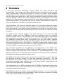
Further Development......................................................................... 35
Conclusions ........................................................................................ 36
References: ......................................................................................... 37
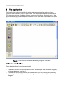
Page v
Facilitating the Modelling of Embedded Generation
1
Introduction
Renewable and embedded generation is becoming an increasing proportion of the
UK generation portfolio. When this type of generation was first added to the
electricity networks it was essentially uncontrolled; i.e. no attempt was made to vary
the generator output (either real or reactive power) in response to network
conditions such as voltage and frequency. Provided that uncontrolled generation
constitutes only a small proportion of the total this is a reasonable approach to take.
However, as more and more of the UK generation ceases to be provided by the
traditional large scale generation it is essential at least some of this new generation
is controllable. Indeed, amendments to the Grid Codes are planned to address this
situation.
In order to plan and operate the electricity networks satisfactorily it is necessary to
model the operation of these control systems. Some commercially available power
system analysis packages include user modelling capabilities, however a very high
level of programming and power system analysis ‘know how’ is often required to
make use of them. Such a level of development effort is clearly unacceptable for the
smaller plant sizes involved in embedded generation.
This project’s goal was to develop an easy-to-use controller modelling facility that is
capable of handling the various types of embedded generation now being found in
distribution networks. It must generate ‘enginised models’ that any suitable power
system analysis program will be able to ‘call’ from its dynamic simulation module.
As a key requirement the system shall be usable by a reasonably competent power
system engineer, and will not require either computer programming or control
systems expertise.
There are three major parts to the project:
1. The first part is a computer program to enable a controller transfer function to
be specified by ‘drawing’ its block diagram, and to provide off-line model
simulation capabilities.
2. The second part is the capability to generate ‘model engines’, i.e. computer
code that can be called by other analysis programs and which meets the
calculation requirements for dynamic simulation, e.g. data validation, input
and output variables, model initialisation, numerical integration, etc.
3. The last part is to integrate the model engines into an existing Power system
modeling application, and to validate its use with a real system and
controllers.
IPSA Power Ltd was commissioned to carry out this project under the New and
Renewable Energy Programme and supported by the Department of Trade and
Industry (DTI). This report provides full details of the project.
Page 1
Facilitating the Modelling of Embedded Generation
Page 2
Facilitating the Modelling of Embedded Generation
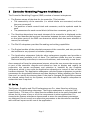
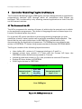
2
Controller Modelling Program Architecture
The Controller Modelling Program (CMP) consists of several subsystems:
•
The System stores all the data for the controller. This includes:
• The connectivity of the controller (i.e. which blocks are connected, and how
they are connected)
• The position of each control block and connector, and the symbols used for
each
• The parameters for each control block (all the time constants, gains, etc.)
•
The Graphics determines how each element of the controller is displayed on the
screen, and handles the low-level interaction between the user and the diagram,
so that other parts of the CMP can determine which block has been selected or
moved, for example.
•
The File I/O subsystem provides file reading and writing capabilities
•
The Engine handles all the calculation aspects of the controller, and also provides
the interface to any dynamic simulation packages.
•
The Application subsystem links the other subsystems together and provides a
graphical user interface to all of them. The interface allows the user to create,
draw and modify controllers, to save and load them, and eventually to test them.
As an example of how the subsystems interact, when the user moves the mouse on
to part of the controller diagram and selects an item to display and modify its
properties, the mouse movement and selection is handled by the Graphics
subsystem, which in turn calls the Application subsection to instruct it that an item
has been selected. The Application subsystem calls the System subsystem to get the
parameters for the selected element and then displays a dialog allowing the user to
view and / or modify the element data. If the data is changed the Application passes
the altered values back to the System, and also calls the Graphics subsystem to
redraw the item if required.
2.1 Coding
The System, Graphics and File I/O subsystems are C++ class libraries, which are
linked in by the Application subsystem. The Engine subsystem is a simple C-API
based library. The use of C++ class libraries enables them to be easily extended and
allows for the re-use of any or all of the components in other applications. For
example the System subsystem classes used to store the component parameters
are designed in such a way as to allow the parameters to be extended or modified
with minimal impact on the rest of the application.
Page 3
Facilitating the Modelling of Embedded Generation
2.2 The System
The System section of the Controller Modelling Program stores all the data for the
controller. The System architecture is divided into three parts:
•
The Network model stores the type and connectivity of each part of the
controller. The type is stored in the network model rather than the data model
since the type determines how many and what sort of connections are allowed to
a network element.
•
The Diagram model stores the location of the controller elements and the colours
and symbols used to draw each type of element.
•
The Data model stores the parameters for each controller element.
Each item in the controller will be a combination of one or more of these three
models.
2.3 System Items
Controller items are broadly categorised as either Blocks or Connectors. Connectors
have no types or parameters, other than recording the blocks that they join together.
There are several types of Blocks, each representing a different operation performed
on one or more input signals, and each therefore having a different set of
parameters:
2.3.1 Junctions
There are three types of Junction:
•
•
•
Standard: A normal junction, with one input connector and up to three output
connectors. No operation is performed on the input.
Input: A point where a signal is received into the controller. The signals that
can be received include direct, quadrature, real and imaginary voltages, field
and terminal currents, rotor angles and slips, electrical and mechanical
powers, and user-specified constant values.
Output: A point where a signal is sent from the controller. The signals that can
be sent include field voltage, rotor current and mechanical power.
2.3.2 Adders
Adders are points where up to three signals are combined by either addition or
subtraction to produce a single output.
Page 4
Facilitating the Modelling of Embedded Generation
2.3.3 Multipliers
Multipliers are points where up to three signals are combined by multiplication to
produce a single output.
2.3.4 Operators
Three types of Operator elements are provided:
• Lag
• Diff-lag
• Lead-lag
2.3.5 Saturation functions
Two types of saturation are available:
•
•
Standard IEEE model
Exponential model
2.3.6 Time Delays
A time delay element produces an output signal proportional to the input signal
after a specified time has elapsed.
2.3.7 Limiters
Limiters clip their input signal to produce an output signal. Depending upon the type
of limiter the output of previous controller elements may also be clipped.
2.3.8 Logic
There are three types of Logic switch. Each has one output and up to three inputs.
•
•
•
Simple: Either the largest, or the smallest, of the inputs are connected to the
output.
Time: Each input is connected to the output at a specified time.
External Control: The value of an external variable (usually the output of
another control element) is compared to upper and lower switch limit values.
Depending upon the type of External Control switch, and the results of the
comparison, the output will be connected to one of the three inputs.
2.3.9 User Defined
User defined elements allow the user to specify a combination of common
mathematical functions (trigonometric, hyperbolic, logarithmic, etc.) upon up to
three input signals to produce a single output signal.
Page 5
Facilitating the Modelling of Embedded Generation
2.4 Diagram Model
Each controller element stores its position on the diagram. This allows the controller
drawing to be saved and loaded, and also allows the CMP to determine suitable
points for attaching Connectors to block elements. The symbol for an Adder
element, for example, is drawn as a circle with four quadrants. Up to three of those
quadrants can have input signals, while the fourth quadrant has to have an output
signal. Each quadrant can therefore only have one Connector, while the Adder as a
whole must have one Connector “from” it (the output) and between one and three
Connectors to it (the inputs). Similar rules apply to the other elements.
2.5 The Graphics subsystem
The Graphics subsytstem determines how each element of the controller is
displayed and how the overall controller diagram is represented on the screen.
While the System section of the Controller Modelling Program (CMP) stores the
location and symbol type for each controller element it is the Graphics subsystem
that actually draws the items and handles the interaction with the user, usually via
the mouse.
The Graphics architecture consists of:
• a canvas upon which the various controller elements can be placed and moved.
• one or more views of the canvas.
A view determines how the canvas is displayed on the screen. Views can be
moved by panning or scrolling around the canvas. The resolution of the view
can be changed by zooming in or out. One canvas can potentially have several
views, each looking at a different part of the canvas at different resolutions,
although this capability is not used in the CMP as it is unlikely to be useful for
most controllers.
• canvas items, which are the representations of the controller elements such as
limiters and logic switches.
2.6 Orthogonality and Alignment
Controller diagrams have Connectors that are either horizontal or vertical, with rightangle turns. The CMP enforces right angle turns in Connectors even when the user
does not provide them. The CMP does not enforce horizontal or vertical lines, and
does not have a grid to which items are snapped. An alignment system is used
instead, where selected elements can be lined up either horizontally or vertically.
2.7 Resizing
The canvas itself can be resized in any direction to accommodate controllers that are
larger than initially anticipated. Resizing of the canvas is accomplished either by
specifying new dimensions, or simply by selecting and dragging a canvas item “off”
the canvas, which causes the CMP to automatically add extra room for drawing in
that direction.
Page 6
Facilitating the Modelling of Embedded Generation
Individual canvas items display their parameter values on-screen where appropriate,
and resize themselves to display those parameters as the parameters are changed.
Values are not clipped to fit a “fixed size” drawing element, instead the drawing
element grows to allow the value to be fully displayed. However, a minimum size is
enforced on canvas items to maintain good visual presentation of the diagram.
Page 7
Facilitating the Modelling of Embedded Generation
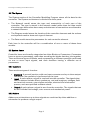
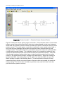
3
The Application
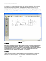
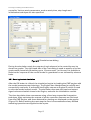
The Application subsystem links the other subsystems together and provides a
graphical user interface (GUI) to all of them. The interface consists of the standard
GUI elements such as windows, dialogs, menus and toolbars. The main part of the
application display is a window that contains a view from the Graphics section upon
the canvas used for the controller.
Figure 1: Overview of Controller Modelling Program interface
3.1 Toolbars and Stack Bar.
Three basic toolbars have been provided:
•
•
•
a standard toolbar for basic operations such as starting a new controller diagram,
printing a diagram, and so on.
a toolbar for controlling the view of the diagram, such as panning and zooming.
a drawing and selection toolbar for placing controller elements upon the
diagram.
Page 8
Facilitating the Modelling of Embedded Generation
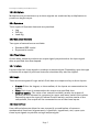
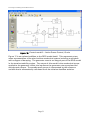
A variation on a toolbar, known as a stack bar, has been developed. This provides
quick access to common functions, such as displaying data in tabular form or
viewing reports. The stack bar is anchored to the side of the diagram unlike the
toolbars, which can be dragged to new positions on the screen. All the toolbars and
the stack bar can be individually hidden from view, increasing the available room for
the view on the diagram.
Figure 2: CMP items
3.2 Menus
Basic menu functions have been added, most of whose operations mimic elements
of the toolbars and the stack bar. Essentially they function as an alternate way to
perform the same operations, although in some cases there may be menu elements
not available on any tool or stack bar. Those menu items will be options less
commonly used and therefore not requiring GUI shortcuts.
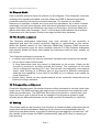
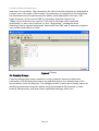
3.3 Tables
Tables have been created to display and modify the parameters for all controller
elements of a particular type e.g. the parameters for all the Time Delay type
Page 9
Facilitating the Modelling of Embedded Generation
elements in a controller. The parameters for each controller element are displayed in
a single row of the table. If the number of parameters is judged to be too large then
the parameters may be split across two tables, each displayed on its own “tab”
page. However, in the current CMP no controller elements require this.
Tables can be sorted by any column. Cells within the table can be selected
individually, or as a row or column, or as a “drag-select” rectangular area.
Selections can be copied and pasted, both within the CMP and to external programs
such as Microsoft Word or Excel.
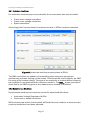
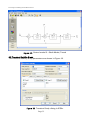
3.4 Property Dialogs
Figure 3: Tables
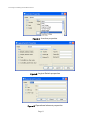
Property dialogs have been created for every controller element to allow the
parameters of individual elements to be modified simply by a double click of the
mouse button from the diagram. The dialogs provide a more user-friendly means of
modifying parameters than the tables, using the standard GUI features of radio
buttons, check boxes, pull-down lists of potential settings, and so on.
Page 10
Facilitating the Modelling of Embedded Generation
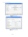
Figure 4: Junction properties
Figure 5: Logical Switch properties
Figure 6: Operational element properties
Page 11
Facilitating the Modelling of Embedded Generation
3.5 Filing
The diagram and parameters for a controller can be saved to disk and read back
from it. For new controllers the user is prompted for a file name. If a file exists with
the same name then the previous file is renamed to a back up and the new data
written to the selected name.
The file format is self-defining and plain text. The self-defining characteristic means
that the first part of the file contains definitions of the structure of the records in the
rest of the file, while the second part of the file contains the actual information on
the controller in the specified format. By writing the file as plain text rather than
binary the data can easily be viewed and modified by another application, although
modifications must abide by the format definitions given in the file to be successful.
There is some overhead in both file size and read / write time in using a plain text
format, however given that most files are expected to be relatively small the
advantages clearly outweigh the disadvantages.
Page 12
Facilitating the Modelling of Embedded Generation
##!IIF-IpsaPower-1.1
#
Header {
Version: "1.0+"
Program: "IPSA+ "
Type: "UDMmodel"
Title: "IPSA Generic Vqr - P"
Date: "14 Feb 2005 15:10:38"
Created: "jbh@fenris"
Format: "IPSAplus"
}
DefRec System {
Author: s ""
Comment: s ""
Version: i 1
ModelType: s "IndMachQAVR"
}
DefRec Diagram {
Width: d 2970, Height: d 2100
}
DefRec Analysis {
ConvergenceAccuracy: d 0.0001, DifferentialStep: d 0.0001
MaxIterations: i 40, SolutionType: i 1
}
Define UDMmodel Junction {
ID: i, Name: s, Type: s, SignalType: s, DblSignalValue: d, IntSignalValue: i,
Position: 2d
}
Define UDMmodel Sum {
ID: i, Name: s, TopConnect: i, RightConnect: i, BottomConnect: i, LeftConnect: i,
Position: 2d
}
Define UDMmodel Operational {
ID: i, Name: s, Type: s, Ka: d, Kb: d, Ta: d, Tb: d, Init: d, Position: 2d
}
Define UDMmodel Limiter {
ID: i, Name: s, Type: s, UpperLimit: d, LowerLimit: d, RiseRate: d, FallRate: d,
DeadbandRise: d, DeadbandFall: d, Position: 2d
}
Define UDMmodel Label {
ID: i, Owner: i, Position: 2d
}
Define UDMmodel Connector {
ID: i, Name: s, FromBlock: i, ToBlock: i, FromPt: 2d, ToPt: 2d, FromCount: i,
ToCount: i
}
Record UDMmodel Junction {
1 "Block1" "input" "Frequency" 0 0 44 227.625
15 "Block8" "output" "OpRotorQuadratureVoltage" 0 0 691 227.625
19 "Block10" "input" "TerminalVoltage" 0 0 226 272
}
Record UDMmodel Sum {
5 "Block3" 3 1 1 2 249 226.625
11 "Block6" 3 1 1 2 520 226.625
}
Record UDMmodel Multiplier {
7 "Block4" 325 227.625
}
Record UDMmodel Operational {
13 "Block7" "LeadLag" 5 0 0.05 1 1e-05 601 227.625
25 "Block13" "LeadLag" 100 -2 0 0 0 448 91
}
Figure 7: File format
Page 13
Facilitating the Modelling of Embedded Generation
3.6 Printing
A simple printing mechanism has been implemented whereby the diagram can be
sent to the operating system’s printing system.
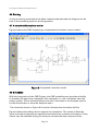
3.7 A completed Example controller
Figure 8 shows the CMP displaying a completed wind turbine control model.
Figure 8: Completed controller model
3.8 Simulation
With the integration of the CMP Engine, the CMP modelling tool provides a facility
to simulate the open-loop response of the controller; i.e. run in isolation from the
power system. This is accessed either from the Test button in the Analysis section
on the shortcut bar or from the Analysis menu.
The controller shown in Figure 8 is used to illustrate the simulation facility.
Figure 9 shows the dialog used to control the simulation. The values of both the
input and output elements are specified (excluded from constant and inputs). These
values may be switched during the study to simulate the step-response of the
Page 14
Facilitating the Modelling of Embedded Generation
controller. Various study parameters, such as study time, step length and
initialisation technique are also specified.
Figure 9: Simulation test dialog
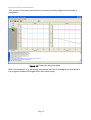
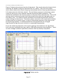
During the simulation study the outputs of each element in the controller may be
shown on graphs. The right hand side of the Test dialog is used to specify up to four
graphs each potentially containing up to 15 traces each. In this way it is possible to
examine the response of the control model in great detail on an element-by-element
basis.
3.8.1 Running the test simulation
After the OK button is clicked, the simulation begins by loading the CMP engine with
the model parameters and topology. The Engine then checks these for validity and
connectivity continuity. If successful the Engine returns an Engine ID, which is used
to refer the loaded control model. The simulation then sets the input and output
signal values and switch times in the Engine, and calls the initialisation routine.
The time simulation then commences using a fixed step trapezoidal integration
technique. After each step the outputs of all the controller elements are retrieved
from the CMP Engine, and those selected for plotting are displayed on the graphs
(Figure 10). Before starting the next step the time is incremented and any defined
switching operations are applied to the inputs.
Page 15
Facilitating the Modelling of Embedded Generation
This process is repeated until the time reaches the study length and the study is
completed.
Figure 10: Controller response plots
Both informational (e.g. switching operations) and error messages are displayed in
the progress window throughout the simulation study.
Page 16
Facilitating the Modelling of Embedded Generation
4
Controller Modelling Engine Architecture
The Controller Modelling Engine (CMEngine) has been designed with an applicationprogramming interface (API) through which all interactions with Engine are
managed. This is enforced by only allowing external applications to link to the API
not the internal routines.
4.1 The Structure of the API
The API is composed of a number of layers, of which only the external one is visible
to the application programmer. The choice of language for each of these layers is a
function of what purpose they serve.
For a general API, which interfaces to most programming languages on most
platforms, a basic C style function call is generally considered most effective. This
should be the only user-visible layer in the CMEngine, and should be fully
documented for the Application programmer. The CMEngine core software was
written in FORTRAN -77 dialect using constructs that all predate FORTRAN 90/95.
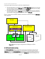
The Engine consists of the following layered structure:
•
•
.
User visible API – written in C, language bindings in C and C++
Internal private layer written in C that calls the Fortran API layer, the
FORTRAN routine definitions expressed in C format
• Internal private layer written in C++ that provides the external I/O section
• Engine API layer written in FORTRAN
• Core Engine written in FORTRAN
User Visible API - C
Internal private
layer - C
Error and
Message
Handling
Internal private I/O
layer – C++
Engine API layer – FORTRAN
Core CMEngine
Figure 11: CMEngine structure
Page 17
Facilitating the Modelling of Embedded Generation
4.1.1 Message and Error Handling
The internal private API layer provides a message and error reporting function,
allowing the CMEngine to report and store messages and errors. These can then be
queried through the main user visible API.
4.1.2 Types of API routines
The User Visible API function calls may be broadly split into the following groups:
•
•
•
•
•
•
•
•
•
Initialisation routines – set up the engine ready for use
Data set routines – set up the models
Input/Output element set routines – connect the external (i.e. from the Power
system simulation program) inputs and outputs to the internal modeling
values
Model Initialisation routines – initialize the models
Control routines – setting the analysis parameters used during the study
Run routines – run the actual calculations
Element get routines – get the elements output values as set by the
calculation
Reporting routines – get the messages, warnings and error messages
encountered during a study
Reset routines – reset the Engine to be re-used.
4.1.3 External I/O connection
One of most critical parts of the CMEngine API is how the engine is connected to the
external simulation tool. The I/O subsystem provides the interface between the Core
Engine internal values and the signals to and from the calling application. The
subsystem has been written in C++ to provide a dynamic object structure that to
implement this linkage. This structure is automatically generated as the input and
output elements values are specified.
4.1.4 Packaging of the CMEngine
The CM modeling routines with the API layer (the CMEngine) are packaged together
as an object library. This has been developed on both Windows and Unix platforms,
and is how the Engine will be linked in to the CM modeling application and other
analysis software. The language bindings for both C and C++ are defined in the
Engine API definition header file. This enables the main modeling application
programs to compile in the calls to the CMEngine.
Page 18
Facilitating the Modelling of Embedded Generation
4.2 Main API functions
Initialisation and Analysis settings:
IcmInit()
IcmReset()
IcmDeleteAll()
IcmUnloadModel()
Engine loading:
IcmStartDefinition()
IcmAddInput()
IcmAddConstInput()
IcmAddOutput()
IcmAddJunction()
IcmAddSum()
IcmAddMultiplier()
IcmAddOperational()
IcmAddLimiter()
IcmAddLogical()
IcmAddSaturation()
IcmAddTimeDelay()
IcmAddUserDefined()
IcmAddConnection()
IcmAddSignedConnection()
IcmAddNumConnection()
IcmEndDefinition()
IcmLoadModel()
IcmSetInputValue()
IcmSetOutputValue()
IcmSetElementValue()
Running calculations:
IcmInitialize()
IcmGetElementInitialized()
IcmSetStepLength()
IcmSetSystemTime()
IcmCalcIntegrationConsts()
IcmCalcIntegrationSoln()
Page 19
Facilitating the Modelling of Embedded Generation
Messages:
IcmGetNumMsgs()
IcmGetNumWarnings()
IcmGetNumErrors()
IcmGetMsgTxt()
IcmClearMessages()
Results retrieval:
IcmGetInputValue()
IcmGetOutputValue()
IcmGetElementValue()
State storage and retrieval:
IcmSaveIntegrationSoln()
IcmRestoreIntegrationSoln()
Page 20
Facilitating the Modelling of Embedded Generation
5
Integration into a Power System Application
Although the CMP can be used in its own right as a modelling application to
investigate the open loop response of a controller, its use as a tool to build
controller models for embedding in power system modelling applications is far
more important.
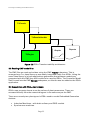
A Power System Application (PSA) must contain the following modelling and
analysis features to effectively host the CMEngine models:
•
•
Dynamic stability calculation
Machine and wind turbine models
There are a number of steps required to use CMP designed controllers inside a PSA:
•
•
•
•
•
•
•
Develop a means of reading CMP model files into the PSA.
Attach the control model to the controlled object in the power system model.
Embed the CMEngine inside the PSA.
Load the CMP models into the CMEngine.
Connect the PSA input and output signals to the CMEngine signals.
Connect the Stability calculation to the CMEngine solution routines.
Add reporting of CMP model results to the Stability results
5.1 IPSA+
IPSA+ has been used as the PSA platform for CMP integration. IPSA+ is in
widespread use in the UK DNO’s and provides all the facilities needed to support the
CMP and CMEngine.
The application architecture of IPSA+ is similar in concept to that of the CMP, and is
also written in C++ using class libraries with C-API based FORTRAN analysis
engines.
5.2 IPSA+ Transient Stability Calculation
IPSA+ uses an enginised library TSEngine to calculate the stability response of the
system. The IPSA+ classes TsFacade and TsResultsHandler. These classes control
the main operation and running of the calculation and the stability calculation
results and reporting functions, respectively.
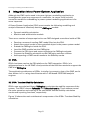
Figure 12 shows the main architectural components of the IPSA+ Transient Stability
calculation:
Page 21
Facilitating the Modelling of Embedded Generation
TsFacade
TsResultsHandler
Reports
Graphs
TSEngine
Figure 12: IPSA+ Transient stability architecture
5.3 Reading CMP model files
The CMP files are read and written using the CMP File I/O subsystem. This is
arranged as a C++ class library so was easily integrated easily into IPSA+. Using the
same class library is in both applications guarantees that whatever models are
generated with the CMP they will be able to be used by IPSA+. The Controller Model
itself is read into the CMP System subsystem, so this too was be added to the IPSA+
application.
5.4 Association with IPSA+ plant objects
IPSA+ uses property sheets to set the values of plant parameters. These are
accessed directly from the network diagram in the same way as the CMP.
There are currently two plant types in IPSA+ used to model Embedded Generation
devices:
•
•
Induction Machines – with both ordinary and DFIG models
Synchronous machines
Page 22
Facilitating the Modelling of Embedded Generation
5.4.1 Induction machines
For Induction machines there are potentially three controllers that may be added:
•
•
•
D-axis rotor voltage controllers
Q-axis rotor voltage controllers
Speed controllers
Accordingly the Property sheet for Induction motors in IPSA+ has been extended:
Figure 11: Induction machine property sheet in IPSA+
The CMP controllers are added by first enabling them using the appropriate
checkboxes, and then clicking on the button. This allows the user to specify the CMP
file using a file browser dialog. The type of the controller is checked before allowing
the controller to be attached to the induction machine. The Edit… button provides a
direct link to the CMP program so the model may be viewed or modified.
5.4.2 Synchronous Machines
Synchronous machines can have two controller associated with them:
•
•
Automatic Voltage Regulators (AVR’s)
Governors or speed controllers
IPSA+ already has built-in (hard coded) AVR and Governor models, so there are two
property sheets that have been adjusted.
Page 23
Facilitating the Modelling of Embedded Generation
Figure 11: AVR properties
Figure 12: Governor properties
Page 24
Facilitating the Modelling of Embedded Generation
5.5 CMEngine embedding and model loading
The CMEngine library provides a C-API. A new class UdmFacade has been added to
IPSA+ to provide an interface to the engine, both for the actual calculations and to
load it with the CMP model. This class oversees all I/O between IPSA+ and the
CMEngine.
5.6 Signal connection and linking the Stability calculation to the CMEngine
The CMP models have inputs and output signals that must be connected to the
appropriate system variables in IPSA+, i.e. to signals in the TSEngine. This needs to
be done both at CM model initialisation time and during each step in the time
simulation. In addition the CMEngine simulation routines also have to be run during
each step of the Stability calculation to calculate the response of the controller.
In fact because of the solution order used by the TSEngine, the values of the CMP
control signals are required at different phases of the time step simulation. For this
reason the TSEngine routines need to initiate actions in the CMEngine, i.e. call the
CMEngine routines directly. The following calculation steps need to be linked:
•
•
•
•
•
Controller initialisation
Trapezoidal constant calculation
Trapezoidal step solution calculation
Solution store
Solution restore
The solution store/restore functions save or restore the element output values on
demand. This is required because the TSEngine uses a variable step length, and
void tsudm_init()
void tsudm_const()
void tsudm_trap()
void tsudm_store()
void tsudm_restore()
int IUdmInitialize()
int IUdmCalcIntegrationConsts()
Æ
int IudmCalcIntegrationSoln()
Æ
int IudmSaveIntegrationSoln()
Æ
int IudmRestoreIntegrationSoln()
Æ
Æ
may restart a time step thus requiring the original values be restored.
In programming terms this means the connection of the following routines:
The routines on the left are in the TSEngine, the ones on the right in the CMEngine.
For reasons of flexibility, rather than hard code in this linkage, the TSEngine has
been modified to provide a decoupling layer in its API. Essentially this allows
external routines to be registered with the TSEngine as callbacks when the above
functions are called. If no routine is registered then no callback takes place. This
means there are no compile time dependencies between the CMEngine and the
TSEngine, only run time linkage takes place.
Page 25
Facilitating the Modelling of Embedded Generation
Linking the signals themselves is relatively straightforward:
•
•
During initialisation all controller model input and output signals are retrieved
from the system values in TSEngine. After the CMEngine initialises the model,
the output signals are then fed back into the TSEngine.
During the step solution, all controller model input signals only are retrieved
from the system values in TSEngine. The step solution is performed and then
the controller output signals are fed back into the TSEngine
Figure 13 shows the new IPSA+ Stability calculation architecture with the CMEngine
fully integrated.
TsFacade
TsResultsHandler
UdmFacade
Callback layer
I/O
Signal
I/O
Signal
I/O
TSEngine
Reports
CMEngine
Graphs
Figure 13: Stability Engine integrated with CMEngine in IPSA+
5.7 CMP model results reporting
The TsResultsHandler class controls the monitoring of individual network items
during the study, and is responsible for retrieving the required results from the
TSEngine. Since the TsResultsHandler forms the core of all the stability calculation
results handling, it was sensible to include the CMEngine results handling here as
Page 26
Facilitating the Modelling of Embedded Generation
well. To that end TsResultsHandler calls CMEngine to get results for monitored
items as required. This means that all the CM model results are seamlessly
integrated into the stability calculation. So that, for example, CM model element
outputs can be viewed as plots side-by-side with the power system network
variables.
Page 27
Facilitating the Modelling of Embedded Generation
6
A real world example
The main goal of this project is to produce an easy to use tool to model embedded
generation controllers in Power System Network stability simulation studies. A real
example makes it clear just how simple it is to use.
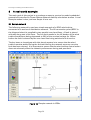
6.1 Sample network
The following network is used as a simple example of a DFIG wind turbine
connected to a section of distribution network. The HV connection point (BPCC in
the diagram below) is supplied by two parallel over-head lines. A fault is placed
mid-way along one of the lines. The line fault results in the HV busbar of the wind
turbine transformer being depressed to 30% of the nominal voltage for 150ms
before the fault is cleared by the over-head line being switched out of service.
The key issue to investigate with this simple system is to ensure that the wind
turbine remains stable during the fault and during the network recovery once the
fault has been cleared. It is important to ensure that the wind turbine control action
does not adversely affect the network performance during and post-fault.
Figure 14: Sample network in IPSA+
Page 28
Facilitating the Modelling of Embedded Generation
6.2 DFIG controller models
For stability studies it is only necessary to represent the important characteristics of
the DFIG. The following controller examples only represent the primary
characteristics for basic stability analysis. For full system studies, additional control
functionality will be represented.
The DFIG model in the IPSA+ transient engine requires two controllers for the
injected rotor voltage. The injected rotor voltages from the controller can be
specified in either a stator voltage orientated DQ reference frame, or on the system
reference frame. The controllers shown in Figure 15 and Figure 16 are specified on
the stator voltage DQ reference frame. In simple terms this means that the D-axis is
used to control the stator reactive power and the Q-axis is used to control the stator
active power, or rotor speed/slip.
Figure 15 shows a simple reactive power controller using the D-axis rotor voltage.
The stator reactive power is measured with input 1, this goes through a per-unit
power base transform from the external system base of 100MVA to the local
controller base of 2MVA. The negative sign is to compensate for the current
convention used in the transient stability program. The controller is specified on the
machine base as this greatly simplifies the representation of large wind farms using
the single coherent machine approach. Using this approach it is only necessary to
adjust a parameter in the scaling block as opposed to modifying all of the controller
parameters. Once the reactive power input has been scaled, it is subtracted from
the controller reference to create a reactive power error signal. This error signal
feeds into a Proportional-Integral (PI) controller which represents the combination of
the rotor converter control and the rotor converter itself. The converters used for
DFIG’s are typically high frequency PWM converters and can be adequately
represented in this fashion. The reactive power set point reference is determined
automatically by a backward solution of the controller from the inputs and outputs
defined by the load flow solution of the transient stability network.
Page 29
Facilitating the Modelling of Embedded Generation
Figure 15: Control model 1 – Reactive Power Control, D-axis
Figure 16 shows a simple active power controller. This controller has an inner stator
power control loop controlling the Q-axis rotor voltage based on the error between
measured active stator power and the derived active power reference from the outer
power control. The outer power controller constitutes a rotor speed control and a
fault ride through strategy that reduces the active power reference during low
voltage events. The speed control is a quadratic curve that maps the rotor speed to
a target active power output. The reference input (14) is present to adjust for any
numerical slack between this input and the transient load flow solution. The fault
ride through strategy implemented uses a logical switch to scale back the active
power in the event that the stator voltage drops below 90%. When the voltage is
greater than 90%, the scaling factor is 1.0, when it is less than 90%, the per-unit
stator voltage is used as the scaling factor. The active power reference is then
passed through a limiter to ensure power reference does not exceed the machine
output rating. The limiter also includes a positive ramp-rate limit that limits the
post-fault active power recovery.
Page 30
Facilitating the Modelling of Embedded Generation
Figure 16: Control model 2 – Active Power Control, Q-axis
Figure 17 is an optional addition to the DFIG model detail. This represents a two
mass representation of the wind turbine mechanical system including a soft shaft
with a degree of damping. The generator mass is an integral part of the DFIG model
in the transient stability engine. The output of this model is the mechanical torque
applied to the generator inertia, the inputs are the generator rotor speed and the
aerodynamic torque. The aerodynamic torque is represented by the reference
variable that is automatically calculated from the transient loadflow solution.
Page 31
Facilitating the Modelling of Embedded Generation
Figure 17: Control model 3 – Shaft Model, Tmech
6.3 Transient Stability Study
The transient stability study parameters are shown in Figure 18.
Figure 18: Transient Study dialog in IPSA+
Page 32
Facilitating the Modelling of Embedded Generation
Figure 19 shows the selected results of the study. The results show the branch fault
reducing the busbar voltage to less than 30% for 150ms. The plot of the stator
active power shows the output dropping immediately before ramping back towards
full output once the fault has cleared. The oscillatory response in the stator power
output is due to the rotor transient and the mechanical shaft oscillation. The
mechanical oscillation can be seen clearly in the plot of the electrical slip. This is the
spring reaction of the generator shaft that couples the relatively light generator to
the heavy rotor. The reactive power oscillates around the target of zero reactive
power during the fault event. The active power recovers to an output that is initially
greater than the pre-fault output in order to decelerate generator rotor back to the
pre-fault target speed. It is assumed that the wind speed has not changed
significantly during this event, which is a reasonable assumption.
From the network perspective, this control strategy has resulted in no significant
fault recovery problems that may justify a G59 style generator disconnection. There
is some voltage oscillation post-fault, however this is probably acceptable.
Figure 19: Study results
Page 33
Facilitating the Modelling of Embedded Generation
With the ease of control model development that the CMP affords, it would be
possible to trial some of the following additional network support functions:
•
•
•
•
•
•
decoupling equations to reduce the rotor transient
active shaft damping to reduce the shaft oscillation
reactive power contribution to help voltage support
low or high frequency response
active power response to contribute to inertia
spinning reserve contributions
Page 34
Facilitating the Modelling of Embedded Generation
7
Further Development
The design goals of the project have been met:
•
•
•
An easy to use controller modelling program has been created
A generic controller modelling engine has been created that can be
embedded in Power system modelling tools
The modelling engine has been embedded inside a Power system-modelling
tool and been used to successfully model embedded generation controllers.
The next stage of development is to upgrade the software developed for this project
to commercial quality, and make it available to the IPSA+ user base. The following
tasks need to be performed to do this:
•
•
•
•
•
Complete the CMP – now re-christened UDM+. It lacks tabular functions,
licensing and a help system.
Test UDM+
Extend the help information in IPSA+ to cover the new controller modelling.
Test IPSA+
Create a Beta test installation of both IPSA+ and UDM+ for external testing
It is anticipated that a Beta version will be released to IPSA+ users early in March
2005. The full commercial roll-out is expected in late spring.
Page 35
Facilitating the Modelling of Embedded Generation
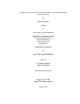
8
Conclusions
A prototype Controller Modelling Program (CMP) has been developed and
implemented. This program provides a graphical means of building control models
using diagrammatic component symbols to create the familiar block diagram
representation of the controller. Components are connected using orthogonal lines,
can be aligned with each other, and can be individually viewed and edited using
property dialogs. Tables have been created to allow the parameters of all the
elements of a particular type to be modified. The block diagram itself can be moved,
panned and zoomed. The controller can then be saved to and loaded from disk in a
plain text format file. The CMP is intuitive and easy to use.
The architecture, API and core analysis engine of a Controller Modelling Engine
(CMEngine) has been developed, implemented. The API and interface layers have
been documented. The engine has been embedded in the CMP to provide an openloop test facility to check the isolated operation of the controllers in response to step
functions.
The IPSA+ power analysis program has been extended to use the new CMP
controller models, and the CMEngine has been integrated into the Transient
Stability analysis section. The existing IPSA+ embedded generation models have
been developed to support I/O signals to and from the new CMP control models.
The CMEngine results have been incorporated into the main IPSA+ transient
stability reporting process to provide full network and controller results on demand.
Direct links have been made from IPSA+ to the CMP program itself to allow simple
and effective access to view and modify the models as required. The CMP has been
christened UDM+ to match the naming convention of IPSA+.
The seamless integration of the CMEngine and subsystems of the CMP inside
IPSA+, and the tight coupling of IPSA+ with the UDM+ program provides a very
powerful toolset to develop and model controllers for embedded generation. The
stability simulation of the example system and control models proves the viability of
this approach and demonstrates its ease of use.
The UDM+ application marks a major improvement in the ability to easily represent
and develop controller models for new and renewable generation. The fast
development time means a large number of different controller variations can be
developed and tested, not in isolation, but on real power system networks with new
and conventional generation represented.
The widespread use of IPSA+ throughout the UK DNO’s should ensure that these
new facilities will be used effectively once the software has been upgraded to
commercial status later this year.
The CMEngine itself is a vendor neutral modelling solution; it is in no way tied to
IPSA+ but has the potential to be embedded in other projects or products, including
other power system stability simulation tools
Page 36
Facilitating the Modelling of Embedded Generation
9
References:
1. “CMEngine Reference Manual version 1.0”, June 2004.
2. “IPSA+ User Manual version 1.3”, December 2004.
3. E. Gamma et al., “Design Patterns: Elements of Reusable Object-Oriented
Software” Addison Wesley, 1999.
4. N. Josuttis, “The C++ Standard Library: A tutorial and Reference”, Addison
Wesley, 2000.
5. Ekanayake, J.B., Holdsworth, L., Jenkins, N. “Control of Doubly Fed Induction
Generator (DFIG) Wind Turbines”, IEE Power Engineer, February 2003, pp 2832.
6. J Arrillaga and C. P. Arnold, “Computer Modelling of Power Systems”; John
Wiley 1990.
7. A. Heath, “Simulation of Generalised Power System Controllers”, PhD Thesis,
UMIST, 1985.
8. S. Khousari, “Interactive User Defined Equipment Modelling in Power System
Analysis”, PhD Thesis, UMIST, 1987.
Page 37