1
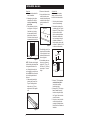
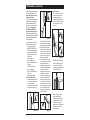
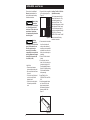
®
TM
WORKCENTERS™
INSTALLATION
MANUAL
A BRIGHT NEW WAY TO WORK. ™
Instruction Manual should be left with end-user.
®
InterMetro Industries Corporation
North Washington Street, Wilkes-Barre, PA 18705
For Product Information Call: 1-800-433-2232
Visit Our Web Site: www.metro.com
INSTALLATION
MANUAL
For the Workcenters™ System
WELCOME
Welcome to InterMetro Starsys WorkCenters™. Starsys WorkCenters
is one of the most design-friendly and flexible systems available.
Starsys WorkCenters’ unique and state-of-the art design allows for
various room configurations based on a small group of key products.
Because of the unique design, your system has been specially
ordered based on your room layout and your end-user’s needs.
The installation guide contained in this manual are general guidelines
for installing the product. We recommend you read and carefully
follow all of the instructions and safety information as detailed in this
manual. Since each installation is unique and custom-ordered, some
of the instructions may not apply to your installation.
This installation Manual contains important information about
preparing a room for installation, the general installation of product,
and important safety precautions necessary to ensure installer/user
safety and prevent product damage. For additional and detailed
information about installing product accessories, please see the
“User’s Guide” supplied with each base unit, tall unit, or overhead
unit. Since every installation is uniquely configured to fit a specific
room layout, you may
encounter installation questions
that are not detailed within this
manual. If this is the case,
please feel free to contact our
technical support department at
1-800-433-2232 for assistance.
TABLE OF CONTENTS
GENERAL SAFETY INFORMATION ............................................3
TOOLS AND MATERIALS..............................................................4
UNPACKING AND IDENTIFYING PRODUCT ..............................5
INSTALLATION ........................................................................6-15
Mark Walls ................................................................................6
Install Overhead Units ..............................................................7
Prepare Base Units ..............................................................8-9
Removing/Installing Drawers or Shelves ............................8
Stage Base Units ............................................................8-9
Adjusting Leveling Feet ......................................................9
Install Trim Kits ......................................................................10
Install Countertops ............................................................11-12
Splicing Countertops ........................................................11
Attach Backsplashes and Sidesplashes............................12
Attach Countertop-to-Wall Brackets ..................................12
Install Base Units ....................................................................13
Attach Countertop to Base Unit .................................. 13
Install Tall Units ......................................................................14
Install Trim Kits in Tall Units ..............................................14
Finishing..................................................................................15
GENERAL SAFETY INFORMATION
The InterMetro Starsys
WorkCenters™ are a safe, convenient product when assembled and
used properly. However, as with
any product, certain safeguards
must be observed—both during
installation and during use. It is
your responsibility to assemble
and install your Starsys
WorkCenters correctly. Also, to
ensure on-going safety, you must
leave a copy of this manual with
the end-user for future reference.
The following symbols will be used
throughout this manual to identify
safety hazards and the risk level associated with the hazard statement.
When a symbol heads a group of
statements, that symbol should be
considered for all of the statements
that follow within that grouping.
DANGER
•
WARNING
•
•
DANGER
Indicates an imminently hazardous
situation which, if not avoided, will
result in death or serious injury.
Observe location of and follow
all local codes for HVAC,
plumbing, gas, oxygen, electrical or phone wiring and/or
boxes.
•
WARNING
Indicates a potentially hazardous
situation which, if not avoided, could
result in death or serious injury.
•
CAUTION
Indicates a potentially hazardous
situation which, if not avoided, may
result in minor or moderate injury.
•
•
Failure to follow any of the
safeguards listed in this manual could result in serious
injury or property damage.
Read all of the information in
this manual before installing
product.
Mounting hardware is not supplied, due to the various types
of wall construction on which
the product may be mounted.
It is the installers responsibility to ensure that the mounting
hardware will support the
weight of the product and its
contents (in lbs.).
Take all safety precautions
when using tools to install
product. Serious injury or
death could result. Please refer
to the manufacturer's instructions for important safety information when using tools.
Use proper lifting techniques
when handling product.
Serious injury could result. Do
not use product top to lift or
carry product. Always carry
product from bottom. For
heavier product pieces, please
use the appropriate number of
people or equipment to lift and
place product.
DO NOT use any hardware or
accessories not recommended
by the hardware manufacturer
for this application. Serious
injury or product damage
could result.
DO NOT exceed maximum
•
•
•
•
•
weight capacity for product.
Doing so could cause personal injury or property damage.
DO NOT stand or sit on product or countertops. Serious
injury could result. Use product only as recommended by
the manufacturer.
DO NOT open more than one
drawer or shelf at a time.
When moving product which
has shelves or drawers
already installed, be sure all
shelves or drawers are closed
and, if applicable, the locking
mechanism engaged.
DO NOT remove back panel
from base units. The back
panel is a required structural
support for the unit.
DO NOT exceed an unsupported countertop span of greater
than 42" (1,067 mm).
Installers should always wear
the appropriate safety equipment (shoes, glasses, gloves,
etc.) when installing product.
CAUTION
•
•
•
Use care when opening and
removing product from shipping cartons. Using a razor,
utility knife, or other sharp
object could result in injury
and/or product damage.
DO NOT place tools or other
installation items onto product
during installation. Product
damage could result.
DO NOT move stationary
product by pushing across
floor. Floor or product
damage could occur. Use
appropriate furniture or heavyitem moving equipment (not
supplied) to transport product.
3
TOOLS AND MATERIALS
The following list details tools and materials needed for a standard
installation. Depending on your installation, additional tools or materials
may be required. Please prepare all tools and materials before attempting installation. Although the tools are listed in general categories, some
tools or materials may be needed for more than one installation step.
Hardware Items Supplied:
Countertop installation
(Intermetro Countertops only)
• #6 fine x 1" (25 mm) countertop
screws (8 per base unit; 8 per
splice bracket)
• Countertop biscuits and T-bolts
(corner only)
Hardware Items Not Supplied:
Mark Walls
• Measuring tape
• 2-3 foot level
• Chalk/chalk line
• Pencil(s)
• Stud finder
Filler Strip Installation
• Utility knife
• Pliers
• Mounting hardware (or double
sided tape) for wall guide
Base Unit and Overhead Install
• Drill (cordless and/or electric)
with drill and driver bits (metal,
wood, and masonry, if necessary)
• Screwdriver set (Phillips, slotted,
and Torx—size T15 and T20)
• Safety glasses
• Wall-mounting hardware (i.e.,
screws, anchors, mollies, etc.)
• Open-end wrench set
• Hole saws (various sizes)
Countertop Installation
•
•
•
•
•
•
•
•
•
•
•
4
Socket wrench set (9/16")
Allen wrench set
Compass
Belt sander
Circular saw
Rubber mallet
C-Clamps (misc. clamps)
Caulk/caulk gun
Hack Saw
Miter Box
Jig Saw
UNPACKING AND IDENTIFYING PRODUCT
• Check that all product has
been ordered and the shipment received.
If possible, we recommend you
confirm product shipment
against the original purchase
order. Double check that all
product ordered has been
received. All shipping cartons
are clearly marked with the following information:
—Product I.D.
—Purchase Order
Number (P.O.#)
• Review site layout plan.
If your installation has minimal
product (1-3 pieces) a site layout plan is not required. For
large installations with more
than 3 pieces, a site layout plan
is required before attempting
installation. A site layout plan
should have been completed
before or during the preliminary
design stages/ordering. If you
do not have a site layout plan
for each large installation,
please contact the appropriate
personnel to retrieve the site
layout plan(s).
• Observe location of HVAC,
plumbing, gas, oxygen, electrical or phone wiring and/or
boxes. (See Figure 1.)
Figure 1
Check that wiring, plumbing,
gas, oxygen, and electrical or
phone boxes are accounted for
in site layout plan. If necessary,
contact qualified personnel to
re-route wires and/or re-locate
items prior to installation.
• Confirm field measurements.
Observe room layout for
obstructions or changes in room
layout. Confirm all field measurements and verify against
site layout plan.
• Stage product for installation(s).
If not already done, organize
product by install location.
Arrange to have each product
grouping delivered to the install
location(s).
• Unpack product.
Use proper lifting techniques
when handling product. Serious
injury could result. DO NOT use
product top to lift or carry product. Always carry product from
bottom. For heavier product
pieces, please use the appropriate number of people or equipment to lift and place product.
product has been thoroughly
unpacked and inspected, dispose
of all shipping materials.
NOTE: You may need to save
packaging materials when making
a claim against a shipping carrier.
• Arrange product.
(See Figure 2.)
Following site layout plan,
arrange product in general vicinity of installation. Note height
and accessory color in assisting
with product recognition.
WARNING
Use care when
opening and
removing product from shipping
cartons. Using a razor, utility
knife, or other sharp object
could result in product damage.
CAUTION
Carefully remove product from
shipping cartons. Place product on
a flat surface and remove protective coverings. Carefully inspect
all packing materials for hardware and product accessories.
For products with a locking module,
be sure keys are taped to top of
locked units. If keys are not
attached to top of unit, carefully
check all packing material for keys.
Inspect all product for shipping
damage. If any damage is noticed,
contact your receiving department
or carrier immediately. Once all
Figure 2
• Determine wall types and
hardware needs.
Determine wall types.
Depending on the wall types,
hardware needs may vary.
Determine and collect necessary hardware for installation.
Mounting
hardware is
not supplied, due to the various
types of wall construction on
which the product may be
mounted. It is the installers
responsibility to ensure that the
mounting hardware will support
the weight of the product and
its contents (in lbs.).
WARNING
5
INSTALLATION - Mark Walls
Base Units
1. Determine which walls will be
used for installation.
2. Measuring only along those
walls which will be used for
installation, determine high
point of floor.
3. Center first base unit on floor
over high point. See Figure 3.
Check that four (4) leveling
feet are retracted and flush
against bottom of base unit.
Use a level to be sure base unit
is square and level on the floor.
5. Remove unit and set aside.
6. Using a chalk line and level,
extend a level line across
mounting hole markings and
continue level line along all
walls for installation. See
Figure 5.
Base Unit Line
Figure 5
7. Reconfirm high point of floor
along all walls for installation.
If a new high point is found,
strike another line based on
the new high point.
High Point
Figure 3
NOTE: Each base unit is shipped
with the leveling feet retracted and
flush against the bottom of the
unit. Although the leveling feet
can be adjusted, you must ensure
that the FIRST base unit has leveling feet flush against bottom of
base unit.
4. Mark mounting bracket hole
locations (slots) on wall. See
Figure 4. Mounting bracket
allows about a 1" (25 mm)
adjustment to fit flush against
wall.
Figure 4
6
8. If the installation has more
than one run of base unit
heights (29"- 737 mm, 35" 889 mm, or 38" - 965 mm),
repeat steps 1-7 for each
height.
Overhead Units
Once base unit line has been
marked, you will need to mark
level lines for all overhead units.
1. Check site plan to determine
location of overhead unit(s).
2. Determine the location of the
overhead unit(s). See Figure 6.
Measure 3/4" (19 mm) up from
short base unit level line to
allow for countertop thickness.
Determine the distance from
top of countertop to bottom of
overhead unit (distance "x").
Mark a reference point on wall
at distance "x" (distance "x" will
be bottom of overhead unit.)
28-1/2"
1"
(724 mm)
(25 mm)
"X"
3/4" (19 mm)
countertop
HIGH POINT
Figure 6
3. Measure 1" (25 mm) up from
marked reference point to
locate bottom mounting
bracket hole height.
4. Measure 28-1/2" (749 mm) up
from 1" mark to locate top
bracket mounting hole height.
See Figure 6. Mark a level line
across this location.
5. Using a level, mark a level line
across both top and bottom
mounting hole height locations.
Mark all walls for overhead unit
installation.
INSTALLATION - Install Overhead Units
If you are referring to a detailed site
plan, we recommend you install all
overhead units before installing base
units. However, in some cases,
installing base units before overheads will allow for more precise
alignment. Please refer to the
Overhead Cabinet User’s Manual
(supplied with product) for product
features and accessory installation
instructions.
2.
Align mounting holes of top
bracket with top line as previously marked on wall.
Mounting holes are slotted to
allow stud installation. See
Figures 7 and 8. Level bracket
and secure to wall using appropriate fasteners.
Mounting
hardware is
not supplied, due to the various
types of wall construction on
which the product may be
mounted. It is the installers
responsibility to ensure that the
mounting hardware will support
the weight of the product and
its contents (in lbs.).
¹⁄₂" (13 mm)
Gap
WARNING
Helpful Hints
• If wall is not plumb, we recommend you shim behind the
mounting brackets as necessary.
• Level mounting brackets before
securing to wall.
• Always verify that mounting
brackets are secure on wall
before hanging overhead units.
1.
Locate mounting brackets for
overhead units. The “top”
bracket has keyhole slots
toward each end and is the
larger of the two brackets. Be
sure top bracket keyhole slots
face up (see Fig. 7).
TOP BRACKET
¹⁄₂" (13 mm)
Gap
28 ¹⁄₂"
724 mm
5.
Figure 8
3.
BOTTOM BRACKET
Figure 7
Align mounting slots of bottom
bracket with bottom line as
previously marked on wall.
Mounting holes are slotted to
allow stud installation. See
Figures 7 and 8. Level bracket and secure to wall using
appropriate fasteners.
Take all safety
precautions
when using tools to install product. Serious injury or death
could result. Please refer to the
manufacturer's instructions for
important safety information
when using tools.
Locate the two shoulder rivets
at the top, rear of overhead unit.
6. Hang overhead unit onto top bracket by aligning and lowering the
shoulder rivets on the rear of the
unit into the two keyhole slots in the
top bracket. See Figure 10. Do not
release overhead unit until you are
certain it is secure on top bracket.
10. Locate the clamp and screw
on the bottom, front of the
overhead unit.
WARNING
4.
KEYHOLE SLOTS "UP"
Figure 9
Repeat steps 1-3 to install
brackets for all overhead
units. Allow a 1/2" (13 mm)
gap between mounting brackets for side-by-side overhead
unit installation. See Fig. 9.
Figure 10
11. Loosen screw and place
clamp under bent flange on
bottom bracket. See figure 11.
Lock clamp into place with
screw.
SIDE VIEW
Figure 11
7
INSTALLATION - Prepare Base Units
Please refer to the product User’s
Manual (supplied inside unit) for
product features and accessory
instructions.
all safety
WARNING Take
precautions
when using tools to install product. Serious injury or death
could result. Please refer to the
manufacturer's instructions
for important safety information
when using tools.
Mounting
hardware is
not supplied, due to the various
types of wall construction on
which the product may be
mounted. It is the installers
responsibility to ensure that the
mounting hardware will support
the weight of the product and
its contents (in lbs.).
WARNING
Helpful Hints
• Begin base unit installation with
unit closest to corner.
• The rear panel of the base units
can be cut with a hole saw to provide access to phone jacks, electrical outlets, etc. Do not remove
back panel. The back panel is a
necessary structural support for
the base unit.
• Be sure mounting holes are on a
level line before securing product
to wall.
• Verify that product is square and
level before attaching base unit to
wall and attaching countertop.
• Always verify that base unit
mounting bracket is secured to
wall before attaching countertop.
• Level and square product so top
and face is flush and square with
previous unit.
Removing/Installing Drawers or
Shelves
4.
For ease of installation, we recommend you remove all or most of the
drawers or shelves from base units.
Attaching the countertop requires
the top drawers or shelves to be
removed. Leveling the base unit
requires the lower drawers or
shelves to be removed. To eliminate confusion, you can remove
drawers or shelves as each base
unit is installed. The drawers can be
re-installed once each base unit is
completely installed. To remove
polymer shelves, simply pull shelf
from inner panels. To remove wire
shelves, please see the "User's
Guide" included inside the actual
product. Base units with doors do
not require that the doors be
removed for installation.
5.
1.
Stage all base units as specified by the site layout plan.
To remove drawers:
2.
Double check that the installation will not interfere with
wiring or other obstacles. If
necessary, contact qualified
personnel to re-route wires
and/or re-locate items prior to
installation.
3.
Place first base unit for installation at desired location. If
the site plan calls for a corner
unit, place first base unit in corner location. See Figure 13.
If base unit has a locking mechanism, locate keys (taped to top of
unit) and unlock drawers.
IMPORTANT: DO NOT remove locking module from unit. The unit will not
work properly without lock module.
2. Pull drawer out until it stops.
3. Press in orange clips located
on both sides of drawer. See
Figure 12.
1.
2.
3.
4.
Slide drawer into inner panels
of base unit.
Be sure drawer stays even
between panels and push
drawer completely back. The
orange clips will automatically
spring into position as the
drawer is pushed back.
Pull out drawer until it stops.
If drawer does not stop, reinstall as instructed in step 2
above.
Repeat to install all drawers.
Stage Base Unit(s)
ORANGE CLIP
Figure 13
ORANGE CLIP
Figure 12
8
To install drawers:
NOTE: Be sure to note positioning
of 3", 6", or 9" (76 mm, 152 mm, or
229 mm) drawer sizes before
removing drawers from base.
1.
Carefully pull out and set
drawer aside.
Repeat steps 2-4 above for all
drawers.
INSTALLATION - Prepare Base Units (Cont.)
4.
Align mounting hole locations
in mounting bracket with chalk
line. See Figure 14.
Adjusting Leveling Feet
The base units can be raised up to
2-1/2" (64 mm) using the adjustable
leveling feet. To access the leveling
feet, the lower drawers or shelves
must be removed from the base
unit. See "Removing/Installing
Drawers or Shelves" for detailed
instructions.
1.
Figure 14
5.
6.
Check that mounting bracket
and product are level and
plumb. If base unit is not level,
you must adjust leveling feet.
See "Adjusting Leveling Feet"
for detailed information before
proceeding.
If desired, use a hole saw to
cut an access hole (phone
jacks, electrical outlets, etc.) in
the rear panel of the base
unit. See Figure 15. Do not
remove back panel. Back
panel is a necessary structural
support for base unit.
2.
3.
4.
5.
Remove lower drawers or
shelves from base unit, if present.
Locate four (4) recessed holes
in bottom of base unit.
Using a slotted screwdriver,
turn the screw to lower or
raise the leveling feet. See
Figure 16. Turn screw clockwise to raise unit; counterclockwise to lower unit.
Adjust each leveling foot as
necessary to level unit.
Once unit is level, place black
plugs (included) into each
hole.
Figure 16
Figure 15
7.
Place second base unit into
position. Repeat for all base
units.
IMPORTANT: DO NOT
ATTACH BASE UNITS TO
WALL AT THIS TIME!
9
INSTALLATION - Install Trim Kits
Corner Filler Strips
1. For 45˚ or 90˚ corner units, lift
and remove flat filler strips
from mating front posts.
2. Slide interlocking strips down
channel on front corner post of
each corner base unit. See
Figure 22.
Trim Kits are optional accessories to
the Starsys WorkCenters™ line.
Refer to the site plan for proper
location of filler strips.
The Trim Kits are designed to aesthetically fill the gap between the
base unit and the backwall or
between two corner units (45˚ or
90˚ angle). It is important to
install filler strips BEFORE
attaching countertops to base
units. Also, installing filler strips
before attaching product to wall will
help align product, especially on
corner installations.
There are three sets of Trim Kits.
Each kit contains the following:
• Unit-to-wall (model nos.
SX39BKFLR, SX72BKFLR;
Trim Kits are supplied longer
than the installation heights.
Trim Kits must be cut to fit.) —
2 Filler Strips
1 pair wall guides
• 45˚ corner filler strip
(model no. SX84CR45FLR) —
1 filler strip
1 pair interlocking strips
• 90˚ corner filler strip
(model no. SX84CR90FLR) —
1 filler strip
1 pair interlocking strips
Unit-to-Wall Filler Strips
1. Measure distance from floor to
top of unit (less countertop).
Cut pieces to length.
2. Carefully slide unit-to-wall filler
strips into channels on rear
45˚ Corner
Figure 20
3.
4.
5.
posts. See Figure 19. Be sure
each filler strip slides straight
down and stays inside channel.
Slide flat side of wall guide
down along wall so wall guide
channel runs over edge of filler
strip. See Figure 20. Once wall
guide is in place, mark wall
along side of wall guide.
Set wall guide in a safe location and move base unit aside.
Reposition wall guide to
marked location and secure to
wall with double-sided tape or
screws (not provided).
Reposition base unit so filler
strip fits inside wall guide.
If necessary, scribe filler strip
to fit into wall guide channel.
Remove filler strip from base
unit. Carefully score filler strip
along marked line with a utility
knife. Using pliers, gently snap
off scored pieces. Replace
filler strip into channel on rear
post. See Figure 21.
90˚ Corner
Figure 22
3.
Figure 23
4.
Figure 19
10
Figure 21
Slide filler strips into channels
on two interlocking strips. Be
sure each filler strip slides
straight down and stays inside
channel. See Figure 23.
Mark "cut" location on filler
strip (at desired height).
Remove filler strip from interlocking channels. Cut filler
strip with a utility knife at
marked location. Replace filler
strip into channels on two
interlocking strips.
INSTALLATION - Install Countertops
Place Countertops into Position
Countertop-to-Countertop
For alignment purposes, we suggest you place all countertops into
position once all filler strips have
been installed.
1. Turn two adjacent countertop
pieces upside down and place
on a smooth, flat surface or on
wood blocks. Take care not to
scratch countertop surface.
2. Place countertop-to-countertop
bracket along seam on underside of two adjoining countertops. Check that all seams fit
together squarely and tightly.
See Figure 25.
1. Place countertops into position
on base units.
2. Align counter bores in underside of countertop with four
bolts on top of base units. See
Figure 24.
bolt is properly installed,
the bolt will stand off about
2" (51 mm) from countertop
edge. See Figure 28.
Figure 28
BOTTOM
VIEW
TOP VIEW
Figure 25
Figure 24
3. Confirm countertop is seated
properly on base units.
4. Check front edge of countertop
pieces. Be sure all edges are
square and flush.
3. Using 8 - 1" (25 mm) x #6 fine
screws (supplied), secure
bracket to underside of countertops. See Figure 26.
5. Place T-bolt retainer, with slot
facing down, into hole over Tbolt head. Use a small allen
wrench to tighten T-bolts and
draw countertop pieces together. See Figure 29. Before fully
tightening T-bolts, check that
all seams and corners fit
together squarely and tightly.
Proceed to tighten corner
countertop pieces together.
Splicing Countertops
DO NOT
exceed an
unsupported countertop span
greater than 42" (1,067 mm). Do
not splice countertops together
within an unsupported span.
WARNING
Some countertop-to-countertop
installations will require splicing.
FRONT VIEW
For straight run
countertops that
meet another
countertop
where there is no base unit (kneehole installation), the countertops
must be spliced together.
Corner counterFRONT VIEW
tops require fastening countertop
pieces together.
Depending upon your installation,
please follow the instructions below
for splicing countertops.
Figure 26
Corner
1. Turn all countertop pieces
upside down and place on a
smooth, flat surface or on
wood blocks. Take care not to
scratch countertop surface.
2. Insert biscuits (supplied) into
aligning slots in sides of cut
countertop. See Figure 27.
Figure 29
6. Place countertop-to-countertop
bracket along seam on underside of two adjoining countertops. See Figure 30. Check
Bracket
Bracket
Figure 27
3. Push countertops together.
4. Screw threaded end of T-bolt
into barrel and drop into slot as
shown in Figure 28. When T-
Figure 30
that all seams fit together
squarely and tightly.
11
INSTALLATION - Install Countertops (cont.)
Attach Countertop Backsplashes
To prevent possible shipping damage, all countertops are shipped flat.
Backsplashes (shipped with countertops) and sidesplashes (optional)
must be attached before countertop
installation.
To attach backsplash onto
countertop:
To attach sidesplash (option)
onto countertop:
Attach Countertop-To-Wall
Brackets
1. Place countertop (finished side
up) on a flat surface (or on
supports as shown). Carefully
run a bead of silicone caulk
onto edge of countertop at
desired side. See Figure 34.
DO NOT
exceed an
unsupported countertop span
greater than 42" (1,067 mm).
1. Place countertop (finished side
up) on a flat surface (or on
supports as shown). Carefully
run a bead of silicone caulk
onto back edge of countertop.
See Figure 31.
2. Note finished and unfinished
edges of backsplash. Place
backsplash (unfinished edge
down) over caulk bead on countertop. See Figure 32. Use
clamps (as necessary) to hold
backsplash in place.
2. Note finished and unfinished
edges of sidesplash. Place
sidesplash (unfinished side
down) over caulk bead. See
Figure 35. Use clamps (as
necessary) to hold sidesplash
in place.
3. From underside of countertop,
secure backsplash to countertop with supplied screws
through holes provided in
countertop. See Figure 33.
TOP VIEW
FRONT VIEW
WALL
TOP VIEW
FRONT VIEW
Figure 37
Figure 35
Figure 32
Countertop-To-Wall Brackets are
used in thefollowing situations
(see Figure 37):
a. When one end of a countertop
is supported by a wall; or
b. To support the back end of a
corner countertop.
Figure 34
Figure 31
WARNING
3. From underside of countertop,
secure sidesplash to countertop with supplied screws
through holes provided in
countertop. See Figure 36.
1. Determine locations where
countertop-to-wall brackets will
be required.
2. Attach wall bracket to wall 3/8"
(10 mm) below base unit line
with appropriate fasteners.
Note proper orientation of
bracket (flat "support" side of
bracket is against underside of
countertop). See Figure 38.
3/8" (10 mm)
Figure 38
Figure 36
Figure 33
12
3. Once countertop is in place,
attach bracket to countertop
with appropriate hardware.
Stud mounting is preferred
whenever possible.
INSTALLATION - Install Base Units/Attach Countertops
Mounting
hardware is
not supplied, due to the various
types of wall construction on
which the product may be
mounted. It is the installers
responsibility to ensure that the
mounting hardware will support
the weight of the product and
its contents (in lbs.).
WARNING
Wall mounting the base units is the
recommended installation method.
However, in some installations, it
may be necessary to floor-mount
the base units. If this is the case,
please contact your local InterMetro
representative and request part
number "SXFLR" to order an
optional floor mounting kit. All floor
mounting instructions are included
with floor mounting kit.
1. Once all countertops are set in
place on base units, carefully
adjust base units (if necessary). This will be the final
adjustment before securing
base units to wall.
2. Remove and set aside all
countertops.
3. Using the appropriate fasteners, secure all base units to
wall through mounting bracket.
Stud mounting is preferred
whenever possible. See Figure
39.
Attach Countertop to Base Units
1.
2.
Place countertop into position
over base units.
Adjust countertop to fit counter
bores over base unit top bolts
(4). See Figure 40.
Figure 40
5. Once all countertops are properly aligned, from inside base
units attach countertop to base
with supplied screws (#6 fine x
1" - 25 mm). For single wide
bases, use 4 screws. For double wide bases, use 8 screws.
See Figure 41.
yyyyyyyy
;;;;;;;;
;;;;;;;;
yyyyyyyy
;;;;;;;;
yyyyyyyy
;;;;;;;;
yyyyyyyy
;;;;;;;;
yyyyyyyy
Figure 41
3.
Confirm countertop is seated
properly on base units.
Take all safety
precautions
when using tools to install product. Serious injury or death
could result. Please refer to the
manufacturer's instructions for
important safety information
when using tools.
CAUTION
4.
Check wall edge of countertop. If desired, scribe backsplash edge to wall.
4. Repeat for all base units.
Figure 39
13
INSTALLATION - Install Tall Units
Please refer to the unit User’s
Manual (located insideunit) for
product features and accessory
installation instructions.
1.
Stage all tall units as specified
by the site layout plan. See
Figure 43.
Take all safety
precautions
when using tools to install product. Serious injury or death
could result. Please refer to the
manufacturer's instructions
for important safety information
when using tools.
WARNING
Figure 43
Mounting
hardware is
not supplied, due to the various
types of wall construction on
which the product may be
mounted. It is the installers
responsibility to ensure that the
mounting hardware will support
the weight of the product and
its contents (in lbs.).
CAUTION
2.
3.
4.
Helpful Hints
• Remove lower drawers or
shelves to adjust leveling feet.
• Be sure level unit before securing to wall.
• Use a level to verify that product is level on floor before
attaching to wall.
• Position units so front edge is
flush and square with base
units.
5.
6.
Double check that the installation will not interfere with
wiring or other obstacles. If
necessary, contact a qualified
professional to re-route wires
and/or re-locate items prior to
installation.
Position Tall Unit in desired
location.
Check that unit is level and
plumb. If tall unit is not level, you
must adjust leveling feet. See
"Removing/Installing Drawers or
Shelves" and "Adjusting Leveling
Feet" for detailed information
before proceeding.
Install Filler Kits. See
"INSTALLATION—Install Trim
Kits."
Using the appropriate fasteners, secure tall unit to wall
through mounting bracket.
Stud mounting is preferred
whenever possible. See
Figure 44.
Figure 44
14
Installing Trim Kits in Tall Units
(Optional Accessories)
Trim Kits are accessories to the
Starsys WorkCenters line. They
are ordered separately as an
option to the Tall Units. Filler
strips install the same way for both
Base Units and Tall Units, except
tall unit filler strips are longer in
length to accommodate the height
of the Tall Unit. Please see
"INSTALLATION—Install Trim Kits"
section for detailed filler strip
installation instructions.
INSTALLATION - Finishing
Finishing Products
Cove Moulding:
If desired, the front of the base
units can be finished with vinyl
cove moulding. Cove moulding is
available at local hardware stores.
See recommended installation
instruction supplied with cove
moulding.
Sinks:
If you are installing a sink, sinks
and their accessories are available
at local hardware stores. Please
contact a licensed plumber for sink
installation. Be sure all plumbing
codes are followed when installing
a sink. An InterMetro Sink
Valance Panel is available to finish
off the front of the unit when
installing a sink. Please contact
your InterMetro representative to
order any sink accessories. All
installation instructions are supplied with sink accessories.
Clean-Up
Always clean product before leaving installation site. Clean all
product with a soft cloth dampened with water and a mild detergent. DO NOT use harsh or abrasive chemicals to clean product as
this may damage the product surface. Dry immediately with a soft
cloth.
Countertop Cleaning:
The countertop's decorative surface may be cleaned with warm
water and mild detergents such as
those used for hands or dishes.
DO NOT use cleansers which contain abrasives, acids, or alkalines,
as they will damage the decorative
surface. Remove stubborn stains
with a 2-minute exposure to
hypochlorite bleach such as
Clorox, followed by a clean water
rinse.
The cleaning products listed below are suitable for cleaning the
product body, drawers, and accessories.
CLEANER BASE
DESCRIPTION
PRODUCT EXAMPLES
Phenol
Liquid detergent, disinfectant, deodorizer
Amphyl
Chlorine
Liquid disinfectant
Bleach
Alkaline
Liquid detergent
Liquid detergent
Conquer II
Prime
Alcohol
Antiseptic sterilizer
Isopropyl Alcohol
Iodophor
Liquid germicide detergent
Accord
Quaternary Ammonia
Compound
Liquid detergent, disinfectant
Liquid detergent, disinfectant
Liquid detergent, germicide, deodorizer
Foam cleaner, disinfectant
Liquid detergent, disinfectant
FSD-4
Spartec
Micro-Quat
Spra-Temp
Lysol 256
15
Warranty
WARRANTY, EXCLUSION OF WARRANTIES AND LIMITATION OF LIABILITY. InterMetro
Industries Corporation (hereinafter referred to as “Seller”) warrants to the original
purchaser that all products in its catalog, or custom products, delivered hereunder will
be free from defects in workmanship and material. THE FOREGOING WARRANTY IS
EXCLUSIVE AND IN LIEU OF ALL OTHER WARRANTIES, EXPRESS, IMPLIED OR
STATUTORY, INCLUDING ANY WARRANTY OF MERCHANTABILITY OR FITNESS FOR A
PARTICULAR PURPOSE. This Warranty shall be for a period of one (1) year from the
date of shipment from Seller’s warehouse or factory. If any product delivered hereunder
does not meet the Warranty specified above, providing the product has not been
altered in any way by anyone other than Seller’s factory-authorized representative, and
assuming normal and proper use and maintenance, Seller will, at its option, repair or
replace any part or material it determines, upon inspection, to be defective; provided,
however, that a charge for labor will be made except during a period of ninety (90) days
from the date of original shipment from Seller’s warehouse or factory. No product, or
part thereof, is to be returned to Seller without prior written approval from Seller’s
factory. All exchanges and replacement shipments will be F.O.B. Seller’s factory.
Warranties for equipment or articles not manufactured by the Seller are solely the
warranties of the manufacturers thereof and they are hereby assigned to the purchaser
without recourse to the Seller.
SELLER’S LIABILITY FOR ANY CLAIM OF ANY KIND, WHETHER BASED ON CONTRACT,
NEGLIGENCE OR STRICT LIABILITY IN TORT, AND BY WHOMEVER MADE, FOR ANY
DIRECT, INDIRECT, INCIDENTAL OR CONSEQUENTIAL LOSS, DAMAGE OR INJURY,
RESULTING TO THE PURCHASER OR ANY THIRD PARTIES, arising out of, connected
with or resulting from this Agreement, or from the performance or breach thereof, or
from the manufacture, sale, delivery, resale, installation, inspection, repair or use of any
product covered by or furnished under this Agreement, WHETHER OR NOT CAUSED BY
SELLER’S NEGLIGENCE, SHALL IN ALL EVENTS BE EXCLUSIVELY LIMITED TO THE COST
OF CORRECTING DEFECTIVE, DAMAGED OR NON-CONFORMING PARTS OR MATERIAL
AS HEREIN PROVIDED, and upon the expiration of one (1) year, all such liability shall
terminate.
SELLER DOES NOT AUTHORIZE any person to assume for it any obligations or liabilities
greater than or different than those set forth in this Warranty. The terms under which
any of Seller’s products may be resold must be limited in accordance with this Warranty.
THIS AGREEMENT, and all the rights and obligations arising hereunder, shall be
construed in accordance with, and be governed by, the law of the Commonwealth of
Pennsylvania, U.S.A.
®
InterMetro Industries Corporation
Wilkes-Barre, PA 18705
10/83
Starsys...
improving the way professionals work.
Create a more functional and
effective storage, organization
and workspace that’s just right
for today. Then re-create it for
the needs of tomorrow.
For more information on the
Starsys Line of product, call
your Metro Product Specialist at
1-800-433-2232.
®
TM
ISO REGISTERED
9
0
0
1
-
9
0
0
A BRIGHT NEW WAY TO WORK.
™
2
Information and specifications are subject to change
without notice. Please confirm at time of order.
www.metro.com
L01-292
Rev. A
7/99