1
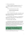
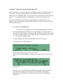
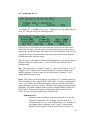
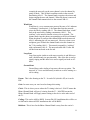
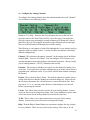
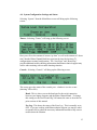
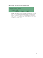
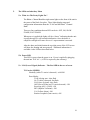
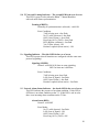
1. IMPORTANT STUFF
The RhinoTM channel bank comes ready to go. This section describes important
information you need to know with regard to the warranty and safety information.
1.a. Warranty
The RhinoTM Channel Bank is covered by a 5 year limited factory
warranty. This warranty is very simple and straightforward. For a
complete description of the 5 year limited factory warranty refer to the
warranty certificate which came with the unit. If you would like another
copy of the warranty certificate contact Rhino Equipment Corp.
1.b. Standards
This equipment complies with Part 68 of the FCC Rules. The FCC Part
68 Label is located on the side of the enclosure. This label contains the
FCC Registration Number for this equipment. If requested, this
information must be provided to your telephone company.
Connection to the telephone network should be made by using standard
modular telephone jacks, type RJ48C. The plug and/or jacks used must
comply with FCC Part 68 Rules.
OPERATION
T1 CSU Interface
FIC
04DU9-1SN
04DU9-1ZN
SOC
6.0N
(USOC) JACK
RJ48C
If this telephone equipment causes harm to the telephone network, the
telephone company will notify you in advance that temporary
discontinuance of service may be required. But if advance notice isn’t
practical, the telephone company will notify the customer as soon as
possible. Also, you will be advised of your right to file a complaint with
the FCC if you believe it is necessary.
The telephone company may make changes in it’s facilities, equipment,
operations or procedures that could affect the proper functioning of your
equipment. If they do, you will be notified in advance in order for you to
make necessary modifications to maintain uninterrupted service.
If trouble is experienced with this unit, please contact customer service at
the address and phone listed below. DO NOT DISASSEMBLE THIS
EQUIPMENT. It does not contain any user serviceable components.
1
Contact:
Rhino Equipment Corp
Attn: CUSTOMER SERVICE DEPT.
159 S. Lincoln, Suite 221
Spokane, WA 99201
Ph 509-847-0700, Fax 509-847-3947
1.c. Surge Protection
It is recommended that a surge protector or un-interuptible power supply
(UPS) be installed between the RhinoTM Channel Bank and the AC outlet to which
it is connected. This will help minimize damage as a result of lightning strikes
and other AC line surges. Failure to use a UPS could affect the 5 year limited
warranty.
2
2. INSTALLATION
TM
2.a. Unpacking the Rhino Channel Bank
The unit comes in a very sturdy shipping box. The package contains the
RhinoTM channel bank, 110V ac power cable, T1 and Analog cables and
accessories.
Check the materials in the box against the following packing list. Inspect
the unit for any signs of physical damage. Report any damages to the
shipper. Keep all packaging material in the event that you need to move
or ship the unit in the future. Warranty returns must be shipped back to
Rhino Equipment Corp in the original shipping box and included insert.
Packing List
Description
Quantity
RhinoTM channel bank
1
Wall-Mount brackets (already attached to the unit)
4
110 V right angle ac input power cable
1
T1 Network Cable, RJ48C to RJ48C
2
RhinoTM Channel Bank Warranty Card
1
RhinoTM Channel Bank Warranty Certificate
1
RhinoTM Channel Bank User's Manual on CD
1
25 Pair Analog connector cable (female to female)
1
2.b. Site Selection
The installation site should provide enough space for adequate ventilation
and cable placement. You need to allow 3-4 inches of space on the sides,
above and below to insure there is adequate air flow. Provide enough
space from the black side panel for access to the LCD screen and the red
programming buttons.
The selected installation site should provide a stable operating
environment. The area around the installation site should be clean and
free from extremes of temperature, humidity, shock, and vibration. The
operating temperature should be kept below 100 degrees F.
The RhinoTM channel bank is designed to be used on T1 (DS1) service
only. Connecting it to any other type of telecommunications service or
services will void the warranty and could cause damage to the network of
the provider of the non-approved service or services.
3
All wiring done external to the RhinoTM channel bank should follow
the guidelines as set forth by the National Electrical Code.
2.c. Physical Installation
The RhinoTM Channel Bank is intended to be installed on the wall as a wall
mounted unit or in a standard 19 inch rack mount environment or standard 23”
rack mount environment. Failure to install the unit in one of these configurations
will effect the warranty on the unit. The “L” brackets that came with the unit can
be easily moved to reconfigure the unit to meet the installation environment you
have chosen.
If the RhinoTM Channel Bank is mounted to the wall be sure to use
appropriate screws and/or fasteners suitable for mounting heavy objects.
The RhinoTM channel bank weighs just under 20 pounds. Masonry
mollies, #8 or larger wood screws or expansion bolts should be used. Do
not attempt to install the unit on a wall which may not support the weight
of the unit.
2.d. Power Connection
It is recommended that the unit be plugged into a UPS, which is then
plugged into a standard 110V AC plug (in the wall). The unit is grounded
on the third prong of modern grounded a.c. building wiring. This is
sometimes called "Green Wire" ground. This is the safety grounding point
used by the RhinoTM Channel Bank 110Vac Power Supply. As long as
the unit is plugged into a properly wired 3 prong outlet the unit will be
properly grounded. Failure to use a UPS could allow lightning to damage the unit
and this is NOT covered by the warranty.
4
3.
T1 INSTALLATION
3.a. Connecting the T1
T1 Cable Installation
The RhinoTM Channel Bank T1 (DS1) interface is an industry-standard
RJ48C 8 pin connector with its connections described below. The T1 is
usually connected to the telecommunications carrier demarcation point.
This is the point at which the carrier terminates their T1 at the customer's
premise. Use the included T1 cable to connect the unit to the demarcation
point. In some cases additional cable must be run from the carrier’s
demarcation point to the customer’s suite or nearby “phone room”.
T1 Line Interface on RJ48C - 8 pin Modular T1 jack
Pin Number
1
2
3
4
5
6
7
8
Signal
Receive Ring
Receive Tip
Not connected
Transmit Ring
Transmit Tip
Not connected
Not connected
Not connected
To/From What?
Coming From T1 (Network)
Coming From T1 (Network)
Going To T1 (Network)
Going To T1 (Network)
The maximum cable length for a T1 Network (DS1-1) connection is
suggested as follows. Reliable T1 cabling distances depend on which type
of cable is used. It is strongly recommended that only shielded cable be
used as part of any T1 installation. For best results use: shielded 22 AWG
T1 cable (ABAM 600).
ABAM 600 T1 Cable
T1 Network (CSU)
can go as far as 6,000 feet
ABAM 600 Cable Specifications:
Nominal Impedance: 100 ohms +/- 5% at 772 kHz.
Insertion Loss:
Better than 7 dB per 1,000 feet at 1.544 MHz.
Better than 5 dB per 1,000 feet at 772 kHz.
Far-End Crosstalk: Better than 85 dB per 1,000 feet at 1.544 Mhz.
Better than 90 dB per 1,000 feet at 772 kHz.
Near-End Crosstalk: Better than 80 dB per 1,000 feet at 1.544 Mhz.
Better than 85 dB per 1,000 feet at 772 kHz.
5
Shields:
Transmit and receive pairs are individually
shielded with aluminum/polyester tape.
If you used unshielded cable you could experience problems. When this
type of cable is used, transmit and receive pairs are usually run in separate
cables to avoid crosstalk which often occurs in unshielded cables. Failure
to use separate cable bundles for transmit and receive can result in the
CSU LINE port clocking onto itself (due to crosstalk) with as little as 10
feet of unterminated (unshielded) telephone cable attached. The CSU can
thus show a normal framed status when the far end of the telephone wiring
is actually disconnected. Again, this is due to crosstalk between pairs in
the same cable bundle. This is true of any CSU installation using any
kind of unshielded twisted pair cable.
RhinoTM Included T1 Cable
RhinoTM to Network - 10 feet
Connectors
RJ48C to RJ48C
3.b. Connecting the 24 Analog Channels
25 Pair Analog Cable
The RhinoTM Channel Bank has a 25-Pair Female Telephony Connector.
This connector is on the back of the unit. To connect to it, use a 25 pair cable
with a Standard "D" Style 50 Pin Telephone Wiring Connector with RJ-21X
wiring jack (punch down block with 25 pair modular female connector in the
side.) For your convenience a cable of this type comes with the RhinoTM Channel
Bank.
Pin Location
26
1
27
2
*
*
*
49
24
Function
Tip Channel 1
Ring Channel 1
Tip Channel 2
Ring Channel 2
*
*
*
Tip Channel 24
Ring Channel 24
Note: The RhinoTM channel bank utilizes only 24 pair of the available
25 pair in the analog cable assembly.
6
3.c. LCD Screen and What It Means
The RhinoTM Channel Bank is equipped with an LCD screen which is
used to display the signaling bits (the A and B bits). These bits are
displayed in real-time (within a few milliseconds) and they are displayed
all the time.
The format of the display of these bits is as follows:
XXXXXXXXXXXXXXXXXXXXXXXX
XXXXXXXXXXXXXXXXXXXXXXXX
where “X” can be 1, 0, A, B or R.
The top row of digits displays what the RhinoTM Channel Bank is receiving
from the network. The bottom row of digits displays what the RhinoTM Channel
Bank is transmitting out to the network. Channel one is to the far left and
channel twenty-four is to the far right.
A “1” means both the “A” and “B” bits are 1. A “0” means both the “A”
and “B” bits are 0. An “A” means the “A” bit is 1 and the “B” bit is 0. A “B”
means the “B” bit is 1 and the “A” bit is 0. “R” means the channel bank is
applying ring voltage to the analog channel.
3.d. Programming the Rhino Channel Bank
Programming the Rhino Channel Bank is done with the four red buttons
just below the LCD screen. The buttons are “locked” in order to safeguard an
accidental change in the configuration. In order to “unlock” the programming
buttons you will need to press them in the following sequence: 1 3 2 4
(counting from the left). As you push each one you will see an asterisk (*) appear
above each button. If you make a mistake wait for a short time while the
password feature resets itself and you can then try again. The main screen will
look like the following as the system initials itself.
Once the Rhino Channel Bank has initialized itself – if the T1 is not connected (or
T1 carrier is not found) the following screen will appear:
7
If, however, the T1 is connected and T1 carrier is recognized by the unit you will
see the following screen:
Once you press the four programming buttons in the correct order as described
above you will see the following screen:
Now you are ready to configure the Rhino Channel Bank.
8
4. RHINOTM CHANNEL BANK CONFIGURATION
All configurations are set easily using the 4 red buttons which are located just below the
LCD screen. The programming screen is password protected so that unintentional
changes are not accidentally made. The password is to press the buttons in the following
order: 1 3 2 4 (counting with the far left button as #1 and to the far right as #4).
Once you are past the password into the programming screen from there it is very
intuitive. (For a tutorial simply run the tutorial program that came on the same CD that
this document came on.)
4.a. AUTO T1 Configuration
The AUTO T1 Configuration of the RhinoTM Channel Bank makes it the
easiest channel bank on the market to set up and configure. Simply plug in the
unit and it will self configure according to what the T1 has been set up for. If the
T1 is not yet turned up by the carrier simply go into Config and then select AUTO
T1. The unit will reconfigure itself.
To Auto Configure select the red button under the word “Configure”.
You will then see the following screen:
The press the red button under the word “AutoT1”.
Then press the fourth red button to confirm you wish to run the Auto T1 config
tool.
It’s that easy!!
(If the T1 is set up for Immediate or Wink start you might need to run AutoT1
more than once to make sure it properly “sees” the correct configuration.
Immediate Start and Wink Start “look” almost identical from a signaling bit
standpoint.)
9
4.b. Configuring the T1
To configure the T1 manually is very easy. Simply press the red button under the
word “T1” and you will get the following screen:
From here the first red button (the one on the left) will move the cursor to the
Next Field (Nxt Fld). Once the cursor is located at the field you want to setup
pressing the second red button will Change the Value of that field (Chg Val). By
using the first and second red buttons you can navigate between each field and
scroll through each available setting.
The following is a description of each field (although this is very intuitive and you
might not need to read this section – it is here for those not familiar with T1
configurations).
Slot: This references the “channels” on the T1. There are 24 of them. You can
configure ALL of them or you can step through each one and configure each
channel separately. (Keep in mind you are configuring T1 channels – NOT
analog channels in this screen).
Proto: This references the start protocol you want to use. Available options are
Wink, Immediate, Loop, Ground, DID1, DID2, DID3. If you are setting up DID
service you will need to call for tech support so that you can make sure all the
timing parameters are set up correctly. Different carriers approach DID protocols
differently. The Rhino Channel Bank is flexible enough to handle virtually any
DID protocol. Sometimes getting the timing right in some instances can be
tricky. Here is a description of the other start protocols:
Immediate Start
Immediate Start is the oldest of the start protocols. It is also the
simplest to understand. The “transmit” from the network is
connected to the “receive” of the channel bank. The “transmit” of
the channel bank is connected to the “receive” of the network.
Immediate Start begins by having one end of the circuit (in our
10
example the network), on the same channel, seize the channel by
going off hook. This off-hook condition results in the network
transmitting AB=11. The channel bank recognizes the seizure and
begins ringing the near end channel. When the phone is answered
the channel bank transmits back to the network AB=11.
Wink Start
Wink Start is a very common start protocol because of it’s inherent
“confirming” characteristic. Like Immediate Start the network
seizes the line by sending AB=11. The channel bank then “winks”
back at the network by sending a momentary AB=11. This
confirms” to the network that the seizure was recognized. The
channel bank rings the phone corresponding to the seized channel.
When the phone is answered the channel bank sends the network
AB=11 indicating the call was answered. Likewise, when a near
end phone goes off-hook the channel bank seizes the channel on
the T1 by sending AB=11. The network responds by “winking”
with a momentary AB=11. The network sends AB=11 after the
call has been answered at the far end.
Loop Start
Loop Start works similar to wink start except the A and B bits are
used a bit differently (no pun intended). One of the bits is used to
signify ringing and the other bit is used to signify on-hook or offhook.
Ground Start
Ground Start works similar to loop start with one exception. The
network “A” bit is used differently to indicate a call is starting or a
call is ending.
Frame: This is the framing on the T1. It can be D4 (which is SF) or it can be
ESF.
Gain: In most cases you won’t need to change this setting.
Clock: This is where you set where the T1 timing is derived. SLAVE means the
Rhino Channel Bank will gets it’s timing from the T1. MASTER means the
Rhino Channel Bank will supply master timing to the device at the other end of
the T1.
Coding: This can be AMI or B8ZS. In most D4 (SF) installations this will be set
to AMI and in almost all ESF installations this will be B8ZS.
Buildout: This is how far the Rhino Channel Bank is away from the carrier’s
11
demarc point (in feet). If you are within 133 feet of the demarc then you won’t
need to change this setting.
Once your changes have been made you MUST save them by pressing the
third red button. If you do NOT save them – the changes will NOT go into
effect. To exit this area without saving OR after saving press the fourth red
button to go back to the previous screen.
12
4.c. Configure the Analog Channels
To configure the Analog channels press the red button under the word “Channel”.
You will then see the following screen:
Similar to T1 Config - from here the first red button (the one on the left) will
move the cursor to the Next Field (Nxt Fld). Once the cursor is located at the
field you want to setup pressing the second red button will Change the Value of
that field (Chg Val). By using the first and second red buttons you can navigate
between each field and scroll through each available setting.
The following is a description of each field (although this is very intuitive and you
might not need to read this section – it is here for those not familiar with analog
channel configurations).
Channel: This references the analog “channels” on the analog side of the Rhino
Channel Bank. There are 24 of them. You can configure ALL of them or you
can step through each one and configure each channel separately. (Keep in mind
you are analog channels – NOT T1 channels in this screen).
Function: This references whether you want to use the channel for analog voice
or for data. If you select data you have nothing more to set in this screen as that is
programmed in a different screen. If you select ANLOG then continue setting up
the channel.
PwrDn: This is short for Power Down. This tells the channel to actually remove
voltage from the line when the channel goes on-hook (hangs up). Many telecom
devices do not disconnect the call unless power is removed from the line. Here
you can set 1, 2, 3 or 4 seconds as the duration of time that power is removed
before re-powering the channel.
I-Loop: This is how much current is used to drive the analog channel. In most
cases you won’t need to change this setting. But if your installation requires more
or less line current for the analog channel you can set the value here.
Tx Rx: This is where you set the transmit and receive gain for the analog
channel. In most cases you will not need to change this setting.
Ring: With the Rhino Channel Bank you can custom configure the ring cadence
for every channel. There are two values for this setting. Each value is in 100
13
millisecond increments. Therefore an “ON” time of 20 is really 20X100 which is
2,000 ms – which is 2 seconds ON. A value of 40 OFF is 4 seconds OFF. This is
the default ring cadence. Some PBXs require a different type of ring cadence and
here is where you would set that.
Once your changes have been made you MUST save them by pressing the
third red button. If you do NOT save them – the changes will NOT go into
effect. To exit this area without saving OR after saving press the fourth red
button to go back to the previous screen.
14
4.d. System Configuration Settings and Status
Selecting “System” from the Main Menu screen will bring up the following
screen:
Timers: Selecting “Timers” will bring up the following screen:
Here you will see the amount of current “up time” as well as the amount of “down
time” that the Rhino Channel Bank has experienced since the last Auto T1
configuration or manual configuration. The “Last Error” and “Reset Flag”
provide additional trouble shooting information that Rhino technical support may
ask for when assisting with a trouble shooting situation.
Console: Selecting “Console” will bring up the following screen:
This screen gives the status of the console port – whether it is active or not
(showing YES or NO).
Baud: This is where you set the baud rate for the serial connection
between your laptop computer and the Rhino Channel Bank. To change
this setting use the Nxt Fld and Chg Val buttons the same as described in
prior sections of this manual.
Err Log: This shows the status of the Error Log. This is normally set to
OFF. If you are working with Rhino technical support you may be asked
to turn this ON to gather the necessary information needed to help correct
trouble shoot the situation.
15
Data: Selecting “Data” will bring up the following screen:
Format: Since there is only one field in this screen there is no “Nxt Fld”
button. Use the ChgVal button to set the data port to the data protocol
required. Standard V.35 and RS232 are available as well as others that
Rhino will add as technology develops. REMEMBER to “Save” your
settings before setting “Back”.
16
4.f. Alarms and Tests
The “Alarms” and “Tests” will not be used much by you.
When you select “Alarms” you will get the following screen:
This information is low level bit information available at the chip level inside the
Rhino Channel Bank. It is used only for Rhino technical support. You may be
asked for one of the code words A-F as they contain low level information useful
in rare instances where this information might be needed.
When you select “Tests” you will get the following screen:
Use the Nxt Fld and Chg Val buttons as described in prior sections to navigate
between the fields and to change values as needed.
TAIS: You can manually turn ON and OFF the “Blue Alarm” condition.
This transmits an unframed all 1s condition on the T1. A carrier technical
support person may ask for this as part of testing the T1 installation.
NOTE: The T1 is NOT operational for voice or data if TAIS is left
ON!!!
Loop: This gives you the ability to turn on two different loop back
conditions. NONE means that there are no loop back conditions present.
The following describes the loop back conditions you can select:
Local Loop back: This is used for testing purposes. When this is
selected the LIU loopbacks the analog side of the RhinoTM Channel
Bank. FOR NORMAL OPERATION THIS SWITCH
SHOULD BE LEFT OFF.
Remote Loop back: This is also used for testing purposes.When
this is selected it will cause the T1 signal received from the T1 line
17
(network) to be transmitted back onto the T1 line. The T1 signal is
sent back to the network exactly as it is received. Since this loop
back occurs before the signal gets to the internal framing circuitry
the RhinoTM Channel Bank makes no changes to this signal before it
is transmitted.
When this is NOT selected (normal operation) the unit will detect a
remotely generated loop back code. The carrier may need to
remotely loop back the T1 for testing purposes. The carrier can
also cancel the remote loop back. To manually cancel the remote
loop back - momentarily select Remote Loop Back and then turn it
off. FOR NORMAL OPERATION THIS SHOULD BE OFF.
18
5.
The LEDs and what they Mean
5.a. What Are The Pretty Lights For?
TM
The Rhino Channel Bank has eight status lights on the front of the unit in
the center of the black face plate. These lights display status and
configuration information about the T1 line and the RhinoTM Channel
Bank.
There are four conditions that an LED can be in: OFF, ON, SLOW
FLASH, FAST FLASH.
When power is applied the lights will do a “dance” indicating that the unit
is going through it’s self test and initialization. Once the dance is
complete each light will come alive as it’s representation is assessed.
After the dance and initialization the top right corner of the LCD screen
will show the framing and start protocol. Additional information is
available via the LEDs as described below.
5.b. Power LED
This LED is green when the power is on. Power is applied by plugging
the unit into 110V AC. (A UPS is required by the warranty).
5.c. LOS (Loss of Signal) Indicator – The first LED in the row of seven.
T1 Carrier (GREEN)
Normally (when T1 carrier is detected) - solid ON
Error Modes:
TAIS is being sent - slow flash
No T1 cable is detected- fast flash
LOS (Loss of signal)- slow flash
OOF (Out of Frame and T1 carrier detected) - ON
Receiving All 1's (TAIS) - ON
BPV (Bipolar Violations) - ON
YA (Yellow Alarm) - ON
Remote Loopback (from carrier) - ON
19
5.d. T1 Network Framing Indicator – The second LED in the row of seven.
This LED is green in color when the RhinoTM Channel Bank has
achieved multi-frame synchronization.
Framing (GREEN)
Normally (if synchronization is achieved) - solid ON
Error Conditions
TAIS is being sent - slow flash
No T1 cable is detected - fast flash
OOF (Out of Frame) - slow flash
Receiving All 1's (TAIS) - slow flash
BPV (Bipolar violations) - fast flash
YA (Yellow Alarm) - ON
Remote Loopback (from carrier) - ON
5.e. Signaling Indicator – The third LED in the row of seven.
This LED reports when all timeslots are configured with the same start
protocol (signaling).
Signaling (GREEN)
Normal - solid ON if all slots are same signaling,
OFF if at least one is different.
Error Conditions:
TAIS is being sent- slow flash
LOS (Loss of Signal) - fast flash
OOF (Out of Frame) - fast flash
Remote Loopback (from carrier) - fast flash
5.f. Network Alarm Status Indicator – the fourth LED in the row of seven.
This LED indicates the presence of an alarm condition. If this LED is
OFF there is no alarm condition on the T1. If this LED is red in color
there is an incoming alarm condition on the T1 line.
Alarm Status (RED)
Normal - solid OFF
Error Modes
No T1 cable detected - fast flash
LOS (Loss of Signal) - ON
OOF (Out of Frame) - ON
Receiving All 1's (TAIS) - ON
20
BPV (Bipolar violations) - ON
YA (Yellow Alarm) - ON
Remote Loopback (from carrier) - fast flash
5.g. Loop Back Indicator – the fifth LED in the row of seven.
Loop Back (RED)
Normal - solid OFF
Error Conditions:
Receiving All 1's (TAIS) - slow flash
5.h. Console Indicator – the sixth LED in the row of seven.
This LED indicates if the console port is active or not.
Console (YELLOW)
Normal - ON if computer is connected via GUI, OFF if not.
Error Conditions:
YA (Yellow Alarm) - slow flash
5.i. Heartbeat Indicator – the seventh LED in the row of seven.
This LED indicates if the unit is operating or not.
Active (YELLOW)
Blinks once per second to depict that the unit is
operational.
21