1
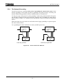
6 F 8 C 1 0 4 3
DeviceNet Module DN611/DN611A for
Integrated Controller V Series
model 2000 S2T
Instruction Manual
REQUIREMENTS
• Read this
operating.
instruction
manual
carefully
before
• Keep the manual aside to use when necessary.
• Pack the manual with the DN611/DN611A when
transferring or reselling.
August, 2002
© 2002 Toshiba Corporation
All rights reserved
6 F 8 C 1 0 4 3
© Copyright 2002 by Toshiba Corporation Tokyo, Japan
Toshiba Corporation reserves the right to make changes and improvements
to this publication and/or related products at any time without notice. No
obligation shall be incurred, except as noted in this publication.
This publication is copyrighted and contains proprietary material. No part of
this book may be reproduced, stored in a retrieval system, or transmitted in
any form or by any means — electrical, mechanical, by photocopying,
recording, or otherwise — without obtaining prior written permission from
Toshiba.
Important Information
Misuse of this equipment can result in property damage or human injury.
Because controlled system applications vary widely, you should satisfy
yourself as to the acceptabillity of this equipment for your intended purpose.
In no event will Toshiba Corporation be responsible or liable for either
indirect or consequential damage or injury that may result from the use of
this equipment.
No patent liability is assumed by Toshiba Corporation with respect to the
use of information, illustration, circuits equipment, of application examples in
this publication.
1
6 F 8 C 1 0 4 3
Safety Precautions
Thank you for purchasing Toshiba's DeviceNet module (DN611/DN611A) for Integrated
Controller V series model 2000 S2T. This instruction manual describes the handling, precautions
and operation of the DN611/DN611A.
Be sure to carefully read this manual and all of other related documents to learn the safety
precautions, notes, and knowledge about the DN611/DN611A before its installation, operation,
or inspection. This will allow you to operate your DN611/DN611A comfortably.
Important Information
1.
Toshiba's DN611/DN611A is designed and manufactured for use with general industrial
equipment(manufacture line control devices, machine tools, etc.); it is not intended for use
with equipment and systems which will endanger people's life during operation.
Contact the Toshiba dealer in advance when you are going to use your DN611/DN611A for
special applications such as transport vehicles(train, etc.), medical equipment, aerospace
equipment, nuclear power control equipment, underwater relay equipment, or other similar
applications.
2.
Toshiba's DN611/DN611A is manufactured under strict quality control. However, be sure
to install safety systems to minimize the effect of a possible accident before you apply your
DN611/DN611A to the equipment which will endanger people's life or cause serious
damage on the surroundings if the DN611/DN611A should break down.
3.
Toshiba's DN611/DN611A is meant for those who have general knowledge of handling
control equipment, especially the knowledge about installation, wiring, operation, and
maintenance of the DN611/DN611A. Incorrect handling of the DN611/DN611A can cause
electric shock, fire, failure, or/and malfunction. Therefore, don't engage in the installation,
wiring, operation, or maintenance of the DN611/DN611A if your knowledge including
electrical knowledge is not enough to handle control equipment. Instead, ask the qualified
person to do such work.
4.
This instruction manual and accompanying documents are meant for those who have
general knowledge about the programmable controller and how to handle control equipment.
If you have any questions on the content of this manual, don't hesitate to contact the
Toshiba dealer.
2
6 F 8 C 1 0 4 3
Safety Precautions (continued)
[Warning indication]
This instruction manual has the following important indications and symbols to prevent bodily
injury and property damage during operation. Be familiar with these safety indications to follow
during operation. After reading the text, keep the manual aside to consult when necessary.
Description of Safety Signs
Indication
Meaning
DANGER
Indicates misuse of the handling could cause a
fatal accident or serious injury.
CAUTION
Indicates misuse of the handling could cause
injury or material damage.
Injury means a hurt, burn, or electric shock, which requires neither hospitalization nor long-term
medical treatment by visits. Some of the CAUTION items, however, could bring about
grave consequences depending on the situation. So be sure to always follow the CAUTION
instructions.
3
6 F 8 C 1 0 4 3
Safety Precautions (continued)
• Precaution for operation
DANGER
1.
Configure an emergency-stop circuit, interlock circuit, and/or other similar safety circuits
outside the PC and DN611.
If the PC or DN611 gets failed or malfunctioned, it can cause an accident which will lead to
bodily injury and/or mechanical damage.
S2T User’s manual
CAUTION
2.
Secure the safe environment before executing program modification, forcible output, RUN,
or HALT instruction during operation. An operational mistake can cause mechanical
damage or accident.
S2T User’s manual
• DIP switch for setting the operating mode/communication rate
CAUTION
1.
2.
3.
4.
5.
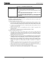
Set and keep "OSEN" on the DIP switch to OFF. Setting it to ON can get failed or
malfunctioned.
When you set "BUSOFF" on the DIP switch to OFF, transmission will restart
automatically even when busoff occurs. Unless the cause of the DN611's busoff (cause of
communication error) is solved, however, busoff may get repeated.
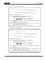
When you set both of communication rate DR0 and DR1 to ON and turn on the power of
the S2T, "Communication Rate Setting Failed" will appear with the following indications:
• The "MS" LED is blinking red.
• "F7" and the local station node address are being displayed alternately on the
7-segment LED.
To clear these indications, set DR0 and DR1 correctly and, issue a reset request or turn
OFF and ON the power.
Set the communication rates of your nodes being connected to the network, to the same
communication rate. Setting different communication rates on your different
nodes will cause slave devices or the DN611 to get malfunctioned,
resulting in no communication started.
Read the relevant manuals and descriptions to set the communication rate of your slave
devices.
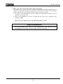
Don't change over the communication rates while your S2T is rising just after the turning on
power. In particular, never change the communication rate while communicating with slave
devices. Failing to do so will cause "Communication Rate Setting Failed" to appear.
To clear this indication, set the DIP switch to the correct setting and, issue a reset
request or turn OFF and ON the power.
3.2.1 DIP Switch for Setting the Operation Mode/Communication Rate
4
6 F 8 C 1 0 4 3
Safety Precautions (continued)
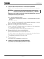
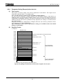
• Rotary switch for setting the node address
CAUTION
1.
When you set a value within 64 to 99 to the node address of your DN611 and turn ON the
power of your S2T, "Node Address Setting Failed" will appear with the following
indications:
• The "MS" LED is blinking red.
• "F6" and the local station node address are being displayed alternately on the
7-segment LED.
To clear these indications, set the correct value to the node address and, issue a reset
request or turn OFF and ON the power.
2.
If your DN611 node address has the same value with another node and when the DN611
comes into run state, "Node Address Duplicated" will appear with the following indications:
• The "MS" LED is lighting red and/or the "NS" LED is lighting red.
• "70" and the local station node address are being displayed alternately on the
7-segment LED.
To clear these indications, set the correct value to the node address and, issue a reset
request or turn OFF and ON the power.
3.2.2 Rotary Switch for Node Address Setting
• Mounting in the base unit
CAUTION
1.
Since the DN611 is designed for Toshiba's S2T, be sure to mount your DN611 in the base
unit, instead of using it in stand-alone; don't use it for other applications. Unauthorized
applications can cause electric shock, bodily injury, and/or mechanical malfunction.
2.
Be sure to turn OFF the power (on the S2T side and network side) before attaching or
detaching the DN611 and/or the terminal block. Failing to do so will cause electric shock,
malfunction, and/or failure.
3.
Keep the DN611 free from foreign matter such as electric-wire waste. Failing to do so
could cause fire, failure, and/or malfunction.
4.
Check the connectors, cables, and base unit of the DN611, for their firm connection and
mounting using stoppers and screws. Note loose connection or mounting can be shaky or
easily disconnected off, resulting in failure or malfunction of the DN611.
3.3 Mounting in the Base Unit
5
6 F 8 C 1 0 4 3
Safety Precautions (continued)
• Connection with the network
CAUTION
1.
Don't engage in attaching or detaching the DeviceNet cable with the network side
connector during network operation. Failing to do so can cause reverse connection or short
circuit of the network power, resulting in no communication with other nodes.
2.
When you connect the DeviceNet cable with the network side connector, be sure not to
make the wrong connection. Failing to do so can cause short circuit of the network power,
resulting in no communication with other nodes.
3.
Neither attach nor detach the network side connector with the device side connector on the
DN611 front panel while S2T is rising just after the power is turned ON. Failing to do so
can cause the DN611 to fail or malfunction.
4.
Attaching the opposite end of the network side connector with/from the device side
connector is not possible because of the specific form. Trying connecting the wrong end by
excessive force can damage both the network side connector and the device side
connector.
5.
Be sure not to wire the cable in too tightly stretched state or in bent state.
Also, don't put heavy stuff on the cable. Otherwise, the cable could break.
6.
Ask the qualified expert for the installation work of the DeviceNet cables because it
requires sufficient safety and noise-suppression measures. Refer to DeviceNet Volume I,
Release 1.3, for the standard installation.
3.4 Connection with the Network
6
6 F 8 C 1 0 4 3
Safety Precautions (continued)
• Turning ON/OFF the power of master/slave and the network
CAUTION
1.
Be sure to turn ON the network power before turning ON the power of the DeviceNet
devices.
Some nodes of the slave devices use the network power as the operation power while other
slave devices indicate an error when their work power is not supplied. Therefore, be sure to
switch ON the network power. Also note unless the network power is switched ON, your
DN611 cannot start communication with slave devices.
2.
Be sure the network power is supplied to all the nodes being connected with the network.
The node to which no network power is supplied could cause communication obstacle to
other nodes.
3.
Make sure the power of all slave devices is switched ON before the DN611 begins
communication. When the DN611 begins communication while the power of a slave device
is not switched ON, the DN611 will display an error message of no response from that
device.
4.
While network communications are operating, don’t shut OFF the network power. Failing
to do so will cause the entire network communications to stop and, one of the nodes
become busoff state.
5.
Switch OFF the S2T side power at last after the DN611 begins communications. This
helps the master device (DN611) to be recognized from the network and prevents slave
devices from malfunctioning.
3.5 The Network Power/Grounding
7
6 F 8 C 1 0 4 3
Safety Precautions (continued)
Relating to the following sections:
• How to handle your DN611 (software)
• Examples of DN611 applications
• RAS information
CAUTION
1.
Chapter 4 describes the subjects necessary for using diverse functions of the DN611 from
the S2T. Chapter 5 describes, based on the subjects explained in Chapter 4, setting the
DN611 parameters, activating transmission, inputting/outputting data with slave devices,
and the procedure for reading RAS information including event history, and sample
programs.
Write programs after understanding the contents. As sample programs are basic, you
need to examine your programs from beginning to end before applying them to actual
systems.
4. How to Handle Your DN611 (software)
5. Examples of DN611 Applications
6. RAS Information (except RAS area on communication memory)
• Allocation of slave device data to input/output data area
CAUTION
1.
When a slave device has odd transmission/reception bytes in size, the actual size plus
1 byte are allocated to the DN611 input/output area.
2.
When you add a new slave device, enter a new value larger than the node addresses of the
present slave devices. For Figure 4.8, enter a value larger than "41" for the node address of
a new slave. If the node address of a new slave device is set to "18", allocating data area of
node addresses 20/30/40 will be shifted.
3.
Don't change the input/output data size for slave devices (FLEX-I/O, etc.) which are flexible
in data allocation size. If changed, the slave devices with a node address larger than that of
the slave device changed data size will be shifted in their data allocation.
4.4 Allocating Slave Device Data to the Input/Output Data Area
• Operating mode of the S2T and the DN611
CAUTION
1.
If the S2T turns into HALT/ERROR mode, the DN611 in run mode becomes standby mode.
4.6.1 DN611 Operation Mode
5. Examples of DN611 Applications
8
6 F 8 C 1 0 4 3
Safety Precautions (continued)
• Action when your DN611 is reset
CAUTION
1.
Neither issue a request from the S2T to DN611 while the DN611 is being reset nor execute
data input/output. Otherwise, the instruction requested will be completed abnormal (error of
station mode abnormal), or the module self-check will fail turning into down mode.
[4.6.2 Reset Request]
• Setting slave device parameters
CAUTION
1.
The parameter setting request (slave device) sets the parameters of slave devices on to the
non-volatile memory in the DN611. As long as the slave devices configuration is
unchanged, you don’t need to execute this request every time when the power is switched
ON. In addition, when the parameters of the slave device requested and the parameters of
the slave device in the non-volatile memory are same, this setting request is not executed.
2.
When the slave devices configuration needs to be changed, delete the salve devices
parameters using a reset request before setting new slave devices parameters.
3.
The number of times available for setting slave devices parameters in the non-volatile
memory of the DN611 is 300 times.
4.
The DN611 has the following restriction for transmitting "0 byte" to a slave device from the
DN611.
• When a slave device comes into no communication state with the DN611 due to some
reason (for example, the power of the slave device is OFF; the connector is
disconnected, etc.), the DN611 cannot recognize the slave device is abnormal.
Even after the cause of the failed communications is solved, the DN611 and the slave
device cannot communicate with each other.
Note: The above restriction of the present DN611 will be solved by a version-up of the
internal software.
4.6.4 Parameter Setting Request (slave device)
• Installation environment and mounting in the base unit
CAUTION
1.
Apply the environment specified in the User’s Manual of the S2T.
When using your DN611 in the environment other than specified, the DN611 can cause
electric shock, fire, failure, and/or malfunction.
2.
Mount your DN611 in the way specified in the User’s Manual of the S2T.
If mounted in the direction other than specified or if mounted incorrectly, the DN611 could
fall off, or cause fire, failure, and/or malfunction.
8.1 Installation Environment and Mounting in the Base Unit
9
6 F 8 C 1 0 4 3
Safety Precautions (continued)
• Mounting/removing the module
CAUTION
1.
Since the DN611 is designed for the S2T, be sure to attach it to the base unit. Don't use
your DN611 in stand-alone state or to other applications.
Failing to do so could cause electric shock, injury, and/or failure.
2.
Be sure to turn OFF the power before mounting, removing, wiring, or un-wiring the DN611.
Failing to do so can cause electric shock, malfunction, and/or failure.
3.
Keep your DN611 free from foreign matter such as electric-wire waste. Failing to do so
could cause fire, failure, and/or malfunction.
4.
Check the connectors and cables and the DN611 mount in the base unit, for their firm
connections and mount using stoppers/screws. Loose connection and mounting becomes
shaky and disconnected, resulting in failure or malfunction.
8.2 Mounting/Removing the Module
• Wiring the power and grounding
CAUTION
1.
Be sure to turn OFF the power before wiring cables. Failing to do so could cause electric
shock.
2.
Use crimp-on connectors with sheath or cover the conducting part with tape when wiring
your S2T power module. Also, handle the terminal block cover correctly to avoid fall-off and
damage when fixing. Be sure to fix the cover on the terminal block when completing the
wiring. If the conducting part is exposed, you can have electric shock.
3.
Be sure to have grounding. When not grounded, electric shock and/or malfunction can
occur.
4.
Make sure the wiring is correct when connecting the DeviceNet cables to the network side
connector. The short circuit of the network power, etc. can fail communication with other
nodes.
5.
When you are going to detach or connect the network side connector to/from the device
side connector on the DN611 front panel, don't engage yourself while the S2T side power is
rising. Failing to do so can cause the DN611 to fail or malfunction.
6.
Attaching the opposite end of the network side connector with/from the device side
connector is not possible because of the specific form. Trying connecting the wrong end by
excessive force can damage both the network side connector and the device side
connector.
7.
Ask a qualified person to wire cables. Incorrect wiring can cause fire, failure, and/or electric
shock.
8.3 Power Unit Wiring/Grounding
10
6 F 8 C 1 0 4 3
Safety Precautions (continued)
• Basic caution in network Installation
CAUTION
1.
Ask the qualified subcontractor for sufficient safety and noise-suppression measures when
installing the DeviceNet cable.
Refer to DeviceNet Volume I, Release1.3, for the standard installation.
2.
It is recommended to consign a subcontractor specialized in safety measures and
standards.
3.
Avoid the network components of the DeviceNet cable from being installed in a noisy
environment. When installing, be sure to furnish noise-suppression measures as described
in the following section.
8.4 Network Installation
• Maintenance
CAUTION
1.
Be sure to turn OFF the power mounting or removing the module, terminal block, and
cable. Failing to do so can cause electric shock, malfunction, and/or failure.
2.
Carry out daily check, periodical check, and cleaning to keep the system in normal
condition.
3.
If your DN611 does not operate normally, refer to "7. Troubleshooting" to identify the cause
of the trouble.
Contact a Toshiba's branch office (or dealer) or service agency for returning your DN611 for
repair when failed. Operation and safety of your DN611 can be guaranteed only when
repaired by Toshiba or a Toshiba's authorized service agency.
4.
Neither try to disassemble nor modify the hardware of the module. Similarly, don't modify
the software by any means. Failing to do so could cause fire, electric shock, and/or injury
due to failure or malfunctioning.
5.
Make sure you are safe when measuring the voltage on the connector of the module.
Failing to do so could cause electric shock.
6.
Stop the network and turn OFF the S2T side power before replacing the module.
Failing to do so could cause electric shock, malfunction, and/or failure.
7.
Don't use your DN611 in abnormal condition such as smoking or nasty smelling.
Failing to do so could cause fire, electric shock, and/or failure.
If such an abnormal condition happens, turn OFF all the power supplies immediately and
contact a Toshiba branch office (or dealer) or authorized service agency.
Since it is very dangerous, don't engage yourself in modifying or repairing your DN611 by
any means.
Appendix (maintenance)
11
6 F 8 C 1 0 4 3
Usage Recommendations
This section puts together the knowledge and handling manners necessary for correct operation.
Read the section carefully and be familiar with equipment knowledge, safety information, and
notes.
• Network cnfiguration
Usage Recommendation
1.
Don't make a network configuration whose extended trunk line and drop lines have no node
being connected.
2.
Don't attach a terminal resistor to the node. It could cause communication error.
3.
Attach a terminal resistor to both ends of the trunk line; don't attach a terminal resistor on
the end of a drop line. Attach only to both ends of the trunk line.
1.2 Network Configuration of the DeviceNet
•
Switch setting
Usage Recommendation
1.
Use a small minus screwdriver for changing the value of the DIP switch.
3.2.1 DIP Switch for Setting the Operation Mode/Communication Rate
Usage Recommendation
1.
Use a small minus screwdriver for changing values of the rotary switch.
3.2.2 Rotary Switch for Node Address Setting
• Connecting your DN611 with the network side connector
Usage Recommendation
1.
Loosen the cable fixing screws on the connector before inserting a cable into the network
side connector. The cable cannot be fixed when the screws are kept tightened.
2.
Colors corresponding to cable colors are printed by the device side connector of the
DN611. Match the cable colors with the printed colors to have correct wiring.
3.
The DN611 and the DN311 (DeviceNet module for T3/T3H) have different directions for
attaching the network side connector.
4.
DeviceNet cable, power tap, and device tap (connecting the trunk line with drop lines) are
necessary when constructing a system using a DeviceNet. Refer to "3.6 The Network
Components" for detail.
Some of the network components must be prepared by the user.
5.
When you use the network side connector that has the upper and lower rows with holes for
cables (at the left-side Figure 3.5), the connector protrudes from the left-side DN611 about
5mm. When you attach or detach the left-side module of DN611, you must detach the
connector from DN611.
3.4.2 Connecting Network Side Connector to the DN611
12
6 F 8 C 1 0 4 3
Usage Recommendations (continued)
• Network power configuration
Usage Recommendation
1.
Consider not only current capacity of the trunk line but also current capacity of drop lines
when you install a node on a drop line.
2.
In particular, when you are connecting nodes in daisy chain on a drop line, be careful not
to have insufficient current capacity.
3.
Use a network power whose capacity is much larger than the total current consumption
necessary for the network.
3.5.2 How to Configure Network Power Units
• Network power unit
Usage Recommendation
1.
Use a network power whose capacity is much larger than the total current consumption
necessary for the network.
3.5.3 The Network Power Unit(24Vdc)
• Registering your DN611 module
Usage Recommendation
1.
When your DN611 is going to be I/O registered in the S2T, leave blank for the slot where
the DN611 is installed.
After automatic allocation is performed, the DN611-installed slot is left blank.
4. How to Handle Your DN611 (software)
• Node address of your DN611
Usage Recommendation
1.
Set the node address of your DN611 to a value smaller than the node addresses of slave
devices(because of the feature of CAN currently used in the DeviceNet).
4.6.3 Parameter Setting Request (local node)
• How to solve overrun errors
Usage Recommendation
1.
Reduce the network communication speed when an overrun error occurs (500 kbps -> 250
kbps -> 125 kbps).
7. Troubleshooting (Data Communication with Slave Devices)
13
6 F 8 C 1 0 4 3
About This Manual
Thank you for purchasing Toshiba's Integrated Controller V series model 2000 S2T.
This manual describes the specification, handing manners, and sample programs of the
DeviceNet module (called as the "DN611/DN611A") used for S2T. Read this manual to handle
and operate your DN611/DN611A correctly.
This manual consists of the following chapters:
Chapter 1: Overview of the DeviceNet Module
Outlines functions of the DN611/DN611A, specification, and application systems, etc. Read this
chapter to know basic performances of the DN611/DN611A.
Chapter 2: Names and Functions of DN611/DN611A Parts
Describes the names and functions of DN611/DN611A parts. Read this chapter carefully since
important information, required for hardware settings in the next chapter, is included in this
chapter.
Chapter 3: Preparation for Operation (hardware)
Describes the hardware preparation and setting necessary for your DN611/DN611A operation.
Chapter 4: How to Handle Your DN611 (software)
Explains accessing the DN611/DN611A from the S2T and software settings.
Chapter 5: Examples of DN611 Applications
Describes sample programs of handling the DN611/DN611A explained in Chapter 4.
Chapter 6: RAS Information (except RAS area on communication memory)
Describes the formats and contents of RAS information on the DN611/DN611A (except for
RAS area on communication memory).
Chapter 7: Troubleshooting
Explains possible causes and solutions when your DN611/DN611A malfunctions.
Chapter 8: Installation/Wiring Work
Explains how to install your DN611/DN611A and S2T, how to wire transmission cables, and
how to arrange other preparation work.
Appendix
Describes the maintenance and check items, the execution time of READ/WRITE instructions
of the S2T and the distinction between DN611 and DN611A.
14
6 F 8 C 1 0 4 3
In addition to this instruction manual, the S2T instruction manuals are also prepared for your
reading.
Registered Trademarks:
n DeviceNet is a registered trademark of ODVA (Open DeviceNet Vendor Association).
n PowerTap, T-Port Tap, DeviceBox Tap, and FLEX I/0 are registered trademarks of
RockWell Automation Co., Ltd.
n COMBICON is a registered trademark of Phoenix Contact Corporation.
15
6 F 8 C 1 0 4 3
Contents
1. Overview of The DeviceNet Module ..................................................................19
1.1 Features and System Configuration Examples of the DeviceNet Module
(DN611) ........................................................................................................ 19
1.2 Network Configuration of DeviceNet .......................................................... 21
1.2.1 The Network Configuration.............................................................................21
1.2.2 Trunk Line/Drop Line and Maximum Cable Length ...........................................22
1.2.3 The Terminal Resistor ...................................................................................24
1.3 Conformity Specification and Trademarks.................................................. 25
1.4 The Basic Functions ...................................................................................... 26
1.4.1 The Polling Instruction/Response Mode ..........................................................26
1.4.2 The Bit Strobe Instruction/Response Mode .....................................................27
1.4.3 Synchronization/Asynchronous Mode and Data Update Cycle ..........................28
1.5 The DN611 Specification ............................................................................... 30
1.5.1 The Function Specification ............................................................................30
1.5.2 Number of Mounting Modules ........................................................................31
2. Names and Functions of DN611 Parts .............................................................33
2.1 Outer Dimensions and Sizes ........................................................................ 33
2.2 Names of DN611 Parts ................................................................................... 34
2.3 Functions of DN611 Parts ............................................................................. 36
3. Preparation for Operation (hardware)...............................................................38
3.1 DN611 Setting Flowchart (hardware)........................................................... 38
3.2 Switch Setting ................................................................................................ 39
3.2.1 DIP Switch for Setting the Operation Mode/Communication Rate......................39
3.2.2 Rotary Switch for Node Address Setting .........................................................41
3.3 Mounting in the Base Unit ............................................................................ 42
3.4 Connection with the Network....................................................................... 43
3.4.1 Connecting DeviceNet Cables to Network Side Connectors ..............................44
3.4.2 Connecting the Network Side Connector to the DN611.....................................45
3.5 The Network Power/Grounding.................................................................... 47
3.5.1 The Network Power Mechanism.....................................................................47
3.5.2 How to Configure Network Power Units...........................................................48
3.5.3 The Network Power Unit (24 Vdc)...................................................................54
3.5.4 The Network Grounding.................................................................................55
3.5.5 Procedure for Switching-ON/Shutting-OFF the Power.......................................56
3.6 The Network Components .......................................................................... 57
4. How to Handle Your DN611 (software).............................................................60
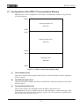
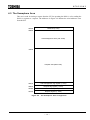
4.1 Configuration of the DN611 Communicatio n Memory ............................... 61
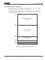
4.2 The Input/Output Data Area .......................................................................... 62
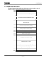
4.3 The RAS Information Area............................................................................. 66
16
6 F 8 C 1 0 4 3
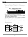
4.4 Allocating Slave Device Data to the Input/Output Data Area ................... 75
4.5 The Semaphore Area..................................................................................... 76
4.6 Requests to the DN611 ................................................................................. 79
4.6.1 The DN611 Operation Modes .........................................................................80
4.6.2 Reset Request .............................................................................................81
4.6.3 Parameter Setting Request (local node)..........................................................82
4.6.4 Parameter Setting Request (slave device) .......................................................85
4.6.5 Operation Mode Control Request ...................................................................88
4.6.6 RAS Information Read Request......................................................................89
4.6.7 Time Setting Request ...................................................................................90
4.7 Completion Status ......................................................................................... 91
5. Example of DN611 Applications.........................................................................92
5.1 The DN611 Operation Order ......................................................................... 92
5.2 Module Setting Procedure ........................................................................... 93
5.2.1 Accessing the DN611 in Module Setting.........................................................94
5.2.2 Configuration of a Module Setting Sample Program..........................................96
5.2.3 Reset Request .............................................................................................97
5.2.4 Parameter Setting Request (local node)..........................................................99
5.2.5 Parameter Setting Request (slave device) ..................................................... 100
5.2.6 Operation Mode Control Request ................................................................. 106
5.2.7 RAS Information Read................................................................................. 111
5.2.8 Time Setting Request ................................................................................. 114
5.3 Slave Data Input/Output .............................................................................. 116
5.3.1 Slave Device Check .................................................................................... 116
5.3.2 Asynchronous Mode Data Input/Output ........................................................ 117
5.3.3 Synchronous Mode Data Input/Output .......................................................... 122
6. RAS Information (except RAS area on communication memory) .......... 129
6.1 Module Status / Network Status LED (MS/NS) .......................................... 130
6.2 Indications of the 7-Segment LED ............................................................. 131
6.3 RAS Information Reading Data ................................................................... 133
6.3.1 The RAS Counter ....................................................................................... 133
6.3.2 Event History ............................................................................................. 136
6.3.3 Execution Node Information......................................................................... 139
7. Troubleshooting.................................................................................................. 141
7.1 When Starting up the Module .................................................................... 141
7.2 Reset Request (scan list clear).................................................................. 142
7.3 When the Module Doesn't Become Run Mode ........................................ 143
7.4 Data Communication with Slave Devices ................................................. 146
17
6 F 8 C 1 0 4 3
8. Installation/Wiring Work..................................................................................... 148
8.1 Installation Environment and Mounting in the Base Unit....................... 148
8.2 Mounting/Removing the Module ............................................................... 148
8.3 Power Unit Wiring/Grounding .................................................................... 149
8.3.1 Power Unit Wiring....................................................................................... 149
8.3.2 Grounding.................................................................................................. 149
8.4 Network Installation..................................................................................... 150
8.4.1 Installation Gists Outside the Board ............................................................. 150
8.4.2 Installation Gists Inside the Board................................................................ 153
Appendix
Appendix
Appendix
Appendix
Appendix
1
2
3
4
Maintenance and Inspection............................................................ 154
READ/WRITE Instruction Execution Time ........................................ 156
DN611A..……….……………………………………………………… ...... .157
Added/ corrected function of DN611A firmware (rev. B)……..…..…. .... 161
18
6 F 8 C 1 0 4 3
1. Overview of the DeviceNet Module
1.1
Features and System Configuration Examples of the DeviceNet Module (DN611)
This section describes the features and system configuration examples of the DeviceNet module
(DN611/DN611A) for the Integrated Controller V series model 2000 S2T. The
DN611/DN611A is an interface module for connecting the DeviceNet, which is a device level
network for FA, to the S2T.
Hereafter, the Integrated Controller model 2000 S2T is respectively called the "S2T". Likewise,
the DeviceNet module for the Integrated Controller model 2000 series is also called the
"DN611." The differences between DN611 and DN611A are in appendix 3.
(1)
Conformed with DeviceNet
DeviceNet is a standardized device level network for factory automation(FA), developed by
RockWell Automation Co. in USA. A nonprofit organization, called ODVA (Open DeviceNet
Vendor Association), is serving as the center for the maintenance/extension of the DeviceNet
specification and for conformable products introduction.
The DN611, functioning as the master (parent station) device on a DeviceNet, performs data
input/output between the master device and the DeviceNet slave (child station) devices, which
are developed by different makers (vendors) in and outside Japan and conform with the
DeviceNet, to interface such slave devices with the S2T .
(2)
Input/Output Data Size, Number of Slave Devices, communication Rate and
Network Length
A DN611 allows a DeviceNet to have one network to be connected. The sizes of inputting and
outputting data, allowed between a DN611 and slave devices are 128 words for input and 128
words for output (one word = 16 points).
Input data and output data, so far as each of them is within 128 words in total, can be exchanged
data with up to 63 slave devices. (Since the amount of data outputted to a slave device and the
amount of data inputted from a slave device vary depending on the slave device, check the slave
device specification of data size).
The definition of input data and output data, dealt in this book, is shown in the following figures.
Output data :
S2T
→
DN611
→
Slave device
Input data
S2T
←
DN611
←
Slave device
:
Figure 1.1
Definition of Output Data and Input Data
Three types of communication rates, namely 500 kbps, 250 kbps and 125 kbps are available.
The maximum network length varies depending on the communication rate (l00 m for 500 kbps,
250 m for 250 kbps, and 500 m for 125 kbps).
The detail is explained in "1.2 Network Configuration of DeviceNet."
19
6 F 8 C 1 0 4 3
(3) Means of Inputting/Outputting Data
The DN611 supports "polling instruction/response" and "bit strobe instruction/response," both of
which are specified in the DeviceNet specification as the means of inputting/outputting data
to/from slave devices. The details of "polling instruction/response" and " bit strobe
instruction/response" are explained in "1.4 The Basic Functions."
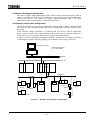
(4) Examples of the System Configuration
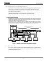
This section describes a typical system configuration using the DN611, which is mounted on the
I/O slot of the S2T. The DN611 allows the S2T to exchange data with slave devices on the
DeviceNet.
In the following example, the DN611 is connected with slave devices, such as input/output
devices, sensor, and drive unit, which conforms with the DeviceNet specification. Moreover, a
control LAN (FL-net) is used to connect the S2T with a higher-rank controller.
A number of wiring combinations meeting the installation environment are available because the
T branch topology and the multi-drop topology are combinable when wiring a DeviceNet.
High-rank computer
EN: Ethernet module
FL: FL-net module
Ethernet
FL -net
S
2
T
F
L
S
2
T
E
N
F
L
D
N
6
D
N
6
DeviceNet
DeviceNet
Input/Output
device
Input/Output
device
Sensor
Sensor
Drive unit
Drive unit
Input/Output device
Sensor
Figure 1.2
Example of the System Configuration
20
Input/Output
device
6 F 8 C 1 0 4 3
1.2 Network Configuration of DeviceNet
This section describes the network configuration of the DeviceNet.
1.2.1
The Network Configuration
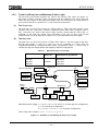
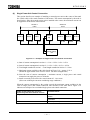
The network configuration of a DeviceNet consists of a trunk line and drop lines as shown in
Figure 1.3.
(1)
The Nodes
The nodes of the DeviceNet in Figure 1.3 have slave devices such as input/output devices,
sensors, and drive units, and a master device such as the DN611, to exchange data with each
other. One network can have up to 64 nodes and one master device. Physical arrangement of a
master device and slave devices has no particular restrictions.
Each of the DeviceNet devices on a network has a unique number (NA: node address) to
identify the node from the other nodes. The node address values must be within 0 to 63 in
decimal scale, and the node addresses in the network must be different from the others.
(2)
The Trunk Line
According to the DeviceNet specification, a trunk line is a cable which connects nodes located
most distant. The trunk line can have nodes directly-connected with it (connection with no drop
line). The length of the trunk line varies depending on the communication rate of the network.
The both ends of the trunk line need a terminal resistor.
(3)
The Drop Line
All the cables branched from taps on the trunk line fall on drop lines. The drop line has a
maximum length of 6 meters (from tap to most distant node) regardless of the communication
rate on the network (The total extension of drop lines varies depending on the communication
rate on the network). A drop line can have one or more nodes connected. The following three
types of node configurations are available, as shown in Figure 1.3.
a) Configuration of drop lines short from the tap/multiport tap
b) Configuration of multidrops on a drop line
c) Configuration of branches on a drop line (no branch configuration for the trunk line)
Branch configuration
Multiport tap
Node 45
Node 35
Node 50
Tap
Node 30
Node 55
Node 40
Terminal
resistor
Terminal
resistor
Tap
Node 60
Tap
Multiport tap
Multidrop
configuration
Node 0
No drop line
Node 5
Node
10
Node
15
Node
20
Node
25
Short drop line configuration
Figure 1.3
Example of DeviceNet Network Configuration
21
Trunk line
Drop line
6 F 8 C 1 0 4 3
1.2.2
Trunk Line/Drop Line and Maximum Cable Length
The DeviceNet specification stipulates the Thick Cable and the Thin Cable. For detail, see
DeviceNet Volume I. Currently, cables conforming with the standards of the Thick Cable and
Thin Cable are available in the commercial market. Buy ones which meet the configuration of
your network (Details are explained in "3.6 The Network Components").
(1)
The Trunk Line
The trunk line of a DeviceNet consists of a Thick Cable or a Thin Cable (their mixture is also
possible). Since the Thin Cable is flexible compared with the Thick Cable, wiring the cable is
easy. Conversely, the Thick Cable allows longer network cabling than the Thin Cable. A
maximum of the trunk line length varies depending on the type of cable used and the
communication rate on the network. For details, see "3 The Maximum Network Length."
(2)
The Drop Line
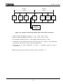
The drop lines of a DeviceNet consists of Thin Cables. Table 1.1 lists the length of drop lines
and the total length. A node on a drop line can be configured in a short drop line
configuration/multi-drops configuration/short brunch configuration. Figure 1.4 shows how to
calculate the drop line length and the total length by different configurations.
Table 1.1
Communication Rate
Maximum Drop Line Length
Drop Line
Total Extension by Network
125 kbps
156 meters
250 kbps
6 meters
78 meters
500 kbps
39 meters
Branch configuration
Multiport tap
Node 45
Tap
Terminal
resistor
g
Node 35
f
i
Node 50
Tap
h
e
Node 30
Node 55
Node 40
Node 60
Terminal
resistor
Tap
Multiport tap
Multidrop
configuration
a
Node 0
Node 5
Node
10
b
Node
15
c
Node
20
d
Node
25
Short drop line configuration
Individual drop line length: a ≤ 6 m, b ≤ 6 m, c ≤ 6 m, and d ≤ 6 m (short drop line configuration)
e ≤ 6 m (multi-drops configuration)
f + g ≤ 6 m, f + h ≤ 6 m, f + i ≤ 6 m (branch configuration)
Total of drop lines extended : a + b + c + d + e + f + g + h + i
Figure 1.4
Example of Calculating the Drop Line Length
22
6 F 8 C 1 0 4 3
(3)
The Maximum Cable Length
The distance between two nodes on the network cannot exceed the "Maximum cable length"
specified in the DeviceNet specification. In Figure 1.4, the distance from node 0 to node 60 is
not allowed to exceed the "Maximum cable length."
The "Maximum cable length" varies depending on the communication rate of the
network and the type of the cable used for the trunk line .
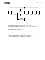
a) Table 1.2 lists the maximum cable length for the case that the trunk line consists of a Thick
Cable alone and no drop line is connected on it (that is, all nodes are connected on the trunk
line), as shown in Figure 1.5. In this case, "maximum trunk line length between node 0 and
node n" = "maximum cable length."
Moreover, when the "maximum trunk line length between node 0 and node n" = "maximum
cable length," no new node can be attached outside node 0 and node n..
Distance between two nodes ≤ Maximum cable length
Terminal
resisto r
Node 0
Figure 1.5
Node 2
•
Node 3
•
• •
•
• •
•
•
Terminal
resisto r
Node n
Distance Between Two Nodes on a Network With No Drop Line
Table 1.2
Maximum Cable Length (Thick Cable/Thin Cable alone)
Communication Rate
Thick Cable alone
Thin Cable alone
125 kbps
500 m
100 m
250 kbps
250 m
100 m
500 kbps
100 m
100 m
b) Figure 1.6 shows the maximum distance between two nodes in the case that a Thick
Cable or Thin Cable alone is used for the trunk line and that drop lines are used.
Table 1.2. lists the maximum cable length. In this case, the "maximum trunk line length
between two nodes" is as follows:
Maximum trunk line length between two nodes
= Maximum cable length(value in Table 1.2)
− Total length of drop lines for both ends nodes of trunk line
For Figure 1.6, the maximum trunk line length between node 0 and node n is equal to the
maximum cable length (value in Table 1.2) minus total length of drop lines for node 0 and
node n.
Terminal
resisto r
Distance between two nodes ≤ Maximum cable length
Node 2
Node 3
Node 0
Figure 1.6
•
•
• •
•
• •
•
Terminal
resisto r
•
Node n
Distance Between Two Nodes on a Network with Drop Lines
23
6 F 8 C 1 0 4 3
c) Figure 1.7 shows the maximum distance between two nodes in the case that the trunk
line consists of Thick Cable and Thin Cables and that drop lines are connected. Use the
formulas in Table 1.3. for calcula ting the maximum cable length.
In this case, the "maximum trunk line length between two nodes" is represented in the
following formula:
Maximum trunk line length between two nodes
= Maximum cable length (value in Table 1.3)
− Total length of drop lines for the nodes at
both ends of trunk line
For Figure 1.7, the maximum trunk line length between node 0 and node n is equal to the
maximum cable length (value in Table 1.3) minus the total length of the drop lines for node 0
and node n.
Distance between two nodes ≤ Maximum cable length
Terminal
resistor
Terminal
resisto r
L-thin
•
Node 0
• • •
• • •
• •
Node 3
• •
• • •
• •
• •
Node n
Figure 1.7
Distance Between Two Nodes on a Network with Drop Lines
Table 1.3
Maximum Cable Length (Mixture of Thick Cable/Thin Cable)
Communication Rate
Calculation Formula
125 kbps
L-thick + 5 × L-thin ≤ 500 m
250 kbps
L-thick + 2.5 × L-thin ≤ 250 m
500 kbps
L-thick + L-thin ≤ 100 m
L-thin:
L-thick:
1.2.3
L-thick
Length of trunk line using thin cable (m)
Length of trunk line using thick cable (m)
The Terminal Resistor
The DeviceNet needs a terminal resistor on both ends of the trunk line in order to reduce signal
reflections and stabilize communications. The specifications of the terminal resistor are as
follows:
• 121Ω
• 1% of the metal film
• 1/4 W
Terminal resistors conforming with the above specifications are available in the commercial
market. See "3 .6 The Network Components."
Usage Recommendation
1.
Don't make a network configuration whose extended trunk line and drop lines have no node
being connected.
2.
3.
Don't attach a terminal resistor to the node. It could cause communication error.
Attach a terminal resistor to both ends of the trunk line; don't attach a terminal resistor on
the end of a drop line. Attach only to both ends of the trunk line.
24
6 F 8 C 1 0 4 3
1.3 Conformity Specification and Trademarks
DeviceNet is a standardized device level network for factory automation (FA), which is
developed by RockWell Automation Co., Ltd. in USA. Currently, a nonprofit organization called
ODVA (Open DeviceNet Vendor Association) is serving as the center for the maintenance and
extensions of DeviceNet and introduction of conformable products.
The DeviceNet specification has Volume I: DeviceNet Communication Model and Protocol, and
Volume II: DeviceNet Device Profiles and Object Library, in which the hardware and software
specifications are defined.
The DeviceNet specification that the DN611 conforms with is found in Volume I, Release 1.3,
and Volume II, Release 1.2.
Trademarks:
n DeviceNet is a registered trademark of ODVA (Open DeviceNet Vendor Association).
n PowerTap, T-Port Tap, DeviceBox Tap, and FLEX I/0 are registered trademarks of
RockWell Automation Co., Ltd.
n COMBICON is a registered trademark of Phoenix Contact Corporation.
25
6 F 8 C 1 0 4 3
1.4 The Basic Functions
This section describes the following two functions for communicating between the DN611 and
slave devices.
1) Polling instruction/response mode
2) Bit strobe instruction/response mode
1.4.1
The Polling Instruction/Response Mode
The polling instruction/response mode is used for exchanging an arbitrary size of data between
the master device ⇔ slave devices. The master device has information on slaves devices (items
of scan list, such as node address, input/output data volume, etc.) on the network.
For polling instructions, based on such information, the master device outputs an arbitrary size of
data to slave devices. Slave devices transmit response data (arbitrary data size) to a polling
instruction to the master device (polling response).
It depends on the specification of a slave device how the slave device interprets the polling
instruction and what data the slave device transmits as the polling response. For this
communication function, it is prerequisite that the slave device supports the polling
instruction/response mode. (Almost all the slave devices on the DeviceNet support this
communication system).
(1)
The Polling Instruction
The example in Figure 1.8 indicates the DN611 is polling sensors, inputting sensor input
information, and trying to send output control data to the actuator. How to write polling output
data to the DN611 from the S2T is found in "5. Communication with Slave Devices."
S2T
Master
DN611
NA = 1
Slave 1
Proximity sensor
NA = 19
NA (Node Address):
Node identification number that individual DeviceNet
devices have in the DeviceNet network. The values
range from 0 to 63 in decimal scale.
In the DeviceNet network, the node addresses of the
devices must be unique and different from each other.
Slave 3
NA = 22
Polling instruction /
Figure 1.8
(2)
Slave 5
Actuator
NA = 52
Optoelectronic sensor
Polling response
Example of Polling Instruction/Response Mode
The Polling Response
A slave device which received a polling instruction transmits an arbitrary size of response data to
the master device. The content of response data varies depending on the specification of the
slave device. The mechanism the S2T reads polling response data from the DN611 is explained
in"5. Communication with Slave Devices."
26
6 F 8 C 1 0 4 3
1.4.2
The Bit Strobe Instruction/Response Mode
The bit strobe instruction/response mode is used for exchanging a small size of data between the
master device ⇔ slave devices. In the bit strobe instruction, based on the information obtained
from the scan list, the master device broadcasts 1-bit output data to individual slave devices.
These individual devices transmit data (0-8 bytes) in response to the bit strobe instruction to the
master device (bit strobe response).
It depends on the specification of a slave device how the salve device interprets a bit strobe
instruction and what data the slave device transmits to the bit strobe response.
For this communication function, it is prerequisite that the slave device supports the bit strobe
instruction/response mode.
(1) The Bit Strobe Instruction
Broadcasts data to bit strobe instruction/response mode supporting slave devices on the network.
The bit strobe instruction contains 64-bit output data, and each of the 64 bits is assigned to
individual node addresses on the network (Figure 1. 9).
The example in Figure 1.9 indicates the DN611 is inputting sensor information by the bit strobe
mode and trying to send output control data to the actuator. The way of writing output data in bit
strobe from the S2T to the DN611 is explained in "5. Communication with Salve Devices."
S2T
Master
DN611
NA = 1
Bit strobe instruction data
Bit number
0
Slave 1
Proximity sensor
NA = 19
1
Slave 2
Proximity sensor
NA = 21
•• • •
19
20
Slave 3
Photoelectric
sensor
NA = 22
Bit strobe instruction /
Figure 1.9
(2)
21 22
23 24
Slave 4
Photoelectric
sensor
NA = 23
•• • •
51
52
•• • •
63
Slave 5
Actuator
NA = 52
Bit strobe response
Example of the Bit Strobe Instruction/Response Mode
The Bit Strobe Response
A slave device which received the bit strobe instruction transmits 0 to 8 byte response data to
the master device. The contents of response data varies depending on the specification of the
slave device. The way the S2T reads bit-strobe response data from the DN611 is described in "5.
Communication with Slave Devices."
27
6 F 8 C 1 0 4 3
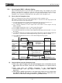
1.4.3
Synchronization/Asynchronous Mode and Data Update Cycle
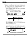
As explained in the preceding section, the communication function between the DN611 and
slave devices has the polling instruction/response mode and the bit strobe instruction/response
mode. Data can be exchanged between the S2T and the DN611 in synchronous mode or
asynchronous mode. This section describes the synchronous mode/asynchronous mode.
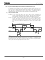
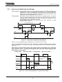
(1)
The synchronous mode
At output: The S2T writes output data to slave devices into the DN611 beforehand, and
activates a polling instruction/bit strobe instruction. When the polling instruction/bit
strobe instruction is activated, the DN611 sends the output data to slave devices.
At input:
The DN611 receives data from slave devices by a polling response/bit strobe
response. After having received data from all slave devices, the DN611 arranges
input data before notifying the input completion to the S2T. If the S2T is reading input
data, it will check for the input completion by the DN611 before reading the input
data.
S2T Data Update Cycle
S2T
Output
data
Input
data
Output
instruction
Output
data
Output
instruction
Input
completion
DN611
Slave
Output
processing
Iutput
processing
Response
Input
completion
Output
processing
Intput
processing
Response
Output data and input data exchanged between the S2T ⇔ the DN611 are synchronizing with
the output/input cycles of the S2T side program. For this reason, the size of synchronous data
value is equal to one-time output/input data to all slave devices.
28
6 F 8 C 1 0 4 3
(2)
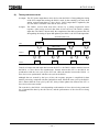
The asynchronous mode
At output: The S2T writes output data to slave devices into the DN611. Disregarding the timing
of the S2T's output data writing, the DN611 sends, by the scanning cycle at the local
station, written output data to a slave device. Unless output data is updated by the
S2T, the DN611 sends the same data to slave devices.
At input:
The DN611 receives data from slave devices by a polling response/bit strobe
response. After having received data from all slave devices, the DN611 updates
input data. The DN611 doesn't notify the completion of the data reception to the S2T.
Disregarding the timing of input data update by the DN611, the S2T reads input data.
S2T Data Update Cycle
Output
data
S2T
Output
data
Input
data
DN211 scan
DN611
Slave
Output
processing
Iutput
processing
Response
Output
processing
Intput
processing
Response
Outpu
processing
Intput
processin g
Outpu
processing
Response
Transfer of output data and input data between the S2T ⇔ the DN611 and the transfer between
the DN611 ⇔ slave devices are asynchronous. Transfer between the S2T ⇔ the DN611 are
synchronizes with the scan cycle by the S2T side, while the transfer between the DN611 ⇔
slave devices are synchronizes with the scan cycle in the DN611.
Although data are secured by the byte (8 bits), the sequence program is simplified for data
transfer processing, compared with the synchronous mode. When the scan cycle by the DN611
side is shorter than the scan cycle by the S2T, delay of data update time between the S2T ⇔
slave devices becomes smaller.
The scan time by the DN611 varies depending on the number of slave devices being connected,
size of transmission data by the slave device, and the performances of the slave device being
connected.
29
6 F 8 C 1 0 4 3
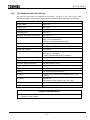
1.5 The DN611 Specification
1.5.1
The Function Specification
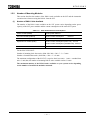
Table 1.4 lists the function specification of the DN611. The general specification of the DN611
conforms with the S2T main unit.
Table 1.4
Function Specification
Item
Specification
Module form (pet name)
DN611
Transmission specification
Conformed with the DeviceNet
Media access system
CSMA/NBA system (note)
Modulation
Baseband
Transmission path
Bus topology
Data rate
Max. network length
125 kbps
250 kbps
500 kbps
500 m
250 m
100 m
Max. number of nodes
64 units/network (1 master device, 63 slave devices)
Connector
MSTBP 2.5/5-STF-5.08 AB GY AU SO
TMSTBP 2.5/5-STF-5.08 AB GY AU
Phoenix Contact Corporation
Connection cable
DeviceNet THICK cable (thick cable)
DeviceNet THIN cable (thin cable)
Communication function
1. Polling instruction/response mode
(synchronous/asynchronous)
2. Bit strobe instruction/response mode
(synchronous/asynchronous)
RAS function
1. Self-check when the power is ON
ROM, RAM, and CAN controllers
DN611 communication memory for S2T
2. RAS information on the S2T interface buffer memory
3. Information by reading RAS information
• Event trace
• CAN controller (circuit) information
4. Time setting function
5. Displaying the module status/network status on the
7-segment LED on the front panel
Current consumption [mA]
S2T side (DC5V): 500 mA
Network side (DC 24 V): 90 mA
Outer dimensions [mm]
32.5 (W) × 138 (H) × 102.1 (D)
Weight [g]
200
Board specification
One slot (slot width)
Mounting
S2T base unit (basic/extension)
I/O slot
Number of modules
See "1.5.2 Number of Mounting Modules."
Access
READ/WRITE instruction (module control, data input/output)
Note: CSMA/NBA : Carrier Sense Multiple Access with Non-destructive Bitwise Arbitration
30
6 F 8 C 1 0 4 3
1.5.2
Number of Mounting Modules
This section describes the number of the DN611 units available on the S2T and the instruction
execution time when accessing the DN611 from the S2T.
(1)
Number of DN611 Units Available
The number of the DN611 units available on the S2T system varies depending on the power
capacity of the S2T power module and the current consumption of the entire S2T system.
Table 1.5
5Vdc Power/Current consumption
Power module (PS692)
5 Vdc power 5000 mA
S2T CPU module (PU672T)
5 Vdc current consumption
1200 mA
S2T CPU module (PU662T)
5 Vdc current consumption
1200 mA
Expansion I/F module (IF661)
5 Vdc current consumption (basic unit) : 150 mA
5 Vdc current consumption (extended unit) : 500 mA
DN611
5 Vdc current consumption
500 mA
For the PU672T/PU662T:
Number of mounting basic base units: (5000-150-1200) ÷ 500 = 7.3 → 7 units
Number of extended base units: (5000-500) ÷ 500 = 9 → 8 units
The maximum configuration of the PU672T is equal to basic base unit × 1 unit + extended base
unit × 3 unit; thus, the number of mounting DN611 units available reaches 31 units.
The maximum number of the DN611 units available on your system varies depending
on the number of non-DN611 modules mounted.
31
6 F 8 C 1 0 4 3
(2)
Instruction execution time when accessing the DN611 from the S2T
When outputting data to slave devices from the S2T through the DN611, the WRITE instruction
writes the output data in the DN611 from the S2T. When inputting data from slave devices
through the DN611, the READ instruction reads from the DN611.
Table 1.6 lists the instruction execution times of the S2T.
The DN611 has 128 words for the output data area (area where output data to slave devices are
stored) and 128 words for the input data area (area where input data from slave devices are
stored).
Table 1.7 lists the execution times for the WRITE/READ instructions by the S2T when
accessing 128 words. When input/output data with slave devices is smaller than 128 words, the
instruction execution time becomes shorter.
Conversely, when accessing the output data area/input data area several times, the sum of
instruction execution times increases depending on the number of accessed times (the output
data area/input data area is explained in "4.2 The Input/Output Data Area.")
Table 1.6
READ/WRITE Instruction Execution Time (μs)
READ instruction
WRITE instruction
Basic base unit
Extended base unit
123.8 + 5.00 × N
127.8 + 5.00 × N
127.8 + 5.38 × N
127.8 + 5.27 × N
N: Number of transfer words
Table 1.7 Maximum Execution Time for DN611 Access (ms)
(128 words for input/output)
Basic base unit
Extended base unit
READ instruction
WRITE instruction
0.764
0.768
0.817
Total
1.532
1.620
0.803
The values in Table 1.7 indicate times for accessing the DN611. When you are mounting more
than one DN611 unit, calculate and total the instruction execution times to access
individual DN611 units.
One unit of S2T cannot cover the entire DN611 units being mounted when the total of
the sum times necessary for the S2T's accessing the DN611 units and the sum time
necessary for input, output, and internal processing except for accessing the DN611
units are larger than the response time that your system requires.
In this case, divide your S2T to mount DN611 units, depending on your system
configuration.
32
6 F 8 C 1 0 4 3
2. Names and Functions of DN611 Parts
This chapter explains the names and functions of DN611 parts.
2.1 Outer Dimensions and Sizes
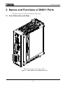
Width: 35mm, Height: 137mm, Depth: 125mm
Figure 2.1
Outer Dimensions and Sizes (unit: mm)
33
6 F 8 C 1 0 4 3
2.2 Names of DN611 Parts
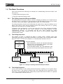
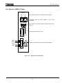
DN611
MS
NS
LED for module status / network status indication
7-segment LED for node address / error code
indication
NA / ERROR
ON
1 2 3
4
1
OSEN
2
BUSOFF
3
DR1
4
DR0
DIP switch for operation mode / communication rate
setting
Test connector (D-Sub, 9-pin)
LOADER
Black
Blue
Device side connector (connecting the DeviceNet)
White
Red
DeviceNet
Figure 2.2
Appearance (front panel)
34
6 F 8 C 1 0 4 3
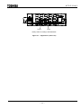
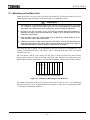
NA-H
NA-L
Rotary switch for setting node addresses
Figure 2.3
Appearance (side view)
35
6 F 8 C 1 0 4 3
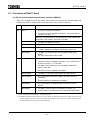
2.3 Functions of DN611 Parts
(1) LED for module status/network status indication (MS/NS)
This LED can light green/red. By making a distinction between green and red and lighting and
blinking, the DN611's module status (MS) and network status (NS) are indicated.
LED
Indication status
Meaning of the indication (main trouble)
MS
Not lit
• No power is supplied to the DN611.
• Though the power is supplied to the DN611, the module doesn't
become run mode (∗ 1).
When the 7-segment LED for node address/error code indicates the
local station node address, the power is supplied.
NS
Green lighting
• The DN611 is operating normally.
Green blinking
• The DN611 is reading switch settings.
Red blinking
• The DN611 is encountering a recoverable trouble.
→ Switch setting abnormal (DIP switch/rotary switch), etc.
Red lighting
• The DN611 is encountering a non-recoverable trouble (down
status).
You may need to replace the module.
Not lit
• No power is supplied to the DN611 (check MS).
• Though the power is supplied to the DN611, the module doesn't
become run mode ( ∗ 1); check MS.
• The DN611 is encountering a non-recoverable trouble (down
status); check MS.
• No network power is supplied to the DN611.
Green lighting
• The DN611 is normally communicating with slave devices.
Green blinking
• No communication between the DN611 and slave devices is
established.
• No slave devices are registered in the DN611.
Red blinking
• No communication is established with more than one slave
devices.
Red lighting
• The DN611 communication is stopped due to busoff (∗ 2).
• Communication is stopped due to the node address duplicated.
(* 1) See "4.6 Requests to the DN611" for the run mode.
(* 2) Busoff: Individual nodes on the DeviceNet check for abnormal transmission paths; when the local
node is judged to be the cause of the abnormal transmission path, the local node is separated from
the transmission path. This state is called busoff.
36
6 F 8 C 1 0 4 3
(2)
7-Segment LED for Node Address/Error Code Indication (NA/ERROR)
While the DN611 is normally transmitting data with slave devices the local station node address
is displayed.
Node address: A node identification number that the DeviceNet devices (nodes) linked to the
network have. The values range within 0 to 63 in decimal scale. In a DeviceNet,
the node address of a node linked to the network must be unique.
In the following cases, module or network status is displayed in combination of this LED and the
LED for module status/network status indication.
• A trouble occur on the DN611 or on the network.
• An error occurs when the S2T requests.
(Parameter setting and operation mode controlling, etc. are performed by the request from
the S2T.)
• The DN611 is downed.
See "6.2 Indications of the 7-Segment LED" for the combinations and meanings of this LED
and the LED for module status/network status indication.
(3)
DIP switch for setting the operation mode/communication rate
This DIP switch is used for setting the operation mode at DN611 busoff and a communication
rate on the network (500 kbps/250 kbps, 125 kbps).
"3.2 Switch Setting" explains the contents of the DIP switch and how to set it.
(4)
Rotary switch for node address setting (NA-H/NA-L)
Is used for setting node addresses in the network of the DeviceNet.
The DN611 can have a node address within 0 to 63 (decimal scale) unless the node address
doesn't duplicate with another node address (slave device) in the network.
"3.2 Switch Setting" explains how to set the rotary switch.
(5)
The test connector
This connector is only for maintenance. You may not use it.
(6)
The device side connector (for DeviceNet connection)
This connector is for connecting the DeviceNet cable to the DN611.
"3.4 Connection with the Network" explains how to connect cables.
37
6 F 8 C 1 0 4 3
3. Preparation for Operation (hardware)
3.1 DN611 Setting Flowchart (hardware)
DANGER
1.
Configure an emergency-stop circuit, interlock circuit, and/or other similar safety circuits
outside the PC and DN611.
If the PC or DN611 gets failed or malfunctioned, it can cause an accident which will lead to
bodily injury and/or mechanical damage.
CAUTION
2.
Secure the safe environment before executing program modification, forcible output, RUN,
or HALT instruction during operation. An operational mistake can cause mechanical
damage or accident
The following flowchart shows the DN611 setting.
Start
Set the node address for the DN611 with the rotary
switch on the side. Also set the operation mode and
communication rate with the DIP switch on the front
panel.
See '3.2 Switch Setting" for detail.
Setting your DN611's node address /
operation mode / communication rate
Mount the DN611 into the I/O slot of the S2T base
unit.
See "Mounting module" in the Main Unit User’s
Manual for detail.
Mounting the DN611 on the I/O slot of
the S2T
Connecting the DN611 to the network
Using the network side connector (attached to
DN611) , connect the DeviceNet cables to the DN611.
See "3.4 Connection with the Network" for detail.
Supplying the network power to the DN611
Supply the communication power for the DeviceNet
devices through the network cable.
See "3.5 The Network Power / Grounding" for detail.
Supplying the S2T power
After completing the above work, switch ON the power
of the S2T.
See "Grounding" and "Power-supply Wiring" in the
Main Unit User’s Manual for the details of
power-supply wiring / grounding.
End
Figure 3.1
DN611 Setting Flowchart
38
6 F 8 C 1 0 4 3
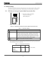
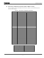
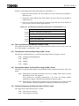
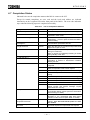
3.2 Switch Setting
The DN611 has a DIP switch on the front panel and a rotary switch on the side. These switches
are used for setting the operation mode, communication rate, and node address of the DN611.
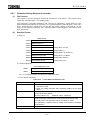
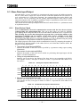
3.2.1
DIP Switch for Setting the Operation Mode/Communication Rate
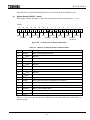
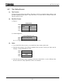
∼∼∼∼∼∼∼∼∼∼∼∼∼∼∼∼∼∼∼∼∼∼∼∼∼∼∼∼∼∼∼∼∼∼
← DIP switch for setting the operation
ON
mode/communication rate
1 2 3 4
Factory setting: OFF
1
OSEN
2
BUSOFF
3
DR1
4
DR0
LOADER
∼∼∼∼∼∼∼∼∼∼∼∼∼∼∼∼∼∼∼∼∼∼∼∼∼∼∼∼∼∼∼∼∼∼
Figure 3.2
DIP Switch for Setting the Operation Mode/Communication Rate
Table 3.1
DIP Switch Setting
DIP Switch Name
Function
1
OSEN
Is reserved for the system. Set to OFF and keep it.
2
BUSOFF
Specifies the operation mode when the DN611 turns busoff (*1).
ON: When turned busoff, the DN611 initializes the internal network
controller to become standby mode. After solving the cause of the
busoff state, resume transmission with the instruction from the S2T.
OFF: When turned busoff, the DN611 initializes the internal network
controller before resuming transmission (factory setting).
3
4
DR1
DR0
Sets the communication rate. Refer to Table 3.2.
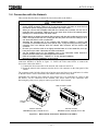
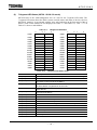
(*1) Busoff: Individual nodes on the DeviceNet check for abnormal transmission paths; when the local
node is judged to be the cause of abnormal transmission path, the local node is separated from the
transmission path. This state is called busoff.
Table 3.2
Communication Rate Setting
Communication Rate
DR1
DR0
125 kbps
OFF
OFF
250 kbps
OFF
ON
500 kbps
ON
OFF
Setting disabled
ON
ON
39
← Factory setting
6 F 8 C 1 0 4 3
CAUTION
1.
Set and keep "OSEN" on the DIP switch to OFF. Setting it to ON can get failed or
malfunctioned.
2.
When you set "BUSOFF" on the DIP switch to OFF, transmission will restart
automatically even when busoff occurs. Unless the cause of the DN611's busoff (cause of
communication error) is solved, however, busoff may get repeated.
3.
When you set both of communication rate DR0 and DR1 to ON and turn on the power of
the S2T, "Communication Rate Setting Failed" will appear with the following indications:
• The "MS" LED is blinking red.
• "F7" and the local station node address are being displayed alternately on the
7-segment LED.
To clear these indications, set DR0 and DR1 correctly and, issue a reset request or
turn OFF and ON the power.
4.
Set the communication rates of your nodes being connected to the network, to the same
communication rate. Setting different communication rates on your different
nodes will cause slave devices or the DN611 to get malfunctioned,
resulting in no communication started.
Read the relevant manuals and descriptions to set the communication rate of your slave
devices.
5.
Don't change over the communication rates while your S2T is rising just after the turning on
the power. In particular, never change the communication rate while communicating with
slave devices. Failing to do so will cause "Communication Rate Setting Failed" to appear.
To clear this indication, set the DIP switch to the correct setting and, issue a reset
request or turn OFF and ON the power.
Usage Recommendation
1.
Use a small minus screwdriver for changing the value of the DIP switch.
40
6 F 8 C 1 0 4 3
3.2.2
Rotary Switch for Node Address Setting
The DN611 board has a rotary switch for node address (0 to 63 in decimal scale) setting (Figure
3.3). NA-H is used for setting a 10-order figure while NA-L is used for setting a 1-order figure.
Since both of NA-H and NA-L can set a value from 0 to 9, the value can range within 0 to 99.
When a value within 64 to 99 is set, however, a "Node Address Setting Abnormal" error occurs
with the DN611 when the S2T power is switched ON.
To clear the error, set the correct node address and, issue a reset request or switch OFF and
ON the power. In the DeviceNet, each of the node address values in the network must be
unique.When the DN611's node address duplicates with another node address, a "Node Address
Duplicated" error occurs with the DN611 when it turns run status. To clear the error, allocate
the correct node address and, issue a reset request or switch OFF and ON the power.
NA-H
NA-L
Factory setting = "0"
Figure 3.3
Rotary Switch for Node Address Setting
CAUTION
1.
When you set a value within 64 to 99 to the node address of your DN611 and turn ON the
power of your S2T, "Node Address Setting Failed" will appear with the following
indications:
• The "MS" LED is blinking red.
• "F6" and the local station node address are being displayed alternately on the
7-segment LED.
To clear these indications, set the correct value to the node address and, issue a reset
request or turn OFF and ON the power.
2.
If your DN611 node address has the same value with another node and when the DN611
comes into run state, "Node Address Duplicated" will appear with the following indications:
• The "MS" LED is lighting red and/or the "NS" LED is lighting red.
• "70" and the local station node address are being displayed alternately on the
7-segment LED.
To clear these indications, set the correct value to the node address and, issue a reset
request or turn OFF and ON the power.
Usage Recommendation
1.
Use a small minus screwdriver for changing values of the rotary switch.
41
6 F 8 C 1 0 4 3
3.3 Mounting in the Base Unit
Mount your DN611 in the I/O slot of the base unit for the S2T and lock the master device. See
"Mounting/Removing the Module" in the Main Unit User’s Manual for detail.
CAUTION
1.
Since the DN611 is designed for Toshiba's S2T, be sure to mount your DN611 in the base
unit, instead of using it in stand-alone; don't use it for other applications. Unauthorized
applications can cause electric shock, bodily injury, and/or mechanical malfunction.
2.
Be sure to turn OFF the power (on the S2T side and network side) before attaching or
detaching the DN611 and/or the terminal block. Failing to do so will cause electric shock,
malfunction, and/or failure.
3.
Keep the DN611 free from foreign matter such as electric-wire waste. Failing to do so
could cause fire, failure, and/or malfunction.
4.
Check the connectors, cables, and base unit of the DN611, for their firm connection and
mounting using stoppers and screws. Note loose connection or mounting can be shaky or
easily disconnected off, resulting in failure or malfunction of the DN611.
More than one unit of DN611 can be mounted for one unit of the S2T, as explained in "1.5.2
Number of Mounting Modules." The DN611 can be mounted in the basic base unit and an
extended base unit.
Since the DN611 falls in a low-voltage I/O unit, place it at the left side of the unit, whereas
arrange high-voltage I/O units at the right side of the unit. Separate low-voltage units from
high-voltage units when wiring them ("8.4 Network Installation" explains network cables wiring).
P
S
S
2
T
D
N
6
1
1
D
N
6
1
1
Using the Basic Base Unit BU648E
Figure 3.4
Example of Mounting on the Base Unit
The current consumption of the S2T side power of the DN611 (DC5V) is 0.5 A. To examination
the power capacity, refer to "Examining the Power Capacity" of the S2T User’s Manual, besides
"1.5.2 Number of Mounting Modules."
42
6 F 8 C 1 0 4 3
3.4 Connection with the Network
This section describes how to connect the DeviceNet cable to the DN611.
CAUTION
1.
2.
3.
4.
5.
6.
Do not engage in attaching or detaching the DeviceNet cable with network side connector
during network operation. Failing to do so can cause reverse connection or short circuit of
the network power, resulting in no communication with other nodes.
When you connect the DeviceNet cable with the network side connector, be sure not to
make the wrong connection. Failing to do so can cause short circuit of the network power,
resulting in no communication with other nodes.
Neither attach nor detach the network side connector with the device side connector on the
DN611 front panel while the S2T is rising just after the power is turned ON. Failing to do so
can cause the DN611 to fail or malfunction.
Attaching the opposite end of the network side connector with/from a device side
connector is not possible because of the specific form. Trying connecting the wrong end by
excessive force can damage both the network side connector and the device side
connector.
Be sure not to wire the cable in too tightly stretched state or in bent state.Also, don't put
heavy stuff on the cable. Otherwise, the cable could break.
Ask the qualified expert for the installation work of the DeviceNet cables because it
requires sufficient safety and noise-suppression measures.
Refer to DeviceNet Volume I, Release 1.3, for the standard installation.
Also see "8.4 Network Installation" in this manual.
The DN611 supports the plug connection connector(open type). It has two types of network side
connectors attached, as shown in Figure 3.5. Follow the order stated below to connect the
DeviceNet cable to the DN611.
1) Connect the Devicenet cable to the network side connector and fix it.
2) Insert the network side connector into the device side connector on the front panel of the
DN611.
The connector at the left-side figure below has the upper and lower rows with holes for cables
so that the DN611 can be connected in the middle of the network daisy chain.
Meanwhile, the connector at the right-side figure below has a row with holes for cables so that
the DN611 can be connected at the network end. Select either of the connectors after
discussing the point you are going to connect your DN611 in the network.
Hole to insert a cable
Hole to insert
a cable
Phoenix Contact
TMSTBP2.5/5-STF-5.08 AB GY AU
Figure 3.5
Phoenix Contact
MSTBP2.5/5-STF-5.08 AB GY AU SO
Network Side Connectors Attached to the DN611
43
6 F 8 C 1 0 4 3
3.4.1
(1)
Connecting DeviceNet Cables to Network Side Connector
Preparing DeviceNet Cables
Use an open-type cable end (2 power cables, 2 signal cables, and 1 drain cable in discrete state)
for DeviceNet cables, which will be connected with the network side connector of the DN611.
Or purchase such an open-type cable end in the commercial market.
∼∼∼∼∼∼∼∼∼∼∼∼∼∼∼∼∼∼∼∼
Color of cable coating
Description
Black
Power cable (V −)
Blue
Signal cable (CAN_L)
−
Shield/Drain
White
Signal cable (CAN_H)
Red
Power cable (V +)
5 to 7 mm
Approx. 30 mm
Figure 3.6
(2)
Processing of the DeviceNet Cable End
Connecting DevicNet cables to the network side connector
This section describes how to connect DeviceNet cables to network side connectors by using
Figure 3.5 at the left side (upper and lower rows with holes for inserting cables) on the preceding
page. As shown in Figure 3.7, loosen screws on the cable connectors beforehand. Match the
colors of the cable coatings with those of the network side connector before inserting the cables
into the connectors. Tighten the screws for fixing cables.
Cable fixing screw
Color indication
Network side connector
Black
Blue
White
Red
Shield/Drain
Screws for fixing cables in lower-row
holes is located on this side
Figure 3.7
Connecting Cables with Network Side Connector
44
6 F 8 C 1 0 4 3
3.4.2
Connecting the Network Side Connector to the DN611
Insert the network side connector into the device side connector on front panel of the DN611.
Note the network side connector cannot be attached upside down due to the specific form; don't
try to connect these connectors by force. Tighten the screws for fixing the network side
connector on the DN611.
Network connector
fixing screw
Figure 3.8
Mounting the Network Side Connector
45
6 F 8 C 1 0 4 3
Usage Recommendation
1.
Loosen the cable fixing screw on the connector before inserting cables into the network
side connector. The cable cannot be fixed when the screws are kept tightened.
2.
Colors corresponding to cable colors are printed by the device side connector of the
DN611. Match the cable colors with the printed colors to have correct wiring.
3.
The DN611 and the DN311 (DeviceNet module for the T3/T3H) have different directions for
attaching the network side connector.
4.
DeviceNet cables, power tap, and device tap (connecting the trunk line with drop lines) are
necessary when constructing a system using a DeviceNet. Refer to "3.6 The Network
Components" for detail.
Some of the network components must be prepared by the user.
5.
When you use the network side connector that has the upper and lower rows with holes for
cables (at the left-side Figure 3.5), the connector protrudes from the left-side DN611 about
5mm. When you attach or detach the left-side module of DN611, you must detach the
connector from DN611.
46
6 F 8 C 1 0 4 3
3.5 The Network Power/Grounding
In the DeviceNet, the power for communication (24 Vdc) is supplied from the power cables
(V+/V−) for the DeviceNet cables via the network side connector. This section describes how
to supply the network power to the DeviceNet cables and how to configure network power units.
Grounding the network is also explained.
3.5.1 The Network Power Mechanism
In order to supply the network power (24 Vdc) to the DeviceNet cables, the power tap (Figure
3.9) specified in the DeviceNet must to be used. The power tap is an apparatus for connecting a
24 Vdc power unit to the trunk cable. It has the following functions:
1) When more than one 24 Vdc power unit are connected to one network, the power tap
prevents adverse current flow to power units by potential differences.
2) The power tap supports a maximum of 16 A from a power unit directly connected to the tap.
3) The protective circuit (fuse or circuit breaker) restricts the current flow from the power tap
to the cables within 8 A.
4) Provides terminals for grounding the network.
Power tap
Signal CAN_H
Signal CAN_L
Shield/Drain
DeviceNet
cables
Trunk cable
V−
Protective Protective
circuit
circuit
V+
Shot key
diode
Grounding terminal
V − V+
Network power-supply unit
The maximum cable length from
a power-supply unit to the power
tap is 3 meters.
Figure 3.9
Power Tap Configuration
The following power tap products, specified in the DeviceNet, are available.
Model name
1485T-P2T5-T5
(PowerTap)
Manufacturer
Rockwell Automation
47
6 F 8 C 1 0 4 3
3.5.2
How to Configure Network Power Units
This section describes selecting and disposing power units for supplying the network power to
individual nodes of the DeviceNet.
Maximum Current on the DeviceNet cable
The network power of the DeviceNet is set to rated 24 Vdc. The current which can be passed
on the network cable is as follows:
• Trunk line of thick cable: 8 A
Cable length
0m
25m
50m 100m 150m 200m 250m 300m 350m 400m 450m 500m
Max. current (A)
8.00
8.00
5.42
2.93
2.01
1.53
1.23
1.03
0.89
0.78
0.69
0.63
Maximum
Thick
cable
Current
Maximum
of Thick
Current
Cable
太ケーブル最大電流
ケーブル長
Cable
length
Figure 3.10
Current of the Trunk Line (thick cable)
48
500m
450m
400m
350m
300m
250m
200m
150m
100m
50m
8.00
7.00
6.00
5.00
4.00
3.00
2.00
1.00
0.00
0m
電流値(A)
Current value (A)
(1)
6 F 8 C 1 0 4 3
• Trunk line of thin cable: 3 A (up to 100 m)
Cable length
0m
10m
20m
30m
40m
50m
60m
70m
80m
90m 100m
Max. current (A)
3.00
3.00
3.00
2.06
1.57
1.26
1.06
0.91
0.80
0.71
0.64
Maximum
Current of Thin Cable
細ケーブル最大電流
電流値(A)
Current value (A)
3.00
2.50
2.00
1.50
1.00
0.50
100m
90m
80m
70m
60m
50m
40m
30m
20m
10m
0m
0.00
ケーブル長
Cable
length
Figure 3.11
• For drop line: 0.75 to 3.0 A
Current of the Trunk Line (thin cable)
Formula:
I = 4.57/L (however, I < 3 A)
I : Max. current of drop line (A)
L : Drop line length (0 to 6 m)
Usage Recommendation
1.
Consider not only current capacity of the trunk line but also current capacity of a drop line
when you install a node on the drop line.
2.
In particular, when you are connecting nodes in daisy chain on a drop line, be careful not
to have insufficient current capacity.
49
6 F 8 C 1 0 4 3
(2)
How to Know the Optimal Arrangement of Network Power Units
Use the following procedure to know optimal arrangement of network power units.
a) Obtain the sum of the network currents consumed by individual nodes on the network. For
the nodes which use the network power to operate, uses the sum of both currents.
b) Measure the full length of the network.
c) Based on the cable type (thick cable, thin cable) used for the trunk line and the full length of
the network obtained through procedure b), get the maximum current value available on the
cable by using Figure 3.10 and Figure 3.11
d) When the sum of the currents consumed on the network (procedure a) is smaller than the
maximum current available on the cable (procedure c), a network power unit installed at the
network end can be used to supply the power to all nodes ( = single power unit terminal
connection).
e) When the sum of the currents consumed on the network (procedure a) is larger than the
maximum current available on the cable (procedure c), install a network power unit near the
center of the network and examine whether it can supply the power to all nodes (= single
power unit central connection).
f) If the single power central connection is insufficient to supply the network power to all nodes,
install additional network power units.
Usage Recommendation
3.
(3)
Use a network power whose capacity is much larger than the total current consumption
necessary for the network.
Single Power Unit Terminal Connection
Below is an example of a network power unit installed at the end of the trunk line (thick cable)
with a total extension of 200 meters. The current consumption by the node is shown below.
V +−
Power tap
Node 1
V−
0.1A
Node 1
0.15A
Node 1
0.05A
Node 1
0.25A
Node 1
0.1A
200 m
Network
power-supply
unit
a)
b)
c)
d)
Sum of current consumption = 0.1A + 0.15A + 0.05A + 0.25A + 0.1A = 0.65 A
Total of power cable length extended = 200 m
Maximum current = 1.53 A available on the cable, based on Figure 3.10
Since the sum of current consumption < maximum current, a single power-supply
terminal connection can supply the power to all nodes.
e) Install a network power-supply unit with a rated current of 0.65 A or more.
(Select one with ample current in considering usage conditions.)
3.12
Example of Single Power Terminal Connection
50
6 F 8 C 1 0 4 3
(4)
Single Power Unit Central Connection
This section describes an example of installing a network power unit at the center of the trunk
line (Thick cable) with a total extension of 240 meters. The current consumption by the node is
shown below. Since the network power unit is installed at the center, the maximum current can
be supplied to all directions of the network.
Section 1
120 m
Section 2
120 m
V +−
Node 3
0.1A
Node 2
Power
tap
Node 1
0.25A
Node 4
V−
0.2A
Node 5
0.15A
Node 6
0.25A
0.15A
Network
power-supply
unit
Figure 3.13
Example of Single Power Unit Central Connection
a) Sum of current consumption in section 1 = 0.1A + 0.25A + 0.2A = 0.55A
a') Sum of current consumption in section 2 = 0.15A + 0.25A + 0.15A = 0.55A
b) Total length extended in section 1 = Total length extended in Section 2 = 120 m
c) Maximum current available on the cable based on Figure 3.10 = approx. 2.56 A
(Obtain the approximate value between 100 to 150 meter straight cable.)
d) Since the sum of current consumption < maximum current, a single power unit central
connection can supply the power to all nodes.
e) Install a network power unit with a rated current of 1.1A or more.
(Select one with ample current in considering usage conditions.)
When the current consumption by the section exceeds the maximum current available for the
cable in single power unit central connection, take measures in the table below. Figure 3.14
indicates an example of an overloaded single power unit central connection.
Cable section where the current is
applied beyond the maximum current
Countermeasure
Only one of the two section
Move a node in the overloaded section to the other
section.
Move the power tap closer to the section
overloaded.
Both sections
Use two power taps.
51
6 F 8 C 1 0 4 3
Section 1
120 m
Section 2
120 m
V +−
Node 3
1.1A
Node 2
Node 1
1.25A
Power
tap
V−
0.5A
Node 4
Node 5
0.25A
Node 6
0.25A
0.85A
Network
power-supply
unit
Figure 3.14
Example of Overloaded Single Power Unit Central Connection
a) Sum of current consumption in section 1 = 1.1A + 1.25A + 0.5A = 2.85A
a') Sum of current consumption in section 2 = 0.25A + 0.25A + 0.85A = 1.35A
b) Total length extended in section 1 = Total length extended in Section 2 = 120 m
c) Maximum current available on the cable based on Figure 3.10 = approx. 2.56A (Obtain the
approximate value between 100 to 150 meter straight cable.)
d) Since the sum of current consumption in section 1 > maximum current, the current is
overloaded.
Solution: Move the power tap to the overcurrent section. See Figure 3. 15.
52
6 F 8 C 1 0 4 3
Section 1
100 m
Section 2
140 m
V +−
Node 3
1.1A
Power
tap
Node 2
Node 1
V−
1.25A
0.5A
Node 4
0.25A
Node 5
Node 6
0.25A
0.85A
Network
power-supply
unit
Figure 3.15
Example of Solving the Overload
a) Sum of current consumption in section 1 = 1.1A + 1.25A = 2.35A
a') Sum of current consumption in section 2 = 0.5A + 0.25A + 0.25A + 0.895A = 1.85A
b) Total length extended in section 1 = 100 m
b') Total length extended in section 2 = 140 m
c) Maximum current available on the cable in section 1, based on Figure 3.10 = approx. 2.19A
(Obtain the approximate value between 100 to 150 meter straight cable.)
d) Since both of the sums of current consumption in section 1/2 < maximum current, a single
power unit central connection can supply the power to all nodes.
e) Install a network power unit with a rated current of 4.2A or more.
(Select one with ample current in considering usage conditions.)
53
6 F 8 C 1 0 4 3
3.5.3
The Network Power Unit (24 Vdc)
The network power unit is not attached to the DN611; you have to buy such a unit in the
commercial market. Your network power unit must conform with the following specifications:
Item
Specification
Output voltage
24Vdc ± 1%
Output current
16A or less
Input fluctuation
Max. 0.3 %
Load fluctuation
Max. 0.3 %
Effects by the ambient temperature
Max. 0.03 % / °C
Input Voltage
120V ± 10 %
230V ± 10 % (if necessary) or
Automatic changeover within 95 to 250V
Input frequency
47 to 62 Hz
Output ripple
250 mVp - p
Output side capacity
Max. 7000 µF
Ambient temperature
During operation: 0 to 66°C ∗
When stored: −40 to 85°C
∗ : Rated output derating at 60°C is allowed.
Instantaenious max. output current
less than 65A (at peek)
Protection against overvoltage
Yes (No value specified)
Protection against overcurrent
Yes (Max. current: 125 %)
Startup time
250 ms by the 5% value of the max. output voltage
Overshoot on startup
Max. 0.2%
Stability
0 to 100% load (for all conditions)
Insulation
Between output - AC power unit; between output - case
grounding
Conformity
Required: UL
Recommended: FCC Class B, CSA, TUV, VDE
Ambiant humidity
20 to 90% (no dew)
Surge current capacity
10% of reserve capacity
Usage Recommendation
1.
Use a network power whose capacity is much larger than the total current consumption
necessary for the network.
54
6 F 8 C 1 0 4 3
3.5.4
The Network Grounding
For the DeviceNet, use 1-point grounding (class-3 grounding for control device only) for the
network grounding. If more than one point are grounded, the ground can loop. Conversely, the
network without being grounded is likely to malfunction due to external noises.
Use the power tap as the point for 1-point grounding. Connect the ground terminal of the power
tap with the FG terminal of the power unit before applying class-3 grounding for control device
only as shown in Figure 3.16. (Install a power tap near the center of the network and ground
from it).
When more than one power units are used in the network, apply grounding to a power tap near
the center of the network.
Use a grounding line with a maximum of 3 meters (#8AWG power line).
Power tap
Grounding
terminal
V−
Power tap
Grounding
termina l
V+
FG V − V +
Power-supply
unit
FG
V − V+
Power-supply
unit
Power tap grounded
Figure 3.16
V− V +
Power tap not grounded
How to Install Your Network
55
6 F 8 C 1 0 4 3
3.5.5
Procedure for Switching-ON/Shutting-OFF the Power
This section describes the order of switching on the slave devices power, the network power,
and the S2T side power before starting up the DN611. Check all device wiring and settings are
completed before switching ON in the following order.
(1)
When Starting up the System
a) The network power
b) The slave device power
c) The S2T side power
d) Activating the DN611 communication
The DN611 doesn't yet start communication when the S2T side power is switched ON. Set the
parameters of the local nodes and register the parameters of the slave devices in the scanning
list before engaging in communication start processing. See "5.2 Module Setting Procedure" for
detailed procedures.
CAUTION
1.
2.
3.
(2)
Be sure to turn ON the network power before turning ON the power of the DeviceNet
devices.
Some nodes of the slave devices use the network power as the operation power while other
slave devices indicate an error when their work power is not supplied. Therefore, be sure to
switch ON the network power. Also note unless the network power is switched ON, your
DN611 cannot start communication with slave devices.
Be sure the network power is supplied to all the nodes being connected with the network.
The node to which no network power is supplied could cause communication obstacle to
other nodes.
Make sure the power of all slave devices is switched ON before the DN611 begins
communication.
When the DN611 begins communication while the power of a slave device is not switched
ON, the DN611 will display an error message of no response from that device.
When Deactivating the System
a) The slave devices power
b) The network power
c) (HALT the operation mode of the S2T.)
d) The S2T side power
CAUTION
4.
5.
While network communications are operating, don't shut OFF the network power. Failing
to do so will cause the entire network communications to stop and, one of the nodes
become busoff state.
Switch OFF the S2T side power at last after the DN611 begins communication. This helps
the master device (DN611) to be recognized from the network and prevents slave devices
from malfunctioning.
56
6 F 8 C 1 0 4 3
3.6 The Network Components
This section explains the network components of the DeviceNet other than the master/slave
devices (Figure 3.17). Since peripheral devices are recommended on the following pages, which
are available in the commercial market, buy some of them when you need.
Multiport tap
Node
Terminal
resistor
Tap
Trunk line
Node
Node
Tap
Node
Node
Node
Terminal
resistor
Tap
Node
Node
Node
Multiport tap
Node
Drop line
Node
Node
Node
Figure 3.17
Example of DeviceNet Network Configuration
57
6 F 8 C 1 0 4 3
(1) Thick Cable (for trunk line)
Manufacturer: Rockwell Automation
(2)
Item name
Catalog No.
Remarks
1 m with connectors
1485C-P1N5-M5
2 m with connectors
1485C-P2N5-M5
Shieldded mini-connectors (male, female)
attached
3 m with connectors
1485C-P3N5-M5
5 m with connectors
1485C-P5N5-M5
10 m with connectors
1485C-P10N5-M5
50 m with no connector
1485C-P1-A50
150 m with no connectors
1485C-P1-A150
300 m with no connectors
1485C-P1-A300
Shielded mini-connectors 871A-TS5-NM3
(male) and 871A-Ts5-N3 (female) for
fixing
Thin Cable (for trunk line and drop line)
Manufacturer: Rockwell Automation
Item name
Catalog No.
Remarks
1 m with connectors
1485R-P1M5-C
2 m with connectors
1485R-P2M5-C
Discrete shielded mini-connector (male)
and open-type connector
3 m with connectors
1485R-P3M5-C
150 m with no connector
1485C-P1-C150
300 m with no connectors
1485C-P1-C300
600 m with no connectors
1485C-P1-C600
58
Used for linking an open-type connector
to an open-type connector in daisy chain.
Used when connecting the DeviceBox
Tap with an open-type connector
6 F 8 C 1 0 4 3
(3)
Tap/Multiport Tap
Manufacturer: Rockwell Automation
Item name
Catalog No.
Remarks
T-Port Tap
1485P-P1N5-MN5R1
T-branch (one drop line from the trunk
line)
Both the trunk line and drop line use a
cable with shielded mini-connectors.
(4)
DeviceBox Tap (2 ports)
1485P-P2T5-T5
DeviceBox Tap (4 ports)
1485P-P4T5-T5
DeviceBox Tap (8 ports)
1485P-P8T5-T5
2 drop lines from the trunk line
4 drop lines from the trunk line
8 drop lines from the trunk line
The trunk line cable and drop line cable,
connected with a DeviceBox Tap, are
open-type and discrete.
Others
Manufacturer: Rockwell Automation
Item name
Catalog No.
Remarks
Power Tap
1485T-P2T5-T5
Tap power capacity for the trunk line:
7.5 A
The trunk line connected with a
PowerTap with overcurrent protection
uses a discrete open-type connector (no
shielded mini-connector).
Terminator (male)
1485A-T1M5
Terminates the trunk line.
Terminator (female)
1485A-T1N5
These are used for a Thick Cable with
mini-connectors or T-Port Tap.
59
6 F 8 C 1 0 4 3
4. How to Handle Your DN611 (software)
This chapter describes the subjects necessary for using various functions of the DN611 in ladder
programs for the S2T. More specifically, the following subjects are explained in this chapter.
• Configuration and functions of the DN611 communication memory seeing from the S2T
• Functions and usage of various request instructions for operating the DN611
• DN611's response code to various request instructions (completion status)
Based on the subjects discussed in this chapter, Chapter 5 describes the procedures in the
DN611 for setting parameters, activating transmission, inputting/outputting data with slave
devices, and reading RAS information including event history, and introduces sample programs.
CAUTION
1.
Chapter 4 describes the subjects necessary for using diverse functions of the DN611 from
the S2T. Chapter 5 describes, based on the subjects explained in Chapter 4, setting the
DN611 parameters, activating transmission, inputting/outputting data with slave devices,
and the procedure for reading RAS information including event history, and sample
programs.
Write programs after understanding the contents. As sample programs are basic, you
need to examine your programs from beginning to end before applying them to actual
systems.
Usage Recommendation
1.
When your DN611 is going to be I/O registered in the S2T, leave blank for the slot where
the DN611 is installed.
After automatic allocation is performed, the DN611-installed slot is left blank.
60
6 F 8 C 1 0 4 3
4.1 Configuration of the DN611 Communication Memory
Indicated below is the configuration of the DN611 communication memory seeing from the
S2T.(Word address)
0000H
Input/output data area
263 words
0106H
0107H
RAS information area
456 words
02CEH
02CFH
Semaphore area
305 words
03FFH
Figure 4.1
(1)
DN611 Communication Memory Map
The Semaphore Area
This area is used for issuing requests from the S2T to operate the DN611 and for reading the
DN611 responses.
(2)
The RAS information Area
This area of the DN611 displays the DN611's module status, communication status with network
and slave devices.
(3)
The Input/Output Data Area
This area stores data to be exchanged between the DN611 and slave devices.
Output data from the S2T is written in this area, while input data is read from this area. This
area also have the output and input semaphore registers used for synchronous communications
between the DN611 and slave devices.
61
6 F 8 C 1 0 4 3
4.2 The Input/Output Data Area
This area stores data to be exchanged between the DN611 and slave devices. Output data from
the S2T is written in this area, while input data is read from this area.
This area also have the output and input semaphore registers used for synchronous
communications between the DN611 and slave devices. The addresses in Figure 4.2 indicate the
word addresses seen from the S2T.
0000H
Polling/Bit strobe input data area
128 words/2048 bits
007FH
0080H
Polling output data area
128 words/2048 bits
00FFH
0100H
Bit strobe output data area
4 words/64 bits
0103H
0104H
Bit strobe output data semaphore (1 word)
0105H
Polling output data semaphore (1 word)
0106H
Input data semaphore (1 word)
Figure 4.2
Input/Output Data Area Configuration
62
6 F 8 C 1 0 4 3
(1)
Input Data Semaphore Register (0106H: 1 word)
This semaphore register is used when inputting data into the S2T from the DN611 (effective
only for synchronous transmission mode). The register is used both in the polling mode / bit
strobe mode.
• DN611 side operation
The DN611 writes data, collected from the slave devices in the polling mode or the bit strobe
mode, into "polling / bit strobe input data area" before setting "1" to this register.
• S2T ladder program operation
The ladder program for the S2T monitors this register. When detecting "1" is written into this
register, the ladder program reads data from the "polling / bit strobe input data area" and then
writes "0" in the register before notifying the DN611 of read completion.
Write the value "0" only in this semaphore register.
(2)
Polling Output Data Semaphore Register (0105H: 1 word)
This semaphore register is used when outputting polling data to the DN611 from the S2T
(effective only for synchronous transmission mode).
• S2T ladder program operation
The ladder program writes data, to be outputted to the "polling output data area," to slave
device in the polling mode before writing "1" in this register, and then instructs the DN611 to
start output.
Write the value "1" only in this semaphore register.
• DN611 side operation
The DN611 monitors this register in the "scan interval wait time" cycle specified from the
S2T. When detecting "1" is set to this register, the DN611 outputs output data in the "polling
output data area" to slave devices. When the output is completed, "0" is set to the register.
The "scan interval wait time" is explained in "4.6.3 Parameter Setting Request (local
node)."
(3)
Bit Strobe Output Data Semaphore Register (0104H: 1 word)
This semaphore register is used when outputting bit strobe data to the DN611 from the S2T
(effective only for synchronous transmission mode).
• S2T ladder program operation
The ladder program writes data, to be outputted to slave devices in the bit strobe mode, into
the "bit strobe output data area" before writing "1" into this register, and then instructs the
DN611 to start output.
Write the value "1" only in this semaphore register.
• DN611 side operation
The DN611 monitors this register in the "scan interval wait time" cycle specified from the
S2T. When detecting "1" is set to this register, the DN611 outputs output data in the "bit
strobe output data area" to slave devices. When the output is completed, "0" is set to the
register. The "scan interval wait time" is explained in "4.6.3 Parameter Setting Request
(local node)."
63
6 F 8 C 1 0 4 3
(4)
The Bit Strobe Output Data Area (0100H - 0103H: 4 words)
Stores data that the DN611 outputs to slave devices in the bit strobe mode.
The ladder program for the S2T writes output data in this area. The transmitting data in the bit
strobe mode is fixed at 8 bytes (64 bits).
The corresponding relation of the bits in this area and the node addresses of the slave devices is
indicated below.
Table 4.1
(5)
Bit Strobe Output Data Area Configuration
F
E
D
C
B
A
9
8
7
6
5
4
3
2
1
0
0100H
15
14
13
12
11
10
9
8
7
6
5
4
3
2
1
0
0101H
31
30
29
28
27
26
25
24
23
22
21
20
19
18
17
16
0102H
47
46
45
44
43
42
41
40
39
38
37
36
35
34
33
32
0103H
63
62
61
60
59
58
57
56
55
54
53
52
51
50
49
48
The Polling Output Data Area (0080H - 00FFH: 128 words)
Stores data that the DN611 will output to slave devices in the polling mode.
The ladder program for the S2T writes output data in this area. The area has 128 words (2048
bits) in size; unless the data size that the DN611 sends to salve devices doesn't exceed this limit,
up to 63 slave devices are connectable with one DN611.
How to allocate output data to slave devices from this area is explained in "4.4 Allocating Slave
Data to the Input/Output Data Area"
(6)
The Polling/Bit Strobe Input Data Area (0000H - 007FH: 128 words)
Stores data collected by the DN611 from the slave devices in the polling mode and bit strobe
mode. The ladder program for the S2T read data from this area. The area has 128 words (2048
bits) in size; unless the data size that slave devices send to the DN611 doesn't exceed this limit,
up to 63 slave devices are connectable with one DN611.
How to allocate input data from slave devices to this area is explained in "4.4 Allocating Slave
Data to Input/Output Data Area"
Figure 4.3. shows an overview of the output data area/input data area.
S2T
Input data
register area
DN611
READ
instruction
WRITE
instruction
Output data
register area
Slave
Polling / Bit strobe
input data area
Polling
Polling
output data area
Slave
Bit strobe
Bit strobe
output data area
Figure 4.3
Overview of Input/Output Data Area
64
6 F 8 C 1 0 4 3
(7)
The usage of Output/Input Data Semaphore (for synchronous transmission
mode alone)
Figure 4.4 indicates the relation between output data semaphore (polling / bit strobe) and input
data semaphore. Oblique lines parts indicate each of the semaphore values is set to the "1".
S2T
Writes in output
data area
Reads from
input data area
Writes in output
data area
Writes
output
Writes read instruction
completion "1"
"0"
Writes output
instruction "1"
Output data
semaphore
Writes output
completion
"0"
Writes
output
completion "0"
Intput data
semaphore
DN611
Output
processing
Figure 4.4
(8)
Intput
processing
Output
processing
Use of Semaphores in Synchronous Mode
Cautions in Using the Input/Output Data Area
• The input data semaphore register is used both for the polling mode and the bit
strobe mode. Therefore, when some slave devices use the polling mode while other
slave devices use the bit strobe mode, set data input/output processing in the
alternative way like :
polling mode processing completion → bit strobe mode processing completion →
polling mode processing completion → bit strobe mode → …
• Don't allow the WRITE instruction to execute in the input data area/input data
semaphore register. Otherwise, input data could be destroyed.
• When you write data in the polling output data area/bit strobe output data area with
the WRITE instruction, be careful of the top address of the area and the data size to
be written. Otherwise, data could destroy those in another area, causing the DN611
and/or slave devices to get malfunctioned.
65
6 F 8 C 1 0 4 3
4.3 The RAS Information Area
This area indicates the DN611's module status and the communication status of the network and
slave devices. Don't write data into this area. Otherwise, the correct data may not be read. The
addresses in Figure 4.5 indicate the word addresses seen from the S2T.
0107H
Network power unit (1 word)
0108H
Operation mode on busoff (1 word)
0109H
Network communication rate (1 word)
010AH
Local station node address (1 word)
010BH
∼∼∼∼∼∼
∼∼∼∼∼∼
∼∼∼∼∼∼
∼∼∼∼∼∼
Input/Output data setting information (384 words)
∼∼∼∼∼∼
∼∼∼∼∼∼
∼∼∼∼∼∼
∼∼∼∼∼∼
028BH
Reserved (8 words)
0293H
Bit strobe no-response device (4 words)
0297H
Polling no-response device (4 words)
029BH
Number of polling devices (1 word)
029CH
Number of bit strobe devices (1 word)
029DH
Number of on-line devices
029EH
Number of total devices (1 word)
029FH
Configuration information (32 words)
02BFH
Node error counter (7 words)
02C6H
Completion of module initialization (1 word)
02C7H
Reserved (1 word)
02C8H
Polling/Bit strobe scan cycle (5 words)
02CDH
Down information (1 word)
02CEH
Station status (1 word)
Figure 4.5
RAS Information Area Configuration
66
6 F 8 C 1 0 4 3
Indicated below is detailed information that can be checked in the RAS information area.
(1)
Station Status (02CEH: 1 word)
This register indicates the DN611's status with bit flags. Each bit has meaning when "1" is set.
Format
15
14
DOWN
13
12
STBY
Reserved
11
10
Reserved
RUN
BITS
Figure 4.6
Table 4.2
9
8
POLL
7
Reserved
Reserved
5
4
TXERR
NCOIN
3
SYNC
START
2
1
0
DRADR
BUSOFF
Reserved
Configuration of Station Status Bits
Meaning of Individual Bits of Station Status
Bit
Name
Meaning
15
DOWN
DN611 is set to the down mode.
14
6
Reserved
13
STBY
DN611 is set to standby mode.
12
RUN
DN611 is set to run mode.
11
Reserved
10
BITS
Bit strobe mode transmission is operating.
9
POLL
Poling mode transmission is operating.
8
Reserved
7
Reserved
6
NCOIN
No slave device is registered in the DN611.
5
TXERR
Some of the salve devices registered do not respond.
4
START
DN611 is executing transmission.
3
SYNC
DN611 is operating in synchronous mode.
2
BUSOFF
DN611 is set to busoff status.
1
DPADR
DN611 detected an duplicated node address when starting transmission.
0
Reserved
Table 4.3 on the next page indicates the configuration of the station status bits of the DN611 in
different modes.
67
6 F 8 C 1 0 4 3
Table 4.3
DN611's Modes and Station statuses
DN611's mode
Bit "1"
Station status
a
Down mode
DOWN
8000H
b
After switching ON the power or after issuing a
reset request from the S2T
STBY
c
No slave device is registered (or deleted) in the
DN611 in mode b).
STBY
NCOIN
d
When a slave device is registered in mode c) by a
parameter setting request
STBY
e
When "standby" is requested by a module control
request from the S2T
STBY
f
When "transmission enabled, polling mode
transmission, asynchronous mode" is requested by
a module control request from the S2T and
transmitted normally
RUN
START
POLL
1210H
g
When "transmission enabled, bit strobe mode
transmission, asynchronous mode" is requested by
a module control request from the S2T and
transmitted normally
RUN
START
BITS
1410H
h
When "transmission enabled, polling mode and bit
strobe mode transmissions, asynchronous mode"
is requested by a module control request from the
S2T and transmitted normally
RUN
START
POLL
BITS
1610H
I
When asynchronous mode is requested in a mode
within f) to h)
j
While transmitting with a slave device in a mode
within f) to i), the slave device stopped responses.
The bits from f) to
i), followed by
TXERR
k
When busoff occurs, the DIP switch of the DN611
(BUSOFF) remains OFF (when the DN611 has
control of restarting transmission)
Station status bits before busoff
occurring, followed by :BUSOFF
l
When busoff occurs, the DIP switch of the DN611
(BUSOFF) remains ON (changing to standby mode
when busoff occurring)
STBY
BUSOFF
2004H
m
An overlapped node address is detected when
starting transmission
STBY
DPADR
2002H
68
Bits from f) to h),
followed by SYNC
2000H
2040H
2000H
2000H
1218H
1418H
1618H
1230H
1430H
1630H
1238H
1438H
1638H
6 F 8 C 1 0 4 3
(2)
Down Information (02CDH: 1 word)
This register stores the cause of becoming the down mode when the DN611 turns down mode.
When this happens, some of the following down codes are displayed in the 7-segment LED on
the front panel.
Table 4.4
(3)
Down Information
Down information
(hex.)
Cause of down mode occurred
F0H
Watchdog timeout occurred
F1H
Memory bus abnormal occurred
F2H
TRAP occurred
F3H
ROM's BCC check error occurred (on DN611 startup)
F4H
RAM's read/write error occurred (on DN611 startup)
F5H
Read/Write error occurred for the DN611 communication memory (on
DN611 startup)
F6H
DN611 node address setting abnormal
F7H
DN611 network communication rate setting abnormal
F8H
Configuration data EEPROM read error occurred
Polling / Bit Strobe Scan Cycle (02C8H - 02CCH: 5 words)
This area stores the DN611's scan time in milliseconds for the polling mode or bit strobe mode
transmission.
When in asynchronous mode: The "scan cycle" means the time that the DN611 starts carrying
out data input/output with all slave devices until starting the next input/output.
• Only for the slave devices with the polling mode, the "scan cycle" means the time from
starting polling input/output until starting the next polling input/output.
• Only for the slave device with the bit strobe mode, the "scan cycle" means the time
from starting bit strobe input/output until starting the next bit strobe input/output.
• For the salve devices where the polling mode and bit strobe mode are intermingled, the
"scan cycle" means the time from starting bit strobe input/output, followed by
performing polling input/output, until starting the next bit strobe input/output.
When in synchronous mode: The "scan completion time" means the time from the S2T's writing
"1" in the "bit strobe output data semaphore/polling output data semaphore" until the DN611's
writing "1" in the "input data semaphore."
Table 4.5
(4)
Scan Cycle Configuration
02C8H
Scan cycle/Scan completion time
02C9H
Asynchronous mode: Min. scan cycle value
02CAH
Asynchronous mode: Max. scan cycle value
02CBH
Synchronous mode: Min. scan cycle time value
02CCH
Synchronous mode: Max. scan cycle time value
Completion of module initialization (02C6H:1 word)
This register indicates the completion of initialization processing by switching ON the power or
by requesting resetting.
"1": Completion of initialization
"Value other than 1": Under initialization
69
6 F 8 C 1 0 4 3
(5)
The Node Error Counter (02BFH to 02C5H: 7 words)
The CAN controller used in the DN611 has a function of notifying error state changes of the
local station error state (error active ⇔ error passive ⇔ busoff) based on the number of
transmission errors occurring.
The CAN controller also has a function of notifying the DN611 of "overrun error" if the DN611
fails to take the data sent from slave devices.
The DN611 maintains the current error state and a history of error state changes since
communication was activated. This register indicates a history of error state changes since
communication was activated and the total number of transmission times and reception times.
Table 4.6
Node Error Counter Configuration
02BFH
Current error state (hexadecimal scale)
02C0H
Number of transmission times since communication was activated
02C1H
Number of reception times since communication was activated
02C2H
Number of error active occurrence times
02C3H
Number of error passive occurrence times
02C4H
Number of busoff occurrence times
02C5H
Number of overrun error occurrence times
Current error state
Error code (hexadecimal scale)
Initial mode
00H
Error active state
01H
Error passive state
02H
Busoff state
03H
Overrun error occurrence
04H
Reserved
Other
70
6 F 8 C 1 0 4 3
(6)
Slave Device Configuration Information (029FH - 02BEH: 32 words)
This area indicates scan type information for slave devices, which is set in the DN611(stored in
the non-volatile memory).
Table 4.7
Slave Device Configuration Information
Address
F
8
7
0
029FH
Node address : 1
Node address : 0
02A0H
Node address : 3
Node address : 2
02A1H
Node address : 5
Node address : 4
02A2H
Node address : 7
Node address : 6
02A3H
Node address : 9
Node address : 8
02A4H
Node address : 11
Node address : 10
02A5H
Node address : 13
Node address : 12
02A6H
Node addres s : 15
Node address : 14
02A7H
Node address : 17
Node address : 16
02A8H
Node address : 19
Node address : 18
02A9H
Node address : 21
Node address : 20
02AAH
Node address : 23
Node address : 22
02ABH
Node address : 25
Node address : 24
02ACH
Node address : 27
Node address : 26
02ADH
Node address : 29
Node address : 28
02AEH
Node address : 31
Node address : 30
02AFH
Node address : 33
Node address : 32
02B0H
Node address : 35
Node address : 34
02B1H
Node address : 37
Node address : 36
02B2H
Node address : 39
Node address : 38
02B3H
Node address : 41
Node address : 40
02B4H
Node address : 43
Node address : 42
02B5H
Node address : 45
Node address : 44
02B6H
Node address : 47
Node address : 46
02B7H
Node address : 49
Node address : 48
02B8H
Node address : 51
Node address : 50
02B9H
Node address : 53
Node address : 52
02BAH
Node address : 55
Node address : 54
02BBH
Node address : 57
Node address : 56
02BCH
Node address : 59
Node address : 58
02BDH
Node address : 61
Node address : 60
02BEH
Node address : 63
Node address : 62
Scan type
Code (hexadecimal)
Unassigned
Bit strobe mode
Polling mode
Polling & strobe
Reserved
00H
01H
02H
03H
Other
71
6 F 8 C 1 0 4 3
(7)
The Number of Total Devices (029EH: 1 word)
Indicates the number of the slave devices, operable on the network, specified by a parameter
setting request from the S2T (setting information)
(8)
The Number of Online Devices (029DH: 1 word)
Indicates the number of the slave devices which are performing data input/output with the
DN611 (execution information).
(9)
The Number of Bit Strobe Devices (029CH: 1 word)
Indicates the number of the bit strobe mode slave devices, operable on the network, specified by
a parameter setting request from the S2T (setting information).
(10) The Number of Polling Devices (029BH: 1 word)
Indicates the number of the polling mode slave devices, operable on the network, specified by a
parameter setting request from the S2T (setting information).
Note: For the slave devices which support both the polling mode and bit strobe mode, both of the
bit strobe devices and polling devices are counted.
(11) The Polling No-Response Device Map (0297H - 029AH: 4 words)
Indicates, per bit, the individual polling-mode devices not responding to the transmission from the
DN611.The value in each frame in Table 4.8 indicates the node address of a slave device.
When a slave device becomes not responding, the corresponding bit turns ON. The bit for the
normal slave device is set to OFF. The corresponding bit for the slave device not selected is also
set to OFF.
F
E
D
C
B
A
9
8
7
6
5
4
3
2
1
0
0297H
15
14
13
12
11
10
9
8
7
6
5
4
3
2
1
0
0298H
31
30
29
28
27
26
25
24
23
22
21
20
19
18
17
16
0299H
47
46
45
44
43
42
41
40
39
38
37
36
35
34
33
32
029AH
63
62
61
60
59
58
57
56
55
54
53
52
51
50
49
48
Table 4.8
Polling No-Response Slave Devices
(12) The Bit Strobe No-Response Device Map (0293H - 0296H: 4 words)
Indicates, per bit, the individual bit-strobe mode salve devices not responding to the transmission
from the DN611. The value in each frame in Table 4.9 indicates the node address of a slave
device. When a slave device becomes not responding, the corresponding bit turns ON. The bit
for the normal slave device is set to OFF. The corresponding bit for the slave device not selected
is also set to OFF.
F
E
D
C
B
A
9
8
7
6
5
4
3
2
1
0
0293H
15
14
13
12
11
10
9
8
7
6
5
4
3
2
1
0
0294H
31
30
29
28
27
26
25
24
23
22
21
20
19
18
17
16
0295H
47
46
45
44
43
42
41
40
39
38
37
36
35
34
33
32
0296H
63
62
61
60
59
58
57
56
55
54
53
52
51
50
49
48
Table 4.9
Bit Strobe No-Response Slave Devices
72
6 F 8 C 1 0 4 3
(13) Input/Output Data Setting Information (010BH - 028AH: 384 words)
Indicates , per slave device (node address: NA), the allocations of input/output data for slave
devices in the input/output data area. The input/output data setting information has 6 words per 1
slave device.
Figure 4.7 indicates the top addresses of areas where individual node information is stored. Table
4.10 lists the meanings per slave device.
After the slave device parameters are set, data will be input in these areas when the
DN611 is set to run mode (transmission enabled status) by an operation mode control
request.
"0" is set to the areas where no slave device is found.
010BH
NA = 0
018FH NA = 22
0213H
NA = 44
0111H
NA = 1
0195H NA = 23
0219H
NA = 45
0117H
NA = 2
019BH NA = 24
021FH
NA = 46
011DH
NA = 3
01A1H NA = 25
0225H
NA = 47
0123H
NA = 4
01A7H NA = 26
022BH
NA = 48
0129H
NA = 5
01ADH NA = 27
0231H
NA = 49
012FH
NA = 6
01B3H NA = 28
0237H
NA = 50
0135H
NA = 7
01B9H NA = 29
023DH
NA = 51
013BH
NA = 8
01BFH NA = 30
0243H
NA = 52
0141H
NA = 9
01C5H NA = 31
0249H
NA = 53
0147H
NA = 10
01CBH NA = 32
024FH
NA = 54
014DH
NA = 11
01D1H NA = 33
0255H
NA = 55
0153H
NA = 12
01D7H NA = 34
025BH
NA = 56
0159H
NA = 13
01DDH NA = 35
0261H
NA = 57
015FH
NA = 14
01E3H NA = 36
0267H
NA = 58
0165H
NA = 15
01E9H NA = 37
026DH
NA = 59
016BH
NA = 16
01EFH NA = 38
0273H
NA = 60
0171H
NA = 17
01F5H NA = 39
0279H
NA = 61
0177H
NA = 18
01FBH NA = 40
027FH
NA = 62
017DH
NA = 19
0201H NA = 41
0285H
NA = 63
0183H
NA = 20
0207H NA = 42
0189H
NA = 21
020DH NA = 43
Figure 4.7
Input/Output Data Setting Information Addresses
73
6 F 8 C 1 0 4 3
Example) Input/output data setting information for node address = 1
• Input data offset indicates the offset address (in bytes) from the top (0000H) of
input data area.
• Output data offset indicates the offset address (in bytes) from the top (0080H) of
output data area.
• There are no items for the offset of bit strobe output data and for the number of
bytes because of the bit strobe output data area.
Table 4.10
Input/Output Data Setting Information for Node Address = 1
0111H
Bit strobe input data offset
0112H
Number of bit strobe input data bytes
0113H
Polling input data offset
0114H
Number of polling input data bytes
0115H
Polling output data offset
0116H
Number of polling output data bytes
(14) The Local Station Node Address (010AH:1 word)
The hexadecimal node address of the local station, specified with the rotary switch on the side
face of the module, is stored (00H - 3FH).
(15) The Network Communication Rate (0109H:1 word)
The network communication rate, set with the DIP switch on the front panel, is stored.
00H: Unassigned (setting disabled)
01H: 500kbps
02H: 250kbps
03H: 125kbps
(16) The Operation Mode on Busoff Occurring (0108H:1 word)
The DN611's operation mode setting is stored when the DN611 detects busoff state of the local
station.
00H: When busoff is detected, the module will be set to standby mode, followed by the
initialization of the CAN controller.
The procedure for resuming transmission is the same for starting ordinary
transmission. Chapter 5 describes the transmission start procedure.
01H: When busoff is detected, the operation mode of the module is left intact, and the
CAN controller is initialized, followed by resuming communication, if possible.
(17) Yes/No of Supplying the Network Power (0107H:1 word)
The supply mode of the network power is stored.
00H: Network power normal
01H: Network power abnormal
74
6 F 8 C 1 0 4 3
4.4 Allocating Slave Device Data to the Input/Output Data Area
Reception/transmission data of slave devices will be allocated to the input/output data area in the
order from smaller to larger node addresses. For example, in Table 4.11, Slave Device
Configuration, the input data area/output data area is allocated to the top and the subsequent
addresses without skipping, as shown in Figure 4.8. Allocation will be executed when run mode
(transmission state enabled) is set by an operation mode control request after setting slave
device parameters.
Table 4.11
Slave Device Configuration (sample)
Node address
Transmission size
Reception size
10
2 bytes
4 bytes
11
4 bytes
2 bytes
12
6 bytes
6 bytes
20
3 bytes
4 bytes
30
4 bytes
1 byte
40
4 bytes
6 bytes
0080H
0081H
0082H
Output data area
Input data area
F· · · · · · · · · · · ·
· · · · 0
F· · · · · · · · · · · ·
· · · · 0
NA = 10
0000H
0001H
NA = 11
0002H
0083H
0084H
NA = 12
0004H
0089H
008AH
008BH
NA = 12
0005H
0086H
0088H
NA = 11
0003H
0085H
0087H
NA = 10
NA
No allocation
0006H
= 20
0007H
0008H
NA = 30
NA = 20
No allocation
NA = 30
0009H
000AH
NA = 40
NA = 40
000BH
∼∼∼∼∼∼∼∼∼∼∼∼∼∼∼∼∼∼∼∼∼∼∼∼∼∼∼∼∼∼
∼∼∼∼∼∼∼∼∼∼∼∼∼∼∼∼∼∼∼∼∼∼∼∼∼∼∼∼∼∼
∼∼∼∼∼∼∼∼∼∼∼∼∼∼∼∼∼∼∼∼∼∼∼∼∼∼∼∼∼∼
∼∼∼∼∼∼∼∼∼∼∼∼∼∼∼∼∼∼∼∼∼∼∼∼∼∼∼∼∼∼
Figure 4.8 Input/Output Data Area in Slave Device Configuration (sample)
CAUTION
1.
2.
3.
When a slave device has odd transmission/reception bytes in size, the actual size plus 1
byte are allocated in the DN611 input/output area.
When you add a new slave device, enter a new value larger than the node addresses of the
present slave devices. For Figure 4.8, enter a value larger than "41"for the node address of
a new slave. If the node address of a new slave device is set to "18", allocating data area of
node addresses 20/30/40 will be shifted.
Don't change the input/output data size for slave devices (FLEX-I/O, etc.) which are flexible
in data allocation size. If changed, the slave devices with a node address larger than that of
the slave device changed data size will be shifted in their data allocation.
75
6 F 8 C 1 0 4 3
4.5 The Semaphore Area
This area is used for issuing a request from the S2T for operating the DN611, or for reading the
DN611's response to a request. The addresses in Figure 4.9 indicate the word addresses seen
from the S2T.
02CFH
Reserved (1 word)
02D0H
Acknowledgement area (100 words)
0334H
Request area (200 words)
03FCH
Acknowledgement flag register (1 word)
03FDH
Request flag register (1 word)
03FEH
Reserved (1 word)
03FFH
Request register (1 word)
Figure 4.9
The Semaphore Area Configuration
76
6 F 8 C 1 0 4 3
(1)
The Request Register (03FFH: 1 word): S2T → DN611
This register is used for notifying the DN611 of a request when the S2T issues the request to the
DN611. After writing "1" in the "request flag register," the ladder program of the S2T writes
"256 (0100H)" in this register.
"0": No notice.
"256": Noticed
After reading a request from the "request area," the DN611 sets this register to "0."
(2)
The Request Flag Register (03FDH: 1 word): S2T → DN611
This register is used when the S2T issues a request to the DN611. After writing request data in
the "request area," the ladder program of the S2T writes "1" in this register.
"0": No request.
"1": A request is issued from the S2T to the DN611
"Value other than 0 and 1": Reserved
The DN611 sets this register to "0" after reading a request in the "request area."
(3)
The Acknowledgement Flag Register (03FCH: 1 word): DN611 → S2T
This register is used for notifying the S2T of the DN611's response after the S2T issues a
request to the DN611. The ladder program of the S2T checks this register for "1" to be set after
a request is issued to the DN611. When "1" is set to this register, the ladder program reads
response data of the DN611 from the "acknowledgement area" before writing "0" in this register.
"0": No response.
"1": Responded to the S2T from the DN611
"Value other than 0 and 1": Reserved
(4)
The Request Area (0334H - 03FBH: 200 words): S2T → DN611
Request data is written when the S2T issues a request to the DN611.
The data is written in the area beginning "0334 H" as the top address.
The S2T has the following six types of requests to the DN611.
• Reset request
• Parameter setting request (local node)
• Parameter setting request (slave device)
• DN611 operation mode control request
• RAS information read request
• Time setting request
Each of the six requests has a different composition of request data, which is described in "4.6
Requests to the DN611."
(5)
The Acknowledgement Area (02D0H - 0333H: 100 words): DN611 → S2T
When the S2T issues a request to the DN611, the DN611 sets response data to the S2T to this
acknowledgment area. The response data is set at the addresses beginning "02 D0H." The
request data composition is described in "4.6 Requests to the DN611."
77
6 F 8 C 1 0 4 3
(6)
How to Use the Semaphore Area
Figure 4.10 illustrates the usage of the areas and registers discussed at (1) to (5).
The squares in oblique lines in the figure indicate that "1" has been set to the flag registers and
that "256" has been set to the request register.
a) Use a READ instruction to the acknowledgement flag register to check for "0."
If a value other than "0" is found, write "0" in this area (first time only)
b) Use a WRITE instruction to write request data to the DN611 in the request area (top
address: 0334H).
c) Use a WRITE instruction to write "1" in the request flag register.
d) Use a WRITE instruction to write "256" in the request register.
e) Use a READ instruction to read the acknowledgement flag register and waits until "1" is set
to the register.
f) Use a READ instruction to read response data of the DN611 from the acknowledgement
area when "1" is found in the acknowledgement flag register. (top address: 02DOH).
g) Use a WRITE instruction to write "0" in the acknowledgement flag register.
→ Returns to b).
S2T
Reading the
acknowledgement area
W riting in the
request area
Completes
reading the
acknowledge
-ment area
Reading the
acknowledgement
flag register
Requested
Request flag
register
Request notification
Request
register
Completing reading
the request area
Acknowl-edg
ement flag
register
Responded
DN611
internal processing
DN611
Reading the
request
area
Figure 4.10
(7)
Writing in the
acknowledgment area
How to Use the Semaphore Area on Requests
Cautions When Using the Semaphore Area
a) Since only a pair of request area and acknowledgment area is furnished, issue the
next request after the DN611 returns the acknowledgement to a request from the
S2T.
b) Don't write data (no WRITE instruction) in the acknowledgement area /
acknowledgement flag register. Otherwise, data could be destroyed.
c) When a WRITE instruction writes data in the request area, be careful of the top
address and the data size to be written. Failing to do so could lead to the destruction
of other data, causing the DN611 to get malfunctioned.
78
6 F 8 C 1 0 4 3
4.6 Requests to the DN611
This section describes different types of requests that the S2T issues to the DN611. There are
six such types of requests that the S2T issues to the DN611.
The six types of requests are classified into those executable and those not executable,
depending on the DN611's operation mode, which is explained in "4.6.1 The DN611 Operation
Modes." Table 4.12 lists the relation between different types of requests and the operation
modes.
The six types of requests are detailed in "4.6.2 Reset Request."
Table 4.12
Operatin mode
Request name
[request code]
Down mode
(DOWN)
List of Requests
Initialization
mode
(INIT)
Reset
[0011H]
Standby mode (STBY)
Run mode
Local node Local node
Parameters Parameters
unassigned
assigned
(RUN)
×
¡
¡
¡
Paremeter setting
(local node)[0012H]
×
×
¡
¡
×
Parameter setting
(slave device)[0012H]
×
×
¡
¡
×
Operation mode control
[0013H]
×
×
×
¡
¡
RAS information reading
[0015H]
¡
×
¡
¡
¡
Time setting
[0018H]
×
×
¡
¡
¡
¡ : Request enabled
: Though the request is enabled, an error could be responded depending on the down cause.
See "Table 4.4 Down Information" for the possible down cause.
×
: Request disabled ... When requested, an error is responded. The error codes are
explained in "4.7 Completion Status."
79
6 F 8 C 1 0 4 3
4.6.1
The DN611 Operation Modes
The DN611 has the following operation modes:
1) Initialize Mode
• The DN611 is in the process of resetting when the power is turned ON or reset is requested.
• The reset processing turns "standby mode" when the reset processing is completed
successfully.
• The reset processing turns "down mode" when the reset processing fails to complete
successfully (e.g, when an error occurs in self-testing).
• Don't issue an instruction from the user program of the S2T side during "initialize mode."
2) Standby Mode
• The DN611 turns this mode when the reset processing is completed successfully after you
turn ON the power or request resetting.
• An operation mode control request can changes run mode to standby mode.
• Only this mode allows you to set the parameters of the local node/slave devices to the
DN611.
• Unless the parameters of the local node is set, "run mode" cannot be set from this mode.
3) Run Mode
• After the parameters of the local node are set, an operation mode control request allows you
to change to run mode.
• This mode allows the DN611 to transmit to salve devices.
• This mode allows you to select a transmission mode (polling mode/bit strobe mode) with
slave devices.
• This mode allows you to select a transfer mode (synchronous/asynchronous mode) between
the S2T ⇔ DN611.
4) Down mode
• Indicates that the DN611 has turned unrecoverable abnormal state.
• A reset request can change to "standby mode." If such a reset request gets an error response,
turn OFF and ON the power for recovery.
• See "Table 4.4 Down Information" for the possible cause of the down mode.
Figure 4.11 illustrates transitions of the DN611 operation modes. Inside square frames indicates the
operation mode of the DN611. The operation mode in thick squared frame is the one that the user
program can control. The thick arrowheads indicate the request that the user program can specify.
Power downed
switch ON the power
Self-check completed successfully
Initialize
Standby
Reset request
a) Standby request
b) S2T: RUN → HALT
c) Busoff occurred
For the case BUSOFF on
DIP-SW on front panel remains
ON.
Run request
Self-check
completed
unsuccessfully
Reset request
Reset request
or
switch ON the power
Run
Down
Unrecoverable error occurred
Figure 4.11
(transmission enabled)
The DN611 Operation Modes
CAUTION
1.
If the S2T turns into HALT/ERROR mode, the DN611 in run mode becomes standby mode.
80
6 F 8 C 1 0 4 3
4.6.2
(1)
Reset Request
The Function
This request is used for resetting the DN611 from theS2T. When receiving a reset request, the
DN611 executes initialization of the module. This request also can delete the scan list
(parameters of the slave devices being linked to the network) saved in the internal non-volatile
storage of the DN611.
During normal operation:
When a reset request is executed, the DN611 turns waiting for a parameter setting request
(standby mode). No response will be made to the S2T when a reset request is completed
successfully. To confirm successful completion of the reset request, check the station status
(05D5H) for transiting from "initialize mode" to "standby mode."
When in abnormal state:
An error response (completion status) will be returned to the S2T when the request is not
accepted.
Reset request
Reset completion
INZ bit (14 bits)
STBY bit (12 bits)
NCOIN bit (6 bits)
(when clearing the scan list)
Station status
Figure 4.12
(2)
4000H
2000H/2040H
Station Status Operation on Reset Request
The Data Part Format
a) Request
0334H
0335H
Request area
Request code (0011H)
Scan list clear
0: Don't clear it / 1: Clear it
b) Acknowledgement (only for abnormal state)
02D0H
02D1H
Acknowledgement area
Request code (0011H)
Completion status
See "4.7 Completion Status" for the above completion status.
(3)
Execution Time: Since the S2T writes "1" in the request register until the station status
changes to "2000H/2040H" from "4000H"
• When the scan list is found in the non-volatile storage: Scan list is not cleared...Approx. 1 second
Scan list is cleared ...Approx. 9 seconds
• When no scan list is found in the non-volatile storage: No scan list cleared ...Approx. 9 seconds
Scan list is cleared ...Approx. 9 seconds
(4)
Others
• The 7-segment LED goes out during initialization processing after a reset request is accepted.
• Startup time takes approx. 9 seconds after switching ON the power when no scan list is found
in the non-volatile storage.
CAUTION
1.
Neither issue a request from the S2T to DN611 while the DN611 is being reset nor execute
data input/output. Otherwise, the instruction requested will be completed abnormal (error of
station mode abnormal), or the module self-check will fail turning into down mode.
81
6 F 8 C 1 0 4 3
4.6.3
(1)
Parameter Setting Request (local node)
The Function
This request is used for setting the "local node parameters" of the DN611. This request can be
issued only when the DN611 is in standby mode.
After setting the "local node parameters" and "slave device parameters," set the DN611 to "run
mode (transmission-enabled)" by following "4.6.5 Operation Mode Control Request." If the slave
device parameters have already been set into the non-volatile storage of the DN611, set the
DN611 to run mode by following "4.6.5 Operation Mode Control Request" after setting "local
node parameters."
(2)
Data Part Format
a) Request
Request area
0334H
Request code (0012H)
0335H
Request type = 0
0336H
Port No. = 0
0337H
Local station node address
Setting value : 0 to 63
0338H
Polling transmission mode
Setting value: 0, 1
0339H
Scan interval wait time
Setting value: 2 to 10,000 ms
033AH
Background poll ratio
Setting value: 1 to 65535
033BH
Retransmission counter
Setting value: fixed at 1
033CH
Transmission timing
Setting value: in ms
b) Acknowledgement
Acknowledgement area
02D0H
Request code (0012H)
02D1H
Completion status
See "4.7 Completion Status" for the above completion status.
c) Local Station Parameters
Table 4.13
Local Station Parameters (1/2)
Parameter
Description
Polling transmitting mode
0: Makes a polling request to all slave devices and waits for the polling
response in batch.
1: Waits for polling response after requesting polling by the slave
device.
Scan interval wait time
Specifies the wait time until starting the next access after completing
access to all slave devices.
Minimum value: 2 ms
Maximum value: 10,000 ms
Background poll ratio
Accesses the devices to which background polling was specified
(setting with slave parameters) at scan interval set to the poll ratio.
Example) When 5 is specified, access is made by 5 scans.
This parameter is effective both for polling mode devices 1 bit strobe
mode devices.
Retransmission counter
Fixed at "1"
82
6 F 8 C 1 0 4 3
Table 4.14
Local Station Parameters (2/2)
Parameter
Description
Transmission timing
Is the value for slave devices to detect transmission timeout when the
DN611 doesn't access for a certain interval or more.
Set a value larger than the scan cycle to slave devices(usually, 100 ms
or more).
• When a slave device with background polling is installed, set a value
of time longer than (scan cycle x poll ratio).
• For synchronous mode communication, an interval time value
longer than the transmission interval of the user program must
be specified.
d) Supplement to the Polling Transmission Mode
The DN611 resolution varies when a slave device in polling mode results in no response after
selecting the polling transmission mode.
◎ When the polling transmission mode = 0
• The master device performs polling requests asynchronously with the responses of slave
devices in polling mode; the master device waits for the polling response from a slave
device for 20 ms after executing a request. When the 20 ms exceeds, the next scan starts.
• As long as a no-responding slave device is found, the master device performs 20 ms of
response wait time per scan.
• The real scan cycle, when a no-responding slave device is found, is expressed in the
following formula:
Real scan cycle = Real scan cycle in normal operation + 20 ms
◎ When the polling transmission mode = 1
• The master device checks for the response from a slave device in polling mode and
sequentially executes polling requests to individual slave devices. When polling results in
no response from a slave device, the master device waits for 20 ms before executing a
polling request to the next slave device.
• When three consecutive timeouts occur for a no-responding slave device, the slave device
is delisted from the scan list in the DN611. This will allow the DN611 to transmit with the
remaining slave devices in normal operation, and no wait time for response takes place.
• Only the slave devices which have three consecutive timeouts of no response will be
delisted from the scan list. When a slave device has two consecutive timeouts of no
response but responds to the third polling, the number of timeouts of no response is
cleared.
• The DN611 periodically checks for the response from the slave devices delisted from the
scan list; if a delisted slave device responds, the device is re-registered in the scan list.
• When n units of slave devices results in no response at the same time, the real scan cycle
for three consecutive timeouts is expressed in the following formula.
Real scan cycle = Real scan cycle in normal operation + n units x 20 ms
83
6 F 8 C 1 0 4 3
e) When a slave device in bit-strobe mode results in no response
The master device executes bit-strobe requests disregarding the polling transmission mode
selected; it waits for the bit-strobe response from a slave device for 20 ms after executing a
request. After the 20 ms of response wait time passes, the next scan starts.
• As long as a no-responding slave device is found, the master device executes 20 ms of
response wait time per scan.
• When a no-responding slave device is found, the real scan cycle is expressed in the
following formula.
Real scan cycle = Real scan cycle in normal operation + 20 ms
Usage Recommendation
1.
Set the node address of your DN611 to a value smaller than the node addresses of slave
devices(because of the feature of CAN currently used in the DeviceNet).
84
6 F 8 C 1 0 4 3
4.6.4
(1)
Parameter Setting Request (slave device)
The Function
This request is used for setting "slave devices parameters" in the DN611. The request can be
issued only when the DN611 is in standby mode.
Up to 10 salve devices can be set per parameter setting request.
As "slave devices parameters" setting is stored in the non-volatile memory of the DN611, no
additional setting is required when switching ON the power as long as the current slave devices
configuration is unchanged. When the slave devices parameters in the non-volatile memory are
identical with the slave devices parameters newly requested, no writing is executed into the
non-volatile memory.
When the slave devices configuration is changed, delete the slave devices parameters before
registering new slave devices parameters.
Up to 300 times of slave devices parameters setting are available in the non-volatile
memory of the DN611.
(2)
Data Part Format
a) Request
0334H
0335H
0336H
0337H
0338H
0339H
033AH
033BH
033CH
033DH
033EH
033FH
0340H
0341H
0342H
0343H
0344H
0345H
0346H
0347H
0348H
0349H
:
Request area
Request code (0012H)
Request type = 1
Number of request devices
Port Number
Slave node address
Vendor ID
Product type
Product code
Scan type
Poll background
Bit strobe reception size
Polling reception size
Reserved
Polling transmission size
Reserved
Major revision
Minor revision
Reserved
Reserved
Port number
Slave node address
Vendor ID
Number of slave devices set by this request
Fixed at 0
Setting value: 0 to 63
*1
*1
*1
Setting value: 0, 1, 2
Setting value: 0, 1
*1
First slave device
setting information
*1
Fixed at 0
*1
Fixed at 0
*1
*1
Fixed at 0
Fixed at 0
Second slave device
setting information
* 1: Refer to the description of the slave device.
Specify the polling transmission size/bit strobe reception size in bytes.
85
6 F 8 C 1 0 4 3
b) Acknowledgement
Acknowledgement area
02D0H
Request code (0012H)
02D1H
Completion status
See "4.7 Completion Status" for the above completion status.
c) Slave Device Parameters
For slave device parameters, refer to the description of the relevant slave devices except for
the parameters listed in the following Table 4.15.
Note the DN611 has the following restrictions in transmitting "0 byte" to a slave
device.
Restrictions
When a slave device fails to communicate with the DN611 due to some reason (power
of the slave device side turned OFF, connector removed, etc.), the DN611 cannot
identify the slave device being malfunctioned.
Even after the cause of the failure is solved, no communication between the slave
device ⇔ DN611 can be resumed.
Note:
Though the present DN611 has the above-mentioned restrictions, an upgraded
version of the internal software will solve those restrictions.
Table 4.15
Slave Device Parameters
Parameter
Description
San type
Specifies the transmission system of a slave device.
0: Bit strobe
No value other than 0, 1, or 2 can
be specified (reserved).
1: Polling
2: 2: Bit strobe and polling
Poll background polling
Specifies an access interval that the DN611 can have to a device.
00: Scan polling (accessing for every scan)
01: Background polling (accessing by the number of scan times
specified by the poll ratio)
86
6 F 8 C 1 0 4 3
(3)
Other
• It takes about 4 seconds to set the parameters of a slave device to the non-volatile storage
of the DN611.
• While slave device parameters are being set, the local node address is blinking on the
7-segment LED.
CAUTION
1.
The parameter setting request (slave device) sets the parameters of slave devices on to the
non-volatile memory in the DN611. As long as the slave devices configuration is
unchanged, you don’t need to execute this request every time when the power is switched
ON. In addition, when the parameters of the slave device requested and the parameters of
the slave device in the non-volatile memory are same, this setting request is not executed.
2.
When the slave devices configuration needs to be changed, delete the salve devices
parameters using a reset request before setting new slave devices parameters.
3.
The number of times available for setting slave devices parameters in the non-volatile
memory of the DN611 is 300 times.
4.
The DN611 has the following restriction for transmitting "0 byte" to a slave device from the
DN611.
• When a slave device comes into no communication state with the DN611 due to some
reason (for example, the power of the slave device is OFF; the connector is
disconnected, etc.), the DN611 cannot recognize the slave device is abnormal.
Even after the cause of the failed communications is solved, the DN611 and the slave
device cannot communicate with each other.
Note: The above restriction of the present DN611 will be solved by a version-up of the
internal software.
87
6 F 8 C 1 0 4 3
4.6.5
(1)
Operation Mode Control Request
The Function
Specifies the operation mode of the DN611 module. When the DN611 is neither in down mode
nor initialize mode, a request is enabled. Run mode (transmission enabled) is available only when
the DN611 is in standby mode and the local node parameters are set. When the DN611 is set to
run mode, slave device data will be allocated to the input/output data area.
(2)
Data Part Format
a) Request
Request area
0334H
Request code (0013H)
0335H
Specified information
Specified information: "1" has some meaning.
15
14
0
0
13
12
11
10
9
0
STBY
8
7
6
5
0
0
0
0
BITS
RUN
POLL
Figure 4.13
Table 4.16
4
3
2
1
0
0
0
0
START
SYNC
Composition of Specified Information Bits
Meaning of Specified Information Bits
BIT
Name
Description
13
STBY
Standby request: changes from run mode to standby mode.
12
RUN
Run request: changes standby mode to run mode.
10
BITS
Bit strobe mode transmission enabled
9
POLL
Polling mode transmission enabled
4
START
1: Polling and bit strobe transmission start 0: Stop transmission
3
SYNC
S2T ⇔ DN611 transfer mode
…1: Synchronous
0: Asynchronous
b) Acknowledgement
Acknowledgement area
02D0H
Request code (0013H)
02D1H
Completion status
See "4.7 Completion Status" for above completion status.
(3)
Others
• The following combinations of requests are forbidden..
¬ standby request and run request are requested simultaneously.
- The already running mode (standby/run) is requested
• See the station status for the actual mode change confirmation.
• When you are changing BIT 10, 9, 4, or 3, first change to standby mode before requesting a
run request and a new setting.
• When BITs 10, 9, 4, and 3 are set to "1", no standby request is allowed.
88
6 F 8 C 1 0 4 3
4.6.6
(1)
RAS Information Read Request
The Function
Reads the RAS information on the DN611 from the S2T. This RAS information includes RAS
history counter, event history, and execution node information (execution information of the slave
devices that DN611 has); these three types of information are different from those in the RAS
information area.
Unless the DN611 is in initialize mode, these types of information can be read anytime.
The content of the RAS data read is explained in "6.3 RAS Information Reading Data."
(2)
Data Part Format
a) Request
Request area
0334H
Request code (0015H)
0335H
Request information type
0336H
Start position
The dotted line is valid only for event history.
0337H
Number of events to read
A history of up to 10 events can be read.
Request type: 1…RAS history, 2…Event history, 3…Execution node information,
4…RAS information clear
Start position: Specifies from where to read event history.
0 specified: Newest event
b) Acknowledgement
Acknowledgement area
02D0H
Request code (0015H)
02D1H
Completion status
02D2H
Number of RAS information words
02D3H
RAS information
Number of RAS data words read
:
:
See "4.7 Completion Status" for the above completion status.
89
6 F 8 C 1 0 4 3
4.6.7
(1)
Time Setting Request
The Function
Performs the time setting in the DN611. This time is used for event history data, which is read
by "RAS information read request." When the DN611 is in down mode or initialize mode, this
function cannot be used.
(2)
Data Part Format
a) Request
Request area
0334H
Request code (0018H)
0335H
Month
Year
0336H
Hour
Day
0337H
Second
Minute
b) Acknowledgement
Acknowledgement area
02D0H
Request code (0018H)
02D1H
Completion status
See "4.7 Completion Status" for the above completion status.
(3)
Other
• Use to the BCD codes to enter a year, month, day, hour, minute, and second.
• Enter the last two digits of the Western calendar in the year item. For the year 2000, enter 00.
Example: 12:20:00, September 30, 1997
0334H
0118H
0335H
0997H
0336H
1230H
0337H
0020H
• Since the time set above will be updated by the timer in the DN611, it can be different from
the time of the S2T. Daily adjustment of time is recommend .
90
6 F 8 C 1 0 4 3
4.7 Completion Status
Indicated below are the completion statuses that DN611 returns to the S2T.
Except for normal completion, an error code and the local node address are indicated
alternatively on the 7-segment LED on the front panel of the DN611. The error code indication
stops when the following request is completed successfully.
Table 4.17
List of Completion Statuses
Completin status
Code
Description
Normal completion
0001H
Indicates a request is completed successfully.
Local station failure
00A0H
When a request for inhibited processing is
requested in down mode
Serial number unregistered
00A1H
When a serial number registered in the DN611
disappeared → Ask for repair because the DN611
needs resetting.
Local station parameters
unassigned
00A2H
A request for inhibited processing is issued when
no local station parameters are set
Length abnormal
00A3H
When the data size of a bit strobe output data write
request is 8 bytes or more
Station mode abnormal
00A4H
When a request for inhibited processing is issued
during run mode time
When a request for inhibited processing is issued
during standby mode time
00A5H
Reserved
Transmission inhibition status
00A6H
When a request relating to transmission
processing is issued in transmission inhibition
state by the S2T
Format abnormal
00B0H
When the requested processing code is not
supported
00B1H
When requesting a status inhibited at request
status for operation mode control request
00B2H
When the requested year is invalid at time setting
00B3H
When the requested month is invalid at time
setting
00B4H
When the request day is invalid at time setting
00B5H
When the request hour is invalid at time setting
00B6H
When the request minute is invalid at time setting
00B7H
When the request second is invalid at time setting
00B8H
When the node address is invalid at parameter
setting request and explicit message request
(value other than 0 to 63)
00C0H
When invalid data is found in the composition data
for parameter setting request (see trace information
(Event history) for detail)
00C1H
Input/output data of a slave device cannot be
allocated to the input/output data area (when
operation mode control request "RUN" is issued).
Memory pool
acquisition abnormal
00C2H
When the OS in the DN611 fails to allocate
memory, turn OFF and ON the power to reset
the module.
Number of request devices
abnormal
00C3H
When the number of read devices is incorrect at
input data request and output data write request
Composition data abnormal
91
6 F 8 C 1 0 4 3
5. Example of DN611 Applications
This chapter describes an example of operating the DN611 from the S2T and a sample ladder
program.
CAUTION
1.
This chapter describes an example of operating the DN611's functions from the S2T and a
sample ladder program. It also explains subjects necessary to use the DN611. Thus, try to
understand the DN611 well before writing programs. Because the sample program is basic,
ample discussion is needed before applying to real systems.
2.
When the S2T changes to the HALT/ERROR mode from the RUN mode, the DN611 in run
mode will change to standby mode.
5.1 The DN611 Operation Order
Figure 5.1 illustrates steps from switching ON the DN611 power, setting the module, writing
output data, and to reading input data.
Switching On the power
Setting the module
setting parameters of the local
station and slave devices
Setting the operation mode:
Run mode
Checking slave devices
Inputting/outputting
slave data
Writing output data
Synchronous mode
or
asynchronous mode
Reading input data
Figure 5.1
The DN611 Operation Flow
92
6 F 8 C 1 0 4 3
5.2 Module Setting Procedure
This section describes, based on the flowchart of Figure 5.2, the procedures for setting and
starting up the DN611 module.
Switching On the power
Reset request
DN611 module self-check
DN611
processing
Note: Don't issue requests to the DN611 during reset
processing. Otherwise, the request will be
completed unsuccessfully.
→ Station mode abnormal
User program processing
Checking the 7-segment LED indication
Visually check the node address set for the
DN611 is displayed.
Operation mode check
Check the operation mode of the module with
station status.
Standby mode?
No
DN611 abnormal
Replace the
module.
Yes
Local node parameter setting
Set the parameters of the DN611 by using a
parameter setting request.
∗ When the scan list has
Create a scan list by setting the parameters of slave been created, setting is
unnecessary.
devices.
Slave device parameter setting
DN611 startup
Specify the communication mode you want before
activating communication using operation mode
control request.
MS/NS-LED self-check
Establishing circuits with slave devices
MS/NS-LED: Green lighting
7-segment LED: node address
Figure 5.2
Module Setting Procedure
93
6 F 8 C 1 0 4 3
5.2.1
Accessing the DN611 in Module Setting
This section describes how to access the DN611 in module setting. The semaphore area of the
DN611 is used for this accessing. It is the area used for issuing requests from the S2T for
operating the DN611 or reading the response to a request from the DN611. See "4 .5 The
Semaphore Area" for details of individual areas and registers in the semaphore area.
(1)
How to Use the Semaphore Area
Figure 5.3 illustrates the usage of the areas and registers in the semaphore area.
The squares in oblique lines in the figure indicate that "1" has been set to the flag registers and
that "256" has been set to the request register.
a) Use a READ instruction to read the acknowledgement flag register to check it is "0."
If a value other than "0" is found, write "0" in the area (first time only)
b) Use a WRITE instruction to write request data to the DN611 in the request area (top
address: 0334H).
c) Use a WRITE instruction to write "1" in the request flag register.
d) Use a WRITE instruction to write "256" in the request register.
e) Use a READ instruction to read the acknowledgement flag register and wait until "1" is set to
the register.
f) Use a READ instruction to read the response data of the DN611 from the acknowledgement
area when "1" is found in the acknowledgement flag register (top address: 02D0H).
g) Use a WRITE instruction to write "0" in the acknowledgement flag register.
→ Returns to b).
S2T
Request flag
register
Request
register
Reading the
acknowledgement area
W riting in the
request area
Completes
reading the
acknowledge
-ment area
Reading the
acknowledgement
flag register
Requested
Request
notification
Acknowl-edg
ement flag
register
Completing reading
the request area
Responded
DN611
Reading the
request area
Figure 5.3
(2)
DN611
internal processing
Writing in the
acknowledgment area
How to Use the Semaphore Area on Requests
Cautions When Using the Semaphore Area
a) Since only a pair of request area and acknowledgment area is furnished, issue the
next request after the DN611 returns the acknowledgement to a request from the
S2T.
b) Don't write data (no WRITE instruction) in the acknowledgement
area/acknowledge- ment flag register. Otherwise, response data could be
destroyed.
c) When using a WRITE instruction to write data in the request area, be careful of the
top address and the data size to be written. Failing to do so could lead to the
destruction of other data, causing the DN611 to get malfunctioned.
94
6 F 8 C 1 0 4 3
3) Example of Using the READ Instruction
|R0000
|
1|-| |-+[ 00718 MOV RW116][ 00001 MOV RW117]--------------|
|
| / *Specifies a read destination and the number
|
|
|
of words to read ∗ / |
|
|
|
|
+[ H0001 READ RW116 -> D1665][ RST R0000]----------|
|
/∗ Executes the READ instruction, and clears
|
|
R0000 after the execution ∗ / |
Description of the READ instruction
H0001: Specifies the Module: High-order 2 digits: specifies a unit
Low-order 2 digits: specifies a slot
For H 0 0 0 1, specifies slot 1 in the basic unit.
Basic unit Slot 1 ( for slot 10:
H000A
)
RW116: specifies a read destination. In this case, station status register "718 (02CEH)
is specified.
RW117: specifies the number of words to read ("1").
D1665: specifies the register that stores the station status read. In this case, the
station status read to "D1665" is stored.
The station status will be stored in "D1665" by turning ON "R0000."
4) How to Use the WRITE Instruction
|R0112
|
1|-| |-+[ 00256 MOV D0091]--------------------------------|
|
| / ∗ Prepares write data ∗ /
|
|
|
|
|
+[ 01023 MOV RW104][ 00001 MOV RW105]--------------|
|
| /∗ Specifies a write destination and the number |
|
|
of words to write ∗ / |
|
|
|
|
+[D0091 WRITE RW104 -> H0001][ RST R0112]--------|
|
/∗ Executes the WRITE instruction and clears
|
|
R0112 after the execution ∗ / |
Description of the WRITE instruction
H0001: Specifies the Module: High-order 2 digits: specifies a unit
Low-order 2 digits: specifies a slot
For
H
0
0
0
1, speciies slot 1 in the basic unit.
Basic unit Slot 1 ( for slot 10: H
000A
)
RW104: specifies a write destination. In this case, request register "1023 (D3FFH)" is
specified.
RW105: specifies the number of words to write ("1").
D0091: specifies the register that stores data to write in the request register. In this
case, data (256(0100H) is stored in "D0091."
Data "256" in "D0091" will be written in the request register by turning ON "R0112."
95
6 F 8 C 1 0 4 3
5.2.2
Configuration of a Module Setting Sample Program
The figure below is the configuration of a module setting sample program.
Bit strobe mode slave device
T − PDS
Photoelectric switch
NA : 8
Installed in slot 1
S
2
T
Photoelectric switch
D
N
6
1
1
NA : 22
NA : 0
AD
DO
DI
AD
Remote I/O
NA : 1
DO
DI
Remote I/O
NA : 6
AD
DO
DI
Remote I/O
NA : 20
Polling Mode Device
Photoelectric switch: Series 9000 photoelectric sensor (Rockwell Automation)
Bit strobe mode slave devic e
Reception data size: 1 byte
Remote I/O: FLEX I/O (Rockwell Automation)
Polling mode slave device
AD: 1794-ADN...FLEX - I/O adapter module
DO: 1794-OB16...24 Vdc, 16-point DO module
DI: 1794-IB16...24 Vdc, 16-point DI module
Transmitting data size: 4 bytes (2 words)
Reception data size: 6 bytes (3 words)
Transmission data
Reception data
A
Output data to DO
B
Input data from AD
A+1
Output data to DI
B+1
Input data from DO
B+2
Input data from DI
* Refer to the instruction manual made by Rockwell Automation for details about Series 9000
photoelectric sensors and FLEX I/O.
96
6 F 8 C 1 0 4 3
5.2.3
Reset Request
See"4.6.2 Reset Request" for details.
Request area
F
0
Register allocation
0334H
0011H
Reset request code
D0100
0335H
0001H
Scan request clear
D0101
Acknowledgement area
02D0H
Register allocation
0011H
02D1H
Reset request code
D0300
Completion status (an abnormal response)
D0301
D0500
D0501
Semaphore register
Register allocation
03FDH
Request flag register
D0090
03FFH
Request register
D0091
03FCH
Acknowledgement flag register (read)
D0092
03FCH
Acknowledgement flag register (write)
D0094
RAS information
02CEH
Register allocation
Station status
D1665
Work register
Register allocation
Request area address store
0334H
RW100
Request data length store
0002H
RW101
Request flag register address store
03FDH
RW102
Request flag register length store
0001H
RW103
Request register address store
03FFH
RW104
Request register length store
0001H
RW105
Acknowledgement flag register address
store
03FCH
RW106
Acknowledgement flag register length store
0001H
RW107
Acknowledgement area address store
02D0H
RW108
Acknowledgement data length store
0002H
RW109
RAS information read address store
02CEH
RW116
RAS information read data length store
0001H
RW117
R0011 in the sample program on the following page indicates a reset request startup relay.
97
6 F 8 C 1 0 4 3
|R0011
R0110
1|-||-------------------------------------------------------------( )--|
|R0110
2|-| |-+[ 00017 MOV D0100][ 00001 MOV D0101]---------------------------|
|
|
+[ 00820 MOV RW100][ 00002 MOV RW101]---------------------------|
|
|
+-|^|--[D0100 WRITE RW100 -> H0001][ SET R0111]-----------------|
/∗ Writes in the request area: reset request ∗/
|R0111
3|-| |-+[ 00001 MOV D0090]---------------------------------------------|
|
|
+[ 01021 MOV RW102][ 00001 MOV RW103]---------------------------|
|
|
+[D0090 WRITE RW102 -> H0001][ SET R0112][ RST R0111]-----------|
/∗ Writes "1" in the request flag register ∗/
|R0112
4|-| |-+[ 00256 MOV D0091]---------------------------------------------|
|
|
+[ 01023 MOV RW104][ 00001 MOV RW105]---------------------------|
|
|
+[D0091 WRITE RW104 -> H0001][ SET R0113][ RST R0112]-----------|
/∗ Writes "256" in the request register ∗/
|
|R0113
5|-| |--[00200 TON T020][ SET R0114][ RST R0113]-----------------------|
/∗ Waits for 2 seconds ∗/
|R0114
6|-| |-+[ 01020 MOV RW106][ 00001 MOV RW107]---------------------------|
|
|
+[H0001 READ RW106 -> D0092]------------------------------------|
| /∗ Reads the acknowledgement flag register ∗/
|
+[D0092 = 00001][ SET R0115][ RST R0114]----------------------|
| /∗ If the acknowledgement flag register=1,R0115 is set to ON.∗/
|
+[D0092 <> 0001][ SET R0118][ RST R0114]----------------------|
/∗ If the acknowledgement flag register=0,R0118 is set to ON.∗/
|R0115
7|-| |-+[ 00720 MOV RW108][ 00002 MOV RW109]---------------------------|
|
|
+[H0001 READ RW108 -> D0300][D0301•D0300 DMOV D0501•D0500]------|
| /∗ Reads the acknowledgement area (error status) ∗/
|
|
+[D0300 = 00017][ SET R0116][ RST R0115]----------------------|
|R0116
8|-| |-+[ 00000 MOV D0094]---------------------------------------------|
|
|
+[ 01020 MOV RW106][ 00001 MOV W107]----------------------------|
|
|
+[D0094 WRITE RW106 -> H0001][ RST R0116][ RST R0011]---------|
/∗ After writing "0" in the acknowledgement flag register, |
|
R0011 is set to OFF. ∗/
|R0118
9|-| |-+[ 00718 MOV RW116][ 00001 MOV RW117]---------------------------|
|
|
+[H0001 READ RW116 -> D1665]----------------------------------|
| /∗ Reads the station status ∗/
|
+[D1665 = 08192][D0101 = 00000][ RST R0118][ RST R0011 ]--------|
|
|
+[D1665 = 08256][D0101 = 00001][ RST R0118][ RST R0011 ]--------|
/∗ After checking the station status, R0011 is set to OFF. ∗/
98
|
|
|
|
|
|
|
|
|
|
|
|
|
|
|
|
|
|
|
|
|
|
|
|
|
|
|
|
|
|
|
|
|
|
|
|
|
|
|
|
|
|
|
|
|
|
|
|
|
|
|
|
|
|
|
|
|
6 F 8 C 1 0 4 3
5.2.4
Parameter Setting Request (local node)
See "4.6.3 Parameter Setting Request (local node)" for details.
Request area
F
0
Register allocation
0334H
0012H
Parameter setting request code
D0100
0335H
0000H
Local node parameter setting
D0101
0336H
0000H
Fixed at "0"
D0102
0337H
0000H
Node address (0)
D0103
0338H
0000H
Polling transmission mode specify
D0104
0339H
000AH
Scan interval wait time (10 ms)
D0105
033AH
0001H
Background poll ratio
D0106
033BH
0001H
Fixed at "1"
D0107
033CH
0064H
Transmission timing (100 ms)
D0108
Acknowledgement area
02D0H
Register allocation
0012H
02D1H
Parameter setting request code
D0300
Completion status
D0301
D0505
D0506
Semaphore register
Register allocation
03FDH
Request flag register
D0090
03FFH
Request register
D0091
03FCH
Acknowledgement flag register (read)
D0092
03FCH
Acknowledgement flag register
(write)
D0094
Work register
Register allocation
Request area address store
0334H
RW100
Request data length store
0009H
RW101
Request flag register address store
03FDH
RW102
Request flag register length store
0001H
RW103
Request register address store
03FFH
RW104
Request register length store
0001H
RW105
Acknowledgement flag register address
store
03FCH
RW106
Acknowledgement flag register length store
0001H
RW107
Acknowledgement area address store
02D0H
RW108
Acknowledgement data length store
0002H
RW109
RAS information read address store
02CEH
RW116
RAS information read data length store
0001H
RW117
99
6 F 8 C 1 0 4 3
5.2.5
Parameter Setting Request (slave device)
See"4.6.4 Parameter Setting Request "(slave device) for details.
Request area
F
0
Register allocation
0334H
0012H
Parameter setting request code
D0100
0335H
0001H
Slave parameter setting
D0101
0336H
0005H
Number of slave devices (5)
D0102
0337H
0000H
Fixed at "0"
D0103
0338H
0001H
Node address (1)
D0104
0339H
0001H
Vendor ID (1)
D0105
033AH
000CH
Product type (12)
D0106
033BH
0001H
Product code (1)
D0107
033CH
0001H
Scan type: polling
D0108
033DH
0000H
Polling by the scan
D0109
033EH
0000H
BS reception size (byte)
D0110
033FH
0006H
PL reception size (byte)
D0111
0340H
0000H
Fixed at "0"
D0112
0341H
0004H
PL transmitting size (byte)
D0113
0342H
0000H
Fixed at "0"
D0114
0343H
0001H
Major revision (1)
D0115
0344H
0004H
Minor revision (4)
D0116
0345H
0000H
Fixed at "0"
D0117
0346H
0000H
Fixed at "0"
D0118
0347H
0000H
Fixed at "0"
D0119
0348H
0006H
Node address (6)
D0120
0349H
0001H
Vendor ID (1)
D0121
034AH
000CH
Product type (12)
D0122
034BH
0001H
Product code(1)
D0123
034CH
0001H
Scan type: polling
D0124
034DH
0000H
Polling by the Scan
D0125
Acknowledgement area
02D0H
02D1H
Register allocation
0012H
Parameter setting request code
D0300
Completion statue
D0301
D0510
D0511
Semaphore register
Register allocation
03FDH
Request flag register
D0090
03FFH
Request register
D0091
03FCH
Acknowledgement flag register
(read)
D0093
03FCH
Acknowledgement flag register (write)
D0094
100
1st
unit
2nd
unit
6 F 8 C 1 0 4 3
Work register
Register allocation
Request area address store
0334H
RW100
Request data length store
0053H
RW101
Request flag register address store
03FDH
RW102
Request flag register length store
0001H
RW103
Request register address store
03FFH
RW104
Request register length store
0001H
RW105
Acknowledgement flag register address
store
03FCH
RW106
Acknowledgement flag register length store
0001H
RW107
Acknowledgement area address store
02D0H
RW108
Acknowledgement data length store
0002H
RW109
RAS information read address store
02CEH
RW116
RAS information read data length store
0001H
RW117
R0012 in the sample program on the following page indicates the startup relay for the local node
and slave device parameter setting request.
101
6 F 8 C 1 0 4 3
|R0012
R0120
1|-||-------------------------------------------------------------( )--|
|R0120
2|-| |-+[ 00018 MOV D0100][ 00000 MOV D0101][ 00000 MOV D0102]---------|
|
|
|
|
+[ 00000 MOV D0103][ 00001 MOV D0104][ 00010 MOV D0105]---------|
|
|
|
|
+[ 00001 MOV D0106][ 00001 MOV D0107][ 00100 MOV D0108]---------|
|
|
|
|
+[ 00820 MOV RW100][ 00009 MOV RW101]---------------------------|
|
|
|
|
+-|^|--[D0100 WRITE RW100 -> H0001][ SET R0121]---------------|
/∗ Writes in the request area: Local node parameter setting
|
request ∗/
|R0121
3|-| |-+[ 00001 MOV D0090]---------------------------------------------|
|
|
|
|
+[ 01021 MOV RW102][ 00001 MOV RW103]---------------------------|
|
|
|
|
+[D0090 WRITE RW102 -> H0001][ SET R0122][ RST R0121]---------|
/∗ Writes "1" in the request flag register ∗/
|R0122
4|-| |--[00256 MOV D0091]----------------------------------------------|
|
|
|
|
+[ 01023 MOV RW104][ 00001 MOV RW105]---------------------------|
|
|
|
|
+[D0091 WRITE RW104 -> H0001][ SET R0123][ RST R0122]---------|
/∗ Writes "256" in the request register ∗/
|R0123
5|-| |-+[ 01020 MOV RW106][ 00001 MOV RW107]---------------------------|
|
|
|
|
+[H0001 READ RW106 -> D0092]----------------------------------|
| /∗ Reads the acknowledgement flag register ∗/
|
|
|
+[D0092 = 00001][ SET R0124][ RST R0123]----------------------|
|R0124
6|-| |-+[ 00720 MOV RW108][ 00002 MOV RW109]---------------------------|
|
|
|
|
+[H0001 READ RW108 -> D0300][D0301•D0300 DMOV 0506•D0505]------|
/∗ Reads the acknowledgement area (completion status) ∗/
|
|
|
+[D0300 = 00018][D0301 = 00001][ SET R0125][ RST R0124]---------|
|R0125
7|-| |-+[ 00000 MOV D0094]---------------------------------------------|
|
|
|
|
+[ 01020 MOV RW106][ 00001 MOV RW107]---------------------------|
|
|
|
|
+[D0094 WRITE RW106 -> H0001][ RST R0125][ SET R0126]---------|
/∗ Writes "0" in the acknowledgement flag register ∗/
|R0001
R0001
8|-||-------------------------------------------------------------( )---
102
|
|
|
|
|
|
|
|
|
|
|
|
|
|
|
|
|
|
|
|
|
|
|
|
|
|
|
|
|
|
|
|
|
|
|
|
|
|
|
|
|
|
|
|
|
|
|
|
|
|
|
|
|
|
|
|
|
|
|
|
|
|
|
|
|
|
6 F 8 C 1 0 4 3
|R0126
9|-| |--[ 00018 MOV D0100][ 00001 MOV D0101][ 00005 MOV D0102]---------|
/∗ Sets 5 slave devices ∗/
|
|R0126
10|-| |-+[ 00000 MOV D0103][ 00001 MOV D0104][ 00001 MOV D0105]---------|
|
|
|
|
+[ 00012 MOV D0106][ 00001 MOV D0107][ 00001 MOV D0108]---------|
|
|
|
|
+[ 00000 MOV D0109][ 00000 MOV D0110][ 00006 MOV D0111]---------|
|
|
|
|
+[ 00000 MOV D0112][ 00004 MOV D0113][ 00000 MOV D0114]---------|
|
|
|
|
+[ 00001 MOV D0115][ 00004 MOV D0116][ 00000 MOV D0117]---------|
|
|
|
|
+[ 00000 MOV D0118]---------------------------------------------|
/∗ 1st unit ∗/
|R0126
11|-| |-+[ 00000 MOV D0119][ 00006 MOV D0120][ 00001 MOV D0121]---------|
|
|
|
|
+[ 00012 MOV D0122][ 00001 MOV D0123][ 00001 MOV D0124]---------|
|
|
|
|
+[ 00000 MOV D0125][ 00000 MOV D0126][ 00006 MOV D0127]---------|
|
|
|
|
+[ 00000 MOV D0128][ 00004 MOV D0129][ 00000 MOV D0130]---------|
|
|
|
|
+[ 00001 MOV D0131][ 00004 MOV D0132][ 00000 MOV D0133]---------|
|
|
|
|
+[ 00000 MOV D0134]---------------------------------------------|
/∗ 2nd unit ∗/
|R0126
12|-| |-+[ 00000 MOV D0135][ 00020 MOV D0136][ 00001 MOV D0137]---------|
|
|
|
|
+[ 00012 MOV D0138][ 00001 MOV D0139][ 00001 MOV D0140]---------|
|
|
|
|
+[ 00000 MOV D0141][ 00000 MOV D0142][ 00006 MOV D0143]---------|
|
|
|
|
+[ 00000 MOV D0144][ 00004 MOV D0145][ 00000 MOV D0146]---------|
|
|
|
|
+[ 00001 MOV D0147][ 00004 MOV D0148][ 00000 MOV D0149]---------|
|
|
|
|
+[ 00000 MOV D0150]---------------------------------------------|
/∗ 3rd unit ∗/
103
|
|
|
|
|
|
|
|
|
|
|
|
|
|
|
|
|
|
|
|
|
|
|
|
|
|
|
|
|
|
|
|
|
|
|
|
|
|
|
|
|
|
|
|
|
|
|
|
|
|
|
|
|
|
|
|
6 F 8 C 1 0 4 3
|R0126
13|-| |-+[ 00000 MOV D0151][ 00008 MOV D0152][ 00001 MOV D0153]---------|
|
|
|
|
+[ 00006 MOV D0154][ 00006 MOV D0155][ 00000 MOV D0156]---------|
|
|
|
|
+[ 00000 MOV D0157][ 00001 MOV D0158][ 00000 MOV D0159]---------|
|
|
|
|
+[ 00000 MOV D0160][ 00000 MOV D0161][ 00000 MOV D0162]---------|
|
|
|
|
+[ 00001 MOV D0163][ 00003 MOV D0164][ 00000 MOV D0165]---------|
|
|
|
|
+[ 00000 MOV D0166]---------------------------------------------|
/∗ 4th unit ∗/
|R0126
14|-| |-+[ 00000 MOV D0167][ 00022 MOV D0168][ 00001 MOV D0169]---------|
|
|
|
|
+[ 00006 MOV D0170][ 00006 MOV D0171][ 00000 MOV D0172]---------|
|
|
|
|
+[ 00000 MOV D0173][ 00001 MOV D0174][ 00000 MOV D0175]---------|
|
|
|
|
+[ 00000 MOV D0176][ 00000 MOV D0177][ 00000 MOV D0178]---------|
|
|
|
|
+[ 00001 MOV D0179][ 00003 MOV D0180][ 00000 MOV D0181]---------|
|
|
|
|
+[ 00000 MOV D0182]---------------------------------------------|
/∗ 5th unit ∗/
|R0126
15|-| |-+[ D0102 * 00016 -> D0266•D0265][D0265 + 00003 -> D0266]---------|
|
|
|
|
+[ 00820 MOV RW100][D0266 MOV RW101]----------------------------|
|
|
|
|
+-|^|--[D0100 WRITE RW100 -> H0001][ SET R0127]---------------|
/∗ Writes in the request area: Slave device parameter setting
|
request ∗/
|R0127
16|-| |-+[ 00001 MOV D0090]---------------------------------------------|
|
|
|
|
+[ 01021 MOV RW102][ 00001 MOV RW103]---------------------------|
|
|
|
|
+[D0090 WRITE RW102 -> H0001][ SET R0128][ RST R0127 ]--------|
/∗ Writes "1" in the request flag register ∗/
|R0128
17|-| |-+[ 00256 MOV D0091]---------------------------------------------|
|
|
|
|
+[ 01023 MOV RW104][ 00001 MOV RW105]---------------------------|
|
|
|
|
+[D0091 WRITE RW104 -> H0001][ SET R0129][ RST R0128]---------|
/∗ Writes "256" in the request register ∗/
104
|
|
|
|
|
|
|
|
|
|
|
|
|
|
|
|
|
|
|
|
|
|
|
|
|
|
|
|
|
|
|
|
|
|
|
|
|
|
|
|
|
|
|
|
|
|
|
|
|
|
|
|
|
|
|
|
|
|
|
|
|
|
|
|
6 F 8 C 1 0 4 3
|R0129
18|-| |-+[ 01020 MOV RW106][ 00001 MOV RW107]---------------------------|
|
|
|
|
+[H0001 READ RW106 -> D0093]----------------------------------|
/∗ Reads the acknowledgement flag register ∗/
|
|
|
+[D0093 = 00001][ SET R012A][ RST R0129]----------------------|
|R012A
19|-| |-+[ 00720 MOV RW108][ 00002 MOV RW109]---------------------------|
|
|
|
|
+[H0001 READ RW108 -> D0300][D0301•D0300 DMOV D0511•D0510]----|
/∗ Reads the acknowledgement are (completion status) ∗/
|
|
|
+[D0300 = 00018][D0301 = 00001][ SET R012B][ RST R012A]---------|
|R012B
20|-| |-+[ 00000 MOV D0094]---------------------------------------------|
|
|
|
|
+[ 01020 MOV RW106][ 00001 MOV RW107]---------------------------|
|
|
|
|
+[D0094 WRITE RW106 -> H0001][ RST R012B][ RST R0126]---------|
/∗ Writes "0" in the acknowledgement flag register ∗/
|
|
|
+[ RST R0012]--------------------------------------------------|
|R0001
R0001
21|-| |-----------------------------------------------------------( )--|
105
|
|
|
|
|
|
|
|
|
|
|
|
|
|
|
|
|
|
|
|
|
|
|
|
|
|
|
|
|
|
|
|
|
6 F 8 C 1 0 4 3
5.2.6
Operation Mode Control Request
See"4.6.5 Operation Mode Control Request" for details.
Request area
F
0
Register allocation
0334H
0013H
Operation mode control request code
D0100
0335H
1210H
Specified information
D0101
Acknowledgement area
02D0H
Register allocation
0013H
02D1H
Operation mode control request code
D0300
Completion status
D0301
D0515
D0516
Semaphore register
Register allocation
03FDH
Request flag register
D0090
03FFH
Request register
D0091
03FCH
Acknowledgement flag register (read)
D0092
03FCH
Acknowledgement flag register(write)
D0094
RAS information
Register allocation
010BH
D1000
:
Input/output data setting information
028AH
:
D01383
∼∼∼∼∼∼∼∼∼∼∼∼∼∼∼∼∼∼∼∼∼∼∼∼∼∼∼
∼∼∼∼∼∼∼∼∼∼∼∼∼∼∼∼∼∼∼∼∼∼∼∼∼∼∼
02CEH
∼∼∼∼∼∼∼∼∼∼∼∼∼∼∼∼∼∼∼∼
∼∼∼∼∼∼∼∼∼∼∼∼∼∼∼∼∼∼∼∼
Station status
Work register
D1665
Register allocation
Request area address store
0334H
RW100
Request data length store
0002H
RW101
Request flag register address store
03FDH
RW102
Request flag register length store
0001H
RW103
Request register address store
03FFH
RW104
Request register length store
0001H
RW105
Acknowledgement flag register address
store
Acknowledgement flag register length store
03FCH
RW106
0001H
RW107
Acknowledgement area address store
02D0H
RW108
Acknowledgment data length store
0002H
RW109
RAS information reading address store
02CEH
RW116
RAS information reading data length store
0001H
RW117
Input/output data setting information address store
RW118
Input/output data setting information data length store
RW119
106
6 F 8 C 1 0 4 3
Allocations of the slave device data in the input/output data area (input/output data setting
information) are read onto D1000 - D1383. Based on this information, Obtain parameters for
reading and writing input/output data area using the READ/WRITE instructions.
Table 5.1
READ/WRITE Instruction Parameters
Node Address
Description
Register
1
BS input data top address
D2500
Number of BS input data words
D2501
Polling input data top address
D2502
Number of polling input data words
D2503
Polling output data top address
D2504
Number of polling output data words
D2505
BS input data top address
D2536
Number of BS input data words
D2537
Polling input data top address
D2538
Number of polling input data words
D2539
Polling output data top address
D2540
Number of polling output data words
D2541
BS input data top address
D2548
Number of BS input data words
D2549
Polling input data top address
D2550
Number of polling input data words
D2551
Polling output data top address
D2552
Number of polling output data words
D2553
BS input data top address
D2620
Number of BS input data words
D2621
Polling input data top address
D2622
Number of polling input data words
D2623
Polling output data top address
D2624
Number of polling output data words
D2625
BS input data top address
D2632
Number of BS input data words
D2633
Polling input data top address
D2634
Number of polling input data words
D2635
Polling output data top address
D2636
Number of polling output data words
D2637
6
8
20
22
BS : Bit Strobe
R0013 in the sample program on the following page indicates the startup relay for mode control
request operation.
107
6 F 8 C 1 0 4 3
|R0013
R0130
1|----------------------------------------------------------------( )--|
|R0130
2|-| |-+[ 00019 MOV D0100][ 04624 MOV D0101]---------------------------|
|
|
|
|
+[ 00820 MOV RW100][ 00002 MOV RW101]---------------------------|
|
|
|
|
+-|^|--[D0100 WRITE RW100 -> H0001][ SET R0131]---------------|
/∗ Writes in the request area: Operation mode control request ∗/
|
|R0131
3|-| |-+[ 00001 MOV D0090]---------------------------------------------|
|
|
|
|
+[ 01021 MOV RW102][ 00001 MOV RW103]---------------------------|
|
|
|
|
+[D0090 WRITE RW102 -> H0001][ SET R0132][ RST R0131]---------|
/∗ Writes "1" in the request flag register ∗/
|
|R0132
4|-| |-+[ 00256 MOV D0091]---------------------------------------------|
|
|
|
|
+[ 01023 MOV RW104][ 00001 MOV RW105]---------------------------|
|
|
|
|
+[D0091 WRITE RW104 -> H0001][ SET R0133][ RST R0132]---------|
/∗ Writes "256" in the request register ∗/
|
|R0133
5|-| |-+[ 01020 MOV RW106][ 00001 MOV RW107]---------------------------|
|
|
|
|
+[H0001 READ RW106 -> D0092]----------------------------------|
| /∗ Reads the acknowledgement flag register ∗/
|
|
|
+[D0092 = 00001][ SET R0134][ RST R0133]----------------------|
|R0134
6|-| |-+[ 00720 MOV RW108][ 00002 MOV RW109]---------------------------|
|
|
|
|
+[H0001 READ RW108 -> D0300][D0301•D0300 DMOV D0516•D0515]------|
| /∗ Reads the acknowledgement area (completion status) ∗/
|
|
|
|
+[D0300 = 00019][D0301 = 00001][ SET R0135][ RST R0134]-----|
|R0135
7|-| |-+[ 00718 MOV RW116][ 00001 MOV RW117]---------------------------|
|
|
|
|
+[H0001 READ RW116 -> D1665]----------------------------------|
| /∗ Reads the station status ∗/
|
|
|
|
+[D1665 = D0101][ SET R0136][ RST R0135]----------------------|
|R0136
8|-| |-+[ 00000 MOV D0094]---------------------------------------------|
|
|
|
|
+[ 01020 MOV RW106][ 00001 MOV RW107]---------------------------|
|
|
|
|
+[D0094 WRITE RW106 -> H0001][ RST R0136][ SET R0019][ RST R0013] |
/∗ Calculates input/output data setting information after writing
|
"0" in theacknowledgement flag register ∗/
108
|
|
|
|
|
|
|
|
|
|
|
|
|
|
|
|
|
|
|
|
|
|
|
|
|
|
|
|
|
|
|
|
|
|
|
|
|
|
|
|
|
|
|
|
|
|
|
|
|
|
|
|
|
|
|
|
|
|
|
|
|
6 F 8 C 1 0 4 3
|R0019
R0190
9|-| |------------------------------------------------------------( )--|
|R0190
10|-| |-+[ 00267 MOV RW118][ 00125 MOV RW119][H0001 READ RW118 ->
D1000] ----|
|
|
|
|
|
|[ 00392 MOV RW118][ 00125 MOV RW119][H0001 READ RW118 ->
D1125]---- |
|
|
|
|
|
|[ 00517 MOV RW118][ 00134 MOV RW119][H0001 READ RW118 ->
D1250]---- |
|
| /∗ Reads input/output data setting information (from 010BH-)∗/
|
|
|
+-|^|--[ SET R0191]---------------------------------------------|
|R0191
11|-| |-+[D1006 / 00002 -> D2900][D2900 + D2901 -> D2500]--------|
|
|
|
|
+[D1007 / 00002 -> D2902][D2902 + D2903 -> D2501]--------|
|
|
|
|
+[D1008 / 00002 -> D2904][D2904 + D2905 -> D2502]--------|
|
|
|
|
+[D1009 / 00002 -> D2906][D2906 + D2907 -> D2503]--------|
|
|
|
|
+[D1010 / 00002 -> D2908][D2908 + D2909 -> D2910]--------|
|
|
|
|
+[D2910 + 00128 -> D2504]------------------------------------|
|
|
|
|
+[D1011 / 00002 -> D2911][D2911 + D2912 -> D2505]--------|
/∗ Slave input/output data setting information for node address
|
= 1 ∗/
|R0191
12|-| |-+[D1036 / 00002 -> D2900][D2900 + D2901 -> D2536]--------|
|
|
|
|
+[D1037 / 00002 -> D2902][D2902 + D2903 -> D2537]--------|
|
|
|
|
+[D1038 / 00002 -> D2904][D2904 + D2905 -> D2538]--------|
|
|
|
|
+[D1039 / 00002 -> D2906][D2906 + D2907 -> D2539]--------|
|
|
|
|
+[D1040 / 00002 -> D2908][D2908 + D2909 -> D2910]--------|
|
|
|
|
+[D2910 + 00128 -> D2540]-----------------------------------|
|
|
|
|
+[D1041 / 00002 -> D2911][D2911 + D2912 -> D2541]--------|
/∗ Slave input/output data setting information for node address
|
= 6 ∗/
109
|
|
|
|
|
|
|
|
|
|
|
|
|
|
|
|
|
|
|
|
|
|
|
|
|
|
|
|
|
|
|
|
|
|
|
|
|
|
|
|
|
|
|
|
|
|
|
|
|
|
|
|
|
|
|
|
6 F 8 C 1 0 4 3
|R0191
13|-| |-+[D1048 / 00002 -> D2900][D2900 + D2901 -> D2548]--------|
|
|
|
|
+[D1049 / 00002 -> D2902][D2902 + D2903 -> D2549]--------|
|
|
|
|
+[D1050 / 00002 -> D2904][D2904 + D2905 -> D2550]--------|
|
|
|
|
+[D1051 / 00002 -> D2906][D2906 + D2907 -> D2551]--------|
|
|
|
|
+[D1052 / 00002 -> D2908][D2908 + D2909 -> D2910]--------|
|
|
|
|
+[D2910 + 00128 -> D2552]------------------------------------|
|
|
|
|
+[D1053 / 00002 -> D2911][D2911 + D2912 -> D2553]--------|
/∗ Slave input/output data setting information for node address
|
= 8 ∗/
|R0191
14|-| |-+[D1120 / 00002 -> D2900][D2900 + D2901 -> D2620]--------|
|
|
|
|
+[D1121 / 00002 -> D2902][D2902 + D2903 -> D2621]--------|
|
|
|
|
+[D1122 / 00002 -> D2904][D2904 + D2905 -> D2622]--------|
|
|
|
|
+[D1123 / 00002 -> D2906][D2906 + D2907 -> D2623]--------|
|
|
|
|
+[D1124 / 00002 -> D2908][D2908 + D2909 -> D2910]--------|
|
|
|
|
+[D2910 + 00128 -> D2624]------------------------------------|
|
|
|
|
+[D1125 / 00002 -> D2911][D2911 + D2912 -> D2625]--------|
/∗ Slave input/output data setting information for node address
|
= 20 ∗/
|R0191
15|-| |-+[D1132 / 00002 -> D2900][D2900 + D2901 -> D2632]--------|
|
|
|
|
+[D1133 / 00002 -> D2902][D2902 + D2903 -> D2633]--------|
|
|
|
|
+[D1134 / 00002 -> D2904][D2904 + D2905 -> D2634]--------|
|
|
|
|
+[D1135 / 00002 -> D2906][D2906 + D2907 -> D2635]--------|
|
|
|
|
+[D1136 / 00002 -> D2908][D2908 + D2909 -> D2910]--------|
|
|
|
|
+[D2910 + 00128 -> D2636]------------------------------------|
|
|
|
|
+[D1137 / 00002 -> D2911][D2911 + D2912 -> D2637]--------|
|
|
|
|
+[ RST R0191][ RST R0019][ SET R0020]---------------------------|
/∗ Slave input/output data setting information for node address
|
= 22 ∗/
110
|
|
|
|
|
|
|
|
|
|
|
|
|
|
|
|
|
|
|
|
|
|
|
|
|
|
|
|
|
|
|
|
|
|
|
|
|
|
|
|
|
|
|
|
|
|
|
|
|
|
|
|
|
|
|
|
|
|
|
|
|
|
|
|
|
|
|
|
|
6 F 8 C 1 0 4 3
5.2.7
RAS Information Read
See "4.6.6 RAS Information Read Request" for details.
Request area
F
0
Register allocation
0334H
0015H
RAS information read request code
D0100
0335H
0002H
Request information type (event history)
D0101
0336H
0000H
Starting position (from newest - )
D0102
0337H
0002H
Number of events to read (2)
D0103
Acknowledgement area
02D0H
Register allocation
0015H
02D1H
RAS information read request code
D0300
Completion status
D0301
Number of RAS information words (16)
D0302
02D2H
0010H
02D3H
Event code
D0303
02D4H
Detailed information1
D0304
02D5H
Detailed information2
D0305
02D6H
Detailed information3
D0306
02D7H
Detailed information4
D0307
02D8H
Month
Year
D0308
02D9H
Hour
Day
D0309
02DAH
Second
Minute
D0310
02DBH
Event code
D0311
02DCH
Detailed information1
D0312
02DDH
Detailed information2
D0313
02DEH
Detailed information3
D0314
02DFH
Detailed information4
D0315
02E0H
Month
Year
D0316
02E1H
Hour
Day
D0317
02E2H
Second
Minute
D0318
D0520
D0521
Semaphore register
Register allocation
03FDH
Request flag register
D0090
03FFH
Request register
D0091
03FCH
Acknowledgement flag register (read)
D0092
03FCH
Acknowledgement flag register
(write)
D0094
111
6 F 8 C 1 0 4 3
Work register
Register allocation
Request area address store
0334H
RW100
Request data length store
0004H
RW101
Request flag register address store
03FDH
RW102
Request flag register length store
0001H
RW103
Request register address store
03FFH
RW104
Request register length store
0001H
RW105
Acknowledgement flag register address
store
Acknowledgement flag register length store
03FCH
RW106
0001H
RW107
Acknowledgement area address store
02D0H
RW108
Acknowledgement data length store
0013H
RW109
RAS information read address store
02CEH
RW116
RAS information read data length store
0001H
RW117
R0015 in the sample program on the following page indicates the startup relay for RAS
information read request.
112
6 F 8 C 1 0 4 3
|R0015
R0150
1|-| |------------------------------------------------------------( )--|
|R0150
1|-| |-+[ 00021 MOV D0100][ 00002 MOV D0101][ 00000 MOV D0102]---------|
|
|
|
|
+[ 00002 MOV D0103]---------------------------------------------|
|
|
|
|
+[ 00820 MOV RW100][ 00004 MOV RW101]---------------------------|
|
|
|
|
+-|^|--[D0100 WRITE RW100 -> H0001][ SET R0151]---------------|
/∗ Writes in the request area: RAS information read request ∗/
|R0151
2|-| |-+[ 00001 MOV D0090]---------------------------------------------|
|
|
|
|
+[ 01021 MOV RW102][ 00001 MOV RW103]---------------------------|
|
|
|
|
+[D0090 WRITE RW102 -> H0001][ SET R0152][ RST R0151]---------|
/∗ Writes "1" in the request flag register ∗/
|
|R0152
3|-| |-+[ 00256 MOV D0091]---------------------------------------------|
|
|
|
|
+[ 01023 MOV RW104][ 00001 MOV RW105]---------------------------|
|
|
|
|
+[D0091 WRITE RW104 -> H0001][ SET R0153][ RST R0152]---------|
/∗ Writes "256" in the request register ∗/
|
|R0153
4|-| |-+[ 01020 MOV RW106][ 00001 MOV RW107]---------------------------|
|
|
|
|
+[H0001 READ RW106 -> D0092]----------------------------------|
| /∗ Reads the acknowledgement flag register ∗/
|
|
|
|
+[D0092 = 00001][ SET R0154][ RST R0153]----------------------|
|R0154
5|-| |-+[ 00720 MOV RW108][ 00019 MOV RW109]---------------------------|
|
|
|
|
+[H0001 READ RW108 -> D0300][D0301•D0300 DMOV D0521•D0520]------|
| /∗ Reads the acknowledgement area (completion status/RAS ----|
information) ∗/
|
|
|
+[D0300 = 00021][D0301 = 00001][ SET R0155][ RST R0154]-----|
|R0155
6|-| |-+[ 00000 MOV D0094]---------------------------------------------|
|
|
|
|
+[ 01020 MOV RW106][ 00001 MOV RW107]---------------------------|
|
|
|
|
+[D0094 WRITE RW106 -> H0001][ RST R0155][ RST R0015]---------|
/∗ Writes "0" in the acknowledgement flag register ∗/
|
113
|
|
|
|
|
|
|
|
|
|
|
|
|
|
|
|
|
|
|
|
|
|
|
|
|
|
|
|
|
|
|
|
|
|
|
|
|
|
|
|
|
|
|
|
|
|
|
|
|
|
|
|
|
|
|
|
|
6 F 8 C 1 0 4 3
5.2.8
Time Setting Request
See "4.6.7 Time Setting Request" for details.
Request area
F
0
0334H
0018H
Register allocation
Time setting request
D0100
0335H
Month
Year
0597H
D0101
0336H
Hour
Day
1512H
D0102
0337H
Second
Minute
0030H
D0103
Acknowledgement area
02D0H
Register allocation
0018H
02D1H
Time setting request
D0300
Completion status
D0301
D0530
D0531
Semaphore register
Register allocation
03FDH
Request flag register
D0090
03FFH
Request register
D0091
03FCH
Acknowledgement flag register (read)
D0092
03FCH
Acknowledgement flag register (write)
D0094
Work register
Register allocation
Request area address store
0334H
RW100
Request data length store
0004H
RW101
Request flag register address store
03FDH
RW102
Request flag register length store
0001H
RW103
Request register address store
03FFH
RW104
Request register length store
0001H
RW105
Acknowledgement flag register address
store
Acknowledgement flag register length store
03FCH
RW106
0001H
RW107
Acknowledgement area address store
02D0H
RW108
Acknowledgement data length store
0002H
RW109
RAS information read address store
02CEH
RW116
RAS information read data length store
0001H
RW117
R0018 in the sample program on the following page indicates the startup relay for time setting
request.
114
6 F 8 C 1 0 4 3
|R0018
R0180
1|-| |------------------------------------------------------------( )--|
|R0180
1|-| |-+[ 00024 MOV D0100][ 01431 MOV D0101][ 05394 MOV D0102]---------|
|
|
|
|
+[ 00048 MOV D0103]---------------------------------------------|
|
|
|
|
+[ 00820 MOV RW100][ 00004 MOV RW101]---------------------------|
|
|
|
|
+-|^|--[D0100 WRITE RW100 -> H0001][ SET R0181]---------------|
/∗ Writes in the request area: Time setting request ∗/
|
|R0181
2|-| |-+[ 00001 MOV D0090]---------------------------------------------|
|
|
|
|
+[ 01021 MOV RW102][ 00001 MOV RW103]---------------------------|
|
|
|
|
+[D0090 WRITE RW102 -> H0001][ SET R0182][ RST R0181]---------|
/∗ Writes "1" in the request flag register ∗/
|
|R0182
3|-| |-+[ 00256 MOV D0091]---------------------------------------------|
|
|
|
|
+[ 01023 MOV RW104][ 00001 MOV RW105]---------------------------|
|
|
|
|
+[D0091 WRITE RW104 -> H0001][ SET R0183][ RST R0182]---------|
/∗ Writes "256" in the request register ∗/
|
|R0183
4|-| |-+[ 01020 MOV RW106][ 00001 MOV RW107]---------------------------|
|
|
|
|
+[H0001 READ RW106 -> D0092]----------------------------------|
| /∗ Reads the acknowledgement flag register ∗/
|
|
|
|
+[D0092 = 00001][ SET R0184][ RST R0183]----------------------|
|R0184
5|-| |-+[ 00720 MOV RW108][ 00002 MOV RW109]---------------------------|
|
|
|
|
+[H0001 READ RW108 -> D0300][D0301•D0300 DMOV D0531•D0530]------|
| /∗ Reads the Acknowledgement area (completion status) ∗/ -----|
|
|
+[D0300 = 00024][D0301 = 00001][ SET R0185][ RST R0184]-----|
|R0185
6|-| |-+[ 00000 MOV D0094]---------------------------------------------|
|
|
|
|
+[ 01020 MOV RW106][ 00001 MOV RW107]---------------------------|
|
|
|
|
+[D0094 WRITE RW106 -> H0001][ RST R0185][ RST R0018]---------|
/∗ Writes "0" in the acknowledgement flag register ∗/
|
115
|
|
|
|
|
|
|
|
|
|
|
|
|
|
|
|
|
|
|
|
|
|
|
|
|
|
|
|
|
|
|
|
|
|
|
|
|
|
|
|
|
|
|
|
|
|
|
|
|
|
|
|
|
|
|
6 F 8 C 1 0 4 3
5.3 Slave Data Input/Output
After the DN611 is set to "run mode" by operation mode control request, the ladder program for
the S2T writes data to output slave devices and also reads data inputted from slave devices as
well. As described in "1.4 The Basic Functions," the communication between the DN611 and
slave devices can be performed with the polling instruction/response mode and bit strobe
instruction/response mode. In addition, synchronous mode or asynchronous mode can be used to
exchange data between the S2T and the DN611.
This section describes data input/output between the S2T and the DN611 in synchronous mode
or asynchronous mode.
5.3.1
Slave Device Check
It is recommended to check the communication circuits with the slave devices before
reading/writing slave input/output data. This can be done when you check for MS/NS's
green lighting on the front panel and for the local node address indication on the 7-segment LED.
This checking also can be done through the program when you find the number of the
total devices (029EH) and the number of the online devices (029DH) in the RAS
information are equal. Moreover, when a difference is found in the numbers of the total
devices and of the online devices, no-responded slave devices can be identified using the polling
no-responded device map and the bit strobe no-responded device map.
The sample program in this chapter checks communication circuits by comparing the number of
the total devices with the number of the online devices; and when these numbers differ, the
program will stop data updates.
• The number of total devices(029EH):
Indicates the number of the slave devices specified by a parameter setting request (setting
information).
• The number of online devices(029DH):
Indicates the number of the slave devices which are performing data input/output with the
DN611 (execution information).
• Polling no-responded device map
Indicates, per bit per device, the number of the slave devices not responded to the DN611
(No response for ON). The figure in frames in Table 5.2 represent the node address of a
slave device.
Table 5.2
Polling No-response Slave Devices
F
E
D
C
B
A
9
8
7
6
5
4
3
2
1
0
0297H
15
14
13
12
11
10
9
8
7
6
5
4
3
2
1
0
0298H
31
30
29
28
27
26
25
24
23
22
21
20
19
18
17
16
0299H
47
46
45
44
43
42
41
40
39
38
37
36
35
34
33
32
029AH
63
62
61
60
59
58
57
56
55
54
53
52
51
50
49
48
• Bit strobe no-responded device map
Indicates, per bit per device, the number of the slave devices not responded to the DN611
(No response for ON). The figure in frames in Table 5.3 represents the node address of a
slave device.
Table 5.3
Bit Strobe No-response Slave Devices
F
E
D
C
B
A
9
8
7
6
5
4
3
2
1
0
0293H
15
14
13
12
11
10
9
8
7
6
5
4
3
2
1
0
0294H
31
30
29
28
27
26
25
24
23
22
21
20
19
18
17
16
0295H
47
46
45
44
43
42
41
40
39
38
37
36
35
34
33
32
0296H
63
62
61
60
59
58
57
56
55
54
53
52
51
50
49
48
116
6 F 8 C 1 0 4 3
5.3.2
Asynchronous Mode Data Input/Output
When outputting: Output data to slave devices will be written in the output data area of the
DN611 from the S2T. The DN611 transmits output data written in its scan
cycle to slave devices (unrelated to the output data write timing by the
S2T).Unless output data is updated, the DN611 continues to transmit the same
data.
When inputting: The DN611 receives data from slave devices in polling response/bit strobe
response. The DN611 updates data in the input data area when completing
data reception from all slave devices. The DN611 doesn't inform the S2T of
the completion of receiving data. The S2T reads input data regardless of the
timing of input data updates by the DN611.
S2T Data Update Cycle
Output
data
S2T
Output
data
Input
data
DN211 scan
DN611
Output
processing
Slave
Iutput
processing
Response
Figure 5.4
Input data area
0000H
0001H
0002H
0003H
0004H
0005H
0006H
0007H
0008H
0009H
000AH
Output data area
0080H
0081H
0082H
0083H
0084H
0085H
Output
processing
Intput
processing
Response
Output
processing
Intput
processing
Output
processing
Response
Asynchronous Mode Data Input/Output
Node address = 1
Node address = 6
Node address = 8
Node address = 20
Node address = 22
Node address = 1
Node address = 6
Node address = 20
Bit strobe output data area
0100H
0101H
0102H
0103H
Register allocation
D02100
D02101
D02102
D02103
D02104
D02105
D02106
D02107
D02108
D02109
D02110
Register allocation
D1710
D1711
D1712
D1713
D1714
D1715
Register allocation
D1700
D1701
D1702
D1703
117
6 F 8 C 1 0 4 3
RAS information
Regis ter allocation
029BH
Number of polling devices
D1666
029CH
Number of bit strobe devices
D1667
029DH
Number of online devices
D1668
029EH
Number of total devices
D1669
0293H
D1670
0294H
Bit strobe
D1671
0295H
No-response device
D1672
0296H
D1673
0297H
D1674
0298H
Polling
D1675
0299H
No-response device
D1676
029AH
D1677
02CEH
Station status
Work register
D1665
Register allocation
RAS information read address store
RW116
RAS information read data length store
RW117
Request mode store of operation mode control request
D1690
Polling input data top address
D2502
Number of polling input data words
D2503
Polling output data top address
D2504
Number of polling output data words
D2505
Polling input data top address
D2538
Number of polling input data words
D2539
Polling output data top address
D2540
Number of polling output data words
D2541
BS input data top address
D2548
Number of BS input data words
D2549
Polling input data top address
D2622
Number of polling input data words
D2623
Polling output data top address
D2624
Number of polling output data words
D2625
BS input data top address
D2632
Number of BS input data words
D2633
Node address = 1
Node address = 6
Node address = 8
Node address = 20
Node address = 22
Remarks:
• This sample program performs loopback check of data transmitted to FLEX I/O.
• R0071 in the sample program on the next page indicates the startup relay for asynchronous
data input/output.
• This sample program requires the programs stated in "5.2.3 Reset Request", "5.2.4/5.2.5
Parameter Setting Request", and "5.2.6 Operation Mode Control Request."
• This program allows the WRITE / READ instructions to write/read output and input data for
individual slave devices. Besides these performances, input/output data can be read/written in
batch processing (maximum 128 words). This method allows to reduce the number of
READ/WRITE executions, resulting in a shorter execution time for the ladder program.
118
6 F 8 C 1 0 4 3
|R0071
R0710
1|-| |-------------------------------------------------------------( )--|
|
2|-----+[ 00667 MOV RW116][ 00004 MOV RW117][H0001 READ RW116 -> D1666]-|
| /* Reads the number of polling devices to the number of total -|
devices */
|
|
|
+[ 00659 MOV RW116][ 00008 MOV RW117][H0001 READ RW116 -> D1670]-|
| /* Reads the bit strobe and polling slave devices */
|
|
|
+[ 00703 MOV RW116][ 00016 MOV RW117][H0001 READ RW116 -> D1650]-|
/* Reads the node error counter and up to station status */ |
|R0710
3|-| |---|^|-+[ 00000 MOV D1700][ 00000 MOV D1701][ 00000 MOV D1702]----|
|
|
|
|
+[ 00000 MOV D1703]--------------------------------------|
|
|
|
|
+[ 00255 MOV D1710][ 00000 MOV D1711][ 00255 MOV D1712]--|
|
|
|
|
+[ 00000 MOV D1713][ 00255 MOV D1714][ 00000 MOV D1715]--|
/* Initializes transmission data */
|
|R0710
4|-| |-+-|^|--[ 00017 MOV D0100][ 00001 MOV D0101][ SET R0011]----------|
|
|
|R0011
|
+-|/|--[D1665 = 08256]-|^|--[ SET R0711]-----------------------|
/* Reset request: deleting slave device parameters */
|
|R0711
5|-| |-+-|^|--[ SET R0012]----------------------------------------------|
|
|
|R0012
|
+-|/|--[D1665 = 08192][ SET R0712][ RST R0711]-----------------|
/* Local station and slave device parameter setting requests */
|R0712
6|-| |-+-|^|--[ 00019 MOV D0100][ 05648 MOV D0101][ SET R0013]----------|
| /* Operation mode control request */
|
|R0013
|
+-|/|--[D1668 = D1669]-----+[ SET R0713][ RST R0712]-----------|
/* Checks the number of
|
|
slave devices */
|
|
+[D0101 MOV D1690]-----------------|
|
|R0710 R0713
7|-| |---| |-+[D1690 = D1665][ SET R072F]-----------------------------|
|
|
|
|
+[D1690 <> D1665][ RST R072F][ RST R0071][ +1 D4000]---|
/* Checks the station status */
|
119
|
|
|
|
|
|
|
|
|
|
|
|
|
|
|
|
|
|
|
|
|
|
|
|
|
|
|
|
|
|
|
|
|
|
|
|
|
|
|
|
|
|
|
|
|
|
|
|
|
6 F 8 C 1 0 4 3
|R072F R0714
8|-| |---|/|-+[ 00256 MOV RW120][ 00004 MOV RW121]----------------------|
|
|
|
|
+[D1700 WRITE RW120 -> H0001]----------------------------|
| /* Writes bit strobe transmission data */
|
|
|
|
+[D2504 MOV RW122][D2505 MOV RW123]----------------------|
|
|
|
|
+[D1710 WRITE RW122 -> H0001]----------------------------|
| /* Writes polling transmission data of node address =1 */
|
|
|
+[D2540 MOV RW122][D2541 MOV RW123]----------------------|
|
|
|
|
+[D1712 WRITE RW122 -> H0001]----------------------------|
| /* Writes polling transmission data of node address = 6 *
|
|
|
+[D2624 MOV RW122][D2625 MOV RW123]----------------------|
|
|
|
|
+[D1714 WRITE RW122 -> H0001][ SET R0715][ SET R0714]------|
/* Writes polling transmission data of node address=20 */
|R072F R0715
9|-| |---| |--[00005 TON T051][ SET R0716][ RST R0715]------------------|
/* Waits for loopback time */
|
|R072F R0716
10|-| |---| |-+[D2502 MOV RW124][ D2503 MOV RW125]-----------------------|
|
|
|
|
+[H0001 READ RW124 -> D2100]-----------------------------|
| /* Reads polling reception data of node address = 1 */ |
|
|
|
+[D2538 MOV RW124][D2539 MOV RW125]----------------------|
|
|
|
|
+[H0001 READ RW124 -> D2103]-----------------------------|
| /* Reads polling reception data of node address = 6 */ |
|
|
|
+[D2622 MOV RW124][D2623 MOV RW125]----------------------|
|
|
|
|
+[H0001 READ RW124 -> D2107]-----------------------------|
| / *Reads polling reception data of node address=20 */ |
|
|
|
+[D2548 MOV RW124][D2549 MOV RW125]----------------------|
|
|
|
|
+[H0001 READ RW124 -> D2106]-----------------------------|
| /* Reads bit strobe reception data of node address=8 */
|
|
|
+[D2632 MOV RW124][D2633 MOV RW125]----------------------|
|
|
|
|
+[H0001 READ RW124 -> D2110][ SET R0717][ RST R0716]-------|
/* Reads bit strobe reception data of node address=22 */
120
|
|
|
|
|
|
|
|
|
|
|
|
|
|
|
|
/
|
|
|
|
|
|
|
|
|
|
|
|
|
|
|
|
|
|
|
|
|
|
|
|
|
|
|
|
|
|
|
|
|
|
|
6 F 8 C 1 0 4 3
|R072F R0717
11|-| |---| |-+[ RST R072A][D1710 = D2102][ SET R072A]----------------|
|
|
|
|
+[ RST R072B][D1712 = D2105][ SET R072B]---------------|
|
|
|
|
+[ RST R072C][D1714 = D2109][ SET R072C]---------------|
|
|
|R072A R072B R072C
|
+-| |---| |---| |--[ SET R0718][ RST R0717]--------------|
|
|
|
|
+[00010 TON T052][ RST R0717][ RST R0071][ +1 D4003]-----|
/* Compares transmission data ⇔ reception data */
|
|R072F R0718
12|-| |---| |--[00001 TON T053]-----+[ +1 D1710][ -1 D1712][ +1 D1714]---|
/* Updates transmission data */
|
|
|
|
+[ RST R0714][ RST R0718]-----------
121
|
|
|
|
|
|
|
|
|
|
|
|
|
|
|
|
|
|
|
6 F 8 C 1 0 4 3
5.3.3
Synchronous Mode Data Input/Output
When outputting: Output data to slave devices from the S2T is written into the output data area
of the DN611. Then, an output data semaphore or bit strobe output data
semaphore is used for commanding a polling instruction or bit strobe instruction.
When receiving the polling instruction / bit strobe instruction, the DN611 will
transmit the written output data to slave devices.
When inputting: The DN611 receives data from slave devices in polling response / bit strobe
response. When Completing receiving data from all slave devices, the DN611
will update data in the input data area. Then, an input data semaphore is used
for notifyingthe S2T of the input completion.
When reading input data, the S2T read data after checking for input
completion by the DN611.
S2T Data Update Cycle
Output
data
S2T
Output
data
Input
data
Output
instruction
Output
instruction
Input
completion
Output
processing
DN611
Slave
Input
completion
Intput
processing
Output
processing
Response
Figure 5.5
Intput
processing
Response
Synchronous Mode Data Input/Output
How to Use an Output/Input Data Semaphore (for synchronous mode only):
Figure 5.6 illustrates the relation between the output data semaphore (polling/bit strobe) and the
input data semaphore. The squares in oblique lines indicate the value of individual semaphores
are set to "1."
When devices with the polling system and bit strobe system are intermingled, use of the input
data semaphore register is shared by the polling mode and bit strobe mode. Therefore,
input/output data must be processed alternatively after the other mode completes the
processing, as shown below:
Polling mode → Bit strobe mode → Polling mode → Bit strobe mode → …
Writes in output
data area
S2T
Reads from
input data area
Writes
output
Writes read instruction
completion "1"
"0"
Writes output
instruction "1"
Output data
semaphore
Intput data
semaphore
Writes
output
completion
"0"
Output
processing
DN611
Figure 5.6
Writes in output
data area
Intput
processing
Writes
output
completion "0"
Writes
input
completion
"1"
Output
processing
How to Use Semaphores in Synchronous Mode
122
6 F 8 C 1 0 4 3
Input data area
Register allocation
0000H
D2100
0001H
Node address = 1
D2101
0002H
D2102
0003H
D2103
0004H
Node address = 6
0005H
0006H
D2105
Node address = 8
0007H
0008H
Node address = 20
0081H
0082H
0083H
0084H
0085H
D2108
D2109
Node address = 22
Output data area
0080H
D2106
D2107
0009H
000AH
D2104
D2110
Register allocation
Node address = 1
Node address = 6
Node address = 20
Bit strobe output data are
D1710
D1711
D1712
D1713
D1714
D1715
Register allocation
0100H
D1700
0101H
D1701
0102H
D1702
0103H
D1703
RAS information
Register allocation
029BH
Number of polling devices
D1666
029CH
Number of bit strobe devices
D1667
029DH
Number of online devices
D1668
029EH
Number of total devices
D1669
0293H
D1670
0294H
Bit strobe
D1671
0295H
no-responded device
D1672
0296H
D1673
0297H
D1674
0298H
Polling
D1675
0299H
no-responded device
D1676
029AH
02CEH
D1677
Station status
123
D1665
6 F 8 C 1 0 4 3
Semaphore register
Register allocation
0104H
BS output data semaphore
D0095
0105H
Output data semaphore
D0096
0106H
Input data semaphore (read)
D0097
0106H
Input data semaphore (write)
D0098
Work register
Bit strobe output data semaphore address store
RW110
Bit strobe output data semaphore data length store
RW111
Output data semaphore address store
RW112
Output data semaphore data length store
RW113
Input data semaphore address store
RW114
Input data semaphore data length store
RW115
RAS information read address store
RW116
RAS information read data length store
RW117
Storing request mode for operation mode control request
D1690
Node address = 1
Node address = 6
Node address = 8
Node address = 20
Node address = 22
Polling input data top address
D2502
Number of polling input data words
D2503
Polling output data top address
D2504
Number of polling output data words
D2505
Polling input data top address
D2538
Number of polling input data words
D2539
Polling output data top address
D2540
Number of polling output data words
D2541
BS input data top address
D2548
Number of BS input data words
D2549
Polling input data top address
D2622
Number of polling input data words
D2623
Polling output data top address
D2624
Number of polling output data words
D2625
BS input data top address
D2632
Number of BS input data words
D2633
Remarks
• This sample program performs loopback check of data transmitted to FLEX I/O.
• R0073 in the sample program on the next page indicates the startup relay for asynchronous
data input/output.
• This sample program requires the programs stated in "5.2.3 Reset Request", "5.2.4/5.2.5
Parameter Setting Request", and "5.2.6 Operation Mode Control Request."
• This program allows the WRITE/READ instructions to write/read output and input data for
individual slave devices. Besides these performances, input/output data can be read/written in
batch processing (maximum 128 words). This method allows to reduce the number of
READ/WRITE executions, resulting in a shorter execution time for the ladder program.
124
6 F 8 C 1 0 4 3
|R0073
R0730
1|-| |--------------------------------------------------------------( )--|
|
2|-----+[ 00667 MOV RW116][ 00004 MOV RW117][H0001 READ RW116 -> D1666]--|
| /* Reads the number of polling devices to the number of total --|
devices */
|
|
|
+[ 00659 MOV RW116][ 00008 MOV RW117][H0001 READ RW116 -> D1670]--|
| /* Reads the bit strobe and polling slave devices */
|
|
|
+[ 00703 MOV RW116][ 00016 MOV RW117][H0001 READ RW116 -> D1650]--|
| /* Reads the node error counter and up to station status */
|R0730
3|-| |---|^|-+[ 00000 MOV D1700][ 00000 MOV D1701][ 00000 MOV D1702]-----|
|
|
|
|
+[ 00000 MOV D1703]--------------------------------------|
|
|
|
|
+[ 00100 MOV D1710][ 00000 MOV D1711][ 00100 MOV D1712]--|
|
|
|
|
+[ 00000 MOV D1713][ 00100 MOV D1714][ 00000 MOV D1715]--|
/* Initializes transmission data */
|R0730
4|-| |-+-|^|--[ 00017 MOV D0100][ 00001 MOV D0101][ SET R0011]-----------|
|
|
|R0011
|
+-|/|-+[D1665 = 08256]-------|^|--[ SET R0731]------------------|
/* Reset request: deleting slave device parameters */
|R0731
5|-| |-+-|^|--[ SET R0012]-----------------------------------------------|
|
|
|R0012
|
+-|/|--[D1665 = 08192][ SET R0732][ RST R0731]------------------|
/* Local station and slave device parameter setting requests */
|R0732
6|-| |-+-|^|--[ 00019 MOV D0100][ 05656 MOV D0101][ SET R0013]-----------|
| /* Operation mode control request */
|
|R0013
|
+-|/|--[D1668 = D1669]-----+[ SET R0733][ RST R0732]------------|
/* Checks the number of
|
|
slave devices*/
|
|
+[ D0101 MOV D1690]----------------|
|
|R0730 R0733
|
7|-| |---| |-+[D1690 = D1665][ SET R074F]------------------------------|
|
|
|
|
+[D1690 <> D1665][ RST R074F][ RST R0073][ +1 D4000]---|
/* Checks the station status */
125
|
|
|
|
|
|
|
|
|
|
|
|
|
|
|
|
|
|
|
|
|
|
|
|
|
|
|
|
|
|
|
|
|
|
|
|
|
|
|
|
|
|
|
|
|
|
|
|
|
|
6 F 8 C 1 0 4 3
|R074F R0734
8|-| |---|/|-+[ 00256 MOV RW120][ 00004 MOV RW121]----------------------|
|
|
|
|
+[D1700 WRITE RW120 -> H0001]--------------------------|
|/* Writes bit strobe transmission data */
|
|
|
+[D2504 MOV RW122][D2505 MOV RW123]--------------------|
|
|
|
|
+[D1710 WRITE RW122 -> H0001]--------------------------|
|/* Writes polling transmission data of node address = 1*/
|
|
|
+[D2540 MOV RW122][D2541 MOV RW123]--------------------|
|
|
|
|
+[D1712 WRITE RW122 -> H0001]--------------------------|
|/* Writes polling transmission data of node address = 6*/
|
|
|
+[D2624 MOV RW122][D2625 MOV RW123]--------------------|
|
|
|
|
+[D1714 WRITE RW122 -> H0001][ SET R0735][ SET R0734]--|
/* Writes polling transmission data of node address=22 */
|R074F R0735
9|-| |---| |-+[ 00001 MOV D0095]----------------------------------------|
|
|
|
|
+[ 00260 MOV RW110][ 00001 MOV RW111]------------------|
|
|
|
|
+[D0095 WRITE RW110 -> H0001][ SET R0736][ RST R0735]--|
/* Writes "1" in the bit strobe output data semaphore */
|R074F R0736
10|-| |---| |-+[ 00260 MOV RW110][ 00001 MOV RW111]----------------------|
|
|
|
|
+[H0001 READ RW110 -> D0010]---------------------------|
|
|
|
|
+[D0010 = 00000][ SET R0737][ RST R0736]---------------|
/* Checks the bit strobe output data semaphore for clear */
|R074F R0737
11|-| |---| |-+[ 00262 MOV RW114][ 00001 MOV RW115][ 00000 MOV D0097]----|
|
|
|
|
+[H0001 READ RW114 -> D0097]---------------------------|
|/* Reads the input data semaphore */
|
|
|
+[00100 TON T056][ RST R0736][ RST R0073][ +1 RST D4001]-|
|
|
|
|
+[D0097 = 00001][ SET R0738][ RST R0737]---------------|
|R074F R0738
12|-| |---| |-+[ 00000 MOV D0098][ 00262 MOV RW114][ 00001 MOV RW115]----|
|
|
|
|
+[D0098 WRITE RW114 -> H0001][ SET R0739][ RST R0738]--|
/* Writes "0" in the input data semaphore */
|R074F R0739
13|-| |---| |-+[ 00001 MOV D0096]----------------------------------------|
|
|
|
|
+[ 00261 MOV RW112][ 00001 MOV RW113]--------------------|
|
|
|
|
+[D0096 WRITE RW112 -> H0001][ SET R073A][ RST R0739]--|
/* Writes "1" in the output data semaphore */
126
|
|
|
|
|
|
|
|
|
|
|
|
|
|
|
|
|
|
|
|
|
|
|
|
|
|
|
|
|
|
|
|
|
|
|
|
|
|
|
|
|
|
|
|
|
|
|
|
|
|
|
|
|
|
|
|
|
|
|
|
|
|
|
|
|
|
|
|
6 F 8 C 1 0 4 3
|R074F R073A
14|-| |---| |-+[ 00261 MOV RW112][ 00001 MOV RW113]--------------------|
|
|
|
|
+[H0001 READ RW112 -> D0010]---------------------------|
|
|
|
|
+[D0010 = 00000][ SET R073B][ RST R073A]---------------|
/* Checks the output data semaphore for clear */
|R074F R073B
15|-| |---| |-+[ 00262 MOV RW114][ 00001 MOV RW115][ 00000 MOV D0097]---|
|
|
|
|
+[H0001 READ RW114 -> D0097]---------------------------|
|/* Reads the input data semaphor */
|
|
|
+[00100 TON T056][ RST R0736][ RST R0073][ +1 D4001]-----|
|
|
|
|
+[D0097 = 00001][ SET R073C][ RST R073B]---------------|
|R074F R073C
16|-| |---| |-+[ 00000 MOV D0098][ 00262 MOV RW114][ 00001 MOV RW115]--|
|
|
|
|
+[D0098 WRITE RW114 -> H0001][ SET R073D][ RST R073C]--|
/*Writes "0" in the input data semaphor*/
|R074F R073D
17|-| |---| |--[ 00001 TON T057][ SET R073E][ RST R073D]----------------|
/* Waits for loopback time */
|R074F R073E
18|-| |---| |-+[ 00001 MOV D0096]---------------------------------------|
|
|
|
|
+[ 00261 MOV RW112][ 00001 MOV RW113]-------------------|
|
|
|
|
+[D0096 WRITE RW112 -> H0001][ SET R073F][ RST R073E]--|
/* Writes "1" in the output data semaphore */
|R074F R073F
19|-| |---| |-+[ 00261 MOV RW112][ 00001 MOV RW113]---------------------|
|
|
|
|
+[H0001 READ RW112 -> D0010]---------------------------|
|
|
|
|
+[D0010 = 00000][ SET R0740][ RST R073F]---------------|
/* Checks the output data semaphore for clear */
|R074F R0740
20|-| |---| |-+[ 00262 MOV RW114][ 00001 MOV RW115][ 00000 MOV D0097]---|
|
|
|
|
+[H0001 READ RW114 -> D0097]---------------------------|
|/* Reads the input data semaphore */
|
|
|
+[00100 TON T058][ RST R073B][ RST R0073][ +1 D4002]---|
|
|
|
|
+[D0097 = 00001][ SET R0741][ RST R0740]----------------
127
|
|
|
|
|
|
|
|
|
|
|
|
|
|
|
|
|
|
|
|
|
|
|
|
|
|
|
|
|
|
|
|
|
|
|
|
|
|
|
|
|
|
|
|
|
|
|
|
|
|
|
|
|
|
|
|
|
|
|
6 F 8 C 1 0 4 3
|R074F R0741
21|-| |---| |-+[D2502 MOV RW124][D2503 MOV RW125]---------------------|
|
|
|
|
+[H0001 READ RW124 -> D2100]--------------------------|
|/* Reads polling reception data of node address = 1 */
|
|
|
+[D2538 MOV RW124][D2539 MOV RW125]-------------------|
|
|
|
|
+[H0001 READ RW124 -> D2103]--------------------------|
|/* Reads polling reception data of node address = 6 */
|
|
|
+[D2622 MOV RW124][D2623 MOV RW125]-------------------|
|
|
|
|
+[H0001 READ RW124 -> D2107]--------------------------|
|/* Reads polling reception data of node address=20 */
|
|
|
+[D2548 MOV RW124][D2549 MOV RW125]-------------------|
|
|
|
|
+[H0001 READ RW124 -> D2106]--------------------------|
|/* Reads bit strobe reception data of node address=8 */
|
|
|
+[D2632 MOV RW124][D2633 MOV RW125]-------------------|
|
|
|
|
+[H0001 READ RW124 -> D2110][ SET R0717][ RST R0716]--|
/* Reads bit strobe reception data of node address=22 */
|R074F R0742
22|-| |---| |-+[ 00000 MOV D0098][ 00262 MOV RW114][ 00001 MOV RW115]--|
|
|
|
|
+[D0098 WRITE RW114 -> H0001][ SET R0743][ RST R0742]-|
/* Writes "0" in the input data semaphore */
|R074F R0743
23|-| |---| |-+[ RST R074A][D1710 =
D2102][ SET R074A]--------------|
|
|
|
|
+[ RST R074B][D1712 = D2105][ SET R074B]--------------|
|
|
|
|
+[ RST R074C][D1714 = D2109][ SET R074C]--------------|
|
|
|R074A R074B R074C
|
+-| |---| |---| |--[ SET R0744][ RST R0743][ +1 D0000]-|
|
|
|
|
+[00005 TON T034][ RST R0743][ RST R0073][ +1 D4003]-|
/* Compares transmission data with reception data */
|R074F R0744
24|-| |---| |-+[ +1 D1710][ -1 D1712][ +1 D1714]--------------------|
|/* Updates transmission data */
|
|
|
+[ RST R0734][ RST R0744]--------------------------------
128
|
|
|
|
|
|
|
|
|
|
|
|
|
|
|
|
|
|
|
|
|
|
|
|
|
|
|
|
|
|
|
|
|
|
|
|
|
|
|
|
|
|
|
|
|
|
|
|
|
|
|
|
|
|
|
|
6 F 8 C 1 0 4 3
6. RAS Information
(except RAS area on communication
memory)
This chapter describes the following RAS functions of the DN611.
1.
Indicators on the front panel
• Module status / network status LED (MS/NS)
• 7-segment LED (NA/ERROR)
2.
Information by reading RAS Information
• RAS history counter
• Event history
See "4.3 The RAS information Area" for the RAS information area on the DN611
communication memory.
CAUTION
1.
This chapter describes the subjects necessary for using many functions of the DN611 from
the S2T. Try to understand well before writing programs. Chapter 5 explains a sample
program that can read RAS information. Because the sample program is basic, you need
to discuss it before applying to real systems.
129
6 F 8 C 1 0 4 3
6.1 Module Status / Network Status LED (MS/NS)
The 2-color light-emitting diode (LED) on the front panel of the DN611 (module status/network
status LED) has two colors (green/red) to light, and blinking/not lit states, which distinctively
indicates the module status (MS) and the network status (NS).
Table 6.1
Module Status / Network Status LED
LED
Indication state
Meaning of indication (major trouble)
MS
Not lit
• No power is supplied to the DN611.
• Although the power is supplied to the DN611, it is not in run mode.
While the 7-segment LED node address/error code is indicating the
local station node address, the power is supplied.
NS
Green lighting
• The DN611 is normally operating.
Green blinking
• The DN611 is reading switch settings.
Red blinking
• The DN611 is encountering a recoverable trouble.
→ Switch setting abnormal (DIP switch / rotary switch), etc.
Red lighting
• The DN611 is encountering an unrecoverable trouble (down state).
Yoy may have to replace the module.
Not lit
•No power is supplied to the DN611 (check MS).
• Although the power is supplied to the DN611, it is not in run mode
(check MS).
• The DN611 is encountering an unrecoverable trouble (down state:
check MS).
• No network power is supplied to the DN611.
Green lighting
• The DN611 is normally communicating with slave devices.
Green blinking
• No communication is established between the DN611 and slave
devices.
• Not a single slave device is registered in the DN611.
Red blinking
• The DN611 is unable to communicate with an abnormal slave
device.
Red lighting
• Communication halted due to busoff in the DN611.
• Communication halted due to an overlapped node address.
130
6 F 8 C 1 0 4 3
6.2 Indications of the 7-Segment LED
The 7-segment LED (NA/ERROR) on the front panel of the DN611 is used for indicating a
node address/error code.
When the DN611 is normally transmitting with slave devices, the local station node address
(value set by the rotary switch on the side panel of the module) is displayed.
Moreover, if one of the following troubles occurs, the 7-segment LED indicates the state of the
module or the network.
• When the DN611/network/slave device is encountering trouble
• When an error occurs with requests from the S2T
• When the DN611 is downed
This LED is blinking the local station node address while creating a scan list at the step of setting
slave device parameters.
Table 6.2 and Table 6.3 describe combinations in the 7-segment LED for module status /
network status, and their meanings. The mark "⇔" in the tables indicates alternative display of
indications on both sides.
Table 6.2.7
Combined Indications of the 7-segment LED and 2-Color LED
M: DN611 node address S: Slave device node address
7-segment LED
MS
NS
Description
Not lit
Not lit
Not lit
No power is supplied to the S2T
Initialization is underway after reset request.
M lighting
Not lit
Not lit
Indicates standby mode
(Just after switching ON the power; after reset request)
M blinking
Not lit
Not lit
In the processing of setting slave device parameters
M lighting
Green
lighting
Green
lighting
Is engaging in normal transmission (both module and
network have no trouble)
70 ⇔ M
Green
lighting
Red
lighting
The DN611 detected an duplicated node address with a
slave device.
72 ⇔ S
Green
lighting
Red
blinking
1) When the response from a slave device ceased
during normal transmission
2) When setting no polling mode to enabled state at
operation mode setting though polling mode devices
are found in the scan list
3) When setting no bit strobe mode to enabled state at
operation mode setting though bit strobe mode
devices are found in the scan list
4) When setting slave device parameters, reception data
size or scan type is different from the actual one.
73 ⇔ S
Green
lighting
Red
blinking
When setting slave device parameters, the vendor ID,
product type, or product code is different from the actual
one.
75 ⇔ M
Green
lighting
Red
blinking
No slave device is found on the network when starting
transmission (this indication only)
75 ⇔ M
Green
lighting
Green
blinking
1) When run mode is requested without setting the
parameters of a slave device
* This state can occur before the DN611 and a slave
device start transmission.
If this state lasts for 30 seconds or more, check the
parameters of the slave device.
77 ⇔ S
Green
lighting
Red
blinking
Transmission size is different from the actual size when
setting slave device parameters.
131
6 F 8 C 1 0 4 3
Table 6. 3
Combined Indications of the 7-Segment LED and 2-Color LED
M: DN611 node address S: Slave device node address
7-segment LED
MS
NS
Description
78 ⇔ S
Green
lighting
Red
blinking
When unable to start communicating with one or
more slave devices in the scan list
79 ⇔ M
Green
lighting
Red
blinking
1) When the "START" bit was not set to "1" at run
request (followed by the indication of 78 ⇔ S )
2) When response from all slaves ceased during
normal transmission (followed by the indication of
72 ⇔ S )
3) No slave device is found in network when starting
transmission (this display only)
84 ⇔ M
Green
lighting
Green
blinking
When the slave devices were not initialized
91 ⇔ M
Green
lighting
Red
lighting
When busoff occurred (communication halt was
chosen when busoff occurred)
92 ⇔ M
Green
lighting
Not lit
1) No network power is supplied to the 1DN611.
A0 - CA
Irregular
Irregular
When requests to the S2T are completed
unsuccessfully, completion status (Table 4.17) is
indicated on the 7-segment LED.
F0 ⇔ M
Red
lighting
Not lit
Down mode: Watchdog timeout error
F1 ⇔ M
Red
blinking
Not lit
Down mode: Memory bus trouble occurred
F2 ⇔ M
Red
blinking
Not lit
Down mode: TRAP occurred
F3 ⇔ M
Red
lighting
Not lit
Down mode: BCC check error occurred on ROM
(at DN611 startup)
F4 ⇔ M
Red
lighting
Not lit
Down mode: Read/write error occurred on RAM
(at DN611 startup)
F5 ⇔ M
Red
lighting
Not lit
Down mode: Read/write error occurred on the S2T
communication memory at DN611
startup
F6 ⇔ M
Red
blinking
Not lit
Down mode: DN611 node address setting abnormal
F7 ⇔ M
Red
blinking
Not lit
Down mode: DN611 network communication rate
setting abnormal
F8 ⇔ M
Red
blinking
Not lit
Down mode: EEPROM
occurred
2) The network
disconnected.
132
connector
for
on
scan
the
list
DN611
read
was
error
6 F 8 C 1 0 4 3
6.3 RAS Information Reading Data
This section describes the RAS information of the DN611 (RAS counter, event history,
execution node information) read by the ladder program. See "4.6.6 RAS Information Read
Request" for RAS information reading request.
6.3.1
The RAS Counter
When you specify "1" for request information type at RAS information read request, the RAS
counter can be read on to the acknowledgement area. Individual items in the RAS counter of the
DN611 have one byte data in size.
"H" or "L" in address column in Table 6.4 indicates the high-order byte or the low-order byte of
the register area read.
H: F-8 bits side
L: 7-0 bits side
F
Acknowledgement area
87
0
02D0H
Request code (0015H)
02D1H
Completion status
02D2H
Number of RAS information words 50 words
02D3H
:
:
RAS counter
Table 6.4
List of RAS Counters (1)
Symbol name
Address
Description
RAS_CNT[0]
02D3H
L
Abnormal interrupt (intret)
RAS_CNT[1]
02D3H
H
Abnormal interrupt (trap)
RAS_CNT[2]
02D4H
L
Number of HOST interrupt times
RAS_CNT[3]
02D4H
H
Number of port request interrupt times
RAS_CNT[4]
02D5H
L
Number of reception response interrupt times
RAS_CNT[5]
02D5H
H
Reception response ID abnormal
RAS_CNT[6]
02D6H
L
Reception response request code invalid
RAS_CNT[7]
02D6H
H
Number of port request reception times
RAS_CNT[8]
02D7H
L
Number of times other than port request register ON
RAS_CNT[9]
02D7H
H
Number of port memory pool abnormal times
RAS_CNT[10]
02D8H
L
Status code of port memory pool abnormal
RAS_CNT[11]
02D8H
H
Number of reset request times
RAS_CNT[12]
02D9H
L
Reset response
RAS_CNT[13]
02D9H
H
Number of parameter request times
RAS_CNT[14]
02DAH
L
Number of parameter response times
RAS_CNT[15]
02DAH
H
Number of control request times
RAS_CNT[16]
02DBH
L
Number of control response times
RAS_CNT[17]
02DBH
H
Number of RAS read request times
RAS_CNT[18]
02DCH
L
Number of RAS read response
RAS_CNT[19]
02DCH
H
Number of time setting request times
133
6 F 8 C 1 0 4 3
Table 6.5
List of RAS Counters (2)
Symbol name
Address
Description
RAS_CNT[20]
02DDH
L
Number of time setting response times
RAS_CNT[21]
02DDH
H
Number of input data read request times
RAS_CNT[22]
02DEH
L
Number of input data read response times
RAS_CNT[23]
02DEH
H
Number of output data write request times (bit strobe)
RAS_CNT[24]
02DFH
L
Num ber of output data write response times (bit strobe)
RAS_CNT[25]
02DFH
H
Number of output data write request times (polling)
RAS_CNT[26]
02E0H
L
Number of output data write response times (polling)
RAS_CNT[27]
02E0H
H
Number of explicit message request times
RAS_CNT[28]
02E1H
L
Number of explicit message response times
RAS_CNT[29]
02E1H
H
Number of invalid request code reception times
RAS_CNT[30]
02E2H
L
Content of invalid request code reception
RAS_CNT[31]
02E2H
H
Number of normal response times
RAS_CNT[32]
02E3H
L
Number of abnormal response times
RAS_CNT[33]
02E3H
H
Transmission MBX memory pool abnormal (for data)
RAS_CNT[34]
02E4H
L
Transmission MBX memory pool abnormal (MBX)
RAS_CNT[35]
02E4H
H
MBX transmission abnormal
RAS_CNT[36]
02E5H
L
MBX reception abnormal
RAS_CNT[37]
02E5H
H
Reception data size 0 byte
RAS_CNT[38]
02E6H
L
Reception MBX release abnormal (for data)
RAS_CNT[39]
02E6H
H
MBX Reception normal
RAS_CNT[40]
02E7H
L
Down code
RAS_CNT[41]
02E7H
H
Down detail code
RAS_CNT[42]
02E8H
L
Number of confirm register 2 -second waiting times
RAS_CNT[43]
02E8H
H
Number of indication register 2 -second waiting times
RAS_CNT[44]
02E9H
L
EP-ROM SCAN list CRC error
RAS_CNT[45]
02E9H
H
Number of DBASE normal SCAN lists
RAS_CNT[46]
02EAH
L
Number of SCAN list settings (EP-ROM)
RAS_CNT[47]
02EAH
H
Bit strobe 20 ms response wait
RAS_CNT[48]
02EBH
L
Number of overrun times
RAS_CNT[49]
02EBH
H
Number of error active times
RAS_CNT[50]
02ECH
L
Number of error passives times
RAS_CNT[51]
02ECH
H
Number of busoff times
RAS_CNT[52]
02EDH
L
Number of transmission interrupt times
RAS_CNT[53]
02EDH
H
Number of reception data ID abnormal times
RAS_CNT[54]
02EEH
L
NMI error
RAS_CNT[55]
02EEH
H
DEVICE-NET request data timeout
RAS_CNT[56]
02EFH
L
I/O connection inactivity timeout
RAS_CNT[57]
02EFH
H
Explicit connection inactivity timeout
RAS_CNT[58]
02F0H
L
Vendor ID invalid
RAS_CNT[59]
02F0H
H
Project type invalid
134
6 F 8 C 1 0 4 3
Table 6.6
List of RAS Counters (3)
Symbol name
Address
Description
RAS_CNT[60]
02F1H
L
Project code invalid
RAS_CNT[61]
02F1H
H
Transmission maximum data length unmatched (polling)
RAS_CNT[62]
02F2H
L
Transmission maximum data length unmatched (COS)
RAS_CNT[63]
02F2H
H
Reception maximum data length unmatched (NO fragment)
RAS_CNT[64]
02F3H
L
Connection table fragment buffer acquisition failed
RAS_CNT[65]
02F3H
H
Fragment data type abnormal
RAS_CNT[66]
02F4H
L
Fragment data intermediate counter abnormal
RAS_CNT[67]
02F4H
H
Fragment data final counter abnormal
RAS_CNT[68]
02F5H
L
Reception maximum size over
RAS_CNT[69]
02F5H
H
Reception data length abnormal (fragment data)
RAS_CNT[70]
02F6H
L
Polling 20 ms response wait
RAS_CNT[71]
02F6H
H
NMI read port reading value
RAS_CNT[72]
02F7H
L
Num ber of CAN transmission times
RAS_CNT[73]
02F7H
H
CAN transmission disabled (content of status register)
RAS_CNT[74]
02F8H
L
RAS_CNT[75]
02F8H
H
RAS_CNT[76]
02F9H
L
RAS_CNT[77]
02F9H
H
RAS_CNT[78]
02FAH
L
RAS_CNT[79]
02FAH
H
RAS_CNT[80]
02FBH
L
RAS_CNT[81]
02FBH
H
RAS_CNT[82]
02FCH
L
RAS_CNT[83]
02FCH
H
RAS_CNT[84]
02FDH
L
RAS_CNT[85]
02FDH
H
RAS_CNT[86]
02FEH
L
RAS_CNT[87]
02FEH
H
RAS_CNT[88]
02FFH
L
RAS_CNT[89]
02FFH
H
RAS_CNT[90]
0300H
L
RAS_CNT[91]
0300H
H
RAS_CNT[92]
0301H
L
RAS_CNT[93]
0301H
H
RAS_CNT[94]
0302H
L
RAS_CNT[95]
0302H
H
RAS_CNT[96]
0303H
L
RAS_CNT[97]
0303H
H
RAS_CNT[98]
0304H
L
RAS_CNT[99]
0304H
H
135
6 F 8 C 1 0 4 3
6.3.2
Event History
When you specify "2" for RAS information read request at request information type, event
history data can be read into the acknowledgement area.
Acknowledgement area
02D0H
Request code (0015H)
02D1H
Completion status
02D2H
Number of RAS information words n pieces × 8 words
02D3H
:
:
Event history
(max. 80 words)
ØEvent history composition
• Record capacity: 8 word
• Number of records: 160 pieces
• Operation when overflowed: Old information is updated. Thus, 160 of event traces can be
checked from new information.
• Format: Binary code is used because the format is for the DN611 internal information.
See Table 6.7 and Table 6.8 for the contents of the binary codes. Note, however, the
BCD time is displayed.
F
0
02D3H
Event code
02D4H
Detailed information 1
02D5H
Detailed information 2
02D6H
Detailed information 3
02D7H
Detailed information 4
02D8H
Month
Year
02D9H
Hour
Day
02DAH
Second
Minute
02DBH
Event code
02DCH
Detailed information 1
02DDH
Detailed information 2
02DEH
Detailed information 3
02DFH
2nd event history
Detailed information 4
02E0H
Month
Year
02E1H
Hour
Day
02E2H
Second
Minute
Figure 6.1
1st event history
Event History Composition (when reading 2 events)
136
6 F 8 C 1 0 4 3
Table 6.7
Event Trace Items (1)
Event
Code
Detailed
Information 1 (H)
Detailed
Detailed
Detailed
Description
Information 2 (H) Information 3 (H) Information 4 (H)
0001H
Down code
1: Memory check
2: TRAP
3: WDT
0002H
0003H
Startup type
01: Power
02: Soft reset
03: T2/E/N HALT
Before mode change
0004H
Request mode
0005H
1
0050H
0100H
0111H
2
Request code
Request ID
Station status
0112H
Type
00: Local station
setting
01: Slave setting
When module
downed
Content of read port
Content of
WDT_FLG
DN startup
Station status
Station Status
After mode
change
Reception request
code
Write port
Write port
EP_ROM
composition data
EP_ROM_CRC
Completion status
Request code
Contents of write
port
Number of DBASE
settings
Calculation CRC
Comparison ID
Read port
Reception ID
Reset accept
abnormal
T2/E/N HALT
Station
mode
change
Reception
instruction
response
Creating a scan list
Loader processing
Control port
Reset request
Completion status
Parameter request
01: Port No error
02: Node address
unmatched
03: Polling mode
04: Scan time
05: Skipped
06: Transmission
counter
01: Number of
pieces abnormal
02:
Port No error
03: Node address
abnormal
04: Specifying as
the local station
node address
05: Data length
abnormal
0113H
0118H
0200H
0241H
0242H
Type
01: Unassigned BITON Request node
02: Identical request
03: Permission bit ON
(invalid in STBY)
04: STBY + RUN
05: RUN among RUNs
06: Task activation
abnormal
07: STBY among STBY
08: Composition data
Parameter setting
end
flag
Request code (18H)
Completion status
Request ID
Request code
Request device ID
Scan type
Type
01: Size abnormal
Request device
02: Scan type
Request device
Control request
Present station
status
Completion status
Time setting
Completion status
Data read
Data write
Scan type
Scan type
137
Data size
6 F 8 C 1 0 4 3
Table 6.8
Event Trace Items (2)
Event
Code
Detailed
Information 1 (H)
Detailed
Detailed
Detailed
Description
Information 2 (H) Information 3 (H) Information 4 (H)
0300H
MBX-ID
Event ID
0401H
Node address
0402H
0403H
0404H
Node address
Node address
Node address
0405H
Node address
Reception vendor
ID
Reception project
Reception project
Reception data
length
Data length
0406H
Error code
Node address
Reception node
address
0407H
Error code
0408H
0409H
FFFFH
Node address
Node address
Pre-station status
Station status
Error code
Server node
address
138
Client node
address
Detailed code
MBX transmission
abnormal
Reception vendor
ID abnormal
Project type
Project code
Data length
abnormal
Reception data
length abnormal
Duplicated node
address reception
Duplicated node
address abnormal
Strobe deletion
Polling deletion
System down
6 F 8 C 1 0 4 3
6.3.3
Execution Node Information
When you specify "3" for request information type at RAS information read request, the
execution information of the slave devices (module status, 7-segment LED status) can be read
into the acknowledgement area.
Acknowledgement area
(1)
02D0H
Request code (0015H)
02D1H
Completion status
02D2H
Number of RAS information words
02D3H
:
0312H
Execution node information
64 words
Module Status (02D3H - 02F2H: 32 words)
02D3H-02F2H in the acknowledgement area are used for module status.
Module status indicates the operations in code that the DN611 is executing with slave devices
and the network. "NA = " in Table 6.9 shows a node address.
Table 6.9 Module Status
02D3H
02D4H
02D5H
02D6H
02D7H
02D8H
02D9H
02DAH
02DBH
02DCH
02DDH
02DEH
02DFH
02E0H
02E1H
02E2H
F
8
NA = 1
NA = 3
NA = 5
NA = 7
NA = 9
NA = 11
NA = 13
NA = 15
NA = 17
NA = 19
NA = 21
NA = 23
NA = 25
NA = 27
NA = 29
NA = 31
7
0
NA = 0
NA = 2
NA = 4
NA = 6
NA = 8
NA = 10
NA = 12
NA = 14
NA = 16
NA = 18
NA = 20
NA = 22
NA = 24
NA = 26
NA = 28
NA = 30
02E3H
02E4H
02E5H
02E6H
02E7H
02E8H
02E9H
02EAH
02EBH
02ECH
02EDH
02EEH
02EFH
02F0H
02F1H
02F2H
F
8
NA = 33
NA = 35
NA = 37
NA = 39
NA = 41
NA = 43
NA = 45
NA = 47
NA = 49
NA = 51
NA = 53
NA = 55
NA = 57
NA = 59
NA = 61
NA = 63
7
0
NA = 32
NA = 34
NA = 36
NA = 38
NA = 40
NA = 42
NA = 44
NA = 46
NA = 48
NA = 50
NA = 52
NA = 54
NA = 56
NA = 58
NA = 60
NA = 62
Table 6.10 Module Status Code
Module status code
Description
0 ( 00H )
Normal status
1 ( 01H )
Not set to transmittable status enabled
2 ( 02H )
No data flows onto the transmission path
3 ( 03H )
Communication error occurred.
4 ( 04H )
The scan list differs from the actual slave composition.
5 ( 05H )
The network is encountering trouble.
6 ( 06H )
Abnormal network power is detected.
9 ( 09H )
Busoff is detected.
10 ( 0AH )
An Duplicated node address is detected.
139
6 F 8 C 1 0 4 3
(2)
7-Segment LED Status (02F3H - 0312H: 32 words)
02F3H-0312H in the acknowledgement area are used for the 7-segment LED status. The
7-segment LED status shows the DN611 status, network status, and status of the slave devices
the DN611 manages. It corresponds with the error code indication on the front panel of the of
DN611 (some of the statuses are not displayed on Table 6. 2 and Table 6.3). "NA = ¨ " in
Table 6.11 shows a node address.
Table 6.11
02F3H
02F4H
02F5H
02F6H
02F7H
02F8H
02F9H
02FAH
02FBH
02FCH
02FDH
02FEH
02FFH
0300H
0301H
0302H
F
8
NA = 1
NA = 3
NA = 5
NA = 7
NA = 9
NA = 11
NA = 13
NA = 15
NA = 17
NA = 19
NA = 21
NA = 23
NA = 25
NA = 27
NA = 29
NA = 31
7-Segment LED Status
7
0
NA = 0
NA = 2
NA = 4
NA = 6
NA = 8
NA = 10
NA = 12
NA = 14
NA = 16
NA = 18
NA = 20
NA = 22
NA = 24
NA = 26
NA = 28
NA = 30
Table 6.12
0303H
0304H
0305H
0306H
0307H
0308H
0309H
030AH
030BH
030CH
030DH
030EH
030FH
0310H
0311H
0312H
F
NA
NA
NA
NA
NA
NA
NA
NA
NA
NA
NA
NA
NA
NA
NA
NA
8
=
=
=
=
=
=
=
=
=
=
=
=
=
=
=
=
33
35
37
39
41
43
45
47
49
51
53
55
57
59
61
63
7
NA
NA
NA
NA
NA
NA
NA
NA
NA
NA
NA
NA
NA
NA
NA
NA
0
=
=
=
=
=
=
=
=
=
=
=
=
=
=
=
=
32
34
36
38
40
42
44
46
48
50
52
54
56
58
60
62
7-Segment LED Status Code
Module status code
Description
70 (46H )
72 (48H )
73 ( 49H )
DN611 is encountering trouble at duplicated node address checking.
DN611 cannot communicate with slave devices.
The vendor ID, product type, or product code of a slave device differ
from those in the scan list of the DN611.
No slave device is found on the network.
No slave device is registered in the scan list.
DN611 has detected communication timeout since no response from
slave devices.
When the transmission size of a slave device differs from the size in
the scan list of DN611.
DN611 cannot start transmission with slave devices.
DN611 cannot send to slave devices.
DN611's communication port is set to IDLE mode.
DN611's communication port is set to FAULT mode.
An error occurred due to fragmented transmission/reception data.
Slave device initialization was refused.
Slave device initialization is not completed.
DN611 reception buffer has an overflow.
Busoff has occurred at DN611.
Network power of DN611 has trouble.
75 ( 4BH )
76 ( 4CH )
77 ( 4DH )
78 ( 4EH )
79 ( 4FH )
80 ( 50H )
81 ( 51H )
82 ( 52H )
83 ( 53H )
84 ( 54H )
85 ( 55H )
91 ( 5BH )
92 ( 5CH )
140
6 F 8 C 1 0 4 3
7. Troubleshooting
This chapter discusses how to find the cause of the trouble and countermeasures during the
DN611 operation. Also refer to the S2T Main Unit User’s Manual when encountering trouble.
7.1 When Starting up the Module
(1)
If the module does not start up normally (becoming no standby status)
When the module is normal, the DN611 starts module initialization when the power is turned ON
or reset is requested, and then becomes standby status.
Standby status: MS, NS: Not lit
7-Segment LED: Node address is lighting.
START
Is the power supplied to the
power-supply module of the S2T?
No
Supply the power module with the rated
corrent.
No
Correctly mount the DN611 in the slot and
tight it with fixing screw.
Yes
Is the DN611 mounted correctly in
the base unit?
Yes
Is station status not down mode?
No
Yes
Does the DN2 11 start up normally
when combined with other S2T?
No
Replace the module.
Read the down information and pack it with
the module to send to TOSHIBA.
Yes
Replace S2T.
END
(2)
When Encountering Down Mode While Communicating with Slave Devices
Countermeasure
Replace the modules.
Record the down information before replacing the module (as noted on the
module front).
Send the downed module and down information to TOSHIBA.
141
6 F 8 C 1 0 4 3
7.2 Reset Request (scan list clear)
(1)
The module Becomes Down Mode After Issuing a Reset Request
START
No
Does the down code indicate
other than "F5H"?
Stop read/write input/output data in reset
request.
Yes
Replace the module.
Read the down information and pack it
with the module to send to TOSHIBA.
END
(2)
The Module Doesn't Return to Standby Mode When Requesting Reset with
Scan List Clear
When scan list clear is specified and when the scan list is unassigned, the reset request takes
about 9 seconds. When it takes a longer time, reset the power.
If it takes 9 seconds or more after resetting the power, replace the module .
142
6 F 8 C 1 0 4 3
7.3 When the Module Doesn't Become Run Mode
This section describes on the assumption that the module has started up normally.
Set the parameters of the local station at parameter setting request before issuing an operation
mode control request when you are changing to run mode from standby mode after having
started up the module. Also, clear the scan list before setting slave device parameters at
parameter setting request when the configuration of the slave devices is changed.
(1)
Local Node Parameter Setting Request
START
Is the parameter setting request
being executed?
No
Execute the request by referring to "4.6.3
Parameter Setting Request (local node)".
Yes
Is the parameter setting request
completed?
No
Check the semaphore area use by
referring to "4.5 The Semaphore Area."
Yes
Remove the cause of the trouble
based on the completion status.
END
If slave device parameters are unassigned,
go to slave device parameter setting; if they
are already assigned, go to operation mode
control request
143
6 F 8 C 1 0 4 3
(2)
Slave Device Parameter Setting Request
START
Is the parameter setting request
being executed?
No
Execute the request by referring to "4.6.4
Parameter Setting Request (slave device)."
Yes
Is the parameter setting request
completed?
No
Check the semaphore area use by
referring to "4.5 The Semaphore Area."
Yes
Remove the cause of the trouble
based on the completion status.
END
* It takes about 4 seconds per slave device
parameter setting.
Since 10 slave devices can be set at one
parameter setting request, it takes about 40
seconds at maximum.
Go to operation mode control request.
144
6 F 8 C 1 0 4 3
(3)
Operation Mode Control Request
START
Is the operation mode control
request being executed?
No
Execute the request by referring to "4.6.5
Operation Mode Control Request."
Yes
Is the operation mode control
request completed?
No
Check the semaphore area use by referring to
"4.5 The Semaphore Area."
Yes
Does the completion status indicate
a status other than an unregistered
serial number?
No
Yes
Remove the cause of the trouble
based on the completion status.
END
145
Serial numbers in the DN211 are destroyed.
Replace the module.
6 F 8 C 1 0 4 3
7.4 Data Communication with Slave Devices
(1)
Data Communications with Slave Devices Don't Start
When the 7-segment LED indicates an error, try to remove the cause of the trouble by referring
to "6.2 Indications of the 7-Segment LED."
Checking objects
DN611
Check the S2T side power-supplies.
Check the connection of the network cables (mis-wiring, disconnection).
Refer to "3.4 Connection with the Network."
Check the node address setting (for node address duplicated).
Refer to "3.2.2 Rotary Switch for Node Address Setting."
Check the setting of the network communication rate (for the same
communication rate).
Refer to "3.2.1 DIP Switch for Setting Operation Mode / Communication
Rate."
Check the local node parameter setting and the scan list.
Refer to "4.6.3
Parameter Setting Request (local node)" and "4.6.4
Parameter Setting Request (slave device)".
Check the slave devices for normal operation by referring to the slave device
description.
Slave device
Check the slave device main unit for the power.
Check the connection of the network cables (mis-wiring, disconnection).
Check the node address settings (for node address overlapped).
Check the network communication rates (for the same communication rate).
Check setting items specific to individual slave devices.
Check the terminal resistor on both ends of the trunk cable (121Ω).
Network
Check the maximum network length specified.
Refer to "1.2.2 Trunk Line/Drop Line and Maximum Cable Length."
Check the drops cable length (less than 6 m).
Check the total extension of drops cables.
Refer to "1.2.2 Trunk Line/Drop Line and Maximum Cable Length."
Check the network power mechanism and the power capacity.
Refer to "3.5.1 The Network Power Mechanism" and "3.5.3
Power Unit (24vdc)."
Check the grounding of the network cables.
Refer to "3.5.4 The Network Grounding."
146
The Network
6 F 8 C 1 0 4 3
(2)
Communication with Slave Devices Aborted
When the 7-segment LED indicates an abnormal code, remove the cause of the trouble by
referring to "6.2 Indications of the 7-Ssegment LED."
Checking objects
DN611
Check the S2T side power-supplies.
Check the connection of the network cables (mis-wiring, disconnection).
Refer to "3.4 Connection with the Network."
Check the node address setting (for node address duplicated).
Refer to "3.2.2 Rotary Switch for Node Address Setting."
Check the setting of the network communication rate (for the same
communication rate).
Refer to "3.2.1 DIP Switch for Setting Operation Mode / Communication
Rate."
Check the local node parameter setting and the scan list.
Refer to "4.6.3
Parameter Setting Request (local node)" and "4.6.4
Parameter Setting Request (slave device)".
Slave device
Check the slave devices for normal operation by referring to the slave device
description.
Check the slave device main unit for the power.
Check the connection of the network cables (mis-wiring, disconnection).
Check the node address settings (for node address overlapped).
Check the network communication rates (for the same communication rate).
Check setting items specific to individual slave devices.
Network
Check the terminal resistor on both ends of the trunk cable (121Ω).
Check the maximum network length specified.
Refer to "1.2.2 Trunk Line/Drop Line and Maximum Cable Length."
Check the drops cable length (less than 6 m).
Check the total extension of drops cables.
Refer to "1.2.2 Trunk Line/Drop Line and Maximum Cable Length."
Check the network power mechanism and the power capacity.
Refer to "3.5.1 The Network Power Mechanism" and "3.5.3
Power Unit (24vdc)."
The Network
Check the grounding of the network cables.
Refer to "3.5.4 The Network Grounding."
(3)
Overrun Errors Occur
An overrun error occurs when data slave devices transmitted cannot be received by the DN611
(the number of overrun error times is stored at 02C5H in the RAS information area).
How to Solve Overrun Error:
1) Lower the network communication rate when overrun errors occur.
(500 kbps → 250 kbps → 125 kbps)
2) Set the polling transmission mode to "1" at local station parame ter setting request
when the polling slaves and bit strobe slave devices have been intermingled.
(waiting for polling response after polling request by a slave device is issued)
147
6 F 8 C 1 0 4 3
8. Installation/Wiring Work
8.1 Installation Environment and Mounting in the Base Unit
Use your DN611 in the installation environment specified in the "Installation Environment" of
"S2T User’s Manual." Also, follow the instructions specified in "Installation Environment" when
you are installing the control board containing your DN611.
Read the instructions relating to the base unit mounting specified in the "S2T User’s Manual"
before you mount the base unit.
CAUTION
1.
Apply the environment specified in the User’s Manual of the S2T.
When using your DN611 in the environment other than specified, the DN611 can cause
electric shock, fire, failure, and/or malfunction.
2.
Mount your DN611 in the way specified in the User’s Manual of the S2T.
If mounted in the direction other than specified or if mounted incorrectly, the DN611 could
fall off, or cause fire, failure, and/or malfunction.
8.2 Mounting/Removing the Module
Follow the instructions specified in "Mounting the Module" of the "S2T User’s Manual" when
you are mounting/removing the module.
CAUTION
1.
Since the DN611 is designed for the T2 series, be sure to attach it to the base unit. Don't
use your DN611 in stand-alone state or to other applications.
Failing to do so could cause electric shock, injury, and/or failure.
2.
Be sure to turn OFF the power before mounting, removing, wiring, or un-wiring the DN611.
Failing to do so can cause electric shock, malfunction, and/or failure.
3.
Keep your DN611 free from foreign matter such as electric-wire waste. Failing to do so
could cause fire, failure, and/or malfunction.
4.
Check the connectors and cables and the DN611 mount in the base unit, for their firm
connection and mount using stoppers/screws. Loose connection and mounting becomes
shaky and easily disconnected, resulting in failure or malfunction.
148
6 F 8 C 1 0 4 3
8.3 Power Unit Wiring/Grounding
8.3.1
(1)
Power Unit Wiring
S2T Side Power Unit Wiring
Follow the instructions in "Power Unit Wiring" of the "S2T User’s Manual" when wiring them.
(2)
Network Power Unit Wiring
Refer to "3.5 Network Power/Grounding" in this instruction manual.
8.3.2
(1)
Grounding
S2T Side Ground Wiring
Follow the instructions in "Grounding" and "Installation Method" in "S2T User’s Manual" when
wiring them.
(2)
Ground Wiring of the Network Power Unit
Refer to "3.5 Network Power Unit/Grounding" in this manual.
CAUTION
1.
Be sure to turn OFF the power before wiring cables. Failing to do so could cause electric
shock.
2.
Use crimp-on connectors with sheath or cover the conducting part with tape when wiring
your S2T power module. Also, handle the terminal block cover correctly to avoid fall-off and
damage when fixing. Be sure to fix the cover on the terminal block when completing the
wiring. If the conducting part is exposed, you can have electric shock.
3.
Be sure to have grounding. When not grounded, electric shock and/or malfunction can
occur.
4.
Make sure the wiring is correct when connecting the DeviceNet cables to the network side
connector. The short circuit of the network power, etc. can fail communication with other
nodes.
5.
When you are going to detach or connect the network side connector to/from the device
side connector on the DN611 front panel, don't engage yourself while the S2T side power is
rising. Failing to do so can cause the DN611 to fail or malfunction.
6.
Attaching the opposite end of the network side connector with/from the device side
connector is not possible because of the specific form. Trying connecting the wrong end by
excessive force can damage both the network side connector and the device side
connector.
7.
Ask a qualified person to wire cables. Incorrect wiring can cause fire, failure, and/or electric
shock.
149
6 F 8 C 1 0 4 3
8.4 Network Installation
Refer to "3.6 The Network Components" for the network components.
This section describes the installation gists both for outside and inside the control board.
CAUTION
1.
Ask the qualified subcontractor for sufficient safety and noise-suppression measures when
installing the DeviceNet cable.
Refer to DeviceNet Volume I, Release 1.3, for the standard installation.
8.4.1
(1)
2.
It is recommended to consign a subcontractor specialized in safety measures and
standards.
3.
Avoid the network components for the DeviceNet cable from installing into a noisy
environment. When installing, be sure to furnish noise-suppression measures as described
in the following section.
Installation Gists Outside the Control Board
Installation Environment and Application Construction:
Performs the cable installation work as shown in the following table, depending on the
environment.
Table 8.1
Installation Environment and Application Construction
Environment for cable installation
Large classification
Site that cables get damaged
Site that cables get damaged
Work description
Small classification
Installation work except piping
/Piping work
Place where people and things
move
Piping work
Place subject to humidity,
chemicals, oil, heat, etc.
Metal piping work
Place where cables are
subject to damage by rats and
other animals
Piping work
Place subject to strong
mechanical shock or pressure
by heavy stuff
Metal piping work
Place subject to possible
electromagnetic interference
Cable
separation
and
protection work Metal piping
work
Either metal pipes or hard vinyl pipes are good for "piping work."
150
6 F 8 C 1 0 4 3
(2)
Installation Work Without Piping
¬ Install a floor duct to protect cables or use wire protector cable covers.Don't intermingle
these cables with high-voltage current cables when installing them.
- Wire cables along the wall to avoid cable damage, or under the floor where an
electromagnetic interference device is not installed.
® Keep the standard separation distance for the cables when they are going to be wired in
parallel, or wired close, or crossed with low-voltage cables for the building.
¯ Fix the cable on the wall in every 3-meter distance to protect them when you wire them on
the wall or when you wire them vertically.
° Don't bend cables in circle of a radius smaller than the minimum bending radius.
(3)
Cautions in Piping Work
¬ Don't mix these cable with high-voltage current cables in the same piping.
- Keep the bending angle of piping within 90 degrees.
® Keep the bending radius of piping 6 times or larger than the inner radius of piping; keep the
bending radius of piping larger than the minimum bending radius of the cables in the pipe.
¯ Ground metal pipes.
(4)
Separation from Other Wiring
Keep the network cables 2 meters away from electric power lines and from those devices which
generate magnetic fields and electric fields. When you are wiring cables at a distance smaller
than 2 meters, refer to the following table to find a minimum permissible distance based on the
actual voltage and current of the induction source.
Note, however, that the induction source must be kept at 440 V and 100 A or less to protect
weak signals.
Table 8.2
Minimum Distance of Separation Recommended
Minimum distance of parallel lines (mm)
Induction source
voltage and current
Over 100 A
100 A or less
50 A or less
10 A or less
Over 440 V
2000
2000
2000
2000
440 V or less
2000
600
600
600
220 V or less
2000
600
600
500
110 V or less
2000
600
500
300
60 V or less
2000
500
300
150
151
6 F 8 C 1 0 4 3
It is recommended to use a metal cable duct with lid or a protective pipe made from steel in
consideration of noise-proof nature. The following table shows electric power lines in parallel
wiring and a recommended minimum distance table.
Table 8.3
Recommended Minimum Distance
(metal duct with lid, and metal piping work) in mm
Cable Installation
Duct with lid or protective steel piping
Electric power cable
Parallel distance
10 m or
less
25 m or
less
100 m or
less
200 m or
less
500 m or
less
501 m or
more
125 V and 10A, or less
10
10
50
100
200
250
250 V and 50A, or less
10
50
150
200
250
250
400 V and 100A, or less
50
100
200
250
250
250
500 V and 200A, or less
100
200
250
250
250
250
500 or more
Exceding the above
<Microcomputer-Applied Measuring Instrument Installation Guideline>
By Japan Electrical Measurement Equipment Industry Association
Place a separator (steel) in the cable duct as shown below to separate from electric power lines.
Metal duct
Separator
Electric power cable
Instrumentation power line
Electromagnetic valve,
operation signal line, etc.
Transmission cable
Figure 8.1
Example of Installation in the Duct
Use a separator to install cables in the pit as in the duct.
Separator (steel made)
Signal cable
Power cable
Grounding (class 3 grounding)
Figure 8.2
Example of Installation in the Pit
152
6 F 8 C 1 0 4 3
(5)
Installation Routes
The following route order is recommended to install transmission cables.
¬ Using the leased route
- Using the computer system leased route
® Using the general instrumentation route
¯ Using the leased route for plant control
8.4.2
Installation Gists Inside the Control Board
Abide by the following points when installing the DeviceNet cable in the Control board.
1) Wiring route
Use the weak signal route in the Control board when wiring DeviceNet cables.
In particular, keep these cables 50 cm away from the power cable.
2) Fixing the Cables
Use clamps to bear the weight of the cable so that the connector doesn't bear it.
Don't bend the cable in circle smaller the minimum bending radius.
3) Ask the manufacturer for the bending radius of the cable and other physical characteristic
values.
4) Don't install cables at a place that has a high temperature, humid environment, dust, or oil
mist.
153
6 F 8 C 1 0 4 3
Appendix 1
Maintenance and Inspection
<Periodical Inspection>
Perform periodical inspection (once for every six months or so). Also perform inspection when
the surroundings or environment is changed.
Table 1
Periodical Inspection Items
Measure when
abnormal
Check item
Check content
Judgment standard
Power, etc. (S2T
side power/network
power)
Measure the voltage on
power terminal.
Must be within
limits specified.
Is a power
screw loose?
Not loose.
Turn OFF the power to
tighten the loose screw.
terminal
the
Keep the input voltage
within
the
limits
specified.
Is
a
wired
damaged?
cable
Not damaged
Turn OFF the power to
wire the cable again.
Attachment state
Is the
firmly?
fixed
Not loose, not saccadic
Tighten the screwdriver.
Connecting network
cables
Is the network cable
fixed with the network
side connector?
No loose cable fixing Loose the cable fixing
screw
screws and tighten
them again.
Is the connection cable
is nearly broken?
No
appearance
Is the network side
connector completely
inserted
into
the
module side?
No loose module side Firmly
insert
the
connector
network side connector
into the module side
before tightening the
fixing screws.
Is the trunk/drops cable
not damaged?
No damage.
Stop the system; turn
OFF the power; wire
the cables again.
Is a cable not wired
near the power cable,
etc.?
No power line near the
cable
Keep the cable distance
from the power cable.
Check whether the
temperature, humidity,
vibration, dust, etc. are
within the specification.
Within general specification.
Wiring transmission
cables
(see "8.4 Network
Installation")
Surrondings
module
abnormal
Strip the cable coating
and connect the cable
core with the connector.
Cover the
shield.
154
cable
with
Improve
them
into
permissible
range
specified.
6 F 8 C 1 0 4 3
CAUTION
1.
Be sure to turn OFF the power mounting or removing the module, terminal block, and
cable. Failing to do so can cause electric shock, malfunction, and/or failure.
2.
Carry out daily check, periodical check, and cleaning to keep the system in normal
condition.
3.
If your DN611 does not operate normally, refer to "7. Troubleshooting" to identify the cause
of the trouble.
Contact a Toshiba's branch office (or dealer) or service agency for returning your DN611 for
repair when failed. Operation and safety of your DN611 can be guaranteed only when
repaired by Toshiba or a Toshiba's authorized service agency.
4.
Neither try to disassemble nor modify the hardware of the module. Similarly, don't modify
the software by any means. Failing to do so could cause fire, electric shock, and/or injury
due to failure or malfunctioning.
5.
Make sure you are safe when measuring the voltage on the connector of the module.
Failing to do so could cause electric shock.
6.
Stop the network and turn OFF the S2T side power before replacing the module.
Failing to do so could cause electric shock, malfunction, and/or failure.
7.
Don't use your DN611 in abnormal condition such as smoking or nasty smelling.
Failing to do so could cause fire, electric shock, and/or failure.
If such an abnormal condition happens, turn OFF all the power supplies immediately and
contact a Toshiba branch office (or dealer) or authorized service agency.
Since it is very dangerous, don't engage yourself in modifying or repairing your DN611 by
any means.
155
6 F 8 C 1 0 4 3
Appendix 2 READ/WRITE Instruction Execution Time
The READ and WRITE instructions have different execution times, depending on the S2T.
1) For the basic base unit
• READ instruction
Instruction execution time (µs) = 123.8 (µs) + 5.00 (µs/word) × N (word)
• WRITE instruction
Instruction execution time (µs) = 127.8 (µs) + 5.00 (µs/word) × N (word)
2) For the extended base unit
• READ instruction
Instruction execution time (µs) = 127.8 (µs) + 5.38 (µs/word) × N (word)
• WRITE instruction
Instruction execution time (µs) = 127.8 (µs) + 5.24 (µs/word) × N (word)
156
6 F 8 C 1 0 4 3
Appendix 3
DN611A
In DN611A, the function enhancing old model DN611 and the problem are corrected.
A. Feature of DN611A
A-1 DN611A has passed ODVA conformance test
A-2
Compatibility with old model DN611
(a) DeviceNet communication function
It has not changed with old model DN611 (polling instruction / response mode and bit
strobe instruction / response mode are supported).
(b) The communication memory map between S2T and DN611A
It has not changed with old model DN611.
(c) Station status
A bit 0 displays network power supply normal / abnormal in DN611A. (In old model
DN611, it was a "reservation bit" )
ON : Network power abnormal
OFF: Network power normal
(d) Parameter setting request (slave device)
In specifing scan type of slave device, "the mix of polling and bit strobe" was available at
old model DN611, but this specification is stopped using in DN611A.
This is because the slave which uses the mix of polling and a bit strobe does not exist.
(e) Operation mode control request
Although the bit 4 was "transmission start / stop bit" in old model DN611, this bit does not
influence operation of DN611A even if it is operated .
In DN611A, if it becomes the run mode and it will become the "transmission start", if it
becomes the standby mode and it will become "transmission stop."
However, In DN611A, ON/OFF of bit 4 is reflected in the bit 4 of station status for
compatibility with the radder program of old model DN611.
157
6 F 8 C 1 0 4 3
(f) 7 segment LED display
Situation
The slave which does not exist
on a network was registered
into
the
master,
and
transmission was started.
The response of a slave were
lost during normal transmission
between master and slave.
The receiving size of the slave
registered into the master
differed from the receiving size
of an actual slave.
The scan type of the slave
registered into the master
differed from the scan type of
an actual slave.
Old model DN611
“72” and the node
address of the slave
which does not exist are
displayed by turns.
“72” and the node
address of the slave
which does not exist are
displayed by turns.
"72" and the node address
of the slave from which
reception size is different
are displayed by turns.
“72” and the node
address of the slave from
which scan type is
different are displayed by
turns.
DN611A
“78” and the node
address of the slave
which does not exist are
displayed by turns.
“78” and the node
address of the slave
which does not exist are
displayed by turns.
"77" and the node address
of the slave from which
reception size is different
are displayed by turns.
“83” and the node
address of the slave from
which scan type is
different are displayed by
turns.
B. "Local node parameter" is written in DN611A.
Using old model DN611, the user must set the local node parameter in DN611 by the ladder
program at each time of control power supply turning on (or module reset).
DN611A memorizes the local node parameter to the nonvolatile memory in oneself (as well as
the slave device parameter).
For this reason, if the local node parameter and the slave device parameter are set once as
DN611A, a user can make DN611A the run mode after a control power supply turning on (or
module reset) using the operation mode control request.
C. DN611A corresponds to DeviceNet Wizard for TOSHIBA.
C-1 Registration of local node parameter and slave device parameter
The user needed to carry out the local node parameter setup and the slave device parameter
registration to old model DN611 by the ladder program.
DN611A can use DeviceNet Wizard for TOSHIBA (option), the user can register a self-node
parameter and a slave device parameter into DN611A using DeviceNet Wizard for
TOSHIBA.
The local node parameter registration and slave device parameter registration which used the
ladder program of course are also possible in DN611A.
C-2 Allocating slave device data to the input/output data area in DN611A
In old model DN611, the slave device data is allocated from the head of input/output data area
for DN611 in order with small node address of the registered slave device (Refer to 4.4
Allocating Slave Device Data to the Input/Output Data Area).
In DN611A, after setting the slave device parameter in DN611A by using DeviceNet Wizard
for TOSHIBA, the user can freely allocate the slave device data to input/output data area of
DN611A.
158
6 F 8 C 1 0 4 3
C-3
The parameter registration by ladder program and the parameter registration by
DeviceNet Wizard for TOSHIBA
Registration by the ladder program and registration by DeviceNet Wizard for TOSHIBA must
not exist together (The example:The node parameter is registerd by the ladder program and
the slave device parameter is registerd by DeviceNet Wizard for TOSHIBA).
If registration by both is intermingled, rewriting of the contents of registration etc. occurs and
there is a possibility that the allocation of slave device data to input/output data area may
become impossible.
D. Problem in old model DN611
The following restriction which was in old model DN611 is solved in DN611A.
Using the polling mode slave device which transmission data size from master device is "0
bytes", when that slave device fails to communicate with DN611 due to some reason (power
of that slave device side turned OFF, connector removed, etc.), DN611 cannot identify that
slave device being malfunctioned.
Even after the cause of the failure is solved, no communication between that slave device
and DN611 can be resumed.
E. DeviceNet Wizard for TOSHIBA
DeviceNet Wizard for TOSHIBA is software which works on Microsoft Windows
95/98/NT4.0. The user can keep handy with the registration of the slave parameter to the
master module and the allocation of the slave data to master module input/output area by
graphical user interface like the figure below.
Please buy DeviceNet Wizard for TOSHIBA from our company. Product code:TDW33E2SS
159
6 F 8 C 1 0 4 3
The personal computer in which DeviceNet Wizard for TOSHIBA is installed is connected
with the DeviceNet network and actual, various work is done. There are three kinds of
interfaces of the following by which the personal computer is connected with the DeviceNet
network. Please buy the product from each maker's agency.
Product code
Explanation
Maker
1770- KFD
RS-232C interface
Rockwell Automation
1784- PCD
PCMCIA interface
Rockwell Automation
5136- DN
ISA bus interface
S-S Technologies
160
6 F 8 C 1 0 4 3
Appendix 4
Added/ corrected function of DN611A firmware (revision B)
In this section, the function added / corrected in the DN611A firmware (revision B) is explained.
A firmware (revision B) improves the following phenomena generated in the conventional
firmware (revision A). The firmware (revision B) is introduced from the product after the
serial number "02800001" of DN611A. Moreover, when the seal of "B" is attached on the end
of a serial number, a firmware is upgrade ending at revision B.
A manufacture year / month (August, 2002)
Manufacture month
October : X
Serial number :
02800001
November : Y
December : Z
Reference number of manufacturing products in August, 2002
(1) Correction functions
No.1
Starting action on S3 and DN311A (S2 and DN611A) combined system
Phenomenon In the combination of S3 (OS version: 02.60 or later) and DN311A (firmware
revision: A), if you carry out starting of the S3 CPU module, the S3 CPU module
will become down mode by "the abnormalities in DN initialization."
Same phenomenon will occur on the combination of S2 (OS version: 02.60 or
later) and DN611A (firmware revision: A).
Generating
conditions
S3 (OS version: 02.60 or later) and DN311A (firmware revision: A) are
combined.
S2 (OS version: 02.60 or later) and DN611A (firmware revision: A) are
combined.
Supplement
1) This phenomenon does not occur if the OS version of S3/S2 is a thing before
"version 02.60".
2) When T3-series/T2-series and DN311A/DN211A are combined, this
phenomenon does not occur.
3) When S2T and DN611A are combined, this phenomenon does not
occur.
161
6 F 8 C 1 0 4 3
No.2
DN311A/DN611A/DN211A action at the time of requesting “a RUN request”
and ”a STANDBY request” continuously
Phenomenon In DN311A/DN611A/DN211A (firmware revision: A), when "a RUN request"
and "a STANDBY request" are continuously requested from the user program,
DN311A/DN611A/DN211A may not restore communication with slave devices.
Generating
conditions
If the interval between “a STANDBY request” and “a RUN request” is longer
than a fixed period(*), this phenomenon does not occur.
(*)A fixed period -- Period of the "transmission timing" set as the local node
parameter of DN311A/DN611A/DN211A
Supplement
When this phenomenon occurs, reset DN311A/DN611A/DN211A and request a
RUN request. Then DN311A/DN611A/DN211A restores communication with
slave devices.
No.3
DN311A/DN611A/DN211A action when network power supply is restored to
normal condition.
Phenomenon In DN311A/DN611A/DN211A (firmware revision: A), the malfunctions in a
network power supply are detected during communication with slave devices.
When a network power supply is restored to normal condition after that,
DN311A/DN611A/DN211A may not restore communication with slave devices.
Generating
conditions
If the interval between “no network power supply detection” and “normal
detection” is longer than a fixed period(*), this phenomenon does not occur.
(*)A fixed period -- Period of the "transmission timing" set as the local node
parameter of DN311A/DN611A/DN211A
Supplement
When this phenomenon occurs, reset DN311A/DN611A/DN211A and request a
RUN request. Then DN311A/DN611A/DN211A restores communication with
slave devices.
162
6 F 8 C 1 0 4 3
(2) An additional function
No.1
Integrated Controller S3/S2 operate DN311A/DN611A
Contents
1) If you carry out RUN starting of the S3/S2 CPU module, DN311A/DN611A
will automatically carry out RUN starting in the asynchronous mode.
Former, it was needed to request the RUN request to DN311A/DN611A by
the user program.
2) It became possible to register the input/output data of DN311A/DN611A as a
network variable using "the engineering tool 2", and to use them by S3/S2.
Former, it was needed to transfer the input/output data of DN311A/DN611A
by the MREAD/MWRITE command in the user program.
Application
conditions
1) Please combine S3/S2 (OS version: 02.60 or subsequent ones), and
DN311A/DN611A (firmware revision B or subsequent ones).
2) Please use “the engineering tool 2” and register the module as "DN311A-AS"
and "DN611A-AS."
3) When you register a slave device parameter to DN311A/DN611A, please use
DeviceNet Wizard for TOSHIBA.
4) The DN311A/DN611A registration number of S3/S2 is a maximum of 32 sets.
Restrictions
1) When you use a reset request, a parameter setting request, a operation mode
control request, a RAS information read request, and a time setting request to
DN311A/DN611A, please use MREAD/MWRITE command (or function
block) as usual.
2) When module registration with the engineering tool 2 is set to "DN311A" and
"DN611A", please use MREAD/MWRITE command (or function block) as
usual.
3) When you use DN311/DN611 (A-less model), please give module registration
as "DN311A" or "DN611A."
The registration process of network variable (in brief)
(1) Register DN311A as DN311A-AS in model 3000 station.
(Register DN611A as DN611A-AS in model 2000 station)
(2) Register DN_X module in other station as a representative of whole slave devices.
(3) Register DevicenetLAN to Network configuration.
(4) Register DN311A-AS (or DN611A-AS) and DN_X in the DevicenetLAN.
(5) Register “DN311A-AS send block (or DN611A-AS send block)” and “DN_X send block”
in DevicenetLAN scan memory.
The head address of DN311A-AS send block is “378”.
The head address of DN611A-AS send block is “128”.
The head address of DN_X send block is “0”.
(6) Register network variable in each send block.
*) You should read the manual of the engineering tool 2 for the registration process of network
variable in detail.
163
6E3B4456
変
変更記号
REV.MARK
変更発行日
REV.ISSUED
ページ
PAGE
変
更
記
録
更 箇 所 ・ 変 更 内
CHANGED PLACE AND CONTENTS
REVISIONS
容
承
認
APPROVED BY
調
査
CHECKED BY
担
当
PREPARED BY
保
管
REGISTER
ED
First Edition
0
T.Shibamiya
. .
配布先
部数
DISTRIBUTION
COPY
発行
ISSUED
MSブ
M開3
-164E-
承認
T.Inoue/T.Sato
APPROVED BY
02. 9. 3
調査
K.Takenaka
CHECKED BY
02. 9. 2
担当
T.Shibamiya
PREPARED BY
02. 9. 2
F 保管 REGISTERED