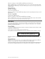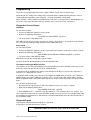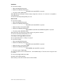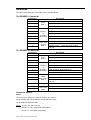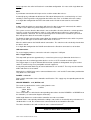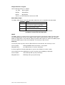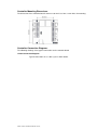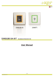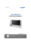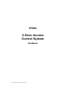
1
ST962
2-Door Access
Control System
Handbook
ST962 2-Door Controller Handbook convert
ST962 2-Door Access Control System
General Description
This system provides a stand-alone programmable access control system based on the SMART
Technologies Secure Card proximity card technology or on Wiegand output devices.
The system consists of a controller with relays to operate a single door or two independent doors.
The controller supports two input devices which can be Secure RFID readers, Wiegand output devices (reader, keypad etc.) or a combination of the two types.
The Secure Card RFID readers can be mounted up to 50 meters from the controller with a simple 3wire connection. The readers are fully potted and suitable for mounting outdoors. Tampering with
these readers will not compromise the systems security. The Secure Card Technology prevents cards
being duplicated, further enhancing the system security.
Programming the system is very simple and requires a Master Tag or Master PIN code to put the unit
into programming mode. In this mode tags or PINs can be added or deleted and relay operation configured. A jumper setting allows tags or PINs to be added automatically to both readers/keypads or to
allow each reader or keypad to have its own set of tags/PINs.
The optional Tag Simulator / Programming Unit, when used in conjunction with the Master tag, can be
used for deleting lost tags. It can also be used for adding tags.
Transactions are stored in the controller’s non-volatile memory with a date & time stamp. The data
logging software provided with the system allows a PC to set the controller’s date & time settings and
to download the transactions.
PC connection to the controller is connected to the PC via a USB port.
Note that both input devices must be of the same type - i.e. both keypads or both readers.
Wiegand Convention
The following convention has been used in this document relating to the colour of the LEDs in Wiegand devices.
It is assumed that the device has a single LED control line with the following states:
Pulled High -- RED LED on
Pulled Low -- GREEN LED on.
Wiegand devices must output 26 bit format
Normal Operation - Run State
The unit has three states Add Master, Programming and Run. The Run state is the normal operating
state of the unit and the operation depends on the Mode selected at installation time. The Add Master
and Programming states is explained in the next sections.
Secure Reader
Run State - Pulse Mode
In this state, the YELLOW lamp is always on and the GREEN and RED lamps are off.
Whenever a valid tag is read, the GREEN lamp will go on and the relay will operate, for the pre-set
Relay Pulse time.
If a card is not valid the RED lamp will go on for 1.5 seconds.
Run State - Toggle Mode.
On power-up, the YELLOW and RED lamps will be on and the relay will be off.
ST962 2-Door Controller Handbook convert
Whenever a valid tag is read the GREEN and RED lamps will change state.
While the GREEN lamp is on and the RED lamp is off, the relay is energised (the NO contact will be
closed). When the GREEN lamp is off and the RED lamp on, the relay is not energised (the NO contact will be open).
Wiegand Device
Run State - Pulse Mode
In this state, the RED lamp is on
Whenever a valid tag is read the GREEN lamp will go on and the relay will operate for the pre-set Relay Pulse time.
Run State - Toggle Mode.
On power-up the RED lamp is on.
Whenever a valid tag is read the RED and GREEN lamps will toggle.
While the GREEN lamp is on the relay is energised (the NO contact will be closed). When the RED
lamp is on, the relay is not energised (the NO contact will be open).
Add Master
The first tag or PIN read by the system when the controller is in the factory default state will become
the master for both input devices irrespective of the setting of the mode jumper. (This is why both input devices must be of same type.)
Secure Reader
If the RED and GREEN are flashing an alternate even pattern, it indicates that the memory is empty
and that there is no Master Tag.
In this state the first tag read will be stored as the Master Tag.
This tag will be the master for programming even if the second device on the controller is a keypad.
Store the Master Tag or PIN in a safe place. If it is lost
you will not be able to program the unit.
If the master tag/PIN is lost the controller will have to be reset and all user and transactions data will
be lost.
Wiegand Devices
When the unit is in the default factory state the Wiegand LED will toggle equally between RED and
GREEN at a rate of about 4 per second (each LED colour on for about 250mS).
In this state, the Master is the first tag presented to a reader or PIN entered on the keypad .This will
be the Master for all programming even if the second device on the controller is a secure reader.
ST962 2-Door Controller Handbook convert
Programming
To put the system to Programming state, read the Master Tag or enter the Master PIN.
Depending on the setting of the mode jumper, tags/PINs will be added or deleted from the current
reader/keypad or from both readers/keypads - see page 8 for Mode setting details.
When memory is full the RED lamp will light briefly each time a new tag or PIN is added. Multiple entries of the same tag or PIN will not waste memory space - the entry is only stored once.
Wiegand or Secure Reader
Add Mode
To select this function:
1. Present the MASTER TAG once to the reader.
2. Wait for the following LED pattern:
Long RED and short GREEN - repeated.
3. The unit is now in TAG ADD mode.
Now add new tags by presenting each tag to the reader. As each one is accepted the relay will operate. To return to normal operating mode present the MASTER TAG.
Delete mode
To select this function:
1. Present the MASTER TAG twice to the reader with a time between reads of less than 2 seconds.
2. Wait for the following LED pattern:
Short GREEN Short RED Short GREEN Long RED - repeated
3. The unit is now in TAG DELETE mode.
Now delete a tag by presenting that tag to the reader.
To return to normal operating mode present the MASTER TAG.
Time Adjust and Toggle Mode Selection
This function sets the relay operating time for a push-button input and a valid tag or PIN entry. It also
determines if the unit operates in PULSE or TOGGLE mode.
In PULSE mode the GREEN lamp and the relay will operate for the pre-set pulse time each time a
valid access is allowed by the system.
In TOGGLE mode a valid access will cause the GREEN and RED lamps to change state. While the
GREEN lamp is on and the RED lamp is off, the relay is energised (the NO contact will be closed).
When the GREEN lamp is off and the RED lamp on, the relay is not energised (the NO contact will be
open).
To select this function for tags:
1. Read the Master Tag three times with a time between reads of less than 2 seconds.
2. Now wait for following LED pattern:
Long GREEN Short RED - repeated
3. Each GREEN flash is 1 second of relay operation time. The maximum time is 25 seconds. Present a tag to the reader after the required number of flashes have occurred. To set toggle mode allow
the flashing to exceed 25 flashes after which the unit will automatically return to normal mode with relay in TOGGLE mode.
Wiegand Keypad
Only keypads that output 26 bit wiegand are supported.
If keypad has site code this must be set to 0.
PINS 00001-00009 are reserved - they cannot be used for PINs.
ST962 2-Door Controller Handbook convert
Add Mode
To select this function:
1. Enter the MASTER PIN and #.
2. Wait for the following LED pattern:
Long RED and short GREEN - repeated.
3. The unit is now in ADD mode.
Now add PINs by entering the number and pressing # after each one. As each one is accepted the
relay will operate.
To return to normal operating mode press 9#.
Delete mode
To select this function:
1. Enter the MASTER PIN and #.
2. Wait for the following LED pattern:
Long RED and short GREEN - repeated.
3. Now enter 2# to select Delete Mode
4. Wait for the following LED pattern:
Short GREEN short RED short GREEN long RED - repeated.
5. The unit is now in DELETE mode.
Now delete PINs by entering the number and pressing # after each one.
To return to normal operating mode press 9#.
Time Adjust and Toggle Mode Selection
For an explanation of these settings see page 4.
To select this function:
1. Enter the MASTER PIN and #.
2. Wait for the following LED pattern:
Long RED and short GREEN - repeated.
3. Now enter 3# to select Delete Mode
4. Wait for the following LED pattern:
Long GREEN and short RED - repeated.
5. The unit is now in TIME mode.
To set the relay time enter a value between 1 and 25 followed by #. This will set the relay pulse time
in seconds.
To select relay toggle mode enter 99#.
Any other value will be ignored.
After entering a value the unit will return to normal mode.
ST962 2-Door Controller Handbook convert
Installation
The tables below detail the connections to the controller board.
The READER 1 Connector
Connector 1
Description
1
COM (common)
Relay
Door 1
2
NC (normally closed)
3
NO (normally open)
4
+12V
5
6
7
Reader 1
or
Keypad 1
connections
8
11
DATA1 (Wiegand D1)
LED control for Wiegand Devices
0V
9
10
DATA0 (Secure Reader DATA) (Wiegand D0)
EXIT1 (normally open push button )
Switch Connections
Door 1
0V (for DOOR switch and Exit push button)
DOOR1 (status - switch closed when door
closed)
The READER 2 Connector
Connector 2
Description
1
COM (common)
Relay
Door 2
2
NC (normally closed)
3
NO (normally open)
4
+12V
5
6
7
Reader 2
Or
Keypad 1
connections
8
DATA0 (Secure Reader DATA) (Wiegand D0)
DATA1 (Wiegand D1)
LED control for Wiegand Devices
0V
9
EXIT2 (normally open push button ))
11
Switch
Connections
Door 2
12
Trigger
OP3
13
Controller
and reader
power
+12V
10
14
0V (for DOOR switch and Exit push button)
DOOR2 (status - switch closed when door
closed)
(open collector output)
0V
Connector Details
Relays
The relays have voltage free contacts and they are rated at:
5A @ 120VAC and 2.5A @ 240VAC for non-inductive loads
3A @ 28VDC for inductive loads.
Relay 1 operates the door strike for:
Reader 1 & 2 in a single door configuration
Reader 1 in a two door configuration
ST962 2-Door Controller Handbook convert
Relay 2 operates the strike for Reader 2 in a two door configuration. It is not used in single door configuration.
EXIT
A push button connected to this input can be used for remote door release.
A normally open pushbutton wired between Exit and 0V will operate the associated relay as if activated by a valid Tag and the relay operation time will be the same as the door strike time setting.
In a single door configuration the EXIT connection on the Reader 2 connector has no function.
DOOR
A door switch wired to these connections will detect if a door is opened. If connected, this switch is
used to reset the door relay and to complete an access transaction.
The system assumes that the door switch is not used until the first time it detects a switch operation.
Once the system has learned that a switch is used, it will only log a valid access transaction if a
switch operation is detected. This has the advantage that if a valid card is read but the person then
does not open the door, the transaction is ignored.
To disable the door switch function, power-down the controller and disconnect the switch. On powerup the system will again assume that the door switch is not used.
Wire the switch between the DOOR and 0V connections. The switch must be electrically closed when
the door is closed.
In a single door configuration the DOOR connection on the Reader 2 connector has no function.
USB Connection
To use the logging software, connect the unit to the computer’s USB port.
OP3 - Trigger Output
This output will operate for approximately 1 second every time a tag is allowed or denied access.
This output can be used to trigger other devices such as a CCTV recorder or switch a light.
The Trigger output is an open collector NPN transistor capable of sinking 50mA. It may be used to
switch an external relay or any compatible external equipment.
A relay with protection diode may be connected between +5V and OUT. The relay must be rated for
5VDC and draw less than 50mA.
Alternatively a 12VDC Relay can be connected between the +12V and OUT connections provided the
relay draws less than 50mA.
POWER: +12V & 0V
Power supply connections for the Controller and Readers. This supply may also provide power for the
door strikes.
SECURE READER: +12V, DATA0 & 0V
The reader is potted and has 3 wires exiting from the rear.
The wires are: Red
+12VDC
Yellow DATA
Black 0V
These connections are wired to the corresponding connections of either READER-1 or READER-2 on
the controller (see connection diagrams for details).
Cable length between a reader and the controller must not exceed 50m.
Shielded cable is not required provided the cabling is not used in an electrically noisy environment. If
shielded cable is used, the shield must be connected to 0V at the Controller connector.
2
The cable should be 3-core with a minimum cross section of 0.22 mm .
Solid core wire is NOT recommended
ST962 2-Door Controller Handbook convert
Wiegand Reader or Keypad
Connect Wiegand devices as follows:
+12 & 0V - Device power
DATA0
- Wiegand D0
DATA1
- Wiegand D1
If there is an LED control line connect it to LED
Mode (ABC) Jumper
The Mode (ABC) jumper selects the operation mode of the unit as detailed in the table below.
Position
A
B
C
Mode
2 doors each with 1 reader/keypad each device has different tags/PINs
2 doors each with 1 reader/keypad same data for both readers
1 door with 1 or 2 readers/keypads
These pins are connected directly to static sensitive electronics.
Avoid direct contact with the jumper pins.
RESET
The Mode Jumper is used to clear the system memory and reset to default settings. Remove power
and short both position A and C of the Mode Jumper. Now reconnect power, wait for the “first time
power-up” LED pattern as described in “Power-up” below. Now remove the short on the Mode jumper
and set the Mode jumper to the desired position. The memory is now cleared.
Power-up
On first time power-up of the unit the LEDs will flash to show that the units memory is clear:
Secure Reader
RED and GREEN alternate flashing - even pattern
Wiegand Device
the LED will flash an even on / off pattern
A master tag/PIN can now be added to the system as described in an earlier section.
Once a Master has been added to the system, on power-up the following is displayed:
Secure Reader
YELLOW lamp will stay on permanently.
Wiegand Device
RED lamp will stay on permanently
ST962 2-Door Controller Handbook convert
Controller Mounting Dimensions
The dimension of the controller board is 86 mm x 86 mm it has four 3.2 mm holes for mounting.
Controller Connection Diagrams
The following drawings show typical connections to the controller board.
1-Door Connection Diagram
Typical connections for a 1 door system shown below.
ST962 2-Door Controller Handbook convert
f
ST962 2-Door Controller Handbook convert
2-Door Connection Diagram
Typical connections for a 2 door system shown below.
ST962 2-Door Controller Handbook convert
Wiegand Connections
The drawing below shows typical connections for a Wiegand device.
Battery
The unit is powered by a PP3 9V battery. Undo the 2 screws at the back of the unit to gain access to
the battery.
Setting Tag Number
To set the tag number to be deleted or added:
1. Hold the On/Off button down.
2. Use the RIGHT ARROW key to move the cursor to the digit to be changed.
3. Use the UP ARROW key to change the number at the cursor.
4. Repeat the above until all the digits of the number are correct.
5. This number is stored in memory and the On/Off button may now be released.
Deleting Tags
The MASTER tag must be used to put the unit into the Delete mode.
Once in Delete mode:
1. Place the Tag Simulator close to the reader
2. Hold down the On/Off button and check the displayed number
3. Press the Send button
4. Once the tag or a group of tags have been deleted, read the Master Tag to return to the RUN
state.
Adding Tags
The MASTER tag must be used to put the unit into the Add mode.
Once in Add mode:
1. Place the Tag Simulator close to the reader
2. Hold down the On/Off button and check the displayed number
3. Press the Send button
4. Once the tag or a group of tags have been added, read the Master Tag to return to the RUN
state.
ST962 2-Door Controller Handbook convert
Logger Software (962-91)
The Windows based logging software is used to download transaction data from the controller and set
the unit’s date and time.
The software also allows names to be associated with tag numbers and the printing of reports.
Access Control is disabled when the unit is connected to the USB port of the
computer
Software Installation
The installation is in 2 parts
Logger Installation.
USB Driver installation
The software only support Windows 2000 or Windows XP .
Logger Installation
Insert the CD-ROM into the drive and log on to the drive.
At the prompt type SETUP and follow the instructions on the screen.
USB Driver Installation
For Microsoft Windows 2000 Desktop:
1. . When the USB cable is connected, a “ New Hardware” message appears.
After a brief interval, this will be replaced by the “ New Hardware Wizard” dialog. Click Next.
2. At the “ Hardware Device Drivers” dialog, select the “ Search for a suitable driver” option. Click
next.
ST962 2-Door Controller Handbook convert
3. At the “ Driver Files” dialog, select the “ Specify a location” check box. Click Next.
4. At the next dialog, click the Browse button to open the Windows Locate File dialog and select D:\ .
Click Open to accept the location, then OK at the original dialog
5. At the “ Installation” dialog, confirm that the wizard has located the file 962.inf . Click Next.
6. After a brief interval, the final Hardware Wizard dialog will confirm that the driver has been installed. Click Finish.
It will not be necessary to restart the system.
ST962 2-Door Controller Handbook convert
For Microsoft Windows XP:
The USB driver installation process is similar to that of Windows 2000, but requires fewer steps.
1. After the USB cable is connected, the initial Hardware Wizard dialog appears. Select “No not this
time” and click Next.
2. On the next screen select “ Install from a list of specific locations” option. Click Next.
3. At the next screen select “Search for the best driver in these locations and select “Select removable media” Now click Next.
ST962 2-Door Controller Handbook convert
4. At the warning screen click “Continue Anyway” .
5. The final dialog will indicate that the driver has been successfully installed. Click Finish.
It will not be necessary to restart the system.
Regardless of the versions of the operating system, the 962 system will appear in the Device Manager view (available from the System applet in the Control Panel) when the installation is complete.
The 962 System will appear as shown below. Take note of the Com port number as it will be required
when configuring the Log962 software.
The icon and name will be the same in all versions of Windows.
ST962 2-Door Controller Handbook convert
Software Operation
Double click on the 962 Logger icon to start the program.
The Menu bar is at the top of the screen.
The Status bar is at the bottom of the screen and shows the selected communications port on the left,
the communications status on the right.
The first time the program is run, it is necessary to set the communications port to be used by the logger. Select Configure|Settings and set the correct value.
The menu items are detailed below.
The program must be closed before unplugging the USB connector
Equipment Menu
The controller must be connected to the PC to use any of these functions.
Equipment|Collect Transactions
Select this to start the download of transactions. Once transactions are downloaded they are deleted
from the controller‘s memory.
Equipment|View Current Setup
Displays the reader ID codes, current date, current time, the number of transactions in the controller
and version number of the controller firmware.
Equipment|Set Time\Date
Displays the computer's Time and Date and also the values currently set in the controller’s time.
New values for the time and date can be set by entering required values into the Time and Date
fields. To set the values to the PC's time & date, click on [Set Device to PC]
To send the settings to the controller click on [OK ].
Equipment|Set Daylight Saving
The system allows for daylight saving to be applied to the time.
ST962 2-Door Controller Handbook convert
Check the box to enable daylight saving using the following rules
Summer Start Date: At 00:00 on this date the time is advanced to 01:00.
Winter Start Date:
At 01:00 on this date the time is retarded to 00:00.
Equipment|Set Reader IDs
Each reader can have its own 3 character ID code so as to identify the source of transactions.
The ID may be any combination of numbers and letters up to a maximum of 3 digits.
Configure Menu
Configure|Holders
Displays details of all holders in the database.
From the window select:
Add to enter a new holder's details.
Edit to modify an existing holder
Remove to delete a holder
Selecting either Add or Edit displays:
Required fields are Holder Name, Tag Number and Group.
Enter the Tag Number printed on the tag or card.
If a Group is not selected from the drop-down box, the holder will be assigned the first defined group
name.
Configure|Groups
Groups are used by Reports|Holders to group holders together.
Enter a name to define a Group.
ST962 2-Door Controller Handbook convert
Configure|Truncate Data
Select this function to reduce the size of the database and speed up reports.
There are three possible ways of truncating the database:
1. Date:- All records prior to and including the date entered are deleted.
2. Unregistered:- If the box is checked, all records where the holder is Unregistered (holder details
not entered), are deleted.
3. ID:- If the box is checked, all records of the entered unit ID code are deleted.
Click on [Truncate] to delete the selected records.
Configure|Settings
Registered Company Name
The name entered during installation and appearing on report headers. It may be modified.
Report Export Program
The Log 962 program uses an external program to format and display reports. By default it uses
NOTEPAD supplied with Windows.
The data format can be set to either Text or CSV (Comma Separated Variables).
To use any other program, enter it's path and filename.
Program Path
Path to the logger program. This is set by the installation program and should not require modification.
Communications Port
The USB port appears as a com port.
Select the com port attached to the USB port.
Reports Menu
Reports|Transactions
This report is a listing of all the transactions in the database. Before the report is compiled, you are
given the option to apply a number of filters to the data, which can narrow down the range of transactions. The filters may be any combination of Start Date, End Date and Unit ID.
To use a filter, click on the filter check box and enter the required value. Only records that match the
filter parameters appear in the report.
Click OK to create the report.
Reports|Holders List
Creates a report of Holders in the database.
Holders can be printed by group by checking the Group box and selecting a Group name from the
drop down list.
ST962 2-Door Controller Handbook convert