1
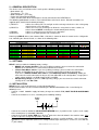
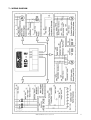
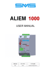
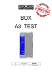
RED – E
USER MANUAL
2
03-07-13
REL.
DATE
T.M. Check and Approval
INDEX
1 - SAFETY ............................................................................................Page 3
2 - GENERAL DESCRIPTION ..............................................................Page 3
3 - INSTALLATION ...............................................................................Page 3
4 - SETTINGS ......................................................................................Page 4
5 - OPERATION ...................................................................................Page 4
6 - FINAL CHECK AND TEST ..............................................................Page 4
7 - WIRING DRAWING .........................................................................Page 6
8 - RED-E BOARD LAYOUT ................................................................Page 7
9 - TROUBLE SHOOTING ...................................................................Page 8
10 - TECHNICAL SPECIFICATIONS .....................................................Page 8
11 - DIMENSIONS AND WEIGHT ..........................................................Page 8
12 - CHECKS AND MAINTENANCE ......................................................Page 10
DECLARATION OF CONFORMITY ..................................................Page 11
RED-E USER MANUAL Release 2 date 03-07-2013
2
1 – SAFETY
SMS would like to thank you for choosing RED-E, the Automatic Rescue Device to the nearest
floor, in the most favourable run direction, for rope lifts and recommends to read carefully the
following indications for your safety.
Point
Memo
1
The device has a considerable weight. Lift it from the ground with
appropriate means to avoid problems with your health.
2
The device has a considerable weight. Be careful once it has been lifted
from the ground in supporting or fixing to a wall.
3
If the device is clearly damaged, missing parts, or the size of the device is
not correct for the lift, absolutely do NOT proceed with the installation.
4
The installation, control and maintenance of the device must be carried out
only by qualified personnel and only when the power supply is disconnected.
Improper installation can cause equipment malfunction, injury, or even
death. Carefully follow the safety directives.
Before making any connections, make sure that the control panel is not
supplied and that the IE switch the device is off. Avoid any kind of external
object enters the device as it can lead to the failure of the or hazardous
conditions at the time of connection to the mains.
Connect the ground of the device to the installation ground for the protection
against indirect contact, according to the safety directives. Properly protect
all connections to prevent accidental contact.
5
6
7
8
Description
The metallic case of the device has sharp edges. Handle it with care using
suitable gloves for the purpose.
Ø
To ensure the proper functioning of the device and in order to avoid risks of
fire, use cables of suitable section in function of the currents involved and
considering the cable length required for installation.
9
After put into operation and tested the device, remove the bridge made on
th
the 4 pole to ensure proper operation in case of opening of the main power
switch. Close the metal casing of the device to prevent accidental contact.
10
The device is battery operated, not normally provided by SMS. Be sure to
use batteries appropriate to the device and to the charging current indicated
to avoid the risk of explosion due to the release of hydrogen.
Do not reverse the polarity of the batteries or short circuit.
Consult the documentation provided by the battery manufacturer.
The examples and diagrams in this manual are included only for illustrative purposes. The
contents of this manual are subject to change without notice.
In no event will accept the liability for damages, indirect or consequential damages
resulting from the use or application of the device.
RED-E USER MANUAL Release 2 date 03-07-2013
3
2 – GENERAL DESCRIPTION
The device is fit in a metal box and it’s made up of the following components:
- Main Switch (IE)
- Transformers (T1 – T2)
- Motor Contactors (TP1–TP2)
- Power and Control Board (REDE)
- Cables for connection to the control panel, already connected to the REDE Board.
The following option boards can be used, to add functions to the basic device. Related instructions are
supplied apart, attached to the board packaging.
1) REOPLC:
It drives the retiring cam, the car light and the exchange circuit to use the existing stop
switch also for rescue operation.
It drives the necessary exchanges to divide the safety chain in more sections, to
transfer them to RED-E, insulating the related control panel circuitry.
It drives a second car access during rescue operation.
It drives a DC door operator and a retiring cam.
2) REOPTS:
3) REODA:
4) REOPDC:
Powering up RED-E device, from software R05, a led code is shown for about 5 seconds on the 3 diagnostic
leds, indicating the detected cards, as shown in the following table :
Possible mounting combinations of RED-E optional boards
PASSIVE BOARDS
REOPTS
REOPLC
Always possible
Always possible
Alone or with REOPTS
Alone or with REOPTS
Always possible
Always possible
Always possible
REODA
ACTIVE BOARDS (Serial communication)
REOPDC n.1
REOPDC n.2
OK
NO
NO
YES
YES
YES
SI
YES
YES
NO
YES
YES
YES
NO
NO
YES
NO
YES
NO
NO
YES
NO
YES
NO
NO
YES
Alone or with REOPTS
NO
Alone or with REOPTS
Alone or with REOPTS
YES
NO
Always possible
Alone or with REOPTS
YES
Always possible
Alone or with REOPTS
YES
Always possible
Alone or with REOPTS
NO
RED-E LEDs
NO
3 – SETTINGS
RED-E is delivered with the following factory settings:
• BRAKE coil voltage 48/60Vdc: if you need a different voltage, you must move the connection
BRAKE on the transformer T1, from terminal 70 to the desired one.
• 3-Phase Door Motor 125Vac: If you need a different voltage, you must move the connections
DOOR1 and DOOR2 on the transformers T1 and T2, from terminal 125 to the desired one.
If you have a SINGLE:PHASE door motor or a 3-PHASE door motor controlled by VVVF, you
must move the female connector existing on 3P, from 3P to VF. In this configuration, a single-phase
supply voltage 230Vac is available between MP1 and MP2.
• AC Operating voltage: if you have a DC Operating voltage, you must move the female connector
existing on AC, from AC to DC.
4 – INSTALLATION
RED-E can be easily “wall-mounted”, near the lift control panel.
Electrical connections must be carried out following the WIRING DIAGRAM at Par.7, considering the
following issues:
- Connect 1~230V 50/60Hz supply for battery charger to terminals F-N (LIGHT BLUE-BLACK/BROWN
wires).
- Connect the 4 batteries in series, according to the following drawing:
BLACK
WIRE
RED
WIRE
-
-
+ -
+ -
+ -
+
Connect the terminals L1-L2-L3 (BLACK-GRAY-BROWN wires) in parallel to the 3~phase main supply
of the control panel (3~230/400V 50/60Hz).
Connect the terminals S1-S2 (RED wires) to the 4th pole of the General Switch in the machine room. If the
4th pole is open the emergency operation is disabled.
This input can be used also to disable the emergency operation in specific conditions, such as inspection
operation o firemen operation (connect free voltage contacts open during these services in series with the
th
4 pole switch).
RED-E USER MANUAL Release 2 date 03-07-2013
4
-
-
-
-
Connect the terminals U-V-W-PE (BLACK + YELLOW/GREEN wires) to the motor (for 2-speed motor, to
the high speed winding), in parallel to the existing connection.
Cut off the brake coil supply, connecting the wires coming from control panel to terminals FQ+–FQ(PURPLE/BLACK wires) and the brake coil to terminals F+–F- (PURPLE wires).
Respect the polarities.
Connect door motor as follows:
1. 3-PHASE A.C. DOOR MOTOR (DIRECT OPERATION)
Cut off the door motor supply, connecting the wires coming from control panel to terminals MPQ1MPQ2-MPQ3 (BLACK/WHITE wires) and the door motor to terminals MP1-MP2-MP3 (WHITE wires).
2. DOOR MOTOR A.C. SINGLE PHASE OR A.C. 3-PHASE CONTROLLED BY VVVF
Move the ‘key’ connector connected to 3P on VF
Cut off the door motor supply, connecting the wires coming from control panel to terminals MPQ1MPQ2 (BLACK/WHITE wires) and the supply to the motor or to the VVVF drive to the terminals MP1MP2 (WHITE wires). Connect in parallel to the door drive commands the following terminals:
MP3 (WHITE wire) to the command common, MP4 (WHITE/RED wire) to the door opening command
and MP5 (WHITE/GREEN wire) to the door closing command.
Cut off the safety chain start, connecting the wire coming from the shaft to terminal IS (BLUE wire) and
the wire coming from the control panel to terminal ISQ (BLUE/BLACK wire).
Cut off the safety chain end, connecting the wire coming from the shaft to terminal FS (ORANGE wire)
and the wire coming from the control panel to terminal FSQ (ORANGE/BLACK wire).
Connect the terminal M- (BLACK wire) to the control panel earth.
Connect the terminals Z1-Z2 (RED wires) to the emergency stop switch N.C. contact.
RED-E doesn’t supply a specific output signal for “Rescue operation running”. If necessary, connect the
light signal to the secondary winding 0-24 of transformer T1 or T2 where a 24Vac voltage is present
during all the rescue operation.
5 – OPERATION
RED-E starts when a mains power failure occurs (even if a single phase fails), with the 4th pole switch
closed.
After 4-5 seconds, the red Led B lights on, the emergency cycle starts and it’s brought to end even if the
main supply is back in the meantime.
The circuits of the control panel which control brake, safety chain, door motor, etc. (connections with doublecolor wires) are cut off, then the auxiliary inverter supplies the transformers T1 and T2.
The emergency cycle goes on in a different way according to car position:
1) CAR AT FLOOR. RED-E commands the door opening. After the door opening time, adjustable with
trimmer P, has elapsed, the emergency turns off and RED-E is ready to start a new emergency cycle.
2) CAR NOT ALIGNED WITH A FLOOR. RED-E controls the safety chain status. If the safety chain is open,
it commands the door closing for 20 seconds maximum. When the safety chain is closed, RED-E makes
the door closing command to go off and makes the contactors TP1 and TP2 to energize.
Then, RED-E switches on the power inverter which controls the car run.
It makes 2 tests in order to choose the most favourable run direction, then the car runs and reaches the
first floor in that direction; after the stop switch delay (adjustable with trimmer R), the car stops, the TP1
and TP2 contactors de-energize and the doors open.
At the end of the door opening time, RED-E turns off and becomes ready for a new emergency cycle.
6 – FINAL CHECK AND TEST
Once that all the connection has been done as shown in the diagram, with the Main Power Switch open,
check the battery charge status:
- Remove temporarily the CN8 connector and check the voltage of the 4 battery series voltage:
it must be higher than 48V and lower than 54V.
Switch on the Main Power Switch and check that the lift is working properly.
Check in particular the operation when the contacts of the safety chain open.
You can now test the emergency operation, following the instruction hereunder:
- Switch off the Line 1~230V 50Hz, by opening the relative Switch.
- Switch off the main power, opening the Main Power Switch, with car aligned with none floor.
- Make a bridge between terminals S1-S2, because if the 4th pole is open, the lift cannot perform the
emergency operation.
After a few seconds, the emergency operations starts, and it is carried out in the way illustrated in the
previous paragraph OPERATION.
RED-E USER MANUAL Release 2 date 03-07-2013
5
6.1 – ADJUSTMENTS
Usually RED-E doesn’t need any particular adjustment, however, in order to fit in every kind of lift system,
the following adjustments are available:
Trimmer P : Door opening time (from 0 to 31 seconds)
Trimmer R : Stop switch delay (from 0 to 5 seconds)
Trimmer V : Gear Motor output voltage (from 18 to 36V)
Trimmer F : Gear Motor output frequency (from 1 to 10 Hz)
IMPORTANT:
The motor torque increases if you increase the motor voltage (V) and if you decrease the motor
frequency (F). This operation though, makes the current absorbed by the motor to increase,
and it can cause the overload protection to trip.
Usually, the factory settings (V = 50% and F = 50%) assure a good operation with any kind of
motor.
6.2 – INSULATION TEST INSTRUCTIONS
1. Place the switch IE of RED-E in OFF position.
2. Disconnect the terminal M- (black wire) from the control panel.
3. In the same conditions you test the insulation of the different circuits of the control panel, test the
insulation of the circuits of RED-E, towards earth and towards the other circuits, on the following
terminals:
• A1
• 125
on the TP1 contactor
both on T1 and T2 transformer
• 220 both on T1 and T2 transformer
• F
1~230Vac battery-charger supply
• Red/Black wires of the battery series (0V, 48V)
RED-E USER MANUAL Release 2 date 03-07-2013
6
7 – WIRING DIAGRAM
RED-E USER MANUAL Release 2 date 03-07-2013
7
8 –RED-E BOARD LAYOUT
ST
ST, RS : 3-phases
Main Power Monitor
RS
CB
UP
4P
CH
AP
BK
VP
CB : Battery Charger ON
IB : Inverted batteries
KE
CC
IB
OP
BC
WP
UP,VP,WP : 3-Phase Output
Voltage Monitor
SP4
SP3
SP2
SP1
ZF
CT
RED-E BOARD
P : Door Opening Delay,
from 0,1 to 31 seconds
ON
R : Stop Delay,
from 0 to 5 seconds
A,B,C : Monitoring
Leds
A
Input
B
:
Output :
SW1
1 2 3 4
R
P
F
V
F : Motor Output Frequency
from 1 to 10 Hz
V : Motor Output Voltage
from 18 to 36 Vac
C
th
ST-RS: 3-phases main power ; ZF: Stop switch input (Z1-Z2); 4P: 4 pole input;
CT: Contactors control input .
KE: Safety chain switch; CC: Contactors command; CH: Door closing; AP: Door opening; BK: Motor brake;
BC: Contactor energy saving bypass: OP: Optional Output (2 switching contacts on terminal boards M1 and M2)
SETTINGS
Dip Switch SW1
1
2
3
4
Description
OFF : N.C. STOP SWITCH
OFF : NORMAL DOOR CLOSING
N.U.
N.U
Solder points settings
(Function of clean contacts NO-NC on terminals M1 and M2 – Only one solder point must be closed)
ON : N.O. STOP SWITCH.
ON : FORCED DOOR CLOSING
N.U.
N.U.
Solder points
SP1
SP2
SP3
SP4
Led A
Closed : KE1 (Rescue operation active)
Closed : CC ( Motor contactors active)
Closed : CH (Door closing)
Closed : AP (Door opening)
Led B
Led C
Default setting.
-
Monitor
Description
RED-E not ready (4° Pole open)
RED-E ready to rescue operation
Rescue operation running
Rescue operation carried off
Auxiliary Inverter Overcurrent
Power Inverter Overcurrent
Battery Voltage too low or too high
Missed starting
Maximum operating time expired
Regenerated current towards batteries
Motor not connected
Contactor contacts always closed
RED-E USER MANUAL Release 2 date 03-07-2013
Notes
= Led OFF
= Led ON
= Led FLASHING
8
9 – TROUBLESHOOTING
1) The car doors work properly when supplied by mains power, while they work in the opposite way when
supplied by RED-E:
Exchange MP1 with MP2 and exchange MP1Q with MP2Q
2) When the emergency operation starts, the over current protection of the auxiliary inverter trips (Led A
flashes):
Check the connections between RED-E and control panel and try to disconnect all the circuits and
connect them again one at a time, when you find out the connection which makes the auxiliary inverter
to trip, check carefully the corresponding circuit.
3) When RED-E drives the motor, the over current protection of the power inverter trips (Led B flashes):
Check that RED-E is compatible with motor power which has to be controlled. Check that the
terminals U, V e W are connected to the motor high speed winding only.
Decrease the power inverter output voltage (turning the trimmer V anti-clockwise) and increase the
output frequency (turning the trimmer F clockwise).
4) When RED-E drives the motor, the Leds UP, VP, WP flashes, but the motor doesn’t rotate:
Increase the power inverter output voltage, turning the trimmer V clockwise.
Decrease the power inverter output frequency, turning the trimmer F anti-clockwise.
5) The run direction selection is wrong, for example RED-E chooses the unfavourable direction and it is not
able to drive the motor:
Try to decrease the power inverter output frequency, turning the trimmer F anti-clockwise.
6) The emergency run is carried on with “jogging” operation:
This is not a faulty operation, this type of operation is done for safety reason, in order to avoid that in
lifts with highly reversible gears the car can take dangerous speed without any control.
7) When the car reaches the floor, it doesn’t stop at the correct level:
if the car oversteps the floor level, decrease the stop delay, turning anti-clockwise the trimmer R.
if the car stops before reaching the floor level, increase the stop delay, turning clockwise the trimmer R.
10 – TECHNICAL SPECIFICATIONS
RED-E is equipped with a single board, which includes the following functions:
Battery-charger, which can supply a 200mA current, with a 54Vdc voltage, useful to charge n° 4
batteries 12V in series, up to 12Ah.
The supply voltage for the battery-charger must be 230Vac 50/60Hz +/-10%
• 3-Phase auxiliary inverter 3x36Vac 15A, which can supply the 2 transformers 200VA.
The maximum output power is 600VA
• 3-Phase power inverter PWM, with adjustable voltage from 18 to 36Vac.
SIZE 1 : Maximum output current 18A. It is suitable to drive motors up to 18A nominal current.
SIZE 2 : Maximum output current 25A. It is suitable to drive motors up to 25A nominal current.
RED-E is protected against overload, polarity inversion of the batteries and output short-circuit, both for the
auxiliary sections and the power section.
RED-E is not protected against over voltage due to wrong connections on the motor output, or over
supply (battery voltage higher than 60Vdc).
•
11 – DIMENSIONS AND WEIGHTS
DEVICE
Height
(mm)
Width
(mm)
Depth
(mm)
Weight (kg)
without batteries
Weight (kg)
with batteries
RED-E
SIZE 1
360
360
210
18
28
RED-E
SIZE 2
360
360
210
19
29
RED-E USER MANUAL Release 2 date 03-07-2013
9
11 – CHECKS AND MAINTENANCE
In any case of electric check or modification,
be sure to open IE switch and
to disconnect any mains power.
Verify periodically what follows, starting with mains voltage present :
1) Battery voltage. If battery voltage is at correct level, RED-E board have not to signal an alarm
condition (see page 8).
2) Green leds of battery chargers have to be lighted ON.
3) Switching OFF the mains power with 4th pole open, the rescue operation have NOT to start.
4) Closing the 4th pole with a bridge, rescue operation have to start and finish properly, please follow
indications at point 6 – FINAL CHECK AND TEST. If rescue operation doesn’t properly end and
MIAE board indicates ‘Battery voltage too low’, batteries may have to be replaced.
th
Remove the bridge done on the 4 pole .
5) After some years of work, typically 4, replace the batteries and apply a label indicating the date of
replacement.
RED-E USER MANUAL Release 2 date 03-07-2013
10
DECLARATION OF CONFORMITY
Manifacturer:
SMS SISTEMI E MICROSISTEMI s.r.l.
Address:
Via Guido Rossa, 46/48/50 – 40056 Crespellano (BO) - Italy
Product:
EMERGENCY RESCUE DEVICE
RED – E
Model/Type:
The above mentioned products are in conformity to the requirements of the following
European Directives:
95/16/CE
‘LIFTS’
To evaluate the conformity, the following STANDARDS have been taken into
consideration:
EN 81.1: 1998 + Amendments A1,A2,A3
DATE: 12-04-2012
SMS SISTEMI E MICROSISTEMI s.r.l.
____________________________
Eng. VITTORIO MAZZONI
MANAGING DIRECTOR
For further information and advice please contact :
SMS SISTEMI e MICROSISTEMI s.r.l. (Gruppo SASSI HOLDING)
Cap. Soc. 260.000 i.v.
Via Guido Rossa, 46/48/50 40056 Crespellano BO
R.E.A 272354 CF - Reg. Imprese Bo 03190050371 P.IVA IT 00601981202
Tel. : +39 051 969037 Fax : +39 051 969303 Technical Service: +39 051 6720710
Web : www.sms.bo.it E-mail : [email protected]
RED-E USER MANUAL Release 2 date 03-07-2013
11