1
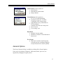
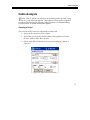
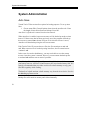
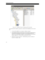
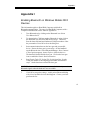
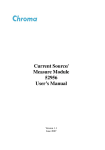
Version 4.1
Softree Technical Systems Inc.
Document Version 4.1 - 10/24/2005
The software described in this document is furnished under a license agreement or non-disclosure agreement.
The software may be used or copied only in accordance with the terms of that agreement. No part of this
manual may be reproduced or transmitted in any form or by any means, electronic or mechanical, including
photocopying and recording, for any purpose other than the purchaser's personal use without the written
permission of Softree Technical Systems Inc.
No warranty is expressed or implied as to the documented function or performance of the software described.
The user of the software is expected to make the final evaluation of the results in the context of his own
application.
Copyright Softree Technical Systems Inc. 2004. All rights reserved.
Trade Marks
Criterion and LaserSoft are registered trademarks of Laser Technology, Inc.
Microsoft Windows CE and Microsoft ActiveSync are trademarks of Microsoft Corporation
RoadEng and Terrain Tools are registered trademarks of Softree Technical Systems Inc.
#8 - 650 Clyde Avenue
West Vancouver, BC
Canada, V7T 1E2
Table of Contents
Table of Contents
TABLE OF CONTENTS..........................................................................................3
OVERVIEW ..........................................................................................................5
INSTALLATION AND REGISTRATION ...................................................................8
Installing from the CD....................................................................................9
Installing from the Web................................................................................10
Installation Default Directory...................................................................11
Registering for a Password...........................................................................12
GETTING STARTED ...........................................................................................13
Conventions..................................................................................................13
Menu Options...............................................................................................13
General Options............................................................................................15
Status Bar Display....................................................................................16
CREATING SCREEN LAYOUTS ...........................................................................17
Add, remove or to change the position of columns......................................18
Change the data entry order (Tab / Enter Sequence)....................................19
Column Descriptions....................................................................................20
ENTERING SURVEY NOTES ...............................................................................23
Moving Around ............................................................................................26
Side Shot Data Entry ....................................................................................27
Extended Side Shot Edit Dialog...............................................................27
Setup for text entry or SSL/SSR with optional extended entry................29
Setup for SSL/SSR extended entry always ..............................................30
DISPLAYING MAPS AND PROFILES ...................................................................31
Map View.....................................................................................................31
Making the Map visible............................................................................31
Displaying Background Traverses / Images.................................................33
To add or remove background traverses: .................................................34
To add or remove background images: ....................................................35
Zoom to Background Item .......................................................................36
Backgrounds are persistent.......................................................................36
Profile View .................................................................................................36
Making the Profile visible ........................................................................36
SURVEY ADJUSTMENTS ....................................................................................38
3
Table of Contents
Absolute Coordinates ...................................................................................38
Closing a Traverse........................................................................................39
Joining Traverses..........................................................................................41
Join using the Notes view only.................................................................42
Join using the Map view...........................................................................43
Map Coordinate Adjustments.......................................................................45
Geo-referencing a Bitmap Image .............................................................45
Geo-referencing a traverse to an Image....................................................46
WORKING WITH A LASER GUN .........................................................................48
Connection Settings......................................................................................48
Establishing a Connection ............................................................................48
Serial Input Dialog .......................................................................................50
Shot Types....................................................................................................51
Inserting a Shot.............................................................................................52
CABLE ANALYSIS .............................................................................................53
Creating a D-line. .....................................................................................53
Modifying Spar Positions using the Stylus. .............................................55
SYSTEM ADMINISTRATION ...............................................................................56
Auto Save .....................................................................................................56
Recovering Auto Saved Traverse Files ........................................................57
Opening Terrain CE Files in RoadEng or Terrain Tools - Survey...............59
Backing up Data ...........................................................................................59
APPENDIX I .......................................................................................................61
Enabling Bluetooth on Windows Mobile 2003 Devices ..............................61
APPENDIX II......................................................................................................63
SocketTM Bluetooth Card (Compact Flash)................................................63
4
Overview
Overview
T
errain Tools CE gives you the flexibility of entering field notes on your
Mobile Device (Pocket PC) in the field.
The Traverse screen (Figure 1.0) is used to enter field notes. It operates like a
spreadsheet, allowing entry or editing of raw data (bearings, distances etc.).
Figure 1.0: Terrain Tools CE
Traverse Notes
The screen can be divided into two (2) areas. The top area is the note entry area
and the bottom is an optional graphics area. The graphics are displayed either as
a plan or profile view of the traverse. The slider bar between the two areas allows
you control over the size of each view.
5
Overview
The Map can include one or more traverses. The traverses can be added or
removed from the map. The position of the current station in the traverse notes is
tracked in the map view area. Traverses can be closed, shifted or joined to other
traverses. Closing error and area is calculated and reported.
Note Entry Area
Slider Bar
Plan/Profile
(Graphic) Area
Menus
Figure 1.1: Terrain Tools CE View Area
The display area can also be toggled to display profiles and cable deflection lines
as shown in Figure 1.2.
6
Overview
Note entry area
Profile window
3rd point deflection
Ground line
Figure 1.2: Profile with a Deflection Line
7
Installation and Registration
Installation and Registration
B
efore Terrain Tools CE can be installed on your Mobile Device,
communication between your handheld and your desktop or laptop computer
needs to be established. You must be able to copy or move files back and forth
between the two computers. Files created on your desktop or laptop computer
may need to be copied by using Microsoft Active Sync or similar software so that
they can be accessed on your mobile device. We recommend following the setup
protocol enclosed with your Mobile Device.
When your Mobile Device is connected to your desktop, either by cable, cradle or
infrared, it will be displayed in Window Explorer as shown in Figure 2.0
Figure 2.0: Mobile Device Displayed in Windows Explorer on Desktop
8
Installation and Registration
Terrain Tools CE can be installed from the enclosed CD or downloaded from the
Softree web-siteweb site. http://www.softree.com/support/down1.htm
Supported hardware platforms:
Windows Mobile 2003 / Pocket PC 2002
Juniper Allegro CX
Juniper Allegro CE.Net / CE 3.0
TDS Ranger CE 3.0
TDS Ranger CE.Net
TDS Recon WinCE 3.0 (older model)
Trimble GeoExplorer CE.Net
DAP Microflex CE8640
An up-to-date list of models and platforms is available from the web-siteweb site.
Installing from the CD
1.
Insert the CD into the CD ROM drive on either your laptop or desktop
computer. Under Forest Engineering Software, select Handheld
Solutions.
Figure 2.1: CD Options
9
Installation and Registration
The Terrain Tools CE welcome screen appears with a list of supported hardware
platforms as shown in Figure 2.2.
Figure 2.2: CD Install Screen
2.
Attach your Mobile Device to your desktop PC and select the name and
platform of your Mobile Device. The software will detect your handheld
and install the software.
3.
Once the install is complete the TToolsCE icon
displayed on your Mobile Device.
will be
Installing from the Web
10
1.
Go to www.softree.com Select Support | Software Updates. Select
Terrain Tools CE. A list of supported handheld devices is displayed.
2.
Select and download the file adjacent to the name and platform of your
mobile device. Save the installation file (eg. TerrainToolsCE-
Installation and Registration
PPC2002.exe ) to the Tempa Directory folder on your desktop computer
system.
We recommend saving a copy of the installation file on your desktop in case reinstallation of the program is required.
3.
Connect your handheld device to the desktop computer (Active Sync
connection).
4.
On your desktop, double click on the executable installation file (e.g.
TerrainToolsCE-PPC2002.exe ) to begin the install process. The
install should take only a few seconds to complete.
5.
The TToolsCE icon
is now displayed on your Mobile Device.
A shortcut titled TToolsCE will appear on the Start menu under
Programs. Tapping either of these will start the Terrain Tools CE
program.
Note: It is useful to check the Softree website from time to time to ensure that your
software is up to date. Free maintenance upgrades are available.
Installation Default Directory
Two new folders are created when Terrain Tools CE is installed on your
handheld device.
\Mobile Device\My Device\Program Files\Softree\Terrain Tools CE contains the Terrain Tools CE executable (.exe) and wave files (.wav) for
sound alerts.
11
Installation and Registration
\Mobile Device\My Device\My Documents\Softree - contains the default
screen layout, ground types, and other program files.
Registering for a Password
Terrain Tools CE is password protected. Without a password the program
operates in demonstration mode. In demo mode Saving is disabled
The first time the program is opened the machine ID is written to the
SoftreePW.ini file and the program executes in demonstration mode.
1.
To Register your handheld, open TTools CE. A warning appears
Terrain Tools CE has not been registered .
2.
Go to C:\Mobile Device\My Device\My Documents\Softree. Email the
SoftreePW.ini with your name and company name to
[email protected]
3.
A new SoftreePW.ini file containing the password will be emailed back.
Copy and paste SoftreePW.ini into
C:\Mobile Device\My Device\My Documents\Softree. Say Yes to
over-writing the existing file.
Some firewalls block .ini files sent over the internet. If you have such a firewall,
copy the SoftreePW.ini to a temp directory on your desktop, rename the file to
SoftreePW.txt and email to [email protected] The process will have to be
reversed when you receive the .txt file back from Softree
4.
To activate the password close and re-open the program using File | Exit.
To verify that the program is no longer in demo mode, select
Help | About. It should state in full function mode.
POCKET PC WARNING
File | Exit closes Terrain Tools CE and will prompt you to save your changes. The
standard Microsoft X in the top right corner will minimize the application. The
changes , you will NOT be prompted to saved and the program will continue to run
as a background process.
12
Getting Started
Getting Started
T
his section of the manual explorers the functionality of Terrain Tools CE.
The information is general in nature and does not refer to any specific
Mobile Device. It is assumed that you are familiar with the general operations of
your handheld.
Conventions
The following conventions are used throughout the manual:
Menu functions are delimited by a line
. File Open means to Tap on File
in the menu bar and then tap Open from the pop up menu.
File | Exit will close the program and prompt you to save changes.
On Pocket PC devices the standard Microsoft X in the top right corner
minimizes the application. It does NOT close the program. Changes are NOT
saved.
Checkboxes, dialog boxes, column headings, and button names are italicized.
File names, path names and text to be typed in are in bold.
Menu Options
Terrain Tools CE has 6 main menus:
File
Edit
Station
Coords
Help
Escape
13
Getting Started
File Menu allows the user to:
Open a new or an existing traverse
Save a traverse file
Save or retrieve a screen layout.
Save a traverse file
Open or close the serial port for
connecting to a laser gun
List the name of the lastOpen recently
viewed
traverses
Exit the program
Edit Menu provides options to:
Turn on the status bar to identify traverse
and station
Enter in survey information such a date,
crew etc.
Set units (metric or imperial), decimals
and auto-save options.
Set display columns and tab order.
Set plan or profile scales.
Add or remove traverses or image files to
the plan display.
Set spar positions for d-line analysis.
Zoom in and out.
Toggle between plan and profile views.
14
Getting Started
Station Menu provides options to:
Delete shot(s)
Insert Shot at current station
Jump to Station
Coords Menu provides options to :
To view or set absolutemodify
coordinates using | Set / Get XYZ
Coordinates of the current station
Adjust Reduce survey information to
XYZ coordinates
Calculate Area and view closing error
Close Traverse
View closing error
Help Menu
Identifies Version number
Identifies if software is in full function or
demo mode
Esc (Escape)
This menu is similar to the Escape key
will undo previous coordinate changeon
a keyboard (not in the virtual keyboard).
General Options
The General Options Dialog is available by clicking Edit | General Options.
Units can be set to Metric or Imperial. Other units (chains, paces etc.) are
supported by changing the registry entries.
15
Getting Started
The Decimals for Reporting fields allow you to set the number of significant
figures for display of various computed values.
Pressing the Save as Default button will cause all the available units options to be
saved in the registry and used as defaults for new files.
Status Bar Display
The Status Bar can be shown or hidden by tapping Edit | Status Bar.
The left-hand side of the status bar displays the filename of the current notes.
The middle field displays the name of the background traverse when the current
point is on a background traverse. This field will be blank when the current point
is on the current traverse.
The right-most field displays the station of the current point, which can be either
the current traverse station or a background traverse station.
16
Creating Screen Layouts
Creating Screen Layouts
I
n Terrain Tools CE, the traverse screen is fully user configurable. Column
positions, format and sequence of entry can be user controlled. A variety of
angle and distance formats are available e.g. vertical angles, slope %, zenith
angle or inclination. Customized screen layout files (*.slt) can be saved and
quickly recalled to accommodate different surveying methods.
1. 1.
Tap the Terrain Tools CE icon to open the program. Select File |
New. A new Traverse document appears.
Figure 4.0: New Traverse Document
The screen layout and options visible have been read from the Normal.slt screen
layout file. Layout files are useful for personalizing the Terrain Tools CE screen.
17
Creating Screen Layouts
Window options such as scales, columns, tab/enter sequencedata entry order etc.
can be setup and saved in a layout file for future use. To modify the The default
screen layout screen for a new traverse, is update Normal.slt
There are two steps in customizing athe traverse entry screen. The first step is to
identify the columns and the order of entrydisplay. The second step is to
determine the order of data entry (tab/enter sequence). See Table 4.2 for a
descriptive list of available columns.
Add, remove or to change the position of columns.
2. 1.
Select the Edit | Entry Options menu, then select the | Columns
tab. Press the Add/Remove button. There are two tabs Available and
Selected. The Available tab lists all columns available. The names in
bold indicate they have been selected and are displayed on the Selected
list. See Figure 4.1
Figure 4.1: Column Setup
18
Creating Screen Layouts
2.3. To move a column item from the Available list to the Selected list
highlight the item and press the Add button. The new item now appears
at the bottom of the Selected list.
3.4. To change the column order in the Selected List, highlight the item you
want to move then select either the shift up or shift down button until the
item is in the correct position. To remove a column from the Selected list
highlight the column you would like to remove and press the Remove
button. Press OK to return to the main screen.
Note: You can change position and width of notes columns by tapping and dragging
in the column heading area of the main screen.
Change the data entry order (Tab / Enter Sequence)
to speed up note entry.
5. 1.
Select the Edit | Entry Options menu, then select the| Order tab.
Tap Tab /Enter Sequence. A dialog box similar to Column Display
appears. Use the procedure above to Add, Remove and shift column items
in the Selected list. Press OK to return to the main screen.
Now that your screen is configured the way you want it, save the screen layout to
a file:
6. 2.
Select File Save Traverse Screen Layout to save the new
customizations along with the rest of the Traverse Entry Options. The
screen layout will be saved with the given name and the extension
*.SLT.
If you have RoadEng or Terrain Tools Survey Version 4 on your desktop, you can
copy over your existing layouts (*.SLT) to your Mobile Device.
19
Creating Screen Layouts
Column Descriptions
Station
Station Column is automatically calculated and can be
shown asshows cumulative horizontal distances. It is
based on survey notes data entered at lower stations. You
can notcannot directly edit this cell (except for the
starting point of a traverse). If you have Station
Equations, see Field Ref.
Total SD
The Total SD (cumulative slope distance) Column is
automatically calculated. It is based on survey notes data
entered at lower stations. You cannot directly edit this
cell (except for the starting point of a traverse).You can
not directly edit this cell. You can define the starting
station by double tapping on this column to open the
Survey Information Dialog.
Index
The Station Index Column is automatically calculated.
The Station Index consists of 2 parts, a prefix and an
index. The prefix and a start index can be set in Edit |
Survey Information. The index is automatically
incremented at each station. You cannot directly edit this
cell (except for the starting point of a traverse).
Type
Identifies the Type of shot:
FS- foreshot
RS- radial side shot
IFS- intermediate foreshot
Foreshot
20
The Fore Azimuth measures the absolute (compass) angle to
the next station. It is common to measure this angle in
decimal degrees (0-360). However, it is also possible to
enter this angle in other formats such as degrees, minutes
and seconds
Creating Screen Layouts
Backshot
The Back Azimuth measures the absolute (compass) angle to
the previous station. The angle can be measured in decimal
degrees (0-360) or other formats such as degrees, minutes
and seconds (see Edit | Entry Options, Format tab).
H. Dist
Horizontal Distance for the shot. If a value is entered in the
HD field, the slope distance will be calculated and displayed
in gray in the SD column.
S.Dist.
Slope Distance for the shot. If a value is entered in the SD
field, the horizontal distance will be calculated and
displayed in gray in the HD column.
Slope
This column contains the Slope percentbetween stations. If
nothing is entered, the slope % will default to 0horizontal.
The format of the slope is commonly set to %, however,
other formats can be used (see Edit | Entry Options, Format
tab).
Double tapping on this column will popup the Height of
Instrument / Target Dialog; this is valuable if you do not
wish to display the HI and HT columns.
Inst. Height
( HI)
Height of Instrument column contains the instrument height.
The default is 0.
Target Height
(HT)
Height of Target column contains the target height. The
default is 0.
SSL / SSR
Stores the Left (Right) perpendicular side slope shot data
an optional pair of short surveys defining the cross section.
The % side slope of the cross section (or elevation
difference perpendicular to the traversed line ( P-line) line
is displayed in this cell. If the Multiple Side shots option
need to beis enabled (see Edit | Entry Options, Order tab),
for automatic pop upthen side shots are entered in a separate
dialog box.
21
Creating Screen Layouts
Gnd Ground Type
Stores the station's Ground type and optional layer
information. Double tap to edit or enter information directly.
Creek
This field stores Creek information. Double tap to edit or
enter a proposed culvert size directly. Creeks can be
displayed in the map view or used for culvert design in the
Location Module
Label
Labels opposite the station number can be displayed and
plotted in the Mapdesktop software.
XYZ
The X, Y, Z columns contain the Easting, Northing and
Elevation of each survey point.
These values are calculated from the raw survey information
(bearings, distances etc.). It is possible to explicitly set these
coordinates, in which case, they are referred to as absolute
coordinates. To set absolute coordinates use the Coords | Set
/ Get XYZ Coordinates or double tap while the cursor is in
one of the X, Y or Z columns.
Coordinates in between absolute coordinates are adjusted to
minimize the deviation from the raw survey data using the
Compass Rule.
Field Ref
The Field Ref column is automatically calculated. Use this
column to display any station equations. To modify station
equations, double click on the Field Ref column to popup
the Survey Information Dialog.
Setup Elev.
Used for level surveys where the elevation part of the survey
is done separately (with different setup locations) from the
XY part of the survey.
Figure 4.2: Table Identifying Column Fields
22
Entering Survey Notes
Entering Survey Notes
T
he Terrain Tools CE screen is divided into two sections. The top view
displays the column setup for entering traverse notes. The lower view will
displays in real time a map plan or profile view of the traverse as the notes are
entered.
Starting a New Traverse
1. 1.
Select File | New. If the Normal.slt screen layout is not
appropriate, Select File | Retrieve Screen Layout and .t Tap on the name
of the layout you require for this traverse.
File | New creates a new traverse with the start coordinate at the center of the
screen. If you have any background traverses or background images displayed,
you can position map view approximately where you would like the new traverse
to start from. ThenYou can use Copy/Paste Coordinates function to fine-tune set
the start point to tie into ancoincide with a known station of an existing traverse
or to coincide with a particular point on a background image. See the
Copy/Paste Coordinates section for more information.
2. 2.
Tap on the first field you wish to enter and enter the correct
value. (On some devices this may require popping up the virtual
keyboard or text recognizer.)
3. Use the <Tab> or <Enter> key to move to the next field (as defined in
Edit | Entry Options menu, Order tab, Tab /Enter Sequence). Note that
the field will automatically scroll into view.
4. Start Continue entering your notes in this way.
23
Entering Survey Notes
Here are some useful functions available while editing (see also the Moving
Around section below):
Any field can be edited at any time; scroll until the field is visible then
tap to make it current and change the value.
Press the <Escape>e button (or Esc menu if button is not available) to
undo any changes made to the current cell.
Tap-and-Hold (or Alt-Tap on some devices) in a notes cell will popup a
context menu with Copy and Paste functions.
Use Station | Insert Shot and Station | Delete Shot to insert and delete
records in the notes.
Double tap on many cells will pop up extended entry options.
Terrain Tools CE also interfaces with most laser guns.
5. 3.
Select File | Save to name and save your traverse.; then Eenter in
the desired traverse file name of the traverse and the folder as shown in
Figure 5.0. The program will automatically save the file as a traverse file
with a *.tr1 extension. The default folder is Softree.
24
Entering Survey Notes
Figure 5.0: Save As Screen
25
Entering Survey Notes
Moving Around
The <Enter> or <Tab> key will move between the fields selected in the
Tab/Enter Sequence. <Shift +Enter> or <Shift +Tab> will reverse the direction.
The Entry Order Dialog (Edit | Entry Options menu, Order tab) as shown in
Figure 5.1 allows the user to speed up note entry by determining:
Data entry order (Tab/Enter Sequence)
Direction of note entry (Top down or Bottom up)
Enabling automatic extended entry for Azimuth Fore/Back shot,
Instrument /Target height, Multiple Side Shots, and Ground Layers field
columns.
Fields Extended entry dialog boxes such as Multiple Side Shots and Ground Type
can also be opened by double tapping in the specified columnappropriate field in
the main screen (even if Automatic Extended Entry is turned off).
Figure 5.1: Entry Order Dialog Box
26
Entering Survey Notes
Side Shot Data Entry
The SSL and SSR fields store Left and Right perpendicular side shot data an
optional pair of short surveys defining the cross section perpendicular to the
traversed line (P-line). This information can be entered directly as a string of text
or it may be entered using the Extended Side Shot Edit Dialog.
Extended Side Shot Edit Dialog
The Extended Side Shot Edit Dialog allows you to enter perpendicular side shots
(cross section shots) on either side of centerline and then view the cross section.
Although it is possible to use other formats, this example will assume that you
are using a slope/distance format.
1. Make sure the SSL and SSR columns are visible in your notes screen. If
they are not, open a screen layout file or use the Entry Options dialog to
display SSL and SSR columns in your notes screen (see the Creating A
Screen Layout section above).
2. Open the Extended Side Shot Edit Dialog: tap or double tap on the SSL
field. Notice that The Tab Order item is set to Left.
With the Multiple Side Shots option set, the Extended Side Shot Edit Dialog will
open automatically when the SSL or SSR field becomes current. If this option is
not set a double tap in the SSL or SSR field will open the Extended Side Shot Edit
Dialog manually.
To enter side shots:
3. 1.
Enter in the first slope in L1 top field; press the <Tab> key to
move to the bottom L1 field.
4. 2.
Enter in the distance in the bottom L1 field; Press <Tab> to
move to L2.
5. The TP check box between L1 and L2 determines whether the next shot
starts at centerline (TP off) or at the end of shot L1 (TP on). Tap the
27
Entering Survey Notes
Options button to change the default behavior of the TP check boxes
(Point to Point or Centerline Out).
6. Continue entering left shots in this way. Note that the series ends with a
slope that is assumed to continue for an unknown distance.
7. 3.
When all the shots to the left of the centerline have been entered
Press <Enter> to accept the new data and move to the next field in the
notes main screen.
8. Repeat steps above for the right side (SSR).
Figure 5.2: Extended Side Shot Edit Dialog Box
To view the cross section:
9. Minimize the virtual keyboard (if necessary) to display the Edit and
View tabs.
10. Select the View tab. Change the scale if required. Press the Draw button
to refresh the screen.
28
Entering Survey Notes
Figure 5.3: View Cross Section
Setup for text entry or SSL/SSR with optional extended entry
After completing the exercise above the values you entered will be displayed in
the SSL and SSR fields in the main notes screen. If you do not have Multiple
Side Shots selected (in the Edit | Entry Options menu, Order tab) you can enter
side shots directly into the SSL or SSR fields if you use the correct syntax.
At any time you may double tap to pop up the Extended Side Shot Edit Dialog to
modify or view the cross section.
Note: The extended side shots defined in the dialog box will be displayed in the SSL
and SSR fields as one line of text (for example -20/40.0 T,-100/..). It is possible to
directly type extended side shots in the SSL and SSR fields once the syntax is known.
The T stands for turning point and represents a check in the corresponding TP box
in the Extended Side Shot Edit Dialog box. A slash, / , can be typed instead of a
comma between shots if desired.
29
Entering Survey Notes
Setup for SSL/SSR extended entry always
If you wish to always use the Extended Side Shot Edit Dialog, the select Multiple
Side Shots in the Edit | Entry Options menu, Order tab. Also be sure that SS Left
and SS Right are selected and consecutive in the Tab/Enter Sequence.
Now, when you move to the SSL field, the Extended Side Shot Edit Dialog box
will appear with Tab order set to Left. After you enter the left shots and click OK,
SSR will become the current field and the Extended Side Shot Edit Dialog box
will appear again, this time with Tab order set to Right. After you enter the right
shots and click OK, the next field in your sequence will become current.
30
Entering and Viewing Traverse Data
Displaying Maps and Profiles
Map View
Making the Map visible
The bottom area of the screen (below the notes) displays a plan or profile view of
the current traverse. To display the Map View (plan) use the Edit | Display
Options dialog box to select Plan and to set a scale value (natural scale).
NOTE: To toggle between the Plan and Profile views use menu Edit | Show Plan or
Show Profile. Tap-and-Hold (Alt-Tap on some handhelds) will also allow you to
switch.
Tap and drag on the slider bar, between Graphic and Notes views, to change the
relative size of the two windows (figure 1.1). The Graphics area can be
completely hidden if the slider bar is placed at the bottom of the screen. You
may also need to hide the virtual keyboard (on some devices) to see a useful
amount of the Graphics area.
As the traverse notes are entered, a map of the traverse is displayed in the lower
view. Any changes made in the traverse document are immediately reflected in
the Map View. The current traverse is always indicated in red.
To view the entire map, use Edit | Display Options, and turn on Scale to
Fit.
To center the map, use the scroll bars found on the bottom and the side of
the screen.
Use Edit | Zoom In or Edit | Zoom Out to adjust the size of the map in
Map View.
31
Entering and Viewing Traverse Data
Note: Many of the Display Options commands are accessible by Tap-and-Hold (AltTap on some handhelds) on the Map screen. A context menu will popup with options
to Zoom In, Zoom Out, etc.
Current point
Status bar
Figure 6.0: Map View
32
Entering and Viewing Traverse Data
The current point in the Map View and the current record in the traverse notes
are synchronized. Moving the current point in the Map View will scroll the
traverse notes view to the respective station. This also works in reverse, select a
station in the traverse notes and the cross-hair will move to the corresponding
station in the Map View.
Displaying Background Traverses / Images
In addition to the currently open traverse, the Map View can display a
background image and other background traverses. Traverses have well defined
XY coordinates (Northing and Easting) and will display in the Plan view without
ambiguity. A background image (extension BMP), however, must have its
coordinates and pixel size defined by a World File (extension BPW). See the
Map Coordinate Adjustments section for more information.
Figure 6.1: Typical background images: air photo and scanned map
33
Entering and Viewing Traverse Data
To add or remove background traverses:
1. Select Edit | Backgrounds. Choose the Traverses tab.
2. To add a background traverse, press the Add button to open the file
browser as shown in Figure 6.2. Browse to find the name of the traverse
file you wish to display and tap on the file name to add it to the list. For
additional traverses, repeat the procedure.
Figure 6.2: Add Traverse File Dialog
3. To remove a background traverse, highlight the file name in the
background list and press the Remove button. This item will no longer
be visible in the Map View screen.
4. Press OK to return to Map View. The Map View will scroll to show the
most recently selected background item.
For example, in Figure 6.3 Screenshot "A" displays the current traverse (Block
1). Screenshot "B" displays the current traverse (Block1) and the newly added
traverse (Main).
34
Entering and Viewing Traverse Data
Screenshot "A" Before
Screenshot "B" After
Figure 6.3: Block1 Before and After Adding Main to the backgrounds list
To add or remove background images:
Background images are treated in a similar way to background traverses:
1. Select Edit | Backgrounds. Choose the Images tab.
2. To add a background image, press the Add button. Browse to find the
name of the image file you wish to display and tap on the file name to
add it to the list. For additional images, repeat the procedure.
3. To remove a background image, highlight the file name and press the
Remove button. This item will no longer be visible in the Map View
screen.
4. Press OK to return to the main screen. The Map View will scroll to
show the most recently selected background item.
35
Entering and Viewing Traverse Data
Zoom to Background Item
Tap-and-Hold (Alt-Tap on some devices) on the Map View, then select Zoom to
Item from the context menu. This will display a list of all currently referenced
background traverses and image files. Select one of the items and tap OK and the
Map view will be centered on that item.
Backgrounds are persistent
Terrain Tools CE can only have one set of traverse notes open at a time. The
currently open traverse will always be shown in red in the Map View. Use the
File | Open menu to change the current traverse.
The list of background traverses and images in the Map View does not change
when you change the current traverse. Nor does the Map View change when you
close and re-open the Terrain Tools CE application. Use the Edit | Backgrounds
menu if you need to change the background items list (as described in the
sections above).
Profile View
Making the Profile visible
The bottom area of the screen (below the notes) displays a plan or profile view of
the current traverse. To display the Profile View use the Edit | Display Options
dialog box to select Profile and to set vertical and horizontal scale values (natural
scale).
NOTE: To toggle between the Plan and Profile views use menu Edit | Show Plan or
Show Profile. Tap-and-Hold (Alt-Tap on some handhelds) will also allow you to
switch.
Tap and drag on the slider bar, between Graphic and Notes views, to change the
relative size of the two windows (figure 6.3). The Graphics area can be
completely hidden if the slider bar is placed at the bottom of the screen. You
36
Entering and Viewing Traverse Data
may also need to hide the virtual keyboard (on some devices) to see a useful
amount of the Graphics area.
As the traverse notes are entered, a profile of the traverse can be displayed in the
lower view.
Slider bar
Profile with
Scale to Fit set.
Current point
(red cross)
Figure 6.4: Profile View
37
Survey Adjustments
Survey Adjustments
S
urveys may be adjusted for a number of reasons.
Traverses may be closed (they end at the point they started from).
Traverses may tie to other traverses.
Traverses may tie to features on the ground or GPS coordinates.
Alternate routes for a part of a road traverse may be considered. Instead
of re-traversing the entire road, a segment may be inserted at the location
of the alternate route
Files may be joined and closed to determine the area enclosed by a
number of traverses.
Traverses may be corrected in areas with magnetic anomalies.
Absolute Coordinates
All traverses start from an absolute coordinate. By default, all other coordinates
are calculated from this starting point. If the start coordinates are changed the
entire traverse is shifted (provided no other absolute coordinates have been set).
Coordinates within the traverse can be set absolute by using Coords Set/Get
XYZ Coordinates or Coords Close Traverse menu items. The traverse is
distorted, using the Compass Rule, to fit between two or more absolute
coordinates.
NOTE: Absolute coordinates and consequent adjustments only affect the calculated
coordinates at each point. Raw field data (bearings, distances etc.) remain unchanged.
Even though adjustment will change the length of a traverse, the station values are
not modified stations are calculated from the raw survey distances.
38
Survey Adjustments
Closing a Traverse
Closing a traverse is the simplest type of survey adjustment. All types of survey
adjustments use Absolute Coordinates to implement moving, closing or
stretching a traverse between known points.
1. Open or create a traverse that should be closed. If you are creating an
imaginary traverse, introduce some error into at least one of the shots
so that the final point is not exactly coincident with the first.
2. Select menu Coord Close Traverse. The program closes the traverse
and displays a Coordinate Adjustment Log. Similar to the one
displayed in Figure 7.0
Figure 7.0: Coordinate Adjustment Log
At this point you have successfully closed the traverse. The following steps are
included to help illustrate the concept of absolute coordinates.
39
Survey Adjustments
3. Scroll in the traverse notes so that the last shot is visible. Note the
asterisk beside the last station (figure 7.1) indicating that the last
point has been set to have the same coordinates as the first.
Asterisk
Figure 7.1: Asterisk Showing Absolute Coordinates
Note: An asterisk beside the station number indicates that this point has absolute
coordinates. This means that the station has fixed X, Y, and/or Z coordinates
(independent of shot information preceding). The coordinates of the first station in a
traverse are always absolute. The coordinates between absolute stations are
determined using the Compass Rule.
4. Tap on the last station to make it the current shot and then Select
menu Coords | Set/Get XYZ coordinates. The dialog box shown in
figure 7.2 will appear.
40
Survey Adjustments
Figure 7.2: Set/Get Coordinates dialog showing values set in Closing operation
The coordinates shown in the dialog box are the same as those in the first station
of the traverse. In fact you could have also accomplished the closing operation by
using the Set/Get Coordinates dialog to manually set the closing coordinates and
check the Absolute check boxes.
5. To undo the closing operation, clear the two Absolute check boxes
and tap OK.
A closed traverse has the coordinates of the last point set to be absolute and
coincident with the first point.
Joining Traverses
Consider an example where we wish to join the start (POC) of traverse A to a
known station on another traverse, B . You will need two existing traverses to
complete this exercise.
41
Survey Adjustments
Join using the Notes view only
1. Open the survey notes for traverse B . Scroll so the desired joining
station is the current point. (Note that this may be the end of a radial
shot (RS) if desired).
2. Select menu Coords | Set/Get XYZ coordinates; the dialog box
shown in figure 7.2 above will appear.
3. Press the Copy button to capture the coordinates on the clipboard.
4. Open traverse A and select the first station. Again select menu
Coords Set/Get XYZ Coordinates.
5. Press the Paste button to get the coordinates from the clipboard. If
traverse A has other absolute coordinates (for example if it has
been closed) then make sure that you also select the Shift check box.
6. Press OK to complete the operation.
7. If traverse A has other absolute coordinates (for example if it has
been closed) then you will see the coordinate adjustment log figure
7.0 above. Press OK to close the log.
The coordinate changes are saved with the Traverse Document. Raw field data
(bearings, distances etc.) remain unchanged
42
Survey Adjustments
Figure 7.3: Before and After Traverse Adjustment
Join using the Map view
In this example the operation above using the Map view to copy and paste
coordinates be repeated. In addition, instead of joining the start point of traverse
A will join another point (so that traverse A station X is coincident with
traverse B station Y ).
1. Use Edit | Backgrounds to display traverse B in the Map view.
Scroll the Map so the desired join station Y is visible.
A tap on the background traverse will set a black cross hair in the map and
update the status bar to show the station of that point (turn on the status bar with
Edit | Status Bar).
2. Tap-and-Hold (Alt-Tap on some handhelds) on traverse B at the
desired join location station Y . Select Capture Coordinates from
the context menu.
3. Press the Capture button to capture the coordinates on the clipboard.
4. Open traverse A , it will appear in red in the Map view.
43
Survey Adjustments
5. Tap-and-Hold (Alt-Tap on some handhelds) on traverse A at the
desired join location station X . Select Set/Get Coords from the
context menu.
Note: Set/Get Coords from the Map view context menu pops up the same dialog box
as the main menu Edit | Set/Get XYZ Coordinates. They both access the currently
open traverse.
6. Press the Paste button to get the coordinates from the clipboard. Set
the XY Absolute check box and make sure that you also set the Shift
check box. (If you do not select Shift then the absolute coordinate at
the start station will remain unchanged and the traverse will be
distorted).
7. Press OK to complete the operation.
8. You will see the coordinate adjustment log
OK to close the log.
44
Figure 7.0 above. Press
Survey Adjustments
Map Coordinate Adjustments
Geo-referencing a Bitmap Image
In order to display traverse(s) in the correct position on an image, both the image
and the traverse need to be setup in a common coordinate system. Commonly
used coordinate systems are UTM or State Plane. It is also common to use a local
coordinate system where the grid origin is an arbitrary point near the traverses.
Figure 7.4: Matching Traverse and Image Coordinates
A world file is a small text file, which describes the position, scale and rotation of
an image. When an image has an accompanying world file, it is said to be georeferenced. The world file extension for *.BMP image is *.BPW. Most mapping
sources and GIS systems will provide geo-referenced images. If you have a map
or air photo image which is not geo-referenced you can use Terrain Tools® to
create the world file. The world file (*.BPW) must be kept with the image file
(*.BMP) when moving images to the handheld device.
Note: If you have RoadEng or Terrain Tools Survey Version 4 on your desktop, you
can create image files (and associated world files) from the Terrain module.
45
Survey Adjustments
Geo-referencing a traverse to an Image
Once a geo-referenced image is displayed in the Map, it is possible to extract
coordinates of features in the image. The following exercise will move a traverse
so that the start point (POC) lines up with a point on the image. You will need a
traverse and a geo-referenced image to do this exercise.
1. Display a bitmap image in the Map view with the Edit | Backgrounds
menu (see Displaying Background Traverses / Images section).
2. Tap-and-Hold the stylus on the desired traverse POC the map view
(Alt-Tap on some devices); a context menu will appear.
3. Choose Capture Coordinates to show the coordinates of the point
where you tapped. Note that the elevation is unknown and shows
9999 .
Usually the context menu offers Capture Coordinates as the first item. However,
if you Tap-and-Hold near the current traverse you will see Set/Get Coords
instead; this is the same as the Coords | Set/Get XYZ Coordinates item in the
main menu.
4. Press Capture button to copy the coordinates to the clipboard.
5. File | Open the traverse you wish to geo-reference and select the first
station.
8. Select menu Coords | Set/Get XYZ Coordinates; the Set/Get
Coordinates dialog box will appear (shown in figure 7.2 above).
Note the current coordinates, particularly the elevation.
6. Press the Paste button. Note that the X and Y values have been
modified. Also note that the elevation has been set to the undefined
value 9999. You may wish to enter a more realistic elevation at this
point.
9. If your traverse has other absolute coordinates (for example if it has
been closed) then make sure that you also select the Shift check box.
10. Press OK to complete the operation.
46
Survey Adjustments
11. If your traverse has other absolute coordinates (for example if it has
been closed) then you will see the coordinate adjustment log figure
7.0 above. Press OK to close the log.
Your traverse should now be visible in the Map view and it should start from the
point where you first tapped in step 2 above.
When coordinates are copied using these functions, the X, Y and Z coordinates
are copied to the clipboard as a set. The last set of coordinates copied to the
clipboard can then be pasted back into Terrain Tools CE, or into other programs,
such as Microsoft Excel, or a text editor.
47
Working with a Laser Gun
Working with a Laser Gun
C
heck the User Manual for your handheld device to determine the protocol
(connection speed, stop bits etc.) for connecting with external devices such
as a laser gun. An RS-232 or a Bluetooth connection is required to establish
communication.
Many mobile devices have a 9-pin serial port that can be connected to the laser
gun the same way as connections to a desktop computer are made. Newer
models of laser guns are Bluetooth-enabled allowing wireless communication
with Bluetooth-enabled handheld computers. For more information see Appendix
I- Enabling Bluetooth on Windows Mobile 2003 Devices and Appendix II SocketTM Bluetooth Card (Compact Flash).
Connection Settings
Setting the port number and baud rate are critical to establishing a connection.
The baud rate on both the handheld and the laser gun must be identical. The port
number must be set to the port the laser gun is plugged into, generally in the
range of 1 to 9. For a Bluetooth connection, the port number will be listed in the
Bluetooth Manager on the handheld.
Some of the more advanced communication settings can be modified in Terrain
Tools CE, but most users will not need to change these settings. The majority of
laser guns use the following settings: Parity = none, Stop Bit = 1, Data Size = 8,
Hardware Handshake.
Establishing a Connection
1.
48
Open the communications port using menu item File | Serial Open Port.
The Serial Settings Dialog as shown in Figure 8.0 will appear.
Working with a Laser Gun
Figure 8.0: Serial Settings Dialog Box
2.
Enter the baud rate that is currently set on the laser gun along with the
Com Port number the laser gun is plugged into. Press OK.
The default advanced settings will work for most laser guns. The following settings
are typical: Parity = none, Stop Bit = 1, Data Size = 8, Hardware Handshake.
3.
Press the trigger on the laser gun. A Serial Input Dialog pops up
displaying the azimuth, slope distance and vertical angle as shown in
Figure 8.1. Tap the Enter Shot button to insert the data as a new record in
the survey notes.
4.
Once all Laser shots are complete, disconnect port by selecting File |
Serial Close Port.
49
Working with a Laser Gun
Figure 8.1: Serial Input Dialog Box
If the Serial Input Dialog does not appear after pressing the trigger on the laser
gun, then the laser gun and your mobile device are not properly connected. Make
sure the baud rate is set to the same value on both devices and try pressing the
trigger again.
NOTE: The Lasercraft Contour laser guns we tested in 2004 only transmitted
Bluetooth signals when the baud rate was set to 4800.
If the laser data still does not appear on the handheld screen after each trigger
press, try adjusting the port number on the Serial Settings Dialog. The port
number is normally in the range of 1 to 9.
Serial Input Dialog
The Serial Input Dialog displays the measured data from the laser gun
immediately after the trigger is pressed. The data can be entered into the notes
by pressing the Enter Shot button, or by taking another shot with the laser gun.
50
Working with a Laser Gun
Figure 8.2: Serial Input Dialog
Shot Types
Shot Type can be a Foreshot, Intermediate Foreshot, Radial Shot, or Sideshot.
The default type of shot depends on the current cell at the time the handheld
receives data from the laser gun. The shot type should be changed to whatever
type is required before accepting the laser data into the notes.
The Horizontal Angle, Vertical Angle and Slope Distance fields are formatted for
display according to the current units and display settings in Terrain Tools CE.
51
Working with a Laser Gun
Inserting a Shot
Normally shot data coming from the laser gun is appended to the end of the
survey notes. It is possible to insert shot data at a selected station in the middle
of the notes. Do this by putting the current cell in the notes window on the
record where you wish to insert a shot. Press the laser gun trigger to display the
shot data. Since the current cell is not on the last notes record, the Insert At
checkbox becomes enabled. Choosing this option will insert the shot data at the
station specified, otherwise the shot data will be appended as usual to the end of
the notes.
Note: Dialog boxes must not be active when taking a Shot
All dialog boxes except the Serial Input Dialog must be closed when the trigger
on the laser gun is pressed. This includes the Extended Side Shot Edit Dialog box.
If any dialogs are active, the program will display a warning message notifying
you that the program is unable to accept laser gun data.
52
Cable Analysis
Cable Analysis
T
errain Tools CE allows you to analyze cable yarding profiles (D-lines) using
the 1/3 point deflection method . More than one D-line can be assigned to
a single profile (allowing for different yarding directions to a common landing).
It is also possible to include intermediate supports.
Creating a D-line.
This exercise requires a traverse representing a D-Line road.
1. Open your D-Line traverse (File | Open).
2. Ensure that you can see the Profile window in the graphics area below
the notes window (Edit | Show Profile).
3. Choose menu Edit | Deflection Lines to open the dialog box shown in
Figure 9.0.
Figure 9.0: Deflection Lines Dialog
53
Cable Analysis
4. For a new traverse, the name combo box will be empty; tap the + button
beside the Name combo box to create a new D-Line. Enter a new name
for the D-Line or accept the default (Dline1). (A D-Line is a collection of
two or more Spars.)
5. Set the required % Deflection
6. Enter a name for the first Spar or accept the default (Landing). Set the
Station and Height for this spar (you can modify the station later by
tapping and dragging in the Profile window).
7. Tap the down arrow in the Spar combo box and select the second spar.
8. Enter a name for the second Spar or accept the default (Tail). Set the
Station and Height for this spar (you can modify the station later by
tapping and dragging in the Profile window).
9. Optionally add a third spar by tapping the + button beside the Spar
combo box.
10. Again, enter a name for the third Spar or accept the default (MidSpar1).
Set the Station and Height for this spar (you can modify the station later
by tapping and dragging in the Profile window).
11. Optionally go back to step 4 and add another D-Line.
12. Tap OK to accept the changes. Your new D-Line should be visible as
shown in figure 9.1.
54
Cable Analysis
Figure 9.1: Cable Deflection Line
Modifying Spar Positions using the Stylus.
13. Tap on the spar with the mouse. It will be shown in magenta indicating
that it is selected. If you have the status bar visible, it will show the name
and station of the selected spar
14. Tap the spar again and while holding the stylus down, drag the spar
along the profile. When you have located a suitable position lift the
stylus. The revised D-line will be drawn.
55
System Administration
System Administration
Auto Save
Terrain Tools CE has an Auto Save option for backup purposes. To set up Auto
Save:
1. Choose menu Edit | General Options, then select the AutoSave tab. Enter
the length of time desired between backups. Press OK.
Auto Save is off when 0 is entered in as the time interval.
When Auto Save is enabled, open traverse notes will be backed up at the set time
interval. If the traverse has not been previously saved, the program will back up
the traverse as untitled as shown in Figure 10.0. Once the traverse is saved,
AutoSave will then backup using the new traverse name.
Each Terrain Tools CE traverse has two files; the file extensions are .tr1 and
.tr2. When a traverse file is backed up using Auto Save, the file extensions are
.~tr1 and .~tr2.
In the event of a crash or dead battery, you may not be able to save the current
traverse. Once the system is restored, however, you can rename the backup files
to .tr1 and .tr2 and thus recover most of your data.
Note: Backup files will not help you if your working folder is in volatile memory and
your battery runs out. All files in volatile memory are lost when the battery fails. It is
strongly recommended that you either work in non-volatile memory or copy your
files there regularly while working.
The details of volatile and non-volatile memory vary from device to device. See also
the Backing up Data section.
Backup files will remain in memory until deleted manually.
56
System Administration
Recovering Auto Saved Traverse Files
Bearcreek.tr1
(note the icon)
Untitled Backups
Bearcreek Backups
Figure 10.0: Traverse and Backup files as seen in the handheld File explorer
Some handhelds, such as the one used in this example, do not display file
extensions in the file explorer (although it is possible to identify the tr1 file by its
icon
). However, once the handheld is connected to the desktop (or laptop)
the extensions can be viewed in Windows Explorer (Figure 10.1). It is therefore
easier and safer to rename or delete backup files from the desktop computer
rather than the handheld.
57
System Administration
Figure 10.1: Windows Explorer Displaying File Extensions
An Auto Saved file cannot be opened or re-named on the handheld. To access the
file:
1. Connect the handheld to your laptop or desktop computer.
2. Open Windows Explorer and navigate to the ActiveSync image directory
(Located in My Documents if you have a partnership between your
mobile device and desktop computer) or to the handheld device itself (as
shown in figure 10.1, if you are only connected as a guest)
3. Identify the Auto Saved traverse. Each backed up traverse consists of
two files: .~tr1 and .~tr2.
58
System Administration
4. Re-name the files to the standard file extensions (.tr1 and .tr2); you may
have to change the root name also. For example untitled.~tr1 and
untitled.~tr2 are re-named to Denman.tr1 and Denman.tr2
Opening Terrain CE Files in RoadEng or Terrain
Tools - Survey
If you have a partnership between your mobile device and desktop computer, you
can use synchronization to keep information up-to-date on both computers. If you
make a change on one computer, the next time you synchronize, the change is
automatically made to the corresponding information on the other computer.
When working as a guest, you can browse the files on your mobile device and
copy or move information, but you cannot synchronize information. Once you
disconnect your device from the desktop computer, settings selected in
ActiveSync for the guest device are deleted.
When you copy your files from the handheld to the desktop you must copy both
the .tr1 and .tr2 files for the traverse.
Backing up Data
Handheld computers and pocket PC devices have volatile memory (RAM). All
data and programs that are stored there will be lost if the batteries run down.
Many devices have a nonvolatile memory (ROM). This memory goes by
different terms on different devices. For example, it is called the File Store on the
IPAQ and the C_Drive on the Allegro.
It is important to frequently backup your data, especially if you are in the field.
Data can be lost due hardware failure, battery power and accidental deletion.
Check the operations manual for your Mobile Device to see if there is a backup
option available or if a memory card can be installed.
59
System Administration
To preserve data files, we recommend that a My Documents folder be created on
a storage card, and that all your working files are kept there. In case of loss of
battery power, the data files will remain on the storage card.
We also recommend that a copy of the CAB file that was used to install the
program be stored in the nonvolatile memory (ROM). The CAB file is available
from the CD only. View the CD contents in Windows Explorer. Open the Terrain
Tool CE folder. Highlight and copy the CAB file for your handheld to your
nonvolatile memory.
To re-install the program, copy the CAB file to the Temp folder on your
handheld before clicking on it, as the CAB file is automatically removed once
installation is complete. If you downloaded and installed from the web, we
recommend saving the executable on your desktop or laptop as backup. You
must use active-sync to re-install.
60
Appendix I
Appendix I
Enabling Bluetooth on Windows Mobile 2003
Devices
This information applies to Hand Held Computers with built-in
Bluetooth communication. The setup for Hand Held Computers with a
Compact Flash Bluetooth card is found in Appendix II.
1.
Turn Bluetooth on by clicking on the Bluetooth icon. Select
Turn Bluetooth ON.
2.
To determine the COM port number Bluetooth is using, click on
the Bluetooth icon, and select Bluetooth Settings. The Serial
Port tab shows Inbound and Outbound COM port numbers. Note
the port number. Press OK to close the dialog box.
3.
Start communication between the laser gun and your mobile
device. Ensure the laser gun is powered up. On the handheld
tap the Bluetooth icon. Select Bluetooth Manage | New Connect!
A list of options appears, choose Explore a Bluetooth device.
The hand held should find the laser gun. Click on the laser gun
icon to establish a Generic Serial connection.
4.
Start Terrain Tools CE. Select File | Serial Open Port. Set the
COM port number to the Outgoing port number determined in
step 2. Set the baud rate to match the laser gun.
NOTE: The Lasercraft Contour laserguns we tested in 2004 only transmitted
Bluetooth signals when the baud rate was set to 4800.
5.
Click OK to accept the settings. At this point a Bluetooth dialog
with a list of available devices should appear. Choose your laser
gun from the list.
61
Appendix I
6.
62
Take a test shot with the laser gun. The shot data will appear as
a popup dialog in Terrain Tools CE. See the Terrain Tools CE
documentation to learn more about handling data from the laser
gun.
Appendix II
Appendix II
SocketTM Bluetooth Card (Compact Flash)
The following information applies to installing and using an external
Compact Flash Bluetooth card. The setup for handheld computers with
built-in Bluetooth is shown Appendix I.
1.
Install Bluetooth card software following instructions from the
manufacturer. During installation from Socket CD you need to
enable Bluetooth COM (Generic Serial) from the list of ports and
services. Proceed to step 2 once the card is installed and the
Bluetooth icon has appeared on the mobile device screen.
2.
Determine the COM port number Bluetooth is using. To do this
click on the Bluetooth icon, choose Menu |Advanced Features |
My Bluetooth Device | COM Ports. (The card we tested was
using COM9:)
3.
Start communication between the laser gun and your handheld
computer. Ensure the laser gun is powered up. On the handheld
click the Bluetooth icon, Advanced Features | Bluetooth Devices,
and then Tools | Device Discovery. The handheld should find
the laser gun. Click on the laser gun icon to establish the
connection.
4.
Start Terrain Tools CE. Click File | Serial Open Port. Set the
COM port number to the value determined in step 2. Set the
baud rate to match the baud rate on the laser gun.
NOTE: The Lasercraft Contour laserguns we tested in 2004 only transmitted
Bluetooth signals when the baud rate was set to 4800.
5.
Click OK to accept the settings. At this point a Bluetooth dialog
with a list of available devices should appear. Choose your laser
gun from the list.
63
Appendix II
6.
64
Take a test shot with the laser gun. The shot data will appear as
a popup dialog in Terrain Tools CE. See the Chapter Working
with A Laser to learn more about handling data from the laser
gun.