1
®
2N NetStar
Communication System
Manual NS Admin
Version
3.1.0
www.2n.cz
The 2N TELEKOMUNIKACE joint-stock company is a Czech manufacturer and supplier of
telecommunications equipment.
The product family developed by 2N TELEKOMUNIKACE a.s. includes GSM gateways, private
branch exchanges (PBX), and door and lift communicators. 2N TELEKOMUNIKACE a.s. has
been ranked among the Czech top companies for years and represented a symbol of stability
and prosperity on the telecommunications market for almost two decades. At present, we
export our products into over 120 countries worldwide and have exclusive distributors on all
continents.
2N® is a registered trademark of 2N TELEKOMUNIKACE a.s.. Any product and/or other
names mentioned herein are registered trademarks and/or trademarks or brands protected
by law.
2N TELEKOMUNIKACE administers the FAQ database to help you quickly find information and
to answer your questions about 2N products and services. On www.faq.2n.cz you can find
information regarding products adjustment and instructions for optimum use and procedures
„What to do if...“.
Declaration of Conformity
2N TELEKOMUNIKACE hereby declares that the 2N® NetStar product complies with all basic
requirements and other relevant provisions of the 1999/5/EC directive. For the full wording
of the Declaration of Conformity see the CD-ROM enclosed and at www.2n.cz.
The 2N TELEKOMUNIKACE company is the holder of the ISO 9001:2009 certificate. All
development, production and distribution processes of the company are managed by this
standard and guarantee a high quality, technical level and professional aspect of all our
Content
Content
1. Introduction . . . . . . . . . . . . . . . . . . . . . . . . . . . . . . . . . . . . . . . 5
1.1 About Help . . . . . . . . . . . . . . . . . . . . . . . . . . . . . . . . . . . . . . . . . . . . . . . . . . . . .
1.2 About Application . . . . . . . . . . . . . . . . . . . . . . . . . . . . . . . . . . . . . . . . . . . . . . . .
1.3 Connecting to PBX . . . . . . . . . . . . . . . . . . . . . . . . . . . . . . . . . . . . . . . . . . . . . . .
1.4 Configuration Menu . . . . . . . . . . . . . . . . . . . . . . . . . . . . . . . . . . . . . . . . . . . . . .
1.5 PBX Activation . . . . . . . . . . . . . . . . . . . . . . . . . . . . . . . . . . . . . . . . . . . . . . . . . .
6
7
9
14
17
2. Hardware . . . . . . . . . . . . . . . . . . . . . . . . . . . . . . . . . . . . . . . . . 26
2.1 Basic . . . . . . . . . . . . . . . . . . . . . . . . . . . . . . . . . . . . . . . . . . . . . . . . . . . . . . . . . .
2.2 Boards . . . . . . . . . . . . . . . . . . . . . . . . . . . . . . . . . . . . . . . . . . . . . . . . . . . . . . . .
2.3 Synchronisation . . . . . . . . . . . . . . . . . . . . . . . . . . . . . . . . . . . . . . . . . . . . . . . . .
2.4 Board and Port List . . . . . . . . . . . . . . . . . . . . . . . . . . . . . . . . . . . . . . . . . . . . . . .
27
29
33
34
3. Virtual Ports . . . . . . . . . . . . . . . . . . . . . . . . . . . . . . . . . . . . . . . 35
3.1 BRI and PRI . . . . . . . . . . . . . . . . . . . . . . . . . . . . . . . . . . . . . . . . . . . . . . . . . . . .
3.2 Cornet . . . . . . . . . . . . . . . . . . . . . . . . . . . . . . . . . . . . . . . . . . . . . . . . . . . . . . . . .
3.3 ASL . . . . . . . . . . . . . . . . . . . . . . . . . . . . . . . . . . . . . . . . . . . . . . . . . . . . . . . . . . .
3.4 CO . . . . . . . . . . . . . . . . . . . . . . . . . . . . . . . . . . . . . . . . . . . . . . . . . . . . . . . . . . .
3.5 GSM . . . . . . . . . . . . . . . . . . . . . . . . . . . . . . . . . . . . . . . . . . . . . . . . . . . . . . . . . .
3.6 SIP . . . . . . . . . . . . . . . . . . . . . . . . . . . . . . . . . . . . . . . . . . . . . . . . . . . . . . . . . . .
3.7 SMTP . . . . . . . . . . . . . . . . . . . . . . . . . . . . . . . . . . . . . . . . . . . . . . . . . . . . . . . . .
3.8 Virtual Port Options . . . . . . . . . . . . . . . . . . . . . . . . . . . . . . . . . . . . . . . . . . . . . .
36
43
45
47
51
57
67
69
4. SIM . . . . . . . . . . . . . . . . . . . . . . . . . . . . . . . . . . . . . . . . . . . . . . 78
4.1 SIM Cards . . . . . . . . . . . . . . . . . . . . . . . . . . . . . . . . . . . . . . . . . . . . . . . . . . . . . . 79
5. Network . . . . . . . . . . . . . . . . . . . . . . . . . . . . . . . . . . . . . . . . . . 80
5.1 Network Interface . . . . . . . . . . . . . . . . . . . . . . . . . . . . . . . . . . . . . . . . . . . . . . . .
5.2 Service Settings . . . . . . . . . . . . . . . . . . . . . . . . . . . . . . . . . . . . . . . . . . . . . . . . .
5.3 Supervision Services . . . . . . . . . . . . . . . . . . . . . . . . . . . . . . . . . . . . . . . . . . . . .
5.4 DB connectors . . . . . . . . . . . . . . . . . . . . . . . . . . . . . . . . . . . . . . . . . . . . . . . . . .
6. Global Data
81
82
91
101
. . . . . . . . . . . . . . . . . . . . . . . . . . . . . . . . . . . . . . . 103
6.1 Global Parameters . . . . . . . . . . . . . . . . . . . . . . . . . . . . . . . . . . . . . . . . . . . . . . . 104
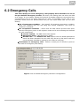
6.2 Emergency Calls . . . . . . . . . . . . . . . . . . . . . . . . . . . . . . . . . . . . . . . . . . . . . . . . 107
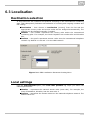
6.3 Localisation . . . . . . . . . . . . . . . . . . . . . . . . . . . . . . . . . . . . . . . . . . . . . . . . . . . . . 108
6.4 Licences . . . . . . . . . . . . . . . . . . . . . . . . . . . . . . . . . . . . . . . . . . . . . . . . . . . . . . . 110
6.4 Licences . . . . . . . . . . . . . . . . . . . . . . . . . . . . . . . . . . . . . . . . . . . . . . . . . . . . . . 110
6.5 Language Packages . . . . . . . . . . . . . . . . . . . . . . . . . . . . . . . . . . . . . . . . . . . . . . 113
6.6 Services . . . . . . . . . . . . . . . . . . . . . . . . . . . . . . . . . . . . . . . . . . . . . . . . . . . . . . . 114
6.7 Conference Rooms . . . . . . . . . . . . . . . . . . . . . . . . . . . . . . . . . . . . . . . . . . . . . . . 116
6.8 Progress Tones . . . . . . . . . . . . . . . . . . . . . . . . . . . . . . . . . . . . . . . . . . . . . . . . . 119
6.9 Ring Tones . . . . . . . . . . . . . . . . . . . . . . . . . . . . . . . . . . . . . . . . . . . . . . . . . . . . . 124
6.10 AutoClip Parameters . . . . . . . . . . . . . . . . . . . . . . . . . . . . . . . . . . . . . . . . . . . . 125
6.11 Storage Manager . . . . . . . . . . . . . . . . . . . . . . . . . . . . . . . . . . . . . . . . . . . . . . . 127
6.12 Scheduled tasks . . . . . . . . . . . . . . . . . . . . . . . . . . . . . . . . . . . . . . . . . . . . . . . . 131
6.13 Status Control parameters . . . . . . . . . . . . . . . . . . . . . . . . . . . . . . . . . . . . . . . . 133
6.14 DTMF . . . . . . . . . . . . . . . . . . . . . . . . . . . . . . . . . . . . . . . . . . . . . . . . . . . . . . . . 134
6.15 Causes . . . . . . . . . . . . . . . . . . . . . . . . . . . . . . . . . . . . . . . . . . . . . . . . . . . . . . . 135
6.16 Time Parameters . . . . . . . . . . . . . . . . . . . . . . . . . . . . . . . . . . . . . . . . . . . . . . . 140
6.17 Assistant . . . . . . . . . . . . . . . . . . . . . . . . . . . . . . . . . . . . . . . . . . . . . . . . . . . . . . 145
7. Routing . . . . . . . . . . . . . . . . . . . . . . . . . . . . . . . . . . . . . . . . . . . 148
7.1 Routers . . . . . . . . . . . . . . . . . . . . . . . . . . . . . . . . . . . . . . . . . . . . . . . . . . . . . . . .
7.2 External Routers . . . . . . . . . . . . . . . . . . . . . . . . . . . . . . . . . . . . . . . . . . . . . . . . .
7.3 Complex Routers . . . . . . . . . . . . . . . . . . . . . . . . . . . . . . . . . . . . . . . . . . . . . . . .
7.4 Switch Routers . . . . . . . . . . . . . . . . . . . . . . . . . . . . . . . . . . . . . . . . . . . . . . . . . .
7.5 Routing Objects . . . . . . . . . . . . . . . . . . . . . . . . . . . . . . . . . . . . . . . . . . . . . . . . .
7.6 Identification Tables . . . . . . . . . . . . . . . . . . . . . . . . . . . . . . . . . . . . . . . . . . . . . .
7.7 AutoClip Routers . . . . . . . . . . . . . . . . . . . . . . . . . . . . . . . . . . . . . . . . . . . . . . . .
8. Users
149
156
158
159
162
197
. . . . . . . . . . . . . . . . . . . . . . . . . . . . . . . . . . . . . . . . . . . . 203
8.1 Users and Groups . . . . . . . . . . . . . . . . . . . . . . . . . . . . . . . . . . . . . . . . . . . . . . .
8.2 User Rights . . . . . . . . . . . . . . . . . . . . . . . . . . . . . . . . . . . . . . . . . . . . . . . . . . . . .
8.3 Extension Types . . . . . . . . . . . . . . . . . . . . . . . . . . . . . . . . . . . . . . . . . . . . . . . . .
8.4 Extensions . . . . . . . . . . . . . . . . . . . . . . . . . . . . . . . . . . . . . . . . . . . . . . . . . . . . .
8.5 Phone Directories . . . . . . . . . . . . . . . . . . . . . . . . . . . . . . . . . . . . . . . . . . . . . . . .
204
215
217
218
223
9. Setting Properties . . . . . . . . . . . . . . . . . . . . . . . . . . . . . . . . . . 229
9.1 Setting Properties . . . . . . . . . . . . . . . . . . . . . . . . . . . . . . . . . . . . . . . . . . . . . . . . 230
10. Billing and Tariffs . . . . . . . . . . . . . . . . . . . . . . . . . . . . . . . . . 243
10.1 Billing and Tariffs . . . . . . . . . . . . . . . . . . . . . . . . . . . . . . . . . . . . . . . . . . . . . . . 244
11. Configuration Examples . . . . . . . . . . . . . . . . . . . . . . . . . . . . 246
11.1 Other Useful Information . . . . . . . . . . . . . . . . . . . . . . . . . . . . . . . . . . . . . . . . . 247
11.2 Mobility Extension Configuration . . . . . . . . . . . . . . . . . . . . . . . . . . . . . . . . . . .
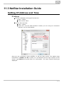
11.3 NetStar Installation Guide . . . . . . . . . . . . . . . . . . . . . . . . . . . . . . . . . . . . . . . . . 263
1. Introduction
Here is what you can find in this chapter:
1.1 About Help
1.2 About Application
1.3 Connecting to PBX
1.4 Configuration Menu
1.5 PBX Activation
5
1.1 About Help
Document format
Document version: 3.1.0
This document serves as a Help and Manual for the configuration of the 2N NetStar
communication system by the NSAdmin program. 2N reserves the right to
modifications.
Conventions
The following fonts are used in the text:
#Hypertext
Hyperlink to another place in the document or outside the document.
#Document contents item
All page headings are listed in the table of content. Clicking an item in the table
of content will display the respective part of the page.
Part
Headings of the individual page topics listed in the table of contents. You can click this
heading and jump to the top (table of contents) of the page where other topics can be
selected.
Important words
The text used in NSAdmin and important words in the text we want to
emphasise are highlighted.
HW – Rack
This form is used instead of a verbal description of the location of an item in the
TreeView (tree in the left-hand part of the NsAdmin window). It means that in
the TreeView you need to click the HW item and then the Rack item in it.
6
1.2 About Application
About Application
NSAdmin is a configuration tool that helps configure the 2N® NetStar communication
system, version 2. The application is designed for an x86 platform using the WINDOWS
operating system connected with 2N® NetStar through a network. It is controlled by a
mouse and, secondarily, a keyboard. NSAdmin uses the TCP connection or modem and
communicates with 2N® NetStar basically via port 6992.
As a necessary condition for using this configuration tool under the Windows XP OS, a
service pack 2 and Framework v.3. have been installed. The program does not work
without these components.
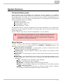
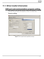
Main menu of the configuration tool
Once the configuration tool has been started, a window is displayed helping to
configure connections to PBXs, analyse traces and start up the Help. The main menu
offers the following options: Admin
Settings – here open a dialogue with the global configuration tool settings.
Language – here choose one of the supported languages.
Exit – push this key to exit the configuration tool.
Trace – operations with previously saved traces are only available here at the
current stage.
Load trace from file
Add trace from file
Trace analyser – push to open a trace analysis window.
Help – here start the Help in the chosen language.
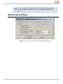
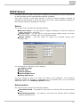
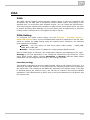
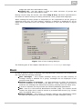
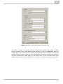
Global settings of the configuration tool
This dialogue includes three tags with the following parameters:
XML script
Type of debugging – use this section to enable and define the range of
displaying the xml trace in the configuration tool. The PBX trace cannot be
set here.
Indent size – use this parameter to define the indent size for the xml
trace.
View – this is an auxiliary function for trace analysis using database.
Show current window name – check this option to display the current
window name in the right-hand bottom corner.
Show object IDs – check this option to display the current object Id in
the right-hand bottom corner. This is an easy way how to know e.g. the
7
port Id and find the port in the trace.
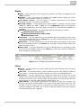
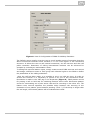
General
Set colours of virtual ports – here define the colour for each virtual port
or disable this function.
Set colours of tables – here define the background colours for tables or
disable this function.
Set colours of logins – here define the colour for each user login or
disable this function.
Set colours of extensions – define the colour for each extension (SIP,
external, etc.) or disable this function.
Click on Default in each of the General subtags to set the default colours.
Advanced – Use the Ask before delete if object is used in
configuration parameter to enable/disable warning display before removing the
router or any of the routing objects from configuration.
Login
Copy devices structure from old version storage – Disable/enable
copying of the the PBX structure(s) from earlier configuration tool versions. Once
copied, the selected PBXs can be removed by deleting only (not by unselecting).
To confirm a configuration setting, use the OK button and to exit the dialogue without
saving, push the Cancel button.
8
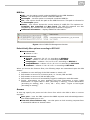
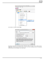
1.3 Connecting to PBX
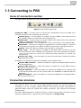
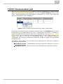
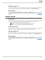
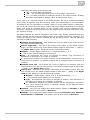
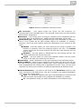
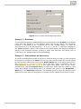
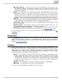
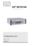
Icons of connection section
The figure below presents all icons of this section.
Figure: View of PBX Login Icons
Connect to PBX – use this icon to connect the configuration tool to the PBX via a
selected connection.Icon meanings from the left:
Create group – use this option to create a group of PBXs on the same level as
the selected object or nested into the existing group.
Create PbX – use this option to create a PBX on the same level as the selected
object or nested into the existing group.
Create connection – use this option to create a connection to the selected PBX.
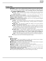
Properties – here set or change the properties of a selected object. A name is
only assigned to groups. For details on PBX and connection settings see below.
Delete – select this option to delete a group, PBX or connection.
Auto login – use this option to enable an automatic PBX connection via the
current connection after starting the configuration tool. One automatic connection
may only be active at a time. By selecting another setting you cancel the
previous one.
Cancel auto login – use this option to cancel the automatic connection without
specifying any object.
In addition, the following options are available in the context menu:
Import PBX structure – select this option to import a predefined PBX structure
as described below.
Export PBX structure – select this option to export the current PBX structure
for later PC connection use.
Import database – select this option to import the database of a selected PBX
in the off-line mode only. In the on-line mode, the database is replaced with the
PBX data.
Export database – select this option to export the database of a selected PBX in
the off-line mode only.
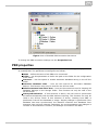
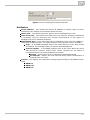
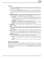
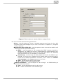
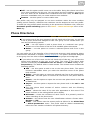
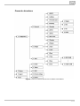
Connection structure
In this menu you can create groups and subgroups (nested groups) and, subsequently,
add PBXs to them. You can create PBXs without groups too, but this might be
confusing if you use a higher number of PBXs. Then you can create connections for
particular PBXs using the TCP/IP and modem protocols. The records are arranged
alphabetically.
For easier administration of existing records, a record moving option using the mouse
has been implemented on this screen, also designated as drag & drop.
9
Figure: View of Possible PBX Connection Structuret
To change the PBX connection settings use the Properties icon.
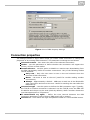
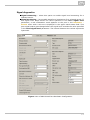
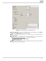
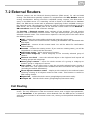
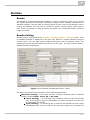
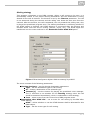
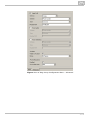
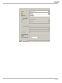
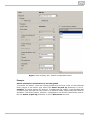
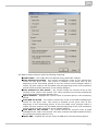
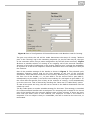
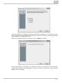
PBX properties
The dialogue shown in figure below helps you create a PBX or change the properties of
an existing PBX. The parameter meanings are as follows:
Name – define the name of the PBX to be connected.
Folder – use this parameter to define the path to the folder for the configuration
to be saved.
Autosave – use this option to enable automatic database saving in the off-line
mode.
Autosave database after – here set the interval for automatic database
backup. This function may only be used for the off-line mode.
Delete autosave item older than – here set the maximum time for keeping old
database backups in the storage folder. This function can only be used in the
off-line mode.
Autosynchronisation – If this selection is active, the tool tries to synchronise
the data automatically with the PBX without inquiring. This function can only be
used in the off-line mode. If this selection is active, 'Loading from PBX' is
performed if the off-line database is empty. 'Display changes' is performed if the
database has been synchronised, the identifier matches and 'Database from
Autosave' has not been selected. Otherwise, the synchronisation type dialogue is
invoked. If this selection is inactive, the dialogue is invoked in all cases.
10
Figure: View of PBX Property Settings
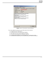
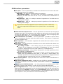
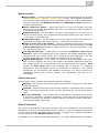
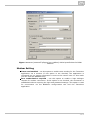
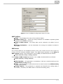
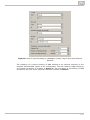
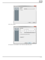
Connection properties
The dialogue shown in figure below helps you create a PBX connection or change the
properties of an existing PBX connection. The parameter meanings are as follows:
Connection name – here enter the name of the selected connection.
Modes – use this parameter to define whether the connection will support the
on-line, off-line or both modes.
Download trace – use this option to disable or restrict trace downloading from
the PBX. Particularly useful for modem connections. *Any of the following modes
can be selected:
Only new – Only the new trace is sent to the tool existent since the
moment of PBX connection.
Never – No trace is sent to the tool (useful for trouble making modem
connections).
Always – Approximately a 300kB – 1MB trace is read out of the PBX buffer
upon connection and sent to the tool. Useful for sending the trace after the
PBX start up.
Connection type – use this option to define the PBX connection type. Typically,
the TCP/IP or modem connection is selected. Use the TCP/IP, enter the PBX CPU
IP address and the port to be used (6992 by default). With a modem choose the
one that supports the X.75 protocol.
If unsuccessful try again – define the time interval between the PBX
connection attempts in case of failure (PBX switch-off or restart).
Connect as – here define the login and password data for a secured PBX access.
11
Figure: View of Connection Property Settings
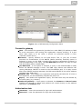
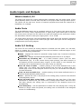
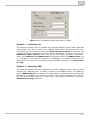
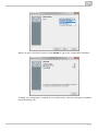
Connecting to PBX
After an automatic or manual initiation of a PBX connection, the dialogue shown in
figure below is displayed. It provides information on the PBX to be connected, the PBX
firmware version (if detected), the last known connection error and, in the case of
automatic connection attempts, also the remaining time to the next attempt. To
connect immediately (before the timeout), push the Try again button. The Cancel but
ton is used for leaving the dialogue.
12
Figure: View of Connection Course Dialogue
If you are unable to connect to your PBX, please check whether:
1. the PBX has been switched on;
2. the PBX has been connected to the network;
3. both sides have the same IP address and port;
4. the used communication port has been opened;
5. the appropriate firmware and configuration tool versions are used;
6. the used communication port is not blocked by your antivirus software.
13
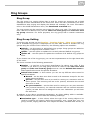
1.4 Configuration Menu
Main menu
After a successful connection to the PBX, the configuration part of the application is
displayed. The main menu of this view is shown in figure below and contains the
following options:
Administrator
Logout PBX – use this option to logout the configuration tool from the PBX
and return to the previous menu for another connection as described
above.
Connect/Disconnect – use these options off-line to connect/disconnect
the configuration tool to/from the PBX.
Save changes – here save all changes made since the last save.
Undo changes – here cancel all changes made since the last save in a
menu.
Settings – use this option to invoke a global setting dialogue as described
in Chapter 1.2 About Application.
Language – choose one of the supported languages.
Exit – use this option to exit the configuration tool.
Trace
Load trace from file – use this option to load a trace from the file, thus
clearing the previous one.
Add trace from file – use this option to load a trace from the file and add
it to the existing one. You can interconnect traces for easy analysis.
Save trace to file – use this option to save the current on-line trace to a
file. The configuration tool always saves an entire trace independently of
whether the filter is being applied or not.
Trace analyser – here open the trace analysis window.
PBX
Upgrade – select this option to display a firmware upgrade dialogue.
Having been chosen, the firmware file is uploaded into the PBX and
unpacked. After a restart, the new firmware is used.
Import logs from PBX – select this option to get an easy access to the
PBX logs without using other applications. You can import All logs or
selected logs only (Selectively).
All – after selecting a directory, the config.db and aoc.db files and the
contents of the internal/log and /var/log directories are imported.
Selectively – select this item to display a dialogue for downloading
selected logs from the PBX. The user can enter the files through a storage
as defined in the Global Data – Storage Manager menu.
Restart PBX – use this option to initiate the PBX restart.
Restart ústředny – Volba umožňuje restart ústředny.
Restore factory settings – use this option to restore the factory default
values. Choose one of the two options available in the dialogue window and
press OK twice to confirm the selected action.
Wizards
Activation wizard – for details refer to the next chapter, 1.5 PBX
Activation.
Import/export company structure – here invoke the company structure
14
import/export dialogue. The csv and xml files are supported.
Database import – click on this option to display the database importing
window. Select From file or From PBX. If you choose From PBX, all the
PBXs available for database import will be displayed. Use the Rule
parameter to specify which of the original settings should not be
overwritten by database import. The option is available in the off-line mode
only.
Database export – click on this option to export the PBX database into an
xml file. The option is available in the off-line mode only.
Help – select this option to start the help in the chosen language.
Figure: View of Configuration Tool Main Menu
Figure above also includes all configuration menu icons. Icon meanings from the left:
Logout PBX – use this icon to logout the configuration tool from the PBX and
return to the previous menu for another connection as described above.
Connect/Disconnect – use these icons off-line to connect/disconnect the
configuration tool to/from the PBX.
Save changes – use this icon to save all changes made since the last save.
Undo changes – use this icon to cancel all changes made since the last save in
a menu.
Language – flags are used to mark the configuration tool language versions.
Windows
On the left-hand side of the configuration tool you can find the TreeView where you can
choose a menu item to be configured. The selected menu then opens on the right-hand
side and is mostly divided into two subwindows; one for selecting and the other for
configuring an object. The configuration is divided into tags for easier orientation. All
the above mentioned windows are shown in the figure below.
15
Figure: View of Configuration Tool Tags and Windows
The Trace and Database sections situated in the lower part of the screen above the
status bar are important configuration tool components. Trace helps you monitor calls
and analyse configuration errors if any. Database provides a direct view of the data
stored (depending on the connection mode). We strongly recommend that you
should not change the data in this view if you do not know how! This menu tag
is governed by the read & write rights assigned to each login.
Status bar
The status bar is a lower task bar in the configuration tool. It provides two important
pieces of information. The first one is the connection mode, which is either on-line or off-line. The other is the connected PBX name, which includes the PBX and connection data separated with a dash.
Figure: View of Configuration Tool Status Bar
16
1.5 PBX Activation
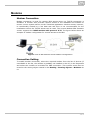
What you need
To activate and configure 2N® NetStar you need the 2N® NetStar system, a
computer running the supported Windows version, a keyboard and a mouse. The PC
and 2N® NetStar PBX have to be interconnected in a LAN. Furthermore, it is
necessary to display the redirected standard PBX input and output on your PC console.
To do this, you need a six–wire, crossed cable with a six-pin RJ-12 connector on one
end and a serial connector on the other. This cable is supplied as standard equipment.
You can use a 'Tera Term Pro' console or any other functional console. You can also
work in the HyperTerminal mode, but longer lines are interlaced.
Step 1: IP address setting
Prior to starting configuration you need to set up the PBX IP address to establish
network communication between the system and the computer. To do this, you can use
a serial console or the default IP address 192.168.100.100. The 2N® NetStar – PC
communication can be on-line or off-line. To configure the console use the table below.
Speed
115200
Bits
8
Parity
None
Stop bits
1
Flow control
None
If necessary, a serial port or modem may be used for PBX connection through the
configuration tool, yet at a considerably lower bit rate.
17
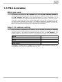
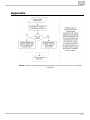
Step 2: Hardware activation
After the first connection to the selected PBX according to the Connection to PBX
chapter, a configuration wizard is displayed as shown in figure below. This wizard is
displayed only if the PBX has a new empty database (has not been preconfigured
according to your demands).
18
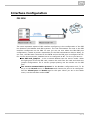
Figure: View of Hardware Configuration Wizard Dialogue
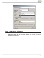
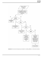
If the wizard is displayed, you can define the basic configuration settings of the virtual
BRI ports. If you are not sure, you can push the Next button to proceed to the next
configuration step because these settings may be changed any time later. Once you do
that, the configuration tool (together with the PBX) starts to detect the hardware as
shown in figure below. 19
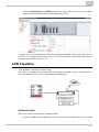
Figure: View of Wizard's Hardware Detection Operations
The boards are detected both in the basic unit and extenders. Once some hardware is
detected, activation takes place, which means that virtual ports are assigned to all the
boards detected (except for VoIP boards). The terminals connected are detected in the
last stage of the wizard hardware configuration. This should make the PBX ready for
further configuration, which is signalled by green board LEDs. The GSM board is the
only board without LED indicators and so its ready status is signalled by the port LEDs.
The current firmware version is loaded into the PBX after the first start–up or every
firmware upgrade and may cause a short delay in the GSM board activation.
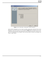
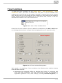
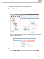
Step 3: Localisation setting
Localisation setting is another important step of the 2N® NetStar configuration. In this
step you can define the parameters shown in figure below and described in detail in the
6.3 Localisation chapter. In addition, you can add a language package of your own
including texts and progress tones. Two language packages – Czech and English – are
available in the PBX by default.
20
Figure: View of Wizard's Localisation Setting Operations
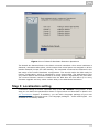
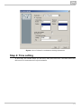
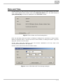
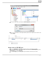
Step 4: Time setting
In this step, the wizard helps you set time, date and time zone. And also define the
NTP server for automatic time synchronisation.
21
Figure: View of Configuration Wizard's Time Setting
Step 5: PBX function selection
In this step, choose one of the PBX modes. The setting is not final, it just defines the
wizard's next configuration steps. The following options are available:
Private branch exchange
Virtual branch exchange
GSM gateway
Hotel
The offer of settings depends on the PBX mode selected. The lowest number of settings
are available in the GSM gateway, where some steps are omitted and configuration
starts as late as the SMTP. The settings are identical for the other modes except for
step 1, which is always adapted to the particular version. The following steps are
available in the Private branch exchange.
22
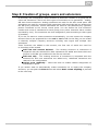
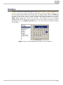
Step 6: Creation of groups, users and extensions
In this step, the configuration wizard enables an automatic creation of a group and its
users and extensions. There are three types of extensions to be generated – analog,
SIP and Cornet extensions. Analog extensions are used for the ASL virtual ports. SIP
extensions are used for connecting SIP–supporting VoIP terminals and are assigned to
the SIP proxy terminals. Cornet extensions are used for the StarPoint key (system)
phones connected to the Cornet virtual ports. You can define the first extension
number and count of extensions for each group (every other extension has a number
increased by one). The extensions are then assigned to ports according to their types
(if possible).
If you do not want to create extensions automatically, you can import the company
structure from a pre–prepared file in the xml or csv format. In this way you can create
a relatively complex company structure including user logins and multiple user
extensions.
Three functions are added to this section, the first two of which are used for
re–launching of the wizard.
Add new and remove deleted – The existing structure of extensions is
compared with the selected file. New extensions are added and those which are
present in the PBX yet undefined in the file are removed.
Add new only – The existing structure of extensions is compared with the
selected file and new extensions are added only. Undefined extensions are
retained in the configuration.
Assign ports randomly–– select this item to enable random assignment of
extensions to ports.
If you neither want to automatically create extensions nor to import the company
structure, you can push the Next button and select Don't create anything to proceed
to the next step.
23
Figure: View of Wizard's Extension Creation or Intra–Plant Structure Import
Step 7: Settings for Assistant
This configuration step includes just two functions with the following meanings:
Launch web server – this item launches the internal PBX web server, to which
you can log in by entering the CPU IP address from your web browser.
Generate default logins – this item generates logins for the users created in
the preceding step. With them, you can log in to the web server as a user.
Step 8: SIP domain setting
This step helps you define a specific SIP domain. If this option is not selected, the CPU
IP address is used as the domain.
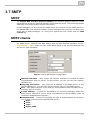
Step 9: SMTP setting
Within this step you can define the SMTP server to be used by the PBX. Port 25 and the
CPU Ethernet interface are set automatically for the SMTP. No security is used by
default.
24
Step 10: Creation of routers
The wizard's last step is creating PBX routers. Routers are used for call/SMS routing
from one PBX port to another. The wizard offers several default sets of routers, which
are sufficient for your basic call routing. For special routing demands, reconfigure the
routers and add new ones. All new routers are automatically filled with services,
extensions and users and linked with each other.
Step 11: Data saving
Changes are not automatically stored into the PBX during the Wizard process. To save
the changes, use the Ctrl+S shortcut or the Save button after completing the Wizard.
To cancel all new settings, push the Undo button.
25
2. Hardware
Here is what you can find in this chapter:
2.1 Basic
2.2 Boards
2.3 Synchronisation
2.4 Board and Port List
26
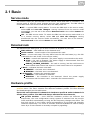
2.1 Basic
Service mode
The section helps you put the PBX in the service mode and back if necessary. The
service mode is used for quick changes such as card replacement. The PBX start is
much faster after the service mode than after the PBX power off.
OFF – a normal PBX running status. To reuse the PBX while in the service mode,
select OFF and save the changes. Having returned from the service mode
successfully, you can see in the section Detected rack in the column Status the
state RUN.
ON – the PBX service mode. To switch the PBX into the service mode while it is
in a normal running status, select ON and save the changes. Having
transferred into the service mode successfully, you can see in the section Detected rack in the column Status the state STOP.
Detected rack
The detected rack table gives you a clear overview of all parts of your PBX.
MAC address – MAC address of the detected rack.
Serial number – serial number of the detected CPU card.
State – current rack state. This may differ from the CPU card state (e.g. the CPU
is ON while the rack if OFF in the service mode).
RUN – normal rack operation. The power supply is connected to the cards.
STOP – the rack is stopped. The power supply is disconnected from the
cards. Typical for the service mode.
ERROR_LICENCE_EXPIRED – the rack is running, but the trial licence or
time-limited main licence has expired. A new licence has to be requested.
1:Basic – indicates the basic unit state.
PRESENT – the basic unit is detected.
MISSING – the basic unit is not detected.
2-5:Extender – displays the extender state.
PRESENT – the extender is detected.
MISSING – the extender is not detected. Check the power supply
connection and the switch card - extender CPU interconnection.
Hardware profile
To set the hardware profiles and improve your system efficiency use the HW – HW
profiles menu. The menu contains five different hardware profiles. For their benefits
and disadvantages see the table below.
Each VoIP card allocates 32 channels in hardware profile 0 and 64 channels in
all the other profiles. The PRI card always allocates 32 bus channels.
HW profile number – since different hardware profiles use different bus
frequencies, the new configuration saving system is switched into the service
mode and back automatically to bring the bus frequency changes into effect. The
bus clock can be 2, 4 or 8 MHz, which corresponds to 32, 64 nebo 128 extender
channels respectively. The count of extender channels available for calls is always
lower by 4 as one channel is normally occupied by signalling.
27
Profiles
Extenders
Extender channels
Trunk positions
Main case case – digital
Main case – analog
Detectors
Players
0
4
128
128
128
32
32
32
1
0
0
256
64
32
64
64
2
4
32
224
64
32
64
64
3
4
64
192
64
32
64
64
4
4
128
128
64
32
64
64
5
0
0
224
64
64
64
64
6
4
32
192
64
64
64
64
7
4
64
160
64
64
64
64
8
4
128
96
64
64
64
64
Table: Benefits and Disadvantages of Hardware Profiles
28
2.2 Boards
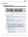
Arrangement of HW
Unfolding the HW – Rack menu you can see the rack fitting as shown in the figure
below.
Figure: View of PBX Basic Unit Panel
Push the buttons on the left-hand side of the PBX to switch between the basic unit and
extender views. Click on the right-hand mouse button in the basic unit or extender
view to display the following options:
Add board – click on an empty (no-board) PBX position to use this option. Add a
board that has been detected by the PBX (using the Detected option) or a board
from the list of supported boards for this position.
Remove board – use this option to remove a selected board. If virtual ports or
resources have been assigned to the board, you will be asked whether they
should be removed or retained.
Migrate virtual port/resource – use only if the context menu has been
displayed on a port to initiate a virtual port substitution dialogue.
Synchronise with detected – use this option to synchronise the current unit or
extender with the detected PBX boards. Before a board is removed from the
current configuration, you are asked to confirm the removal.
Expert menu – use this option to access the advanced unit, board or port
configuration functions. For details see later.
Let us explain the terms "virtual port" and "physical port" and their
difference for convenience. Basically, a virtual port is used for
software setting of basic properties of a physical port. The advantage
of this approach is the fact that the defined set of properties is
attributed to a physical port only if the virtual port is assigned to it.
Thus, you can esily move virtual ports between physical ports and
change their functions as necessary.
Expert menu – Virtual port
Assign virtual port/resource – use this option to assign an existing
virtual port to a physical port. Select a virtual port from the list of existing
ports.
Create virtual port/resource – use this option only for physical ports
without any assigned virtual port. The new virtual port is automatically
assigned to this physical port.
Remove virtual port/resource – use this option to remove a virtual port
29
from a selected physical port without deleting it. This virtual port can be
used later including all settings (routing, assigned extensions, etc.).
Rename the virtual port from XXX to UnassignedXXX.
Delete virtual port/resource – use this option to remove and delete a
virtual port once forever. You will not be able to use this port any more.
Regenerate name – use this option to rename a selected virtual port
according to its physical port.
Expert menu – Board and Case
Create virtual ports/resources – use this option to create virtual ports
(resources) for all of those physical board or unit ports at once that have
not been assigned a virtual port.
Remove virtual ports/resources – use this option to remove all virtual
board or unit ports at once without deleting them. These ports can be used
later including their settings. Rename these virtual ports from XXX to
UnassignedXXX.
Delete virtual ports/resources – use this option to delete all virtual
board or unit ports once forever. You will not be able to use this port any
longer.
Regenerate unchanged names – use this option to change all
unchanged names of the virtual board or unit ports according to their
physical ports.
Regenerate all names – use this option to change the names of all virtual
board or unit ports according to their physical ports.
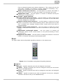
Board
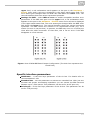
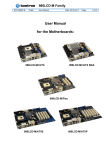
The figure below shows all possible signalling statuses on the board ports.
Figure: View of Available Analog Board Signalling Statuses
Earphone
Cross
Green – signals a physical port with an assigned virtual port.
Yellow – signals a physical port with an assigned virtual port and active
call (or call establishment).
Green – signals a physical port with an assigned virtual port and assigned
extension.
Yellow – signals a physical port with an assigned virtual port, assigned
extension and active call (or call establishment).
30
Exclamation mark
Yellow – signals a physical port without any assigned virtual port or
physical port without detected status.
Red – signals a hardware error, e.g. a low signal level for a GSM, GSM port
without SIM card, ISDN virtual port with deactivated L1 or L2 (adjustable),
etc.
PBX HW configuration print
The buttons to the right of the basic unit/extender figure help you print out the current
PBX hardware configuration. Click on one of the buttons to display the print setting
options. Click on Print to display the preview and on the button in the left-hand upper
corner to print out the configuration. The buttons in the right-hand upper corner
display the extender configuration previews.
Print current view – print the view selected using the buttons to the left of the
CPU board (basic unit or extender).
Print all – print the basic unit and extender configurations.
Boards
A two-part Boards tag is available under the PBX view. The upper part shows basic
information on the selected board. The parameters mean the following:
Position – gives the board position number in the case as described below.
Type – gives the type of the board to be configured.
Enabled – disables the selected board. This option is useful, for example, while
changing SIM cards without switching off the PBX.
State – provides the current board status including information on a mismatch of
the board to be configured with the detected one.
Detected – shows the parameters of the board detected.
Type – type of the board detected on a selected position.
Serial number – serial number of the board detected on a selected
position.
MAC address – MAC address of the board detected on a selected position.
A window showing the list of physical ports of the selected board is displayed under the
above-mentioned part. The meaning of each list column is explained in the 2.4 Board
and Port List chapter.
Tab Virtual port
The Virtual port tag helps you configure your virtual ports easily. You can set all
parameters of the selected virtual ports and simultaneously see the panel layout. Use
the Virtual port tag for an easy configuration of virtual ports. The tag includes all
configuration settings for the selected virtual port while keeping the PBX view. Click on
a card or its port to display the port assignment to a virtual port type in the left section
of the screen. Use the drag&drop function to move a virtual port to another type. If you
select the CPU card, all the virtual ports that use the card's LAN interface are
displayed. Thus, you will see the SIP Proxy and SIP Gateway virtual ports as well as
the SMTP and SMTPD virtual ports.
For details on the setting options associated with the parameters in the right-hand
section of the tag refer to the User Manual chapters dedicated to particular virtual ports
(especially 3. Virtual Ports).
31
Addressing
The position of each board is specified in the R : C : B format and the position of a port
in the R : C : B : P format. The characters have the following meanings:
R – rack number;
C – rack unit number;
B – unit board number;
P – board port number.
Currently, R takes up the value of 0 and C ranges from 1 to 5, the basic unit being 1,
the first extender 2 and so on up to the fourth extender with number 5. The board
positions (B) in the basic unit are numbered 1 to 14 from the left. The extender
positions are numbered similarly, from 1 to 12. The first basic unit and extender
position is always reserved for the CPU board. The 1x/2x/4x ISDN PRI (with or without
Zarlink) or Surf Ethernet boards can be mounted into positions 0:1:2 to 0:1:4 only.
The position 0:1:5 is reserved for the Switch board, which contains the digital
switching array.
32
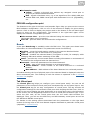
2.3 Synchronisation
Upon connection to a public or private ISDN network, remember to configure one port
for synchronisation at least. The PBX works in two modes at the same time: as a
source of synchronisation (Master) and a device that receives synchronisation (Slave).
There are two fields in the HW – Synchronisation menu. The left-hand one contains
all digital virtual ports that can be selected for synchronisation, i.e. all PRI and BRI
virtual ports in the TE mode. The other field contains a list of virtual ports that have
been selected for synchronisation. All ports in the NT mode can be used as
synchronisation sources.
Figure: View of Synchronisation Port Assigning and Priorities
Use the Up and Down buttons to move the selected synchronisation up or down for a
higher or lower synchronisation priority respectively – the port listed first has the
highest priority (255). Every other carrier has a priority lower by 1 (254, 253, ..). A
newly assigned carrier is always placed last (the lowest priority). In the case of
synchronisation loss, the following port in the list (with a lower priority) is selected
automatically. Upon synchronisation restoration, the PBX returns automatically to the
port with the highest priority.
Push the Right and Left buttons to transfer the virtual ports from one field to another
and thus ensure the PBX synchronisation.
33
2.4 Board and Port List
The Hardware – Board list menu contains a list of boards that are physically present
in the PBX. The board list has four columns with the following meanings:
Address – shows the physical board address within the PBX according to the Boards chapter.
Type – shows the board type.
Serial number – shows the factory-programmed board serial number.
MAC address – shows the board MAC address.
Module IMEI – shows IMEI of GSM module.
Virtual port – shows the complete name of the carrier or resource assigned to a
physical port.
Stack – shows the general carrier / protocol stack (DSS1, ASL, CO, etc.).
Extension – shows the list of extensions assigned to a physical port carrier.
User – shows the users of extensions assigned to a physical port.
State – shows the current port state.
Description – provides associated information.
The context menu under the right button offers the following two options:
Export to CSV – use this option to export the whole table into a *.CSV file. You
can use this export for stocktaking purposes and/or for contacting the 2N®
TELEKOMUNIKACE Technical Support if necessary.
Move to port – use this option to move quickly to the configuration of the virtual
port on the selected row.
34
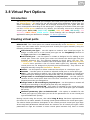
3. Virtual Ports
Here is what you can find in this chapter:
3.1 BRI and PRI
3.2 Cornet
3.3 ASL
3.4 CO
3.5 GSM
3.6 SIP
3.7 SMTP
3.8 Virtual Port Options
35
3.1 BRI and PRI
BRI
Refer to the Boards section for the meaning of the virtual port.
BRI virtual ports are assigned to physical ISDN ports for the Basic Rate Interface. For
the hardware configuration of BRI virtual ports refer to the Virtual ports – BRI/PRI menu in the Stack tag. A list of all BRI virtual ports is displayed on the left and a
window for the port parameter setting is available on the right. The configuration
parameters are divided into logical parts.
Stack status
This field displays information on the stack and its current status including information
on the L1 or L2 states, higher error rates or loss of synchronisation.
Digital interface parameters
Interface type – cannot be selected, only shows the type of interface including
bit rate information.
Interface mode – use this parameter to switch between the NT (Network
Termination) and TE (Terminal Equipment) modes. Some basic unit positions can
only be used in the NT mode. Specifically, they are basic unit board positions 6, 9
and 12 if you follow addressing as described in Boards. A correct function
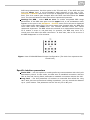
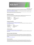
requires a software–hardware matching and a proper jumper setting for each
board port. Figure below may serve as a guide.
Do not remove the board from the PBX without prior PBX switching off
or into the service mode to avoid the PBX damage.
Bus mode – use this parameter to switch between the MPT
(point–to–multipoint) and PTP (point–to–point) modes. In the MPT mode you can
connect up to eight terminals to one physical port. The PTP mode is mainly used
for cross–connecting lines (trunks) between PBXs or for one terminal connection.
Enabled channels – use the checkboxes to activate the B–channels. If no
channel is checked off, you cannot use this port for communication (it behaves as
if busy).
Deactivate L1 at relax – use this parameter to deactivate the L1 layer on an
inactive interface. The PBX automatically deactivates the layer after a timeout as
defined in the Deactivation timeout item. Any incoming call automatically
reactivates this layer.
Keep L1 active – check this option to make the PBX keep L1 active on this
interface without any incoming call. This option cannot be combined with the Deactivate L1 at relax option.
Inactive L1 as error – use this option to activate a caution about the first layer
being inactive. This is indicated by a red exclamation mark on the port in the Hardware – Boards menu and a red text in the upper stack status field. This
option may not combined with the Deactivate L1 at relax option.
Set SLIP – select Nonsynchronous as error to enable acceptable SLIP range
parameters. Use this option in the TE mode only. If the SLIP rate gets over the 36
upper level, a red exclamation mark appears on the port in the Hardware –
Boards menu and a red text is displayed in the upper stack status field. This
error status gets changed after the SLIP rate falls below the lower level. The
interval between these two values represents hysteresis.
Settings for BER – select BER as error to enable acceptable interface error
parameters. If the BER rate gets over the upper level, a red exclamation mark
appears on the port in the Hardware – Boards menu and a red text is displayed
in the upper stack status field. This error status gets changed after the BER value
falls below the lower level. The interval between these two values represents
hysteresis. The BER values are entered in an exponential format (e.g. 3e–5
means 3 errors in 100,000 bits). In practice, the BER may occur on a virtual port
close after the cable connection. In that case, this is not an error if the BER
disappears in a few minutes.
Figure: View of ISDN BRI Board Jumper Configuration (The thick line represents the
board front)
Specific interface parameters
Multiframe – is the first layer parameter of the So bus. For details refer to
recommendation I.430.
Extended bus – use this parameter to activate an extended bus. With just one
terminal and proper terminating impedance you can extend the PBX–terminal
distance up to 1,000 metres. This parameter can be set for an NT port only.
Priority 10 – is the first layer parameter of the So bus. This parameter can be
set for a TE port only.
37
DSS1 protocol parameters
Reverse NT/TE mode – this option refers to L3 signalling only. Check this
option to make a TE port behave as an NT port (and vice versa).
Do not send time at NT – use this option to disable sending of the connection
date and time information within the CONNECT message from an NT port to a TE
port. Available for NT ports only.
Ignore unset explicit channel – use this option to enable call establishment
without an explicitly set B–channel.
Always select B–channel – use this option to disable sending the channel
identification information within the SETUP message together with channel
signalling. Available for TE ports only.
Disconnect L2 if there is no call – use this option to disconnect the L2 layer
on a inactive interface. The PBX automatically disconnects the layer after a
timeout. An incoming call automatically reconnects the layer.
Keep L2 connected – check this option to make the PBX to keep L2 connected
on this interface without any incoming call. This option may not be combined
with the Disconnect L2 if no call option.
Disconnected L2 as error – use this option to activate a caution about the
second layer being disconnected. This fact is indicated by a red exclamation mark
on the port in the Hardware – Boards menu and a red text in the upper stack
status field. This option may not be combined with the Disconnect L2 if no call
option.
Terminals – is active for virtual MPT NT ports. Enter all connected ISDN
terminals including their MSN numbers. Assign a extension to these terminals
using the Extensions tag. The terminal shall then identify itself as the selected
extension within the PBX.
2N® NetStar is able to process (i.e. resend to an interface other than
ISDN) only G.711 A-law encoded calls on the ISDN interface. Calls
encoded by G.711 µ-law can only be resent between the ISDN
interfaces in the PBX.
Digital interface diagnostic
Line state – the parameter cannot be set. It only shows the state of the first
interface layer.
Number of SLIPs per minute – this parameter gives the count of slips. A slip is
caused by different clocks of the PBX and the active terminal. This value is
updated every 6 seconds and represents a weighted average per minute.
Bit error rate per second – the BER parameter gives a count of incorrectly
transferred bits during transmission. The value is updated every 6 seconds and
represents a weighted average per minute.
If the SNMP port supervision is used, enable some or all of the following parameters: Inactive L1 as error, Disconnected L2 as error, Nonsynchronous L1 as error, BER as error. If not, the port error will not be detected and the PBX will be unable to
send a warning.
38
Tab Expert
Cause mapping – is an additional function for modification of outgoing causes
for a selected virtual port. It may be useful while adapting NetStar causes to the
specific conditions of your network. You can choose a particular internal NetStar
cause in the left–hand column and assign a cause to it to be sent to your network
in the right–hand column.
PRI
Refer to the Boards section for the meaning of the virtual port.
PRI virtual ports are assigned to physical ISDN ports for the Primary Rate Interface.
For the hardware configuration of the PRI virtual ports refer to the Virtual ports –
BRI/PRI menu in the Stack tag. A list of all available PRI virtual ports is displayed on
the left and a window for the port parameter settings is on the right. The configuration
parameters are divided into logical parts.
Stack status
This field displays information on the stack and its current status including information
on the L1 or L2 states, higher error rates or loss of synchronisation.
Digital interface parameters
Interface type – the parameter cannot be configured. It only shows the type of
interface including bit rate information.
Interface mode – use this parameter to switch between the NT (Network
Termination) and TE (Terminal Equipment) modes. A correct function requires a
software–hardware matching and a proper jumper setting for each ISDN board
port. Figure below may serve as a guide.
Do not remove the board from the PBX without prior PBX switching off
or into the service mode to avoid the PBX damage.
Enabled channels – use the checkboxes to activate the B–channels. If no
channel is checked off, you cannot use this port for communication or data
transmission (it behaves as if busy). B–channels 0 and 16 cannot be used for call
or data transmission under normal circumstances since they are blank. In PCMs
of the 1st order are used for frame synchronisation and signalling transmission.
Deactivate L1 at relax – use this parameter to deactivate the L1 layer on an
inactive interface. The PBX automatically deactivates the layer after a timeout as
defined in the Deactivation timeout item. Any incoming call automatically
reactivates this layer.
Keep L1 active – check this option to make the PBX keep L1 active on this
interface without any incoming call. This option cannot be combined with the Deactivate L1 at relax option.
Inactive L1 as error – use this option to activate a caution about the first layer
being inactive. This is indicated by a red exclamation mark on the port in the Hardware – Boards menu and a red text in the upper stack status field. This
option may not combined with the Deactivate L1 at relax option.
Settings for SLIP – select Nonsynchronous as error to enable acceptable
39
SLIP range parameters. Use this option in the TE mode only. If the SLIP rate gets
over the upper level, a red exclamation mark appears on the port in the Hardware – Boards menu and a red text is displayed in the upper stack status
field. This error status gets changed after the SLIP rate falls below the lower
level. The interval between these two values represents hysteresis.
Settings for BER – select BER as error to enable acceptable BER range
parameters. If the BER rate gets over the upper level, a red exclamation mark
appears on the port in the Hardware – Boards menu and a red text is displayed
in the upper stack status field. This error status gets changed after the BER rate
value falls below the lower level. The interval between these two values
represents hysteresis. The BER values are entered in an exponential format (e.g.
3e–5 means 3 errors in 100,000 bits). In practice, the BER may occur on a
virtual port close after the cable connection. In that case, this is not an error if
the BER disappears in a few minutes.
Figure: View of ISDN PRI Board Jumper Configuration (The thick line represents the
board front)
Specific interface parameters
Prefer CRC – use this option to enable preferring communication with the Cyclic
Redundancy Check. In this mode, the PBX tries to establish connection with the
CRC at first and, having failed, attempts to establish connection without the CRC.
Long haul – use this parameter to activate an extended bus called the Long
Haul. With just one terminal and holding impedance, you can extend the distance
up to 1,000 metres. This parameter can be set only on an NT port.
40
DSS1 protocol parameters
Reverse mode NT/TE – this option refers to L3 signalling only. Check this
option to make a TE port behave as an NT port (and vice versa).
Do not send time at NT – use this option to disable sending of the connection
date and time information within the CONNECT message from an NT port to a TE
port. Available for NT ports only.
Ignore unset explicit channel – use this option to enable call establishment
without an explicitly set B–channel.
Always select B–channel – use this option to disable sending the Channel
identification information within the SETUP message with channel signalling.
Available for TE ports only.
Disconnect L2 if no call – use to disconnect the L2 layer on an inactive
interface. The PBX automatically disconnects the layer after a timeout. An
incoming call automatically reconnects the layer.
Keep L2 connected – check this option to make the PBX keep the L2 layer
connected on this interface without any incoming call. This option may not be
combined with the Disconnect L2 if no call option.
Disconnected L2 as error – use this option to activate a caution about the
second layer being disconnected. This fact is indicated by a red exclamation mark
on the port in the Hardware – Boards menu and a red text in the upper stack
status field. This option may not be combined with the Disconnect L2 if no call
option.
Terminals – not applied for PRI ports.
2N® NetStar is able to process (i.e. resend to an interface other than
ISDN) only G.711 A-law encoded calls on the ISDN interface. Calls
encoded by G.711 µ-law can only be resent between the ISDN
interfaces in the PBX.
Digital interface diagnostic
Line state – the parameter cannot be set. It only shows the state of the first
interface layer.
Number of SLIPs per minute – this parameter gives the count of slips. A slip is
caused by different clocks of the PBX and the active terminal. This value is
updated every 6 seconds and represents a weighted average per minute.
Bit error rate per second – the BER parameter gives a count of incorrectly
transferred bits during transmission. The value is updated every 6 seconds and
represents a weighted average per minute.
If the SNMP port supervision is used, enable some or all of the following parameters: Inactive L1 as error, Disconnected L2 as error, Nonsynchronous L1 as error, BER as error. If not, the port error will not be detected and the PBX will be unable to
send a warning.
41
Expert tab
Cause mapping – is an additional function for modification of outgoing causes
for a selected virtual port. It may be useful while adapting NetStar causes to the
specific conditions of your network. You can choose a particular internal NetStar
cause in the left–hand column and assign a cause to it to be sent to your network
in the right–hand column.
42
3.2 Cornet
Cornet is a digital virtual port for the StarPoint key phones with proprietary signalling
(UPN interface). The Stack tag provides limited configuration capacities only. The
parameters are divided into logical sections according to their respective functions. For
the StarPoint configuration parameters refer to the Softphone subtag of the Properties
tag. For more details on Softphone extensions refer to Chapter Setting Properties.
Virtual port status
The upper menu field displays information on the stack type and its current status
including information on the L1 and L2 states, increased bit error rate or
nonsynchronous L1.
Digital interface parameters
Interface type – the parameter cannot be configured. It only shows the type of
interface.
Interface mode – this parameter is set to NT and cannot be reconfigured. Thus,
cross–connecting lines cannot be made using these ports.
Bus mode – this parameter is always set to PTP and cannot be reconfigured.
This port is used for one terminal only.
Enabled channels – use this parameter to enable selected interface channels. If
none is enabled, the interface cannot be used and behaves as if it was busy.
Keep L1 active – check this option to make the PBX keep the interface active
automatically.
Inactive L1 as error – use this option to activate a caution about the first layer
being inactive. This is indicated by a red exclamation mark on the port in the Hardware – Boards menu and a red text in the upper stack status field.
Set BER – select BER as error to enable acceptable BER range parameters. If the
BER rate gets over the BER error level, a red exclamation mark appears on the
port in the Hardware – Boards menu and a red text is displayed in the port
status field. This error status gets changed after the BER value falls below the BER OK level. The interval between these two values represents hysteresis. The
BER values are entered in an exponential format (e.g. 3e–5 means 3 errors in
100,000 bits).
Master terminal
Type – shows the type of the StarPoint terminal connected.
Firmware – shows the current firmware version of the terminal connected.
Extenders – shows information on the active extenders of the terminal
connected.
Slave terminal
Type – shows the type of the StarPoint terminal connected.
Firmware – shows the current firmware version of the terminal connected.
Extenders – shows information on the active extenders of the terminal
connected.
43
Digital interface diagnostic
Line state – the parameter cannot be configured. It only shows the state of the
first interface layer.
Number of SLIPs per minute – shows the count of SLIPs. A SLIP is caused by
different clocks on the PBX and the terminal. This value is updated every 6
seconds and represents a weighted average per minute.
BER per second – the Bit Error Rate shows the count of incorrectly transferred
bits on the interface during transmission. The value is updated every 6 seconds
and represents a weighted average per minute.
Supported terminals
44
3.3 ASL
The ASL virtual port is used for connecting common analogue telephones or fax
machines. This virtual port enables DTMF and pulse dialling detection and as well as
DTMF or FSK using CLIP transmission. The parameters are divided into logical sections.
Stack status
This field displays information on the stack and its current status. With an ASL virtual
port you can see the following statuses:
null
config
on_hook
off_hook
error_stop
error_start_req
Figure: View of ASL Virtual Port Hardware Configuration
Line parameters
Impedance – this parameter determines the impedance of the hybrid circuit
according to preset models (User, ETSI 600, Germany and Real 600).
Line model – this parameter provides further hybrid circuit parameters
according to preset models EIA0 to EIA7 (e.g. EIA0 represents a 100m long line
model).
Signalling type – shows the type of active state signalling. Choose from Reverse polarity, Tariff pulse or Simple.
Tariff pulse type – defines the tariff pulse sending source. Select 12 kHz, 16
kHz or none.
45
Incoming parameters (phone is dialling)
Call type – determines the preferred type of communication on this port. Choose
one of the Voice, FAX, A3.1kHz Audio and 56kb Modem options.
DTMF dial enabled – check this item to make the carrier detect DTMF dialling
from an analogue phone.
Pulse dial enabled – check this item to make the carrier detect pulse dialling
from an analogue phone.
FLASH length [ms] – the parameter sets the maximum time of the FLASH
signal transmitted from a local phone to the PBX. The default value is 150 ms
and the minimum value is 80 ms.
Disable port DTMF detection – use this parameter to disable/enable DTMF
detection using a detector on the board in order to save the internal PBX
detectors.
Outgoing parameters (phone is ringing)
CLI broadcasting mode – the parameter defines the preferred CLIP (Calling
Line Identification Presentation) transmission type. The selections are DTMF, FSK and none.
46
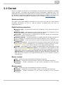
3.4 CO
The CO virtual port is an analogue virtual port for connection of a CO (central
exchange) analogue line. Since it has only a DTMF transmitter, it is unable to detect
the DTMF. Therefore, route an incoming call directly to the final destination, or assign
the DISA function to the virtual port to detect the DTMF symbols and route the call to
the required destination. The parameters are divided into logical sections.
Basic
Stack status
This field displays information on the stack and its current status. With a CO virtual
port you can see the following statuses:
null
config
on_hook
off_hook
error_stop
error_start_req
Figure: View of CO Virtual Port Hardware Configuration
47
Line parameters
Impedance – determines the impedance of the hybrid coil according to preset
models (User, ETSI 600, Germany and Real 600).
Line model – determines further hybrid coil parameters according to preset
models EIA0 to EIA7 (e.g. EIA0 represents a 100m long line model).
Signalling type – shows the type of active state signalling. Choose one of the Reverse polarity, Tariff pulse or Simple options.
Tariff pulse type – defines the tariff pulse sending source. Choose 12 kHz, 16 kHz
or none.
Dial tone –
Congestion tone – this setting becomes available when you tick off the Check
congestion tone parameter. Select the congestion tone mask for testing
purposes.
Check congestion tone – tick off the option to check the presence of the
congestion tone. If the congestion tone is detected, the virtual port will pass into
the On-hook mode.
Outbound way parameters (from PBX)
Current detection timeout [ms] – here set the time for current detection on
the picked-up carrier. If no current is detected within this timeout, a failure is
reported.
Dial tone timeout [ms] – here set the waiting time for dialling numbers to the
carrier. Select the Check dial tone option to test the dial tone presence during
this time.
Dial to connect timeout [ms] – here set the maximum delay time for CO line
dialling. Time monitoring is renewed after every digit entered. If no digit is
detected within this timeout, the connection will be regarded as terminated and a
new connection attempt will be made.
Check dial tone – select this option to enable dial tone testing on the carrier for
a period of time set in the Dial tone wait timeout parameter.
DTMF dial enabled – tick off the option to enable DTMF dialling for the virtual
port
Pulse dial enabled – tick off the option to enable pulse dialling for the virtual
port
FLASH length [ms] – here set the maximum time of the FLASH transmitted
from a local phone to the PBX. The default value is 150 ms and the minimum
value is 80 ms.
48
Inbound way parameters (to PBX)
Ring pulse time [ms] – this parameter sets the minimum time of the ring
signal presence needed for ring detection. If the ring time is shorter than the
preset value, ringing will be ignored.
Ring pulse treshold [V] – this parameter sets the minimum ring voltage level
needed for ring detection. If the ring voltage level is lower than the preset value,
ringing will be ignored.
Ring pattern time [ms] – this parameter sets the minimum period of time for
alerting detection.
CLI reception mode – the parameter defines the preferred CLIP (Calling Line
Identification Presentation) reception type. Choose DTMF, FSK or none.
CLI reception timeout [ms] – the parameter sets the CLI detection timeout as
counted from the end of the first ring. This option is active only if the DTMF or FSK reception mode has been selected.
Polarity timeout [ms] – the parameter sets the reverse polarity timeout. This
option is active only if the Reverse polarity item has been selected for this
virtual port.
Call reject timeout [ms] – if the PBX needs to reject an incoming CO call, it
has to pick up and hang up. Use this parameter to define the timeout for this
action. If the action is too short, the other party will not recognise termination.
Expert
Chipset
Chipset Type – this parameters determines the type of the chipset used. The
SILABS_SI350 chipset is only supported at present.
Chipset Config – activates one of the chipset configurations created.
New config – helps create a new configuration for the selected chipset type.
Specific Chipset Config
Name – sets the chipset type whose configuration is being set in the section.
Do not change the above mentioned parameters unless absolutely
necessary.
DCTerm – sets the DC termination parameters (ringing voltage, minimum
current, impedance). Hexadecimal values are used.
DAA Ctrl 5 – sets further parameters for analogue line matching (on/off-hook
rate, low pass filter). Hexadecimal values are used.
ACIM – helps set the proper impedance. Hexadecimal values are used.
Tx Gain – sets the transmit gain.
Rx Gain – sets the receive gain.
Refer to pages 78 to 81 of the User Manual for more details on the
parameters.
The table below includes the ACIM settings including meanings.
49
ACIM
[3:0]
0000
00
600 Ohm
0001
01
900 Ohm
0010
02
270 Ohm + (750 Ohm || 150 nF) and 275 Ohm + (780 Ohm ||
150 nF)
0011
03
220 Ohm + (820 Ohm || 120 nF) and 220 Ohm + (820 Ohm ||
115 nF)
0100
04
370 Ohm + (620 Ohm || 310 nF)
0101
05
320 Ohm + (1050 Ohm || 230 nF)
0110
06
370 Ohm + (820 Ohm || 110 nF)
0111
07
275 Ohm + (780 Ohm || 150 nF)
1000
08
120 Ohm + (820 Ohm || 110 nF)
1001
09
350 Ohm + (1000 Ohm || 210 nF)
1010
0A
0 Ohm + (900 Ohm || 30 nF)
1011
0B
600 Ohm + 2.16 µF
1100
0C
900 Ohm + 1 µF
1101
0D
900 Ohm + 2.16 µF
1110
0E
600 Ohm + 1 µF
1111
0F
Global complex impedance
Set
AC termination
50
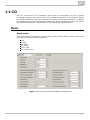
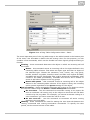
3.5 GSM
The Virtual ports – GSM menu provides a list of all GSM virtual ports of the PBX. The
parameters are divided into logical sections.
Basic
Stack status
This field displays information on the stack and its current status.
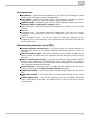
Network selection
Net type selection – select the preferred network for module login. The
following options are available:
Any
Only GSM
Prefer GSM
Only UMTS
Prefer UMTS
Roaming enabled – use this option to enable roaming for a GSM virtual port.
Manual network selection – if not checked, the SIM card tries to log into the
preferred network automatically. If checked, enter the correct Network code to
make the SIM card log into the selected network only. If the selected network is
unreachable, the SIM card will not try to log into another network.
Network code – fill in a 5–digit international network code (e.g. T–mobile
CZ=23001, O2 CZ=23002, Vodafone CZ=23003).
Network name – enter the name of the network as coded in the Network
code parameter.
Cell selection – select the network cell to which the module shall/may log in.
Off – the cell is selected automatically.
Prefer selected – the module tries to log in to the cell specified in the
parameter below. If unsuccessful, the module tries other available cells.
Only selected – the module only tries to log in to the cell specified in the
parameter below.
Cell ID – set the network cell identifier for module login.
The following options are available under the right mouse button:
Known networks – use this option to open a dialogue with the list of known
networks and their international GSM codes. The networks are arranged
according to countries.
Visible networks – use this option to open a dialogue with the list of visible
networks in the surroundings. By initiating the search you make your SIM card
log out temporarily from the module.
51
Signal diagnostics
Signal measuring – select this option to enable signal level measuring for a
selected carrier.
Signal monitoring – here enable signal level monitoring for a selected carrier. If
the signal level drops below the value specified in the Poor signal level
parameter, a red exclamation mark appears on the port in the Hardware –
Boards menu and a red text is displayed in the upper stack status field. This
poor signal status gets changed after the signal level exceeds the value specified
in the Good signal level parameter. The interval between the values represents
hysteresis.
Figure: View of GSM Virtual Port Hardware Configuration
52
GSM interface parameters
CLI mode – use this parameter to enable CLI restriction for the active SIM card.
The following options are available:
By SIM – the SIM card default setting is respected.
By calling number – the calling user CLI setting is respected. If CLI is
allowed, the SIM card uses CLI too. If not, the SIM card's identification is
restricted.
Presented – SIM CLI is always restricted regardless of the SIM card or
calling user settings.
Restricted – SIM CLI is always presented regardless of the SIM card or
calling user settings.
This function must be supported by the network provider. Otherwise,
calls with suppressed identification are rejected with a corresponding
cause.
Relax interval between calls – use this parameter to determine the idle period
between two calls. This parameter only applies to calls going out from the PBX
through the GSM carrier, not to incoming calls. During this time all outgoing calls
are rejected with cause 34 – no circuit/channel available.
DID transmission in number – use this parameter to enable a special direct
dial–in transmission function within the called number. This function is supported
by some networks only.
DID separator – this character separates the called SIM card number and the
DID (direct dial–in).
DID mode – use this parameter to define how to work with the DID. Select one
of the following options:
By calling number – if the calling user has CLI restriction, the calling
number is not displayed in the DID (777982494#). If not, the calling
number is displayed behind the DID separator (777982494#274).
Always presented – CLI is always presented in the DID regardless of the
CLI setting (777982494#274).
Restricted DID replace – the mode is similar to the By calling number
mode; the only difference being that, in the case of CLIR enable, the
identifier specified in the DID replace pattern parameter is displayed behind
the DID separator instead of the CLI (e.g. 777982494#888).
DID replace pattern – specify the DID to be used as the caller's identification in
the case of CLIR.
DID off for emergency calls – disable the use of DID for specified emergency
calls while the PBX is in one of the modes as described in detail in the Emergency
Calls menu.
Diasable port DTMF detection – use this parameter to disable/enable DTMF
detection using a board detector in order to save internal PBX detectors.
Send congestion tone – if this item is selected and the port requires tones, the
PBX generates the congestion tone to the other party after the call end until the
port receives the Release message or the 30s timeout expires. If this item is
not selected, the channel is closed practically on the telephone hang–up. If the
port requires no tone, the channel is closed immediately too.
53
GSM modul diagnostic
Producer – provides information on the board manufacturer.
Type – provides information on the board type.
Firmware revision – the software revision of the firmware uploaded into the
board.
Module IMEI – shows the detected IMEI code.
GSM network diagnostic
State – shows the current port state for detection of network login problems if
any. For example, PIN REQUESTED means that the SIM card requires the PIN
code to log in. To log in successfully, you either enter the PIN or disable PIN
requesting by the SIM card.
Net type – displays the type of the network to which the module is currently
logged in.
Logged network – shows the international code of the network to which the
SIM card is logged at the moment.
Network name – shows the name of the network into which the SIM card is
logged at the moment.
Area code – shows the code of the area to which the SIM card is currently
logged in.
Cell ID – shows the ID of the cell to which the SIM card is currently logged in.
Cell selection state – displays information on whether or not the given module
supports manual cell selection.
Signal – shows the current signal level (if activated). A low signal level may
result in logout or call failure due to a high error rate.
SIM number – shows the SIM card code detected.
SMS centre number – fill in this parameter to enable SMS sending. In GSM
networks, SMSs are not routed directly to the final destination, but through the
provider's SMS centre. This is useful where an SMS cannot be delivered
immediately (e.g. due to target phone unavailability). The SMS centre tries to
deliver this message cyclically for a preset SMS validity time. This parameter is
mostly automatically detected on the SIM card (preset by the provider). If not,
fill it in manually.
PIN – here enter the PIN code if it is required by the SIM card and has not been
entered in the SIM – SIM cards cards menu for this SIM card.
PUK – here enter the PUK code if it is required by the SIM card and has not been
entered in the SIM – SIM cards cards menu for this SIM card.
Phone number – this field is for information only. You can enter your SIM card
telephone number for easier orientation. This parameter has no function.
54
Expert tag
AT commands
You can add AT commands here to set the module properties. These AT commands are
executed upon every PBX restart or GSM/UMTS card restart. Use the arrows in the
right–hand part of the section to specify the sequence of the commands. The Timeout column sets the time during which the answer to the command entered is awaited. The
Result columns includes a brief statement on whether or not the command was
successful. For specific answers see the Answers for selected section.
Answers for selected
Here find an answer to the AT command selected in the left part of the screen.
Net code locks
Use a special licence to restrict a module to a specific network. This restriction is
permanent. Use a special licence again to unlock the status. The lock supports up to 8
networks.
Lock mode:
Unused – the lock is not activated.
First enable – the module is locked for the first network to which it logs in.
Enable – the module may log in to the selected networks only.
Disable – the module may log in to all networks except for those selected in the Net code section.
SIM num locks
Use a special licence to restrict a module to a specific SIM card. This restriction is
permanent. Use a special licence again to unlock the status. The lock supports up to 4
SIM cards.
Lock mode:
Unused – the lock is not activated.
First enable – the module is locked for the first SIM card inserted.
Enable – the selected SIM cards may log in to the module only.
Disable – all SIM cards may log in to the module except for those selected in the
SIM num section.
Audio parameters
This block of parameters helps you set audio profiles for various Siemens MC55/MC55i
GSM module versions.
MC55 Audio Profile – select the module version.
Tx gain – set the transmitted audio signal intensity increase - not
implemented yet.
Rx gain – set the received audio signal intensity increase - not implemented
yet.
55
USSD
USSD commands
In this section, you can enter the USSD commands (codes) for pre-paid SIM recharging
or credit info display, for example. Click on New to enter the required command and
on Repeat to execute the last-entered command. Press Cancel to terminate the
current command processing. Refer to the Answer window for the command effect on
the USSD code.
Network name – the parameter shows the name of the network to which the
SIM card is currently logged in.
Command – shows the last-entered USSD command.
State – shows information on the command processing.
56
3.6 SIP
SIP Gateway
The SIP Gateway virtual port is used for creating a trunk between two PBXs or
connecting a PBX to the public network via a VoIP provider.
Stack status
This field displays information on the stack and its current status.
SOCK_TCP_ERROR – the TCP socket has not been opened.
SOCK_UDP_ERROR – the UDP socket has not been opened.
CREDS_IN_ERROR – the authorisation server is unavailable.
CREDS_OUT_ERROR – the authorisation client is unavailable.
REALM_CONFLICT – the Realm collides with another port's Realm/Alias.
STUNNING – the public IP address is being obtained from the STUN server.
STUN_TIMEOUT – the STUN server is unavailable.
EXPIRED – the public IP address validity has expired.
SIP_REGISTERING – the gateway registration is in progress.
REG_TIMEOUT – the REGISTRAR server is unavailable.
REG_NOT_AUTH – the registration has not been authorised.
REG_REJECTED – the registration has been rejected with an error.
Common parameters
Port – here define the local gateway port to communicate with the other party.
Realm (Domain) – define the domain over which the gateway communicates.
The domain and ports specified here help route calls to the gateway. The
Realm(Domain) + port items are checked in the Request–URI field for incoming
INVITE messages. If the setting matches the gateway SIP, the packets are
routed to the gateway. The INVITE messages whose Request–URI items are
included in the Alias field are served too.
Via/Contact – define the contents of the Via and Contact headers. The
following options are available:
IP address – fill in the CPU IP address.
FQDN – fill in the PBX Hostname as entered for the PBX IP interface.
NAT – fill in the public IP address and NAT port for the opponent's sending
of signalling messages. Packets are routed to the PBX according to the port
routing and router IP address settings.
STUN – enter the STUN server address and port for finding the current
address behind the NAT.
Authorisation required – use this option to enable the other party's
authorisation for incoming calls. User login data are used for this purpose. All
logins are always used.
Send congestion tone – enable transmission of the congestion tone from the
PBX or network in case the opposite subscriber hangs up.
57
Figure: View of SIP Gateway Configuration Menu
Connect to gateway
Host – here define the opponent's (provider's or other PBX's) IP address or DNS
for trunk connection (call routing and registration request sending). If a port
other than 5060 is to be used, it should be specified behind a colon
(192.168.122.43:5071).
Protocol – specify whether to use UDP and/or TCP, or just one of these
protocols for transmission. If the NAPTR (Name Authority PoinTeR) option is
selected, a query to the DNS is made first and the transmission protocol is
selected depending on the reply. The Use DNS SRV parameter can only be used
with this setting and a suitable DNS.
Use DNS SRV – if this option is selected, a query to the defined DNS is made
before the INVITE message is sent. The DNS reply defines two different call
routing addresses. INVITE is routed to the first address and, if no reply comes
after three INVITE sending attempts, the PBX sends INVITE to the other address
included in the DNS reply.
Register line – here enable line registration and specify the Caller ID. If a line is
not registered, no call establishing requests are sent to it.
Expiry – here define the registration expiry. The final value may be defined by
the other party (e.g. shorter).
Outbound gateway – if this option is selected, the Contact and Record route
headers are ignored in replies and packets are routed directly to the address
specified in the Address field.
Authorisation data
Username – enter the username for login with authorisation.
Password – enter the password for login with authorisation.
58
IP filter
The parameter helps you secure your PBX system against unauthorised call setup
attempts via the given SIP gateway. Tick off this option to make your PBX process
requests from trustworthy IP addresses only. Click on the buttons to the right of the IP
address list or open the context menu in the IP address list using the right mouse
button to add, remove or modify an IP address.
RTP interface
Name – shows the name of the Ethernet interface (VoIP card) used.
UDP min – here define the lower limit for the UDP ports used for RTP stream
sending.
UDP max – here define the upper limit for the UDP ports used for RTP stream
sending.
NAT – enable RTP stream routing through the NAT. If this selection is No, the
opponent's RTP stream is sent to the VoIP interface. If a PBX is configured behind
the NAT, one of the options in this menu has to be used for the VoIP interface to
send a correct IP address to the WAN.
NAT source – if you have entered the fixed IP address in the NAT column, now
fill in the NAT IP address here for RTP streaming.
NAT base – if you have entered the fixed IP address in the NAT column, now fill
in the NAT port here for RTP streaming.
Codecs
Supported – here find a list of supported codecs excluding the codecs that have
been selected as Allowed.
Allowed – here find a list of codecs to be used for communication on this virtual
port. The context menu under the right–hand mouse button provides further Codec setting options.
DTMF according to RFC2833 – use this option to enable DTMF transmission
according to RFC2833. With this option on, you can set the Payload type for
DTMF transmission using the link below the name.
Fax T.38 – use this option to enable fax transmission according to the T.38
recommendation. If checked off, a link becomes available to the Advanced
settings. The recommended setting is TCF – Transfer, Error correction – Redundancy and No compression.
FAX detection – set whether 2N® NetStar shall detect FAX (send the re-INVITE
message with T.38 in SDP) for Incoming and/or outgoing fax messages, Always
or Never.
NetStar versions 2.6.0 and higher also support DTMF sending through SIP
Info. This function requires no setting.
59
Figure: View of Codecs Setting Menu
SIP Proxy
The SIP Proxy virtual port is used for connecting SIP terminals to the PBX through
terminal registration. All the parameters are divided into logical sections.
Basic
Stack status
This field displays information on the stack and its current status.
SOCK_TCP_ERROR – the TCP socket has not been opened.
SOCK_UDP_ERROR – the UDP socket has not been opened.
CREDS_IN_ERROR – the authorisation server is unavailable.
CREDS_OUT_ERROR – the authorisation client is unavailable.
REALM_CONFLICT – the Realm collides with another port's Realm/Alias.
STUNNING – the public IP address is being obtained from the STUN server.
STUN_TIMEOUT – the STUN server is unavailable.
EXPIRED – the public IP address validity has expired.
SIP_REGISTERING – the gateway registration is in progress.
REG_TIMEOUT – the REGISTRAR server is unavailable.
REG_NOT_AUTH – the registration has not been authorised.
REG_REJECTED – the registration has been rejected with an error.
60
Common parameters
Port – here fill in PBX port for the SIP Proxy – terminal communication.
Realm (Domain) – defines the domain over which the gateway communicates.
The domain and ports specified here help route calls to the gateway. The
Realm(Domain) + port items are checked in the Request–URI field for incoming
INVITE messages. If the setting matches the SIP Gateway setting, the packets
are routed to the gateway. The INVITE messages whose Request–URI items are
included in the Alias field are served too.
Via/Contact – here define the contents of the Via and Contact headers. The
following options are available:
IP address – fill in the PBX IP address.
FQDM – fill in the PBX Hostname as entered for the PBX IP interface.
NAT – fill in the public IP address and NAT port for the opponent's sending
of signalling messages. Packets are routed to the PBX according to the port
routing and router IP address settings.
STUN – enter the STUN server address and port for finding the current
address behind the NAT.
Authorisation required – use this option to enable authorisation for all
terminals. Logins and passwords of the users whose extensions are assigned to
the given terminal in the Extensions tag are used for registration.
Send congestion tone – enable transmission of the congestion tone from the
PBX or network in case the opposite subscriber hangs up.
Proxy parameters
Registration validity – use this parameter to define the validity for terminal
registrations. Every terminal has to send a new registration request upon expiry. The
parameter range is 30 to 3,600s. The resultant registration term may be shorter than
the value defined here (depending on the terminal setting).
RTP interface
Name – shows the name of the Ethernet interface used.
UDP min – here define the lower limit for the UDP ports used for RTP stream
sending.
UDP max – here define the higher limit for the UDP ports used for RTP stream
sending.
NAT – enable RTP stream routing through the NAT. If this selection is No, the
opponent's RTP stream is sent to the VoIP interface. If a PBX is configured behind
the NAT, one of the options in this menu has to be used for the VoIP interface to
send a correct IP address to the WAN.
NAT source – if you have entered the fixed IP address in the NAT column, now
fill in the NAT IP address here for RTP streaming.
NAT base – if you have entered the fixed IP address in the NAT column, now fill
in the NAT port here for RTP streaming.
61
Codecs
Supported – here find a list of supported codecs excluding the codecs that have
been selected as Allowed.
Allowed – here find a list of codecs to be used for communication on this virtual
port. The context menu under the right–hand mouse button provides further Codec setting options.
DTMF according to RFC2833 – use this option to enable DTMF transmission
according to RFC2833. With this option on, you can set the Payload type for
DTMF transmission using the link below the name.
Fax T.38 – use this option to enable fax transmission according to the T.38
recommendation. If checked off, a link becomes available to the Advanced
settings. The recommended setting is TCF – Transfer, Error correction – Redundancy and No compression.
FAX detection – set whether 2N® NetStar shall detect FAX (send the re-INVITE
message with T.38 in SDP) for Incoming and/or outgoing fax messages, Always
or Never.
NetStar versions 2.6.0 and higher also support DTMF sending through SIP
Info. This function requires no setting.
Terminals
This section is used for terminal management. If no terminal has been created, the
VoIP phone cannot register to the SIP proxy. A registered phone is indicated by
displaying the IP and MAC address for the connected terminal. Multiple phones may be
registered to one terminal. In the case of an outgoing call, all of the registered phones
are alerted until one of them answers the call. Incoming calls are identified according
to the extensions that are assigned to the terminals in the Extensions tag.
Figure: View of SIP Proxy Configuration
The following options are available under the right mouse button:
Add – display a terminal adding dialogue. Select the Name, Type and MAC
address for the terminal.
Edit – edit the existing records.
Remove – remove the selected record from the configuration.
Transfer MAC address to terminal – transfer the MAC address of a registered
terminal device into the terminal configuration.
The handset icon colour signals the terminal state: green means relax, red signals an
active call, terminal alert or ringing outgoing call, and blue indicates an unknown
terminal state or current state change.
62
Be sure to set the terminal type and MAC address correctly to make
use of the SIP Provisioning function for the 2N® StarPoint IP T2x
phones.
Advanced settings
Figure: View of Advanced VoIP Parameter Setting Dialogue
63
SIP
Always mediate RTP – if this option is checked off, the RTP stream is always
routed through the PBX VoIP card. If not, the RTP stream is processed outside
the PBX (in the case of VoIP – VoIP connection) and the PBX is reponsible for
signalling only.
Reverse RTP negotiation – use this option to define the way of codec
negotiation. If this option is not checked, codecs are offered already in the Invite message.
Use short headers – select this option to enable using short headers (e.g. From
= f, To = t, Via = v) for data transfer minimisation.
Do not replace +,#,* in numbers – these characters are replaced with
corresponding strings %xx in numbers only if the option is not selected. If it is
selected, they are sent.
Route by To header – if this option is selected, the incoming calls of the given
port are routed by the To header. In other cases (including the default setting!),
the calls are routed according to the Request URI header.
Dedicated Registrar – use this option to enable routing registrations from
gateways to another destination.
Address – the selected Registrar server address.
Port – the selected Registrar server port.
Scheme – set the sip or tel scheme in the "To" and "From" headers from the
SIP. The tel selection is used for networks based on the numbering plan
according to the E.164 recommendation.
Min. MTU – set the packet size limit for obligatory TCP use in the UDP&TCP
mode. The recommended maximum value is 1,448 bytes.
Headers
Complete domains – use this section to specify the domain to be used for the From and To headers.
Send information – P–Asserted–Identity – select this item to activate the
P–Asserted–Identity header in the INVITE message for CLIR transmission. The
opponent can thus obtain CLI information even if its CLIR (Calling Line
Identification Restriction) is enabled. By default, CLIR is enabled on the SIP
Gateway port (header active) and disabled on the SIP Proxy port (header
inactive).
Aliases
This section enables to define further Realms(Domains) to be accepted. Those
incoming calls (their INVITEs) will be accepted to the port whose Request–URI field
shall match the SIP gateway or SIP proxy Domain and Alias settings.
64
RTP
DSP– use this section for transferred data optimisation. When enabled, packets
are not sent uselessly when the user does not speak. VAD stands for Voice
Activity Detector.
VAD off
VAD according to G.729 Annex B
VAD light
Generate comfort–noise – use this parameter to generate some noise into the
call. Since analog line users are used to some background noise, similar noise is
simulated here for comfort.
Mask lost packets – use this option to activate lost packet masking
optimisation.
QoS
The TOS/DiffServ section helps you set the outgoing packet parameters in order to
define priority in processing by network elements.
SIP – hexadecimal value of SIP packet priority.
RTP – hexadecimal value of RTP packet priority.
Default values – reset the default values for the two parameters. The default
values are optimised for voice transmission.
Echo suppression
Use this tag to enable variable echo suppression modes.
Suppression off
Profile G.168 8 ms
Profile G.168 16 ms
Profile G.168 32 ms
Profile G.168 64 ms
Profile G.168 128 ms
Delay [ms]
Adaptive suppression
Non–linear processing
Re–use coefficients
Automatic control
Jitter buffer
Use this tag to enable variable jitter suppression modes.
Delay [ms]
Depth [ms]
Automatic adaptation
Short adaptation parameters
Low limit [ms]
High limit [ms]
Threshold
65
Miscellaneous
In–call mark receivin
Mode – use this parameter to set the supported DTMF receiving method
for calls.
Generating of INFO message
DTMF – select one of the two available DTMF transmission modes using
the SIP INFO method. The modes provide different formats of the DTMF
character transmitting message.
Keep–alive
Interval – defines the keep–alive packet sending interval. The default
value is 10s.
STUN server – allows the NAT clients (i.e. computers behind the firewall) to set
up calls with a VoIP provider outside the local network.
Host – here enter the STUN server address (IP or domain name). The
address is used in case the STUN IP method is selected in the RTP interface
configuration. By default, stunserver.org is selected.
Port – use the parameter to define the port to be used for the STUN
server. The default value is port 3478.
66
3.7 SMTP
SMTP
The Simple Mail Transfer Protocol (SMTP) is an Internet protocol used for e–mail
transmissions across the Internet between clients and the server. The protocol provides
deliveries via a direct sender–receiver connection.
E–mail messages can be sent via the SMTP client and received via the SMTP server in
the NetStar PBX. See below for details. E–mail messages are routed by the PBX in the
same way as SMS messages, i.e. using such objects as text routers and the SMS
routing tag.
SMTP clients
The NetStar PBX provides more than one Ethernet interface. For communication with
the SMTP server, however, the PBX always uses the CPU Ethernet interface. In the Virtual ports – SMTP menu you can create SMTP clients to log into the SMTP servers
and send e–mail messages.
Figure: View of SMTP Client Configuration
Network interface – here choose the network interface to be used for SMTP
communication with the server. In this version you can use the CPU network
interface only.
Outgoing mail server – here enter the IP address of the SMTP server. If you
use the DNS server, you can also use the domain name of your SMTP server.
Port – here define the port to be used for communication with the SMTP server.
Typically, port 25 is used.
E–mail address – is used for identification of incoming messages within the
SMTP server. Without a correct setup, the SMTP server will probably reject all
connection establishment requests!
Authentication – is used for choosing the type of authentication for access to
your e–mail account on the selected SMTP server.
None –
Plain –
Login –
Digest_MD5 –
67
Cram_MD5 –
Account name – provides the name of the e–mail account registered by the
selected SMTP server. Required by all methods.
Password – account access password, required by all methods.
SMTP server (SMTPD)
The SMTP server processes incoming e–mails.
Port – set the port on which incoming e–mails for this SMTP server are awaited.
Two PBX SMTP servers may not have one and the same port.
Queue length – set the count of e–mail messages to be queued and
subsequently processed by the server (routed to final destinations in the PBX or
resent to another interface). If you set 1, the server will not receive an e–mail
processing request until it completes the preceding one.
Authorised group – use this parameter to authorise incoming e–mail messages.
The following options are available:
Without authorisation – incoming e–mail messages are accepted without
authorisation.
Any – e–mail messages matching any PBX user login are accepted.
Group of users – e–mail messages matching user logins from a certain
user group are accepted. If a superior group is selected, all subgroup users
are included too.
Figure: View of SMTP Server Configuration
68
3.8 Virtual Port Options
Introduction
The Virtual ports menu helps you configure all virtual port types and virtual ports. In
the Virtual ports – All menu you can see all virtual ports regardless of their type. For
easier orientation, the virtual ports are arranged according to port types and also
colour–distinguished according to the stack type. To display a selected virtual port type
use the Virtual ports submenus. By default, the following colours are assigned to
virtual ports: DSS1 BRI, DSS1 PRI, CORNET, ASL, CO, GSM, SIP Proxy, SIP
Gateway, SMTP client, SMTP server. These settings can be changed within the
application setting as described in Chapter 1.2 About Application.
Creating virtual ports
By default, the database contains two basic virtual port types – Default IN and Default OUT. The virtual ports are created automatically in the Hardware – Boards menu. You can create more virtual ports and virtual port types manually using the
following context menu options:
Add virtual port type – use this option to create a new virtual port type. To
assign a virtual port to a new virtual port type use the Drag&Drop function or
the Type parameter in the Basic tag.
Add virtual port – use this option to initiate a dialogue box for adding a new
virtual port. Enter the virtual port name and choose the stack type from the
available submenu list. The offerings depend on which menu you use. The Virtual ports – All menu includes a list of all stack types, but the Virtual ports
– Cornet menu provides a list of Cornet stack types only. Manually created
virtual ports are not assigned to physical ports automatically. They have to be
assigned manually using the Hardware – Boards.
Delete – use this option to delete a selected virtual port or virtual port type.
Rename – use this option to rename a selected virtual port or virtual port type.
Copy – use this option to make a copy of the selected virtual port or virtual port
type retaining its settings (only the items that may not be identical are changed).
Assign name to unchanged according to physical port – use this option to
rename all the virtual ports that have not been renamed yet according to the
physical ports they are assigned to.
Assign name to all according to physical port – use this option to rename all
virtual ports according to the physical ports they are assigned to.
Set parameters as Default IN – this option is available for the virtual port type
only and helps you set all the parameters for a new virtual port type as Default
IN quickly.
Nastavit parametry jako na Default OUT – this option is available for the
virtual port type only and helps you set all the parameters for a new virtual port
type as Default OUT quickly.
Moving records using the mouse, also called drag & drop, has been implemented in
this menu for an easier transfer of existing virtual ports between the virtual port types.
The section below provides a description of the virtual port and virtual port type tags.
All the tags and parameters defined below are common for all virtual port types. Some
parameters or tags are omitted in some virtual ports because they have no sense
69
there.
Basic
The Basic tag includes the following parameters:
Name according to the physic port – use this option to rename a virtual port
according to the physical port to which it is assigned. The name consists of the
stack name and hardware address in the square brackets. In the event of a
manual name change, the option keeps automatically unchecked.
Type – use this parameter to assign a virtual port to a specific virtual port type,
which represents another hierarchical level for some parameters.
Enable call without extension – use this parameter to enable/disable
answering of incoming calls without the CLI. This parameter is enabled by
default. For example, it can be used where a terminal is connected to a certain
physical port and no extension has been assigned to the virtual port.
Internal numbering plan – here set the Calling Line Identification (CLI)
subtype to Internal. YES is typically set for internal ports and NO for external
ports. If YES is selected, no CLI normalisation is made and Mobility Extension
terminals are not recognized.
Call on port is accounted – an indicator (a = accounted) is inserted in the
accounting sentence that is used for charging outgoing calls through this port.
The accounting sentences are thus easily traceable by the accounting software.
CLI section
Identification tab – use this parameter to assign an identification table to a
virtual port. Choose any of the tables available in the Routing – Identification
tables menu. The selected identification table is used for changing the Calling
Line Identification (CLI) for outgoing calls through the corresponding virtual port.
Add prefix for external CLI – use this option to assign a prefix to the virtual
port as defined in the Global data – Global parameters menu. The prefix is
then added to the Calling Line Identification for all external subtypes, but does
not influence number assignment to a phone directory name. The prefix addition
facilitates CallBacks for the virtual ports that do not support the number subtype
(analog lines, SIP).
Keep number subtype
The parameter defines the final subtype of incoming and outgoing numbers for a virtual
port, including the Calling Line Identification (CLI) and Called Party Number (CPN).
You can set the following:
Incoming CLI – the parameter sets whether an incoming CLI will be
retained or not.
Incoming CPN – the parameter sets whether an incoming CPN will be
retained or not.
Outgoing CLI – the parameter sets whether an outgoing CLI will be
retained or not.
Outgoing CPN – the parameter sets whether an incoming CPN will be
retained or not.
Meanings of set values:
Default – with this option settings from higher levels can be taken over.
Replace unknown – with this option the numbers are only normalised
70
that arrive in the PBX with the Unknown subtype. The other subtypes are
retained. Normalising takes place as defined in the Localisation menu.
Replace always – all incoming numbers are normalised.
Retain– no number is normalised. The numbers are further processed with
the subtype they arrive in the PBX with.
AutoClip routers
This section is used for assigning a selected AutoClip router to a virtual port. Assign the
AutoClip routers for calls and messages separately but you can use one and the same
AutoClip router. For details on AutoClip routers refer to Chapter 7.7 AutoClip Routers.
Calls – here you can assign an AutoClip router for saving records on outgoing
calls. To make the function work, assign the AutoClip parameters to the calling
user in the Routing – Users & groups menu on the user or use group level. To
assign the AutoClip parameters use the Global data – Autoclip parameters
menu.
Messages – here you can assign an AutoClip router for saving records on
outgoing SMS. To make the function work, assign the AutoClip parameters to
the calling user in the Routing – Users & groups menu on the user or use
group level. To assign the AutoClip parameters use the Global data –
Autoclip parameters menu. One and the same AutoClip router can be used
both for SMS and calls.
Cause mapping
In this section, you can specify your own sets of causes to be used for signalling. To do
this, use the Global data – Causes – Cause mapping tables menu. You can set a
translation of a certain event into the given interface (SIP, GSM a ISDN) in the cause
mapping table. Use these sets only if the predefined cause translations are
inconvenient.
CP to stack – define a specific cause translation for changes from the PBX to the
virtual port. Hence, it is a change of a specific internal cause into any stack
cause.
Stack to CP – define a specific cause translation for changes from the virtual
port to the PBX. Hence, it is a change of any stack cause into a specific internal
cause.
You can choose a mapping table for each direction, disable the use of a table assigned
to a virtual port type or use Default to enable the default table.
Name information sending
The parameters included in this section are intended primarily for the SIP Gateway
virtual port. Depending on the selection of one of the two parameters below,
information on the calling line can be inserted in the From field of the SIP INVITE
message.
Find name in group phone book – select a group in the telephone directory for
71
calling number and name matching.
Insert calling station name – define whether the calling station name shall be
added to the outgoing INVITE message.
Own channel count – shows the count of voice channels that can be served by
the virtual port.
Licences needed
In this section, you can check easily whether the Mobility Extension or Call
Recording licence is required on the virtual port. If a licence is required yet absent or
insufficient, it is in red letters here. If a licence is valid, the blue text Valid licence is
displayed.
Properties
The Properties tag consists of a number of subtags, which are described in a separate
chapter. This tag is exceptional because almost all of its parameters obey the
hierarchical rules. For the hierarchy and parameter details refer to Chapter Setting
Properties.
Progress info
The parameters in this tag help you enable/disable progress tones that are to be
played back to the user. In some cases, the progress tones are generated by the PBX,
in others they are transmitted from the network. The final effect depends not only on
the user's virtual port, but also on a combination of the user's virtual port (mostly an
internal PBX port) setup and the other party's virtual port (a public network port or
another internal PBX port).
The port generates the network progress info to the opposite port:
Dial tone – the port is a source of the network dial tone for the opposite
port if the latter requires the dial tone.
Alert tone – the port is a source of the network alert tone for the opposite
port if the latter requires the alert tone.
Disconnect tone – the port is a source of the network
disconnect/congestion/busy tone for the opposite port if the latter requires
the disconnect tone.
Setting options
Default – provides fall–down to the next level (virtual port type).
Yes – enables use.
No – disables use.
Conditionally – if a tone is signalled by the network, the generated tone is
played. If a tone is not signalled, the internal PBX tone is played. The Reset condition section is applied to this setting only. This setting is
recommended especially for the SIP Gateway virtual port.
The port requests progress info from the PBX or the opposite port:
Dial tone – the port requests the dial tone from the PBX or the opposite
port that generates the dial tone.
Alert tone – the port requests the alert tone from the PBX or the opposite
port that generates the alert tone.
Disconnect tone – the port requests the disconnect tone from the PBX or
72
the opposite port that generates the disconnect tone.
Setting options
Default – provides fall–down to the next level (virtual port type).
Yes – enables use.
No – disables use.
Reset condition– enables playing of some PBX tones and some network tones for one
call.
Parameters
Alert resets condition – an incoming Alerting message resets the
tone–generating condition and signalling of the played tone is awaited
again.
Connect resets condition – an incoming Connect message resets the
tone–generating condition and signalling of the played tone is awaited
again.
Disconnect resets condition – an incoming Disconnect message resets
the progress tone condition and signalling of the played tone is awaited
again.
Setting options
Default – provides fall–down to the next level (virtual port type).
Yes – enables use.
No – disables use.
The following examples are given for easier comprehension:
1. Suppose that user A's phone is connected to an internal PBX port. Set the dial
tone request for this port for user A to hear the dial tone after picking up the
phone. If user A makes a call to user B connected to another internal PBX port
and you want user A to hear the alert tone, set the alert tone request for user A
's port too.
2. Suppose that your PBX is connected to a public or private network that generates
progress info. If you want the calling user to hear the alert tone, set the port
used for calling into the public or private network to generate the alert tone and
the user extension port to request the alert tone. Otherwise, the calling user
would not hear the alert tone during outgoing calls. The disconnect tone is mostly
generated by own PBX.
3. Outgoing call to PSTN with conditioned generating
4. Suppose that a call is going out to the PSTN, which generates the dialtone only.
However, you want the user to hear the ringing and disconnect tones too.
Therefore, set the Conditioned option in the Generate tone section and the Alert resets condition parameter at least in the Reset condition section for all
the three tones for the port used for the outgoing call. Suppose that the
three–tone requirement is set for the user's internal extension. Thus, when a CO
line is seized, the user is played the PSTN dialtone first and then the internal PBX
ringing tone after the dialling and ringing start (Alerting state signalling), because
the PSTN generates no ringing tone. When the PSTN subscriber hangs up, the
user is played the internal PBX disconnect tone.
Terminate call when PROGRESS_IND received – here enable call termination on
selected ports in case the oppopnent signals progress tone playing during call setup.
Moreover, you can define the call rejection cause. Two basic modes are defined for call
setup termination:
Before alerting – when the PROGRESS_IND message comes before the
opponent's alert signalling.
73
During alerting – when the PROGRESS_IND message comes after the
opponent's alert signalling.
Overlap
Overlap is one of the Called Party Number (CPN) sending methods. If enabled, the CPN
is not transmitted all in a SETUP message, but digit–by–digit in an INFO message.
The setup consists of the following parameters:
Overlap sending – this parameter enables overlap sending in the port–to–PBX
direction. It is primarily used for ISDN virtual ports.
Overlap receiving – has not been implemented yet. The selection is inactive.
Overlap dialling – has not been implemented yet. The selection is inactive.
First digit timeout [ms] – this parameter sets the first digit dialling timeout
starting at the moment of the microtelephone pick–up. When it expires, the user
cannot go on dialling, obtains the disconnect tone and the call connection is
terminated. The default timeout value is set to 14s
Next digit timeout [ms] – this parameter sets the next digit dialling timeout
restarting after each digit received. When it expires, the call establishment
begins. The default timeout value is set to 6s. To initiate call establishing before
the timeout, push the # button.
Extensions
The Extensions tag provides a list of extensions assigned to the virtual port. There are
three forms of the tag depending on the virtual port type:
1. With the BRI, PRI, SIP Gateway and SIP Proxy virtual ports, the tag structure
respects the presence of a terminal. To create a terminal, use the HW tag.
Terminals are used for authorisation, MSN numbers and extension assignment.
The Extensions tag consists of three parts. The first window from the left
includes a list of terminals assigned to the virtual port. If you have not created
any terminal, you can use the Default one. The central window provides a list of
extensions assigned to the selected terminal. The field on the right–hand side of
the menu helps you select a extension to be active among multiple extensions
assigned to the terminal. You can make calls to all of the extensions, but all
outgoing calls from this terminal are identified as the active extension and
accounted to this active extension too (except for the Private call from my
extension service).
2. With the Cornet virtual port, the situation is similar. The difference is that
extensions are assigned as Master or Slave terminals because you can connect
just one terminal to a Cornet port. If multiple extensions are assigned to this
virtual port, specify the active extension (one for Master and one for Slave).
3. With the ASL, CO and GSM virtual ports, the situation is the simplest. The tag
has two parts only. One is used for extension assignment and the other for active
extension specification.
Free minutes/SMS
The tag helps you set free minutes and SMS for a selected virtual port.
74
Select tariff rate
Click on the Set free minutes/SMS button to display a dialogue and select one of the
tariff rates as defined in the Accounting and tariff rates menu. In addition, you can
assign here a setting to the selected virtual port tariff rate as defined earlier for any
other virtual port. To change the tariff rate if necessary, use the Used tariff rate optio
n. If you do so, you will lose all data saved on free minutes with the given tariff rate
via this virtual port. To cancel the virtual port tariff rate, push the Cancel free
minutes/SMS button.
Free minutes/SMS settings
Once a tariff rate is selected, the tariff rate credit rows are displayed in this section.
Click on a row to display a setting dialogue for the count of free minutes, SMS
messages and other credit parameters for the given virtual port. See the figure below
for the dialogue.
The table includes columns with the following meanings:
Credit name – the credit name as defined during tariff rate creation.
Free minutes for month – the column includes the count of free minutes per
75
month for the given virtual port. This count is credited to the given virtual port at
the beginning of the accounting period. If the free minute count changes within a
month, the port credit is not increased until the beginning of the next accounting
period unless provided otherwise in the setting dialogue.
Free minutes for this month – the column shows the current count of free
minutes to be used in this month. The value includes free minutes transferred
from the previous accouting period if any.
Spent minutes – displays the current count of minutes spent in the accounting
period.
Free SMS for month – the column includes the count of free SMS messages per
month for the given virtual port. This count is credited to the given virtual port at
the beginning of the accounting period. If the free SMS count changes within a
month, the port credit is not increased until the beginning of the next accounting
period unless provided otherwise in the setting dialogue.
Free SMS for this month – the column shows the current count of SMS
messages to be used in this month. The value includes free SMS transferred from
the previous accouting period if any.
Spent SMS – displays the current count of SMS sent in the accounting period.
Account – use this option to set the billing frequency, i.e. the accounting period
length. On this date, the free minute and SMS counts are increased according to
the selected transfer mode. The mimimum values are set in the Free minutes for
month a Free SMS for month columns.
Mode– use this option to select the method of transfer of old free minutes into
the next accounting period.
Do not transfer – no free minutes and/or SMS are transferred.
First use new – old free minutes and SMS are transferred but new ones
are used first. Unused units older than one month are not transferred.
First use transferred – old free minutes and SMS are transferred and
new ones are not used until these old units have been exhausted. Unused
units older than one month are not transferred.
Files
The menu displays the current files with records of calls via the selected virtual port or
virtual port type. The menu consists of a simple table with five columns with the
following meanings:
Name – name of the locked file.
File type – type of the file.
Created – the moment of file creation.
Valid for – the file locking time, in other words a file storing time in a physical
storage. When this time elapses, the file will be deleted.
Size – size of the file.
CLIP Scheme – calling number scheme.
CLIP Type – calling number type.
CLIP Number/URI – calling number or URI.
CPN Scheme – called number scheme.
CPN Type – called number type.
CPN Number/URI – called number or URI.
Moreover, the context menu provides the following record handling options:
Save – transfers the file from a storage to the PC.
Listen – plays the selected file.
76
Remove – removes the selected file from a storage.
Remove all – deletes all files from a selected storage.
Stack
The Stack tag is described in Chapter 3. Virtual Ports depending on the stack type.
77
4. SIM
Here is what you can find in this chapter:
4.1 SIM Cards
78
4.1 SIM Cards
The Virtual ports – GSM – SIM menu includes a list of all PBX SIM cards. This menu
is opened automatically whenever the SIM card is inserted in the PBX and the
parameters filled in by the user (e.g. PIN) are used automatically for any future system
detection of the SIM card. The menu includes two tags.
Basic
Card serial number – this parameter shows the SIM card identification code
detected. The NetStarAdmin uses this code automatically for SIM cards
identification in the list on the left–hand side of the menu.
PIN – Personal Identification Number – here insert the SIM card PIN if requested
to be shared by the user and the authentication system. If the PIN is requested
yet not entered or entered incorrectly, the SIM will not be logged into the
network.
PUK – Personal Unblocking Key – here insert the PUK to unblock the SIM card in
case you have entered three incorrect values of the PIN code.
SMS centre number – fill in this parameter to enable SMS sending. In GSM
networks, SMSs are not routed directly to the final destination, but through the
provider's SMS centre. This is useful where an SMS cannot be delivered
immediately (e.g. due to target phone unavailability). The SMS centre tries to
deliver this message cyclically for a preset SMS validity time. This parameter is
mostly automatically detected on the SIM card (preset by the provider). If not,
fill it in manually.
Phone number – this field has an informative character only. You can enter
your SIM card telephone number for easier orientation. This parameter has no
function.
Name – this field has an informative character only. It helps distinguish multiple
SIM cards.
Port – this field has an informative character only. It shows the physical port
where the SIM card is being detected at the moment.
Free minutes/SMS
Use the tag to set the count of free minutes and SMS mesages via the selected SIM
card. Refer to the Virtual Port Options menu in the Free minutes/SMS section for
details on controls and tables.
79
5. Network
Here is what you can find in this chapter:
5.1 Network Interface
5.2 Service Settings
5.3 Supervision Services
5.4 DB connectors
80
5.1 Network Interface
The Network – Network Interfaces menu helps you manage all network interfaces
available in the PBX. In addition to the CPU interface, there are Ethernet interfaces of
VoIP boards. The bit rate of all the interfaces is 10/100 Mbit/s. These interfaces are
used for communication with the PBX and SMTP clients, for signalling and RTP streams
of VoIP calls. Having been opened, the Network – Network interfaces menu
displays a list of Ethernet interfaces of the PBX on the left and selected interface
settings on the right. With the CPU interface, the options are as follows:
Get IP address from DHCP server – use this option to enable obtaining IP settings
from the DHCP server automatically. In this case the following sections are inactive.
Use following IP address– use this option to enable the following static IP
address and DNS server setting sections.
IP address – defines the static IP address for this interface.
Subnet mask – defines the subnet bit mask.
Default gateway – defines the IP address of the router or PC through
which the PBX communicates outside the LAN.
DNS server addresses
Preferred server – defines the IP address of the primary DNS server.
Spare server – defines the IP address of the secondary DNS server.
DNS HostName – defines the PBX Host Name.
DNS Domain – defines the PBX Domain Name.
Description – this field has an informative character only.
Producer – this field has an informative character only.
You will lose connection with the PBX whenever you change the IP
address. We recommend you to change the IP address via the console
menu on the serial interface.
81
5.2 Service Settings
Here is what you can find in this section:
Time Synchronisation (NTP)
TFTP Root Storage
TCP-IP Communication port
System Services
DHCP Server
Directory Service (LDAP)
82
Time Synchronisation (NTP)
The menu helps you define the NTP server to be used for time synchronisation by the
PBX. After checking the option in the upper menu part, enter the IP address or domain
name of the existing NTP server into the field under the checkbox. After saving the
data, the PBX will try to synchronise time with the preset NTP server. The result of this
action is always shown in the Synchronisation result field together with information
about the next planned synchronisation attempt.
Figure: View of Time Synchronisation Menu
83
TFTP Root Storage
What Is TFTP?
The Trivial File Transfer Protocol is a very simple file transfer protocol, containing
just basic FTP functions. The TFTP works over the connectionless UDP protocol. A
single file can only be transferred through one connection. A single packet is only
present in the network during communication. Having sent a packet, the program waits
for confirmation and only then sends another one. Due to such simplification, the
protocol provides just a low transmission rate to lines with a high latency. The TFTP
uses port 69.
It has some restrictions and differences compared with the FTP:
1. Directories cannot be browsed through.
2. No user login and/or password entering are possible.
3. Can be used for data reading and/or remote writing only.
4. Supports the following three different transfer modes:
5. netascii – for an ASCII text with modifications from the Telnet protocol
6. octet – for raw binary 8–bit data
7. mail – for e–mail sending; this mode should not be used any longer
8. The maximum size of the file to be transferred is 32 MB.
TFTP in NetStar
In NetStar, the TFTP storage is used as a root directory for the TFTP server where the
files provided by the TFTP server (which is part of every NetStar PBX) to TFTP clients
are located. The typical TFTP client is an IP phone, which requests a configuration,
telephone directory or new firmware from the TFTP server. The TFTP server searches
this directory and provides the file, if found, to the client.
Using TFTP in NetStar
Basically, three situations may occur, for the first two of which the phone directory
source has to be selected in the SIP Phone Directories menu:
1. NetStar receives a downloading request for the gs_phonebook.xml file,
generates the file in the GrandStream telephone format from the selected
source and sends it.
2. NetStar receives a downloading request for the tftpPhoneBook.xml file,
generates the file in the StarPoint IP Txx telephone format from the selected
source and sends it.
3. NetStar receives a downloading request for the <MAC address>.cfg
configuration file and generates it for each 2N® StarPoint IP T2x phone based
on the MAC address.
4. NetStar receives a downloading request for another file, searches the TFTP
storage for the file and sends the file if successfully found.
Configuration
The context menu provides the following options:
Refresh – use this option to refresh the root storage for updated view.
Delete – here remove a file from the root storage.
84
Rename – here rename a file within the root storage.
Add file – here add a PC file to the root storage.
Save file – here save a root storage file into your PC.
The meanings of the table columns are as follows:
Name – displays the file name within the root storage.
Size – displays the size of the file added.
Changed – displays the date and time of the last file update.
Attributes – gives additional information on the file.
Example for StarPoint IP T28
Log in to the telephone web interface (default login data: admin, admin) and move to
the Phone directory tag. Here select the Remote phone directory middle link in the
upper part. Enter the following string into one of the fields: tftp://PBX_IP_address/tftpPhoneBook.xml. Save the data. Go to the Users –
Phone directories – SIP phone directories menu in 2N® NetStar and select the
phone directory source (group/user). Now push the directory access button on your
phone to download the directory from the PBX.
85
TCP-IP Communication port
The TCP/IP Communication port menu is used for management of ports through
which you can access your PBX. Basically, you can only Add or Remove a port in this
menu, enabling/disabling the authorisation requirement. It is only port 6992 that
requires authorisation after initialisation. Figure: View of TCP/IP Communication port Menu Configuration
If the PBX is accessed through a password-protected port, the Database tag for direct
configuration is not displayed for the user or administrator by default. To display it,
assign the Read and Write rights to the user or administrator using the Users – Users
Rights menu, or use a PBX port without authentication. In such case, however, you
expose your PBX to the risk of unauthorised access. The database access is
unnecessary for common configuration needs and should be granted to experienced
technicians only.
As shown in figure above, you can define more parameters for each port (except for
authorisation requirement).
HeartBeat packets – enable/disable sending of keep-alive packets on a port to
keep communication.
HeartBeat interval – define the time interval between the keep-alive packets.
86
System Services
Communication ports
Ports 22 (SSH) and 23 (TELNET) are closed for security reasons in the default
configuration in the firmware version 2.3.0 and later. To open them use a console or
this configuration tool. Enter the "root" login for Telnet or SSH. The password is not
defined by default. You are strongly recommended to set the password! The password
setting command syntax is as follows:
passwd root <Enter>
Changing password for root
New password: <Enter>
Retype password: <Enter>
The password will be changed regardless of the original password. If you forget your
password, you can change it any time in the same way. All you have to know is your
console login name.
Use the "Admin" login for the console and password "2n" (by default).
If you, despite recommendations, use the TELNET and SSH protocols
for login to the NetStar PBX, any software warranty provided by the
manufacturer shall be null and void. The system access is logged and
intended for servicing purposes only.
Menu System
To open or close a port using the configuration tool, go to the Network – Service
setting – System Services menu and use the Enabled or Disabled options. The
meanings of the options are as follows:
Internal server of Assistant – use this option to open or close access to the
Assistant web server (user web application).
Telnet server – use this option to open or close access to the system via the
Telnet protocol.
SSH server – use this option to open or close access to the system via the SSH
protocol.
Trace level – you can enable the Linux level for trace message displaying. This
option is especially useful if you need to supervise the PBX remotely with a poor
connection.
All – all available trace messages. Basic settings.
None – discontinue all trace messages.
Call mng – messages related to call routing by the PBX.
Stack – just messages related to call processing on the PBX interfaces
(GSM, ISDN, SIP, analog).
HEAP – this option is reserved for listing of PBX memory capacity
messages in special development firmware versions only.
87
DHCP Server
The DHCP server is used exclusively for assigning IP addresses and other parameters
to SIP terminals with the specified MAC address in NetStar.
The menu consists of two basic sections. A field for setting ranges of subnet IP
addresses to be assigned is in the left part of the screen. More parameter settings for
the selecetd subnet are available on the right.
Subnet
The context menu provides the following options:
Add new subnet – use this option to display a dialogue to define the required
subnet parameters, see below.
Change range – use this option to edit the existing subnet range. It has the
same function as a double click on the selected subnet.
Delete subnet – use this option to delete the selected subnet from
configuration.
You can specify the following in this dialogue:
IP address range
Subnet mask
Default gateway
Preferred DNS server
Backup DNS server
The first obligatory step is to enter the range of IP addresses. The remaining
parameters need not be filled in immediately if you unselect them. You can edit the
parameters later in the Subnet properties section.
Subnet options
The context menu provides the following options:
Add subnet mask – the option is only active for subnets with no mask defined
so far.
Add default gateway – the option is only active for subnets with no default
gateway defined so far.
88
Add DNS server(s) – the option is only active for subnets with no DNS defined.
Edit value – use this option to edit the existing values. It has the same function
as a double click on the selected parameter.
Remove option – use this option to remove a parameter from the selected
subnet configuration.
89
Directory Service (LDAP)
The LDAP will be launched in one of the following versions of the 2N ® NetStar
PBX.
90
5.3 Supervision Services
Here is what you can find in this section:
Remote Control (SNMP)
Event Reporter
91
Remote Control (SNMP)
What is SNMP?
The Simple Network Management Protocol (SNMP) forms a part of the Internet
protocol suite as defined by the Internet Engineering Task Force (IETF). The SNMP is
used in network management systems for data acquisition and network monitoring for
administration purposes. It consists of a set of network management standards,
including the Application Layer protocol, a database schema and a set of data objects.
The SNMP is available in three versions. Compared with the first version, version 2 is
enhanced with authentication and version 3 with encryption. A majority of today's
devices support the SNMP version two.
There are two sides in the SNMP communication – the monitoring one and the
monitored one. These parts can run on separate physical devices or within one piece of
equipment. The monitored side is often called Agent and the monitoring side Manager
. The monitoring side flexibly collects information on the system state. The Manager s
ends requests to the Agent, mostly requesting some system state information. The Agent provides responses to the Manager. The Agent–Manager communication is
often marked as an SNMP operation.
OID alias Object Identifier is an identifier used for explicit identification of each value
in the SNMP communication. The OID is composed of a dot–separated sequence of
numbers where each dot represents one level of the OID tree structure. The numerical
identifications in subtrees are not unique and that is why the OID is always sent as a
whole string. Each company and each of its SNMP supporting devices has an
international OID of its own.
MIB alias Management Information Base is used for translation of OID strings into
a more comprehensible text. The MIB database can be extended to include more MIB
files.
Users
The SNMP v3 is a user oriented communication protocol. The user created in this part
of configuration corresponds to the USM (User Security Model) in the SNMP v3 and to Community in the other versions. In addition to standard options Add, Delete and Rename user, the Default option is available, which helps introduce the default SNMP
setting, including creation of the public user, right line Unrestricted and filters Internet and NetStar Traps.
Authentication – here define the password and way of encryption for
authentication.
Protocol – use the MD5 or SHA methods to secure your password.
Password – here enter the user password.
Privacy – here define the password and way of encryption for data transmission.
Protocol – use the DES or AES methods to secure your transmission.
Password – here enter the encryption password.
Access – here assign rights to a selected user using the list of available rights.
92
Rights
Name – define the name of the right to be created. This name is displayed in the
Users selection.
Context – use a text string to identify the SNMP module within the client
address. This parameter need not be filled in.
Full match context – use this option to enable requirement of full match
including context. It is mostly unnecessary.
Security model – in this parameter choose either a specific security model
(SNMP v1, SNMP v2c, USM = SNMP v3) or the Whatever option. Any selection
has to be supported by the other party too since no communication feedback is
available.
Minimum security level – the parameter offers three different models:
Authentication and privacy
Without authentication and privacy
Authentication only
Read filter – use this parameter to set the Read filter by choosing an item from
the list of available filters in the Filters tag. The filter restricts access to the PBX
information for selected users.
Write filter – use this parameter to set the Write filter by choosing an item from
the list of available filters in the Filters tag. The filter restricts writing within the
PBX for selected users.
Notify filter – use this parameter to set the Notify filter by choosing an item
from the list of available filters in the Filters tag. The filter restricts notifications
from the PBX for selected users.
Figure: View of SNMP User Right Setting Menu
Filters
Derive – use this option to create a filter with the same setting as the currently
selected one has.
OID root – use the parameter to set the OID tree root to be used as a base for
filter setting. You can view the OID structure in a tree or an alphabetical list.
Exception – use the parameter to change the meaning of a filter rule. If this
option is not checked, the defined OID subtree is used. If it is checked, the use of
a subtree from this row is denied. With this parameter you can specify that the
whole section 2.1 will be used except for subsection 2.1.3.
OID subtree – here choose restrictions for a subtree. If the row is empty, the
whole of the above specified OID root is used. Every filter should have one rule
at least, even an empty row. It is because the filter compares rules with the
subtrees instead of the OID root. If some subtrees overlap, the most common
(the shortest OID) rule is applied.
93
MIB files
Add – use this option to add a selected MIB file to the MIB database.
Delete – use this option to delete a selected MIB file.
Recompile – use this option to recompile a selected MIB file.
File – this column shows the path to the MIB file source. This path is relevant for
the Recompile option.
Status – this column shows the current status of a MIB file. The options are Compiled, Not compiled and Not found. The MIB file statuses are also
indicated by the icons on the line beginnings as shown in Figure 2.
Additional information – displays additional information.
Figure: View of MIB File Management Section
Default Notify filter options according to RFC3415
Internet access:
subtree 1.3.6.1
Restricted access:
System – subtree 1.3.6.1.2.1.1 according to RFC3918
SNMP – subtree 1.3.6.1.2.1.11 according to RFC3918
snmpEngine – subtree 1.3.6.1.6.3.10.2.1 according to RFC3411
snmpMPDStats – subtree 1.3.6.1.6.3.11.2.1 according to RFC3412
usmStats – subtree 1.3.6.1.6.3.15.1.1 according to RFC3414
When you choose the Internet filter, the following traps are transmitted upon the PBX
restart:
1. ColdStart is sent notifying of the PBX restart or switch–off.
2. Information is sent on all L1 Active ports, i.e. Cornet, BRI and PRI.
3. Information is sent on all CO and ASL ports.
4. Information is sent on all successfully logged–in GSM ports with SIM cards.
5. Finally, information on error statuses and their elimination is sent: DSS1
deactivation or higher BER or SLIP (according to setting), Cornet deactivation
(according to setting), ASL – error, CO – error, GSM – logout or bad signal
(according to setting).
Answer
In this tag specify the ports and the client from which the PBX is able to receive
requests.
Peer port – here the PBX expects the SNMP requests and acknowledgements.
The default SNMP port is 161.
From this client address only – use this option to lock receiving requests from
a selected IP address or domain name.
94
Figure: View of Listening Port Setting Section
Notification
Client address – here define the client's IP address or domain name to which
notifications are filtered as mentioned below are sent.
Client port – here define the client port to which notifications are sent.
Used local port – here specify the PBX port to be used for sending notifications
if necessary. And for receiving info request confirmations. If this option is
disabled, the port is selected randomly.
Notification type – here select the type of notification to be used. For SNMP v1,
Traps may be selected only, for higher versions info requests are also available.
Trap – is an SNMP message sent to the client about an event that should
be notified. The message does not require acknowledgement.
Inform request – is an SNMP message sent to the client about an event
that should be notified. Unlike traps, inform requests can be resent if
undelivered within the acknowledgement timeout.
Repeat – defines the count of notification sending attempts.
In interval – defines the time interval during which confirmation is
awaited from the client.
Version– here specify the notification coding type according to the SNMP version
used.
SNMP v1
SNMP v2c
SNMP v3
95
Figure: View of Notification Configuration Menu
User/Community – here define the SNMP user that corresponds to the USM for
SNMP v3 and Community for the other versions.
Filter – here define the Notify filter. The longer the root and subtree OID, the
stricter the filter.
Security level – this parameter can be used for SNMP v3 only and defines the
notification security level. Choose one of the following options:
Authentication and privacy
Without authentication and privacy
Authentication only
Context – use a text string to identify a SNMP module within the client address.
This parameter need not be filled in.
96
Event Reporter
Find the Event reporter in the Network – Supervision Services – Event Reporter menu. Here you can set the basic rules for sending info SMS on system parts. This
function is subject to licence!
Event– use this parameter to set the event type to be SMS–reported. Choose
one of the following options:
PBX restart – PBX restart notification.
PBX keepalive – sending of keepalive messages for PBX checking
purposes. Set the keepalive sending period in the Planned events in the Global data menu.
Port ready – notification of a virtual port function reactivation.
Port busy – notification of a virtual port occupation. The BRI and PRI ports
are considered busy whenever all channels have been occupied. This
function cannot be used for the SIP or SMTP port.
Port error – virtual port error notification.
Storage full – notification of a functionless logical storage due to
overfilling.
No call port credit – notification of low credit for a defined virtual port.
No call SIM credit – notification of low credit for a defined SIM card.
No call terminal credit – not implemented yet.
No call user credit – notification of low credit for a defined user.
No SMS port credit – notification of SMS limit exhaustion for a defined
port.
No SMS SIM credit – notification of SMS limit exhaustion for a defined
SIM card.
No SMS terminal credit – not implemented yet.
No SMS user credit – notification of low credit for a defined user.
State of status control object Error – notification of passing of the
selected status control object into the Error state.
State of status control object OK – notification of passing of the
selected status control object into the OK state.
Do not report more often than [s] – here set the report sending hysteresis to avoid
excessive report sending due to repeated port changes. The states to which a
hysteresis timeout applies are reported at once (within one report) after the timeout.
Report on active notification
The block sets how an active event shall be reported.
Message – specification of the text of the SMS to be sent whenever the selected
event happens (Port error, Storage full, etc.), i.e. becomes active. If the Message field is left blank, no SMS will be sent. In addition to standard texts,
the following dynamic strings may be entered.
%n - name - here enter the name of the event reporter that recorded the
event.
%d - date - here enter the PBX date and time valid at the instant of event
recording.
%k - key - here enter the name of the port to which the event relates.
%v - value - here enter the event value. At present, there is no event to
meet this parameter
97
Relay action – the option is not accessible until the virtual port is selected in
the Used relay block. Only then you can select the required relay action.
Switch on – this option helps close the relay of the below–specified port
whenever some of the conditions defined in the Event parameters block
is met.
Switch off – helps open the relay of the below–specified port whenever
some of the conditions defined in the Event parameters block is met.
Positive pulse – helps activate the relay of the below specified virtual port
for a period defined in the Relay pulse width parameter after one of the
conditions specified in the Event parameters is met.
Negative pulse – helps deactivate the relay of the below specified virtual
port for a period defined in the Relay pulse width parameter after one of
the conditions specified in the Event parameters is met.
Relay pulse width – if Positive pulse or Negative pulse is set above, define
the pulse width in milliseconds.
Report on inactive notification
The block sets how an inactive event shall be reported.
Message – specification of the text of the SMS to be sent whenever the selected
event ceases to exist, becomes inactive. If the Message field is left blank, no
SMS will be sent. In addition to standard texts, selected dynamic strings may be
entered (see above).
Relay action – the option is not accessible until the virtual port is selected in
the Used relay block. Only then you can select the required relay action.
Relay pulse width – if Positive pulse or Negative pulse is set above, define
the pulse width in milliseconds.
Parameter evaluation
Active notify evaluation – specify the SMS sending conditions. The following
options are available:
Independent by parametr – reports on active/inactive events are sent
for each parameter separately, independently of the states of the other
parameters.
At least one parameter active – reports are sent for each parameter
with an active event separately, independently of the states of the other
parameters. If the %k string is used in the SMS text, the SMS always
includes a list of parameters with an active event. The inactive event report
is not sent until the event ceases to exist for all the parameters.
All parameters active – this selection represents a logical AND of all
selected parameters. The report is sent only if the event condition is met
for all the selected parameters. The inactive event reports are sent for each
parameter separately, independently of the states of the other parameters.
If the %k string is used in the SMS text, the SMS always includes a list of
parameters with an inactive event.
Deglitch active change shorter than [s] – this parameter limits evaluation of
active events in the case of rapid changes. If a selected event takes a shorter
time than as defined, it will not be evaluated as active.
Deglitch inactive change shorter than [s] – this parameter limits evaluation
of inactive events in the case of rapid changes. If a selected event ceases to exist
in a shorter time than as defined, it will not be evaluated as inactive.
98
Figure: Pohled na nastavení Reportéra událostí
Send as User
User – here define the user to be presented as the message author.
Send to User
User – use this parameter to define the user to which the message shall be sent.
Save to User – use this parameter to enable/disable saving messages at the
user regardless of the user settings, or respecting the user settings.
SIP extensions – use this parameter to enable/disable resending messages to
user SIP stations regardless of the user settings, or respecting the user settings
(According to stations).
Email extensions – use this parameter to enable/disable resending messages to
user email stations regardless of the user settings, or respecting the user settings
(According to stations).
Mobility Extensions – use this parameter to enable/disable resending
messages to user external stations regardless of the user settings, or respecting
the user settings (According to stations).
99
SNMP
Notification – here specify the SNMP user for notifications. The SNMP block is
not available yet.
Used relay
Port – here specify the port whose relay is to be closed whenever some of the
conditions defined in the Event parameters block is met.
Event parameters
The block is accessible if any of the above mentioned options (PBX restart, Port ready,
Port error, etc.) is selected in the Event parameters. A survey of available objects
related to the event is on the left and a list of objects currently monitored by the given
Event reporter is on the right. Use the arrows to move the objects from one side to the
other.
Example
Let us observe a bundle of GSM virtual ports (see Fig. 1). If all of the GSM virtual ports
are occupied, the "All ports are busy" SMS is sent. When the GSM virtual ports get
released gradually (the observed event is inactive), the "Port %k is free" SMS is sent,
where %k means the list of free virtual ports.
100
5.4 DB connectors
The Network – DB connectors menu is used for setting communication with the
External Routing Machine (ERM server). The ERM server partially replaces or
complements the 2N® NetStar internal routing mechanisms. Having received a
call/SMS routing request, the PBX sends a query to the ERM server. If a matching
record is found in the ERM server database table, the ERM server sends back a
parameter specifying further call/SMS routing in the PBX.
The DB connectors created are assigned to the external routers in the Routing –
External routers menu for call/SMS routing as specified in the ERM server answer.
You can add, rename or remove the DB connectors using the context menu to the left.
The right-hand part of the menu is divided into two sections – the upper section helps
you set the DB connector properties, in the bottom section you can set parameters for
DB connector - ERM server communication.
Figure: Pohled na nastavení DB konektoru
DB connector type – type of the DB connector.
Answer timeout – set the timeout for the PBX to wait for the ERM server
answer. If no reply comes within the timeout, the call is routed to the default
destination in the ERM server.
Cache by – define how to store replies from the ERM server. If a match is sound
in the cache, no query is sent to the ERM server. Records can be stored
according to the calling or called subscriber. Record storing is disabled by default.
Maximum number of record in cache – set the maximum count of records to
101
be stored.
Valid record time in cache – set the validity time for a record in the cache.
Actual count of records in cache – this field displays the count of records
currently stored in the cache. Click on Clear cache to delete all the cache
records.
Port – set the port number for PBX - ERM server communication.
Check IP address – having ticked off this option, complete the Checked IP
address parameter to enable communication with the ERM server with this IP
address only.
User name – use this option to verify the user name in ERM server
communication.
Password – enter the user password as set in the ERM server.
Connection state – monitor the ERM server connection state. Click on Disconnect to disconnect from the ERM server temporarily.
102
6. Global Data
Here is what you can find in this chapter:
6.1 Global Parameters
6.2 Emergency Calls
6.3 Localisation
6.4 Licences
6.5 Language Packages
6.6 Services
6.7 Conference Rooms
6.8 Progress Tones
6.9 Ring Tones
6.10 AutoClip Parameters
6.11 Storage Manager
6.12 Scheduled tasks
6.13 Status Control parameters
6.14 DTMF
6.15 Causes
6.16 Time Parameters
6.17 Assistant
103
6.1 Global Parameters
Disable all new calls
Tick off the parameter to switch the PBX into a mode in which no new calls can be
made but active calls are not forcibly terminated. Trying to set up a call, the user fails
being played a defined message. This function is useful for servicing purposes.
Switch on regime ME
Use this option to switch your PBX into the Mobility Extension mode, which is
specifically used whenever the PBX is connected as a gateway between another PBX
and various types of private or public networks. When this mode is active, all the Flash
patterns and DTMF characters are sent directly to the opposite port of the PBX, which
does not respond to them. This function has nothing to do with the Mobility
Extension used for authorised external extensions!
Unselected as missed
This option sets the way of displaying missed calls. It refers to cases when an incoming
call is routed to a group of extensions or to one user with multiple extensions and is
answered by one of these extensions. If this option is not checked, missed calls are not
displayed. If it is checked, missed calls are displayed at all extensions except for the
one that has answered it.
Generate phone directories from users
Use this option to define the way of automatic generation of phone directories using
the list of users or extensions in the Users – Phone directories – Group generated menu. If this option is checked off, the phone directory is filled with user names and
respective internal numbers. If not, the phone directory is filled with extension names
and respective numbers.
Repeat destinations
With firmware v. 2.7.0 and higher, you can repeatedly route a call to one and the same
object. This is used, for example, for new routing in a bundle if the Repeat cyclically parameter is enabled.
Timeout – define the time interval after which the same call can be routed to
the selected object. If routed before the timeout end, the call is ignored by the
PBX.
Count – define the count of routing repetitions via one object for the given call.
When this count is completed, call routing is terminated in the next routing
attempt to this object.
An unduly low timeout value may result in a considerable PBX
overload due to call deadlock.
104
Example:
Figure: View of Global Parameter Configuration Menu
Global prefixes
Global prefixes are primarily used for Analogue and VoIP virtual ports for easier
dialling (CallBacks) even to public networks from the list of missed calls. The prefix is
not added where the CLI has the Internal subtype. Assign the respective prefixes to
the virtual ports using the Added prefix for external CLIP included in the Basic tag.
Unlike the frequently used identification table, this option is applied close before
departure to the selected port, i.e. after pairing with the telephone directory. It would
be necessary to keep different phone directories for digital, analogue and SIP virtual
ports if this option were not used.
Add prefix when dialling via CTI – use this option to enable dialling prefixes also for
CTI calls, i.e. calls from the Tray icon, Assistant and–or Communicator. In order to set
up a call, the PBX checks the length of the called number against the Numbering plan
length parameter in the Localisation menu. If the called number is longer, the prefix
matching the calling user group is dialled.
Add prefix also when dialling from Assistant – use this option to enable dialling
prefixes also from the Assistant. The key fact for whether to enable or disable this item
is whether or not the prefixes are included in the phone directories. If so, do not check
this option off to avoid double prefix dialling. You can select this option only if the
preceding one is enabled.
The meanings of the tag columns are as follows:
Prefix name – here define the prefix name to be used in other menus for
identification.
Prefix – here define the prefix to precede the calling party identification.
Group of users – here define the group of users to use the given prefix. If no
group is selected, the prefix is valid for all groups of the PBX.
105
Example
Suppose a call is coming from a public network extension with the number 777123456.
The call is routed through the PBX to the user Karel Furst, who belongs to user group
'Skupina 1'. His VoIP phone is registered to the SIP proxy, which has been assigned
prefix PRI GTS (Figure 1) in the Added prefix for external CLIP parameter. If the
number 777123456 is found in the phone book, the calling user name is sent to the
terminal including the calling user number and the added prefix 51, i.e. 51777123456.
To call this number back, the user Karel Furst can dial it directly from the list of missed
calls (or received calls). The call is correctly and least–cost routed to the appropriate
external port.
Billing
Simple AOC - this function helps you modify the billing rercords of the PBX. It allows
you to simply distribute costs of such functions as call forwarding, Mobility Extension
(bidirectionally) and CallBack. You are recommended to tick off the parameter before
exporting data from the PBX at the latest. This simplification applies to CDRs created
by firmware versions 3.0.0 and higher. The internal subscriber numbers are
crucial for billing in these versions.
Recording
Record format .wav – tick off to save all recorded calls in the .wav format. Calls are
recorded in the .alaw format by default.
106
6.2 Emergency Calls
This menu helps you route emergency calls properly when the PBX is in one of
the pre–defined emergency modes. Of course, this setting does not solve the PBX
error states. In error states, analog CO lines and an analog telephone connected to the
corresponding port of the same card can be used, for example. If the card is not
powered, these ports are disconnected and you can make PSTN calls via the card
directly.
List of emergency numbers – here specify all necessary emergency numbers.
Enter the numbers into one row using the comma separator. The count of
numbers is unlimited.
Set exceptional situations – define how the PBX should process calls other
than the emergency ones. A call rejection cause and a voice message are defined
for each contingency.
Licence expired – the PBX licence has expired.
Emergency mode – PBX emergency mode.
Disable calls – the Disable new calls option from the Global parameters
menu has been activated. No new calls may be set up but active calls are
not terminated (the PBX is waiting for the users to hang up).
Destination for emergency calls – define a virtual port or bundle of ports to
be used for emergency call routing.
Figure: View of Possible Emergency Call Menu Configuration
107
6.3 Localisation
Destination selection
In this field enter the numbers and prefixes according to the international numbering
plan. This subsequently facilitates normalisation of incoming and outgoing numbers and
call routing:
Destination – here choose a Localisation (country) from the list and the
appropriate country code and access codes will be assigned automatically. The
settings can be changed manually if needed.
Number – this number represents the country code within the international
numbering plan. For example, the Czech Republic has number 420 and Slovakia
421.
Prefixes – this prefix represents access codes into the international telephone
network. By default it is 00 and + for the GSM network.
Figure: Basic PBX Localisation Parameter Setting Menu
Local settings
Like the International option, the Local calls possible tag helps you define the
national parameters:
Number – represents the national access code (area code). For example, the
town of Bratislava, Slovakia, has the area code 2.
Prefixes – represents the access codes into the national telephone network. The
default value is 0.
108
Normalise CLIP
Normalise CLIP – check this option to cut automatically the Calling Party
Number (CPN) to the shortest known format according to the CLIP routing Localisation setting. If this option is not checked, you have to route incoming
calls to the requested destinations via the CPN routers. As a matter of fact, this
setting means that numbers +421XXX, 00421XXX, 0XXX and XXX are identical in
terms of routing.
Number plan length – use this parameter to define the PBX numbering plan
length. The setting affects number normalising.
The settings included in this chapter are particularly utilised by the Initial
Wizard for the first system login in the on-line mode with a new database.
109
6.4 Licences
Licence files
This section provides a list of installed licence files including basic descriptions. Here
you can install, uninstall or download the licence files to your computer. The field
consists of several columns with the following meanings:
File – shows the absolute path to a licence file within the system data space.
State – shows the current state of a licence file within the system (e.g. Loaded, Not loaded, Bad CPU, etc.).
E1 ports – shows the count of licensed ports for ISDN PRI.
E1 channels – shows the count of licensed channels for ISDN PRI.
SIP terminals – shows the count of licensed terminals for VoIP telephones that
are necessary for logging your VoIP extension to the SIP proxy.
ME – shows the count of licensed external extensions (ME – Mobility Extensions).
To enable the Transfer parameter in the Properties – ME tag on any of the
hierarchical levels, you need more licences. Setting this parameter to YES on the
user level needs as many licences as many extensions the user has. Setting this
parameter to YES on the carrier level needs as many licences are there are
extensions logged to the carriers of the selected type.
Figure: Example of Three–Licence NetStar
Licences
This part displays a well–arranged table showing details on a selected licence file. The
field consists of several columns with the following meanings:
Feature – shows the type of a licensed service, interface or object within the
system.
Type – defines a licence within its type.
Licensed – shows the count of licensed channels, terminals or service accesses.
Requested – the currently requested count of channels, terminals or service
accesses. The red-marked rows indicate lack of licences.
If no licence is available, the PBX works in the trial mode. After the trial licence expiry
(800 hours), the system is blocked and will not work until the relevant licence is
installed.
110
Figure: View of Licence Features Table
The most important licences
The survey below includes the most important licences including their function
descriptions.
SIP terminal – shows the count of licensed terminals for VoIP phones. You
cannot log in a VoIP extension to the SIP proxy without a terminal.
Mobility Extension user – shows the count of Mobility Extension licences
(external extensions). They are necessary for enabling the Transfer parameter
on the Properties – ME tag on some of the hierarchical levels. Setting this
parameter to Yes on the user level needs as many licences as there are user
extensions (excluding external extensions). Setting this parameter to Yes on the
carrier type level needs ME licences for all extensions logged in to the carriers of
this type.
CallBack user – the CallBack licence shows the count of extensions that are
allowed to use and that are currently using the function.
Conference subscriber – the licence shows the highest count of conference
participants during the PBX operation instead of the current count of participants
for the Requested column. The function helps identify the need for licence
expansion.
Conference rooms – shows the count of licensed and currently existing
conference rooms. The licence is also allocated to the rooms that are currently
inactive due to a time condition.
VoiceMail user – gives the count of users to whom the VoiceMail function may
be assigned and the count of users who are currently using the VoiceMail
function.
Modem – the modem licence shows no count. The function is either licensed or
unlicensed.
Event reporter – the Event reporter licence shows no count. The function is
either licensed or unlicensed.
111
Call recording – the count of recording users or channels is licensed. One
licence is allocated to one virtual port channel or one station of an authorised
user. This means that 30 licences are needed to enable recording over the whole
ISDN PRI port. If, for example, your licence is limited to 10, calls via 10 channels
of this port will only be recorded.
112
6.5 Language Packages
The list of available language packages finds itself in the Global data – Language
packages menu. In addition to default packages, new languages packages can be
installed here. A language package consists of progress tones, service messages and
StarPoint key telephone menus.
You can create a language package easily using any of the existing packages. Open the
Language.ini file (a common text file). Change the Language ID into the number
corresponding to the required localisation. Now translate the file rows into the selected
language. To add a message, record one and name it exactly as specified in the
English/Czech or any other package. Finally, zip all the files into a folder (hungary.zip,
e.g.).
To install a new language package, click on the right-hand mouse button and select the
Install language package option in the context menu. Then choose the path to the
packed file. To uninstall a language package, select the package and use the Uninstall
language package option with the right-hand mouse button. The language package
table consists of four columns.
It is unnecessary to define a storage for the language package in this menu as
the storage set in the Global data – Storage Manager menu is used automatically.
Figure: View of Language Package Adding Menu
Column meanings:
Name – shows the name of the language package. The default packages are
named after their respective languages.
Storage – defines the path to the package storage within the system data space.
Built-in means the /opt/netstar directory and Internal means the /data/netstar directory. Together with the Directory column, this parameter
gives the absolute path to the storage.
Status – shows the package installation status.
Directory – shows the path to the package storage within the system data
space. Together with the Storage column, it gives the absolute path to the
storage.
113
6.6 Services
Service Division
The services supported by the NetStar PBX can be divided into three groups – User, Extension and Others.
User – this group consists of user call forwarding settings, including forwarding
to VoiceMail, VoiceMail progress tone/message recording, playing and deleting,
PIN changing, user bundle login and so on.
Extension – this group consists of extension forwarding settings, extension
ringing settings for user calls, extension bundle and carrier logins, private calls,
CallBack to a extension, call takeover from a extension and so on.
Others – this group consists of all the remaining services – progress tones
recording, PBX date and time setting, CallBack to a number, global setup, call
assumption from a group, conference calls, connection to calls, profile activation
and so on.
Service Setting
The Global data – Services menu displays a list of available services on the let. To
create the default list use the Default option in the context menu. Set the selected
service on the right–hand side of the menu. Programmable service attributes are added
to each service such as progress tones, setting status messages, PIN activation, alert
time and default routing destination. If a service requires the PIN, assign the PIN to the
calling user to avoid service unavailability!
To activate a service, dial the service prefix into the routing table according to the
called number. For the default service router refer to the Services in the Routing –
Routers menu as shown below:
Figure: View of Service Call Routing Menu
Or, activate a service by sending an SMS. This method can only be used for groups of
services that need not be active during extension setting (e.g. call forwarding, PIN/user
114
changing, profile activation, etc.).
Description of Selected Services
For some services, more parameters should be defined in addition to progress tones or
messages. Below are some of them:
Private call
Here set the destination type in the Destination field to Nothing (the calling user
settings are used) or Router (select a router).
Call parking
Here define the Maximum parking time. The default value is set to 180s. The parked
user hears the Music on Hold. After the time limit, the parking place is cleared and the
call returns to the extension that parked it before. The parked user hears the alert
tone.
Set presence
You can use an SMS message (not a call) to set the presence text. The SMS is routed
to the text router where the text section is removed that is used for SMS routing to the
Set presence service. The default code is *61. The rest of the text is used as a new
presence text of the SMS sending user. If the user has an active profile at the time of
sending, the presence text is assigned to the profile.
Add to conference
Use this service to add held subscribers to a conference. Two extensions at least have
to be on hold for a correct function (speech slots are used). Now use the Add to
conference service. The default code is**0#*. The two held extensions and the caller
now join the conference.
Call to conference room
Use this service to call a conference for a defined conference room. Having dialled the
service code (*2# by default), you are invited to enter the conference room access
code. Enter the code and then a 'hash'. If the calling user has the right to call together
the conference room subscribers, the other users are called subsequently. For more
information refer to the Conference Rooms section.
115
6.7 Conference Rooms
For conference room settings refer to the Global data – Conference rooms menu.
Use this menu to configure the conference rooms and define the authorised users. This
function is subject to licence, so make sure that you have the required count of
licences for operating all of your conference rooms.
Basic
Access code – is used for distinguishing your conference rooms within the
service. Therefore, assign a unique access code to each conference room.
Time condition – define a time interval to limit the conference room use. If no
time condition is defined (– – –), the conference room is accessible continuously.
Maximal time alert [s] – use this parameter to define the maximum ringing
time for each of the extensions called together within a conference room. After
this time interval, ringing to unanswered extensions is terminated. The default
value is 180s.
Licensed – if this checkbox is ticked off, the conference room is licensed and
may be used. If not, check the count of licences in the Global data – Licences
menu and purchase new licences or delete unused conference rooms as
necessary.
Access only for enumerated – use this parameter to lock the conference room
and give access to selected users only. Unauthorised users are denied access to
the conference room.
Unknown dials others – use this parameter to assign the conference–calling
right to a user that is not included in the conference room.
116
Tones
Welcome to conference – this tone is played to the user after the user's joining
the conference called by the selected conference room (handset pick–up).
Notice on entering – this tone is played to the conference participants after
joining of the user that was not dialled during the conference calling or got out of
the conference and is now trying to rejoin the conference room.
Alone in conference – this tone is played to the user that remains alone in the
conference room (no other extension is even ringing).
Alone with alerted – this tone is played to the user that is the first or only to
answer during ringing to the conference room users. As soon as another user
answers the phone, the tone is disconnected.
Assistant
Visible in Assistant – here enable displaying of the particular conference room
in the Assistant.
Group – with the Assistant display enabled, specify here the user group for
which the conference room should be visible. To make it visible for all user
groups, select (– – –).
117
Destination for addresses
Use this parameter to define the routing destination if the address specified in the
Conference subscribers block is used for conference call set–up. If the Default
destination type is selected and the calling party is an address, you cannot call the
specified addresses but can call the extensions and users that are dialled directly. If the
calling party is a extension or user, you can call the addresses too (routing From port
of the calling party is used).
Type – define the destination type for the address.
Id – define the specific destination of the selected type.
Parties to conference
In this configuration section, you can specify users, extensions or just telephone
numbers including properties for a conference room. For this purpose, seven columns
with the following meanings are available:
Destination type – here select a user, extension or address. The following
columns are available or not depending on your selection.
Destination – here define a extension or user.
Schema – here enter the Number or URI scheme for the address.
Prefix – select the required prefix from the list of prefixes defined in the Global
data – Global parameters menu for the address. Use this prefix for dialling the
given conference subscriber.
Number/URI – enter a specific Number of URI for the address.
Dials others – here set whether the selected user has the right to call a
conference for the selected conference room.
Is dialled – here set whether the selected user shall be dialled or not during
conference set–up.
Active users
This tag includes an on–line list of all active conference participants. The extension
name (if available in the telephone directory), scheme (Number/URI), number type
(national, internal, ...) and the number are defined here for each of them.
118
6.8 Progress Tones
Introduction
The "Progress" is a general name for all tones and announcements injected into the
speech channel by the PBX. When a new database has been created, the PBX provides
a set of default progress tones depending on the language packages installed. The
basic set can be extended to include own (user recorded) files and tones, or external
audio inputs (e.g. mp3 player) can be connected. The menu is logically divided into
tags.
Figure: View of Progress Tones Menu Tags
Progress list
The progress tones represent the highest level of tone and message processing. They
are ready–made tones and announcements that are played back to the user by the
PBX. Each progress tone has to contain one source at least.
Progress list
The Progress list tag displays all progress tones available in your PBX including those
created by the user. The following functions can be used through the context menu:
Add – use this option to add a new progress tone.
Rename – use this option to rename a selected progress.
Delete – use this option to delete a selected progress.
Delete all – use this option to delete all progresses.
Add default progresses – use this option to update the default progress set
preserving the changes made in other default and user progress tones.
Restore default progresses – use this option to restore the default set of
progress tones without changing or deleting the user created progress tones.
Information about progress
Name – the parameter shows the name of a selected progress tone and cannot
be configured in this section.
Number – is the progress tone number to be used for user progress tone
recording, playing and deleting services.
Allow progress sharing – use this parameter to enable sharing of a selected
progress tone by multiple users with the aim to save the PBX internal sources
(players) during increased traffic. Since the progress tone is played back from
the current position in this mode, this function is mostly used for the progress
tones that need not necessarily be played back from the beginning (e.g. Music on
Hold).
Language – here select the progress tone language version.
Play – use this option to play back a selected progress tone.
Stop – use this option to stop playing a selected progress tone.
119
Progress configuration
Action– here choose one of the listed commands to define the meaning of the
row.
Repeat – use this command to set the count of repetitions from the last
Repeat command, or from the beginning of the progress tone till this
moment. Set the count of repetitions in the Repetitions column. If the
parameter is set to 2, the sequence is played once and then repeated
twice.
Repeat from beginning – use this command to set the count of
repetitions from the beginning of the progress tone till this moment. Set
the count of repetitions in the Repetitions column. If the parameter is set
to 2, the sequence is played once and then repeated twice.
Pause – use this command to create delays between the progress tones.
Do not define the delay in the Duration [ms] column until you have set
the Play or Play progress row.
Play sound – use this command to play a selected element for the period
of time as set in the Duration [ms] column. If you set 0, the element will
be played till the end.
Play sequence – use this command to play other progress tones. For the
progress to be played refer to the Progress columns. The other columns
are unused.
Off – use this option for the progress tones played within a notification of a
new incoming call. Fill in the Duration column to set the tone off–time. If
repetition is enabled, then the selected tone is replayed after
re–connection. The Queue Alert is an example of this type of tone. To add
this tone to your list, click on Add default progresses.
Priority – here define the priority of sources for the row set by the Play
command. If a source is unavailable at the moment, another source with a lower
priority is used.
Progress – here define the progress tone to be played within the Play progress
command.
Own file – here define the source file as listed in the Own files tag to be played
within the Play command.
Tone – here define the source tone as listed in the Tones tag to be played
within the Play command.
Input (AUX in) – here define the source audio input as listed in the Audio
inputs tag to be played within the Play command.
Repetitions – here define the count of repetitions for the Repeat command. If
you select 0, the progress tone is played all around. If you select 1, the sequence
is played once.
Duration – here define the duration for the Play or Pause commands.
To change the order of the progress rows use the arrows in the right–hand part of the
menu. To add new rows to a certain position use the Insert ahead selected and Insert behind selected options. The Add selection adds a record after the last one.
120
Language pack files
Language pack files list
This section shows all available language package files that can be used as sources for
progress tones. Save these files to your local PC disk if necessary using the context
menu.
Related progress list
This section gives a list of all the progress tones that use the above selected file. You
can use all the context menu functions as available in the Progress list tag.
Other sections
The Information about progress and Progress configuration sections are common
for all tags and their parameters. For the configuration options refer to the Progress list
section.
Own files
Own files
This section shows all the files uploaded by the user to the PBX that can be used as
progress tone sources. The voice message must have the following format: wav
8kHz, 8bit, mono, aLaw. You can also use the service as described in the User
Manual for recording. The context menu of this section provides the following
functions:
Add – use this function to add a record. The record is then used as a progress
tone source. It has no file after creation. It has to be uploaded via the Own files
source section.
Rename – use this function to rename a selected record.
Delete – use this function to delete a selected record.
Delete record, keep file – use this function to delete a selected record while
keeping its uploaded file in the PBX.
Backup file to local disk – use this function to download a file of a selected
record to your local disk. First select the file to be saved in the NetStar data
space and then enter the name and storage on your local disk.
Own files sources
Within this section you can upload a file of your own assigning it to the created record
in the Own files list section. The context menu of this section provides the following
functions:
Add – use this option to upload a file with announcement for a selected record.
Add record for existing file – use this option to create a record for an existing
file.
Delete – use this option to delete a file of a selected record.
Delete record, keep file – use this function to delete a selected record while
121
keeping its uploaded file in the PBX.
Related progress list
This section displays a list of all the progress tones that use the above selected own
file. You can use all the context menu functions as available in the Progress list tag.
Other sections
The Information about progress and Progress configuration sections are common
for all tags and their parameters. For the configuration options refer to the Progress list
section.
Tones
Tones
This section displays all the tones of the PBX that can be used as progress tone
sources. The context menu of this section provides the following functions:
Add – use this function to add a new tone.
Rename – use this function to rename a selected tone.
Delete – use this function to delete a selected tone.
Delete all – use this function to delete all tones.
Derive – use this option to create a copy of a selected tone.
Add default tones – use this option to complete the list of default tones while
preserving any changes in the existing tones.
Restore default tones – use this option to complete the list of default tones
restoring the default values of all the changed tones.
Tone configuration
In this section you can configure a tone using a three–column table as follows:
Language – this column defines the language version for each tone row. Thus,
you can create different forms of a tone for different languages.
Action – this column helps you set one of the following actions for each row:
425Hz – plays a tone with the frequency of 425Hz. Set the tone duration
in the Duration [ms]/Repetitions column.
Repeat – use this option to repeat rows from the beginning to this row.
Set the count of repetitions in the Duration [ms]/Repetitions column. If
you select 0, the section is played back all around. If you select 1, the
sequence is played just once.
Silent – use this option to define the delays between the 425Hz function
rows. When used on the first row, this function has no meaning.
Duration [ms]/Repeatitions – use this column to enter the duration for
the 425Hz, Silent and Through functions or the count of repetitions for
the Repeat function.
Through – has the same function as Silent, yet you can hear the line sounds if
any.
122
Related progress list
This section provides a list of all the progress tones that use the above selected tone.
You can use all the context menu functions as available in the Progress list tag.
Other sections
The Information about progress and Progress configuration sections are common
for all tags and their parameters. For the configuration options refer to the Progress list
section.
Audio inputs
Audio inputs
This section displays all the audio inputs of the PBX that can be used as progress tone
sources. The context menu of this section provides the following functions:
Add – use this function to add a new audio input.
Rename – use this function to rename a selected audio input.
Delete – use this function to delete a selected audio input.
Audio input sources
In this section you can assign a virtual port of the Audio/IO/Relay board to a selected
Audio input. For each port define the language to be used for the input.
Related progress list
This section provides a list of all the progress tones that use the above selected audio
input. You can use all the context menu functions as available in the Progress list tag.
Other sections
The Information about progress and Progress configuration sections are common
for all tags and their parameters. For the configuration options refer to the Progress list
section.
123
6.9 Ring Tones
To set the ringing tones use the Global Data – Ring Patterns menu. Each ringing
tone consists of a ring pattern and Cornet tune. Some terminals are unable to change
the ring tune and use the ring pattern only. See a list of available ring patterns on the
left. You can add, remove or rename the ring patterns using the context menu. During
database creation, default progress tone patterns are created that can be edited or
removed as necessary. To restore the default settings without removing the tones
created by you, use the Update option. To restore the default settings and remove all
the ring tones, use the Default option in the context menu. To create the ring tones,
use the following parameters:
Figure: View of Ring Tone Configuration Menu
Repeat – check this option to make a tone pattern being played repeatedly. If
this option is not checked, the tone pattern is used only once.
Cornet tune – use this parameter to assign a ring tone tune to a selected ring
pattern in the StarPoint key telephones.
BRI signal – use this parameter to set the ring tone signalling for the ISDN
terminals that support multi–tune ringing.
Delay – here set the ring pattern using two columns and four rows. Set the ON
and OFF columns for each row to be used. ON represents the ring current time
and OFF represents the row resumption delay. Both the parameters are set in
milliseconds.
124
6.10 AutoClip Parameters
AutoClip Routing
AutoClip routing is used for routing of incoming calls and SMS messages in NetStar
mainly through the carriers that do not transfer the PBX CLI. For example, an outgoing
call via the GSM carrier identifies itself as a SIM card number assigned to a port, not as
a calling user. For these cases, the information on outgoing calls and messages is
saved into AutoClip routing tables, which help find the originally calling user and route
the incoming call or SMS to this user. For more details on AutoClip routing refer to
Chapter 6.10 AutoClip Parameters.
AutoClip Parameters
You can save records on outgoing calls/messages including user defined parameters
into the AutoClip table with the aid of AutoClip parameters. To define the AutoClip
parameters, use the Global Data – AutoClip Parameters menu. The menu is divided
into two parts. A list of available AutoClip parameter sets is on the left. Here add,
remove or rename the sets using the context menu. On the right, you can configure
the parameters of a selected AutoClip parameter set.
Figure: View of AutoClip Parameter Setting Menu Used for Saving
Name – is the name of the AutoClip parameters set.
Number – is the number of the AutoClip parameters set. It has no function in
the current firmware, but is ready for later use.
Store:
Missed – use this option to store only records on unanswered calls
(including rejected) in the AutoClip router.
Answered – use this option to store only records on answered calls
(signalling connections) in the AutoClip router.
Both – use this option to store records on all calls made (answered,
missed, rejected) in the AutoClip router.
Mark record as used:
After alerting – a record is marked as used after the originally calling user
extension starts ringing (Alerting message).
After active – a record is marked as used after the originally calling user
125
receives an incoming call (Active message).
Action after record call/message use:
None – no action is done after use and the record may be reused for the
next matching call(s)/message(s) (until its validity has expired).
Restart timeout – the record validity is restarted after use and the record
may be reused for the next matching call(s)/message(s) (until its validity
has expired).
Delete record – the record is deleted after use.
Time [mins] – use this parameter to set the validity period for each
record of the AutoClip router. When it is checked, the given record has an
unlimited validity.
126
6.11 Storage Manager
Find the storage manager in the Global data – Storage manager menu. This menu
helps you define all storages necessary for the PBX operation and services. In addition
to classical internal storages (such as DATA, NAND), you can map network disks and
MMC cards, which make the usable space almost unlimited and provide access to such
services as call recording, for example.
Logical storages
Logical storages represent the basic storing units for all PBX services and functions.
You can add logical storages to the PBX from a pre–defined set but cannot create logic
storages of your own. Logical storages themselves have no reserved data space.
Hence, you have to map one physical storage at least to each logical storage, such as
the internal memory, MMC card or network disk (CIFS – Common Internet File S.).
Right–hand button context menu actions:
Expand all – unfold the logical storage tree into a view of the physical storages.
Collapse all – fold the tree structure into a view of the logical storages.
Add logic storage – select and add a pre–defined logical storage.
Add physical storage – add a physical storage to the currently selected logical
storage. You can only add physical storages as created in the Physical storages
section.
Remove – remove the selected physical storage or logical storage including all of
its physical storages.
Remove all – remove all logical and thus all physical storages from this section.
Default – reset the current structure of logical/physical storages to the default
values. All the physical storages added are ignored and remain in the structure.
127
Properties
Strategy – select how to choose physical storages for the given logical storage.
A linear strategy is only available at present. The selection is active when you
click on any of the logical storages. You can change priority of the physical
storages by Drag&Drop function.
Linear – data are stored in a sequence starting from the first physical
storage. When the first storage is full, the next physical storage in the
sequence is used.
Keep files removed from evidence – if you tick off this option, the removed
files will be deleted from the register but remain in the physical storage.
Delete empty directories – a file is deleted automatically including the
directory when its validity terms expires.
Mapping– the section is active when you click on any of the physical storages
and includes the following parameters.
Status – this parameter displays the current status of the selected physical
storage within a specific logical storage, including whether the storage is
available or full.
Read only – this parameter disables file editing for the given physical
storage. The files can be read only.
Path – this parameter defines the path to a directory within the logical
storage mapped. This accelerates physical storage mapping as you just
search the selected directory instead of the entire structure. Make sure that
the selected directory really exists in the specified location.
Usable space – the parameter specifies some space in the currently
selected physical storage to be occupied by the given logical storage. It is
because one physical storage may be used by multiple logical storages (by
defining the used directory, e.g.), each of which may be assigned a
different data space size. Set –1 to leave the space unlimited on this level.
Used – this non–editable parameter informs of the current occupation of
the space reserved for the selected physical storage.
Quotas
Table columns:
Subject type – this column displays the subject type to which the row relates.
Choose User, Group, Virtual port, or Virtual port type.
Subject – defines a subject of the above selected type.
Usage quota – defines the usable space for the given subject within the logical
storage data space (for all its physical storages).
Item size – defines the maximum file size for the given subject.
Number of items – defines the maximum count of files to be stored for the
given subject within the logical storage data space.
Item life [s] – sets the time for which the file stored for the given subject shall
be kept in the logical storage data space.
Delete oldest achieving quota – enables deletion of the oldest user files within
the logical storage data space (when the file retaining time expires).
128
List of files
If you are on the logical storage level, you can see all files contained in the
corresponding physical storages. If you select a physical storage, you can only see the
files saved in the particular physical storage.
Right–hand button context menu actions:
Re–read view – you can refresh the current file list within the logical storage
data space.
Remove – use this option to remove the selected file.
Rename – use this option to rename the selected file.
Create directory – use this option to create a directory within the data space of
the currently used physical storage.
Add file – add a file from a PC to the currently used physical storage.
Save file – load a file from the logical storage data space into a PC.
Table columns:
Name – file name.
Size – file size.
Changed – last file revision date and time.
Attributes – additional information on the file to be used by the system.
List of locked files
Right–hand button context menu actions:
Save – load a file from a storage to a PC.
Listen – play the selected file.
Remove – remove the selected file from the storage.
Remove all – delete all files from the selected storage.
Table columns:
Name – name of a locked file.
Created – file creation date/time.
Validity – file locking time, or file lifetime in the physical storage. The file will be
deleted when this time expires.
Size – file size.
Subject type – subject type to which the file belongs.
Subject – file owner.
Media – type of the memory medium connected (MMC, USB, ...). Not
implemented yet.
Physical storages
Right–hand button context menu actions:
Add – add a row for your own physical storage mapping.
Rename – rename the selected physical storage.
Remove – remove the selected physical storage.
Remove all – remove all physical storages defined.
Default – reset the default physical storages for the PBX.
Table columns:
Name – name of the physical storage.
Type – basic type of the physical storage. Choose Built–in, Network, or 129
Removable.
Access point– define the path to the storage.
Removable or built–in – a set of pre–defined paths to specific parts of
the internal data space or the MMC card slot.
Network – define the path to the shared space of the network disk as for
classical sharing (e.g. //192.168.122.110/netstar_data).
Usage quota – define the total space to be used by a physical storage for all of
its PBX functions. When the limit is exceeded, the physical storage will be put out
of operation.
Network type – choose either Microsoft Windows or Nfs. Used for network
connections only.
Login – set the login for connection to the shared space on the network disk.
Used for network connections only.
Password – set the passwod for connection to the shared space on the network
disk. Used for network connections only.
Connection attempt in [s] – define the intervals in which the PBX attempts to
get connected to the given storage.
Detected storages
Table columns:
Physical storage – name of the physical storage.
Type – type of the physical storage (Built–in, Network, Removable).
Access point – path to the storage as described in the Physical storages above.
State – current state of the physical storage.
Root path – root directory of the physical storage.
Media – type of the memory medium connected (MMC, USB, ...). Not
implemented yet.
Usage – amount of data saved in the physical storage.
Free size – current free space in the physical storage.
Total size – total amount of data space in the physical storage.
130
6.12 Scheduled tasks
This menu helps you schedule your database back-up, PBX restart, UMTS board restart
or sending keepalive messages informing of the PBX operation. Click on Add in the
context menu to add an event. Select the event type, name and repetition mode in the
next window.
Database back–up
This option helps you schedule your database back-up intervals easily, especially in
case of incidental data loss or configuration changes. The database is stored in the
physical storage defined in the Storage manager in pre-set intervals. The storage can
be a MMC card or a shared directory on a network disk. The database is stored with a
timestamp designating the storing date/time and the current firmware version for later
use.
PBX restart
Deferred PBX restart is applied, e.g., in upgrades as the PBX cannot be restarted as
soon as the new firmware is downloaded due to being currently used.
UMTS boards restart
Use this option to schedule the restart of the UMTS boards.
PBX Keepalive
Keepalive messages are used for PBX operation checks. To send the keepalive reports
successfully, set the Event Reporter in the Network – Supervision services menu.
Set the event type to PBX keepalive for the object created. The Event reporter is a
licensed function.
The following options are available in the Scheduler menu:
Type – select the type for the event scheduled.
Name – enter the name for the event scheduled.
Schedule task – select the repetition frequency for the event scheduled.
Not scheduled – the event is not scheduled in this mode.
Daily – specify in how many days the event shall be repeated. Weekly – specify in how many weeks and on which days the event shall be
repeated. Monthly – specify on which days or days of which weeks of the selected
month(s)the event shall be repeated. Once only – select the execution date for the event scheduled.
In time – define at what time the event shall be executed on the selected day.
We recommend you to select a time off the PBX peak load (i.e. off working
hours) for all events except for the keepalive messages.
131
Figure: Daily Database Back–Up Configuration Example
Do action immediately – make the selected event be executed the moment the
button is pressed.
132
6.13 Status Control parameters
The Global data – Status Control parameters menu is used for defining states of
the Status Control objects created in the Routing – Routing objects – Status
Control objects menu. Figure 1 shows an overview of the parameters to be defined.
You can add and remove the rows using the right-hand mouse button context menu
Figure: Pohled na menu Status Control parametry
The meanings of the columns are as follows:
State – define the state of the Status Control object. The following options are
available: Ready, Unready, OK and Error.
State name – this optional parameter makes identification of multiple states
easier.
Message text – based on a match of the text entered here and the text of the
message sent to the Status Control object, the proper state is selected for the
Status Control object.
Called number – based on a match of the number entered here and the CPN,
the proper state is selected for the Status Control object.
Tone after set – this tone is played to the calling subscriber whenever a Status
Control object state change occurs. If the tone is not set, the call will not be
answered in the Status Control object (i.e. the call will not pass into CONNECT),
but the state change will be executed.
State color – assign one of the available colours to the object. Whenever the
Status Control object state changes, its colour will change accordingly in the
Operator menu of the 2N® NetStar Assistant. Should one state be assigned
multiple colours in the table, the colour of the first state is used for all identical
states.
A user must have the Operator administration right in order to
display the Operator menu in the 2N® NetStar Assistant. Refer to
the Users – User rights menu for the user right settings.
Click on the column header to arrange the rows in the ascending or descending order
according to their names or numerical values in the cell.
133
6.14 DTMF
Refer to the Global parameters – DTMF menu for DTMF profile settings. Select the
profile for DTMF detection using this menu.
134
6.15 Causes
Here is what you can find in this section:
Cause Objects
User Causes
Cause Mapping Tables
135
Cause Objects
In this menu, you can create sets of causes to be used for modifying bundle
parameters. The menu is divided into two parts. You can add, remove and rename
objects on the left and edit the selected objects on the right. The following options are
available on the right-hand side:
Name – name of the selected cause object.
Respond to – use this parameter to specify the object's behaviour with respect
to the causes entered.
Unspecified – the object shall respond to all causes unspecified in the
Cause item.
Specified – the object shall only respond to the causes specified in the
Cause item.
Cause – define causes by selecting any of the pre-defined ones. In addition to
common causes, you can use specific PBX causes or user causes defined in the Global data – Causes – User causes menu. See below for some specific
causes. The following options are available under the right-hand mouse button:
Add – add a row.
Remove – remove the selected row.
Remove all – remove all rows all at once.
Specific causes
Invalid licence – the cause warns that the licence is invalid.
Low credit – the cause warns that the virtual port credit has been
exhausted.
Recording not ready – the cause notifies a call recording error due to
inaccessibility or unavailability of the storages mapped, for example.
136
User Causes
In this menu, you can add user causes to be used within other objects if necessary
(Cause objects or Cause mapping tables, e.g.). The following options are available
under the right-hand mouse button:
Add – add a row.
Remove – remove the selected row.
Remove all – remove all rows all at once.
The table consists of two columns with the following meanings:
Assigned Id – the columns shows the Id that is automatically assigned to this
user cause and used by the PBX.
Desription of cause – the column defines the user description of the cause,
which replaces the Cause ID in other menus.
137
Cause Mapping Tables
In this menu, you can specify changes in selected causes. By assigning causes to
different types of virtual ports you can present identical causes in a different way on
the PBX interfaces. To assign a mapping table to a virtual port use the Basic tag for the
particular virtual port. You can also specify in which direction the mapping table should
be used. One and the same table can be used for different interfaces and both
directions at the same time. Hence, an internal caue can be translated into a cause
towards the ISDN, SIP or GSM interface and also in the opposite direction.
The menu has two sections. You can add, remove and rename mapping tables on the
left. The right–hand section includes two parameters and the mapping table.
Name – name of the selected mapping table.
Mask stack cause – use this option to disable displaying of the original cause in
the PBX trace for the whole mapping table. In that case, the trace displays Type:None.
Mapping table
The context menu helps you add, remove and remove all rows of the table. The table
consists of twelve columns and an unlimited number of rows. The sequence of rows is
irrelevant unless there are two rows with an identical cause and different settings. In
that case, the earlier–added row is applied (the one higher in the configuration).
Cause – choose one of the pre–defined PBX causes. Here user causes are
applied.
Mask – you can disable displaying of the original cause in the PBX trace for a
selected mapping table row.
Q.850 value – you can enter the particular cause value according to Q.850 to be
assigned to the cause in the given row.
Valid – enable translation for an ISDN stack.
Q.850 location – define the Location value to be used in DSS1 for specification
of the network or user from which the cause is coming. For the acceptable values
see the table below.
138
Dekadicky
0
Význam
User
1
Private network serving the local user
2
Public network serving the local user
3
Transit network
4
Public network serving the remote user
5
Private network serving the remote user
7
International network
10
Network beyond interworking point
Test – this option relates to column Q.850 loc and is used in the inbound
direction (Stack to CP). If it is not checked off, column Q.850 loc need not match
and the row is recognised according to Q.850 val. If it is checked off, both the
values have to match.
Set – this option relates to column Q.850 loc and is used in the outbound
direction (CP to Stack). If it is not checked off, column Q.850 val is and column
Q.850 loc is not included in the outgoing message. Otherwise, the message
includes both the values.
GSM type – define the GSM message type.
GSM value – enter a GSM cause value to be assigned to the cause in the given
row.
Valid – enable translation for a GSM stack.
SIP value – choose one of the available causes for the given row.
Valid – enable translation for a SIP stack.
139
6.16 Time Parameters
Here is what you can find in this section:
Date and Time
Time Conditions
Holidays
140
Date and Time
In this menu you can find the current date and time of your PBX including the time
zone. Figure below shows a basic view of the Date and time menu. The date format is
year/month/day and time is displayed in the 24–hour format.
Figure: View of Date and Time Setting Menu
Push the Set date and time button to display a dialogue box as shown in figure below.
Select a calendar item or use the arrows in this window to change the date. Type the
day/year values to set the date.
To set time, type the values or use the arrows. Standard 0–23 hour and 0–59
minute/second limitations are applied.
Choose a time zone from the list of time zones.
Figure: View of PBX Date and Time Setting Dialogue
141
Time Conditions
To define the time conditions use the Global Data – Time Parameters – Time
Conditions menu. The menu is divided into two parts. A list of available time
conditions is on the left and can be created, removed or renamed here via the context
menu. On the right you can compile the time conditions. A time condition can consist of
several simpler rules that are added up. You can specify, add, remove or edit the
selected time condition rules in the context menu.
Figure: Basic View of Time Condition Menu
First select the time condition rule to be added or modified using the Add or Edit optio
ns. A dialogue box as shown in figure below is displayed for you to select the rules.
Figure: Part of Time Condition Editing Menu
With regard to a complexity of time conditions, the following time condition setting
rules have been defined:
1. Parameters that optionally define the absolute time limits (i.e. beginning and
end) have been introduced. The time interval has to obey the limitation if
applicable regardless of any other settings (including Interval negation). To
142
1. define the time limit, use the From and To checkboxes and Date and Time
fields in the upper part of the time limit setting window.
2. The other fields except for Interval negation define a repeat rule for each part
of the definition. An interval is valid for a selected time point if:
a. Holiday is not checked or the selected time point represents any of the
defined holidays;
b. No weekday is checked or the selected time point represents a checked
weekday; and simultaneously
c. no day is checked or the selected time point represents a day within the
specified day range;
d. no month is checked or the selected time point represents a month within
the specified month range;
e. no time is checked or the selected time point represents some time within
the specified time range;
If the Interval negation is checked, rule 2) is inverted. The limits described in
item 1) are not affected.
Below, the parameter criteria are specified:
If defined, the From and To options have to contain valid day and time data. If
you set the From and To parameters at the same time, then the From value
may not be greater than the To value;
If the holiday option is selected, no other options may be checked except for Interval negation;
If the day option is selected, the From and To parameters must range between
1 – 31 (cum) and the From value may not be greater than the To value;
If the month option is selected, the From and To parameters have to range
between 1 – 12 (cum) and the From value may not be greater than the To
value;
If the time option is selected, the From Hour and To Hour parameters have to
range between 0 – 23 (cum) and the From Minute and To Minute parameters
have to be in the range of 0 – 59 (cum). The composed time parameter From
(Hour + Minute) may not be greater than the composed time parameter To
(Hour + Minute).
The time conditions can be used for call routing or user profile switching.
143
Holidays
To define holidays and important days use the Global Data – Time Parameters –
Holidays menu. The menu is divided into two parts. A list of available holidays is on
the left and the setting options are on the right. To add a holiday, choose the Add opti
on in the context menu. Then choose a day in the calendar to the right. You can define
holidays for the current year or select a holiday that repeats periodically using the Valid every year item below the calendar. The holidays are not arranged
alphabetically but according to their dates. You can also load the holiday list from a
predefined file via the Update from file option. You can remove and rename holidays
as necessary.
Figure: View of Holiday Adding Menu Used by Time Conditions
144
6.17 Assistant
Here is what you can find in this section:
Administration Settings
User Relations
145
Administration Settings
What is Assistant?
The Assistant is a web application for user account supervision. The web server for this
application can be run from a PBX or an external computer. The web server version has
to be the same as that of the PBX firmware. In the Assistant menu you can find three
submenus for an easy Assistant managing and active session monitoring.
Administration settings
The Assistant – Administration Settings menu provides the following basic
application settings:
Confirm deleting – use this option to enable confirmation of record removing
from the call history. If this option is checked, the user is asked for confirmation
before removing a record.
Default language – use this option to select the application language from a
list. Currently, the list includes three languages - Czech, English and Finnish.
Image directory – use this option to select one of the predefined image sets.
CSS style file name – use this option to set the CSS style to be used for the
application.
Maximum user session time [min] – use this parameter to set the logout
timeout for an inactive user.
Figure: View of Assistant Web Server Setting Menu
146
User Relations
In the Assistant – User Relations submenu you can find the list of all active
sessions. There are three columns in the list with the following meanings:
Username – shows identification of each user session within the database.
Session ID – shows the user that corresponds to a specific session.
Last access time – shows the last user activity time in a specific session.
147
7. Routing
Here is what you can find in this chapter:
7.1 Routers
7.2 External Routers
7.3 Complex Routers
7.4 Switch Routers
7.5 Routing Objects
7.6 Identification Tables
7.7 AutoClip Routers
148
7.1 Routers
Router
The router is a set of rules used for incoming call routing through the PBX. Routers are
defined in the Routing – Routers menu, which consists of two windows. The left
window displays a list of available routers. The right–hand window helps you configure
a selected router. On the left–hand side of the menu you can use the context menu
with the following options:
Add– use this option to initiate a router adding dialogue. Then enter the name
and type of the new router. After creation, the router types are colour
distinguished for convenience. Choose any of the following router types:
Called number – use this option to add a router that routes calls
according to the CPN.
Calling number – use this option to add a router that routes calls
according to the CLI.
Called number type – use this option to add a router that routes calls
according to the called number subtype (CPN subtype), i.e. Internal, Local, National, International or Unknown.
Calling number type – use this option to add a router that routes calls
according to the calling number subtype (CLI subtype), i.e. Internal, Local, National, International or Unknown.
Call type – use this option to add a router that routes incoming calls
according to the call type, i.e. voice, fax or data calls.
Port – use this option to add a router that routes calls according to the
incoming carrier.
Text – use this option to add a router that routes incoming SMS messages
according to the text.
Delete – use this option to delete a selected router. If the router is not empty
(has some rows), you will be asked for confirmation. If you delete a router, all
the associated data are deleted too.
Delete all – use this option to delete all of the created routers.
Rename – use this option to rename a selected router. If you fill in an already
used name, you have to change it or abort renaming.
Add router group – use this option to add a new group of routers.
Add router subgroup – use this option to add a subgroup to the currently
selected group of routers.
Move to root level – use this option to move the selected object to the highest
level beyond all groups and subgroups created.
Move group content – use this option to move the content of a group or
subgroup into another router group or subgroup.
Default – use this option to delete all the current routers and create new default
routers according to the router list. These new routers are automatically filled
with services, users and extensions.
Default from file – this option has a similar function as Default, but in this case
you can choose a file of your own for creating new routers.
Update – use this option to update the currently used routers including settings.
Update router – use this option to fill a router with services, users or
extensions. If the given records already exist in the router, they are ignored, if
not, they are added to the router end.
149
Update from file – this option has a similar function as Update, but in this case
you can choose a source file of your own. The existing routers are not deleted
but completed with missing records.
Export to file – use this option to back up all routers including records in the
xml file format.
Export router to file – use this option to back up the currently selected router
in the xml file format.
Copy router – use this option to make a copy of the currently selected router.
All you have to do is enter a new name. The router copy contains the same data
as the original router (including the default destination).
Show objects routed to router – use this option to open a side window to see
the list of all objects to be routed to the selected router. This function helps you
check the PBX routing settings.
Expand all – use this option to open the whole structure of groups and
subgroups with routers easily.
Collapse all – use this option to close the whole structure of groups and
subgroups with routers easily.
Moving records using the mouse, also called drag & drop, has been implemented in
this menu for easier moving of existing routers, or router groups and subgroups.
Call Routing
Call routing is executed similarly in all router types. First, the row that matches the
incoming information (CPN/CLI, CPN/CLI subtype, call type, incoming carrier or SMS
text) is found and then the rule specified therein is applied. In the case of prefix
congruence the following columns are applied and in the case of absolute congruence
of all criteria the higher row is preferred. To change the row priority use the arrows on
the right–hand side of the screen. To insert rows with a certain priority use the Insert
ahead selected and Insert behind selected options. The Add option is used for
adding a record behind the currently last one (i.e. the lowest priority record). Add
copy of row and Add copy of row to another router are also useful functions,
allowing you to add a selected row to a router of the same type or a router with the
same column header. Some router types also enable to change the number or SMS
text used for routing. The sections below describe all available router types and their
configurable parameters.
By Called Number
This router is based on called number (CPN) routing. The router consists of twelve
columns with the following meanings:
Prefix – sets a part or the whole of the called number. When this prefix matches
the incoming CPN, this row can be used for routing. In this column you can use
all digits, characters *, #, + and letters A, B, C, D, which can also be DTMF
dialled. The question mark (?) can substitute any digit (or character), but not the
whole number (or prefix). Therefore, to substitute all of the three–figure prefixes xyz, you have to use three question marks, i.e. ???. Generally, the * character
is used for services like the # character, which is also used for dialling end
signalling.
Digits after– this column provides details on the called number length for a row
(the prefix can be followed by a different count of digits). This number sets how
many digits are to be awaited after the prefix before the call is routed to another
150
destination according to the preset rule.
"0" – no more digits are awaited.
">0" – the process waits for a given count of digits (characters).
"–" – the dash indicates an unknown length of the called number. Dialling
should be terminated by adding a # or by the timeout expiry.
In the case of an 'unknown length' of the called number, the call is routed immediately
upon prefix recognition and the following digits are transmitted to the destination
according to the rule (generally to another router or to the public network). Otherwise,
the call is not routed until the whole number has been dialled (according to the preset
prefix and count of expected digits, so the number need not be complete at all).
Therefore, remember to sort prefixes from the longest to the shortest ones while using
the 'collision routing'.
The called number can also be changed in this router type. Having passed through the
router, the call can be routed to another router of the same type where, however, it is
routed according to the number modified by the preceding router. Use the following
columns for CPN changing:
Remove from beginning – here define the count of digits to be removed from
the called number beginning.
Add to beginning – here fill in the string to be added to the called number
begin. Use this column only if the called number length is other than '–' (dash) in
the Digits after column. Doing this use the following symbols:
Number – means digits, letters A, B, C, D and characters *, #, +.
, – the comma means waiting for one second.
p(X) – X represents the count of seconds of waiting. This instruction is
equivalent to entering an X number of commas.
t – determines whether the preset number will be dialled after connection to a
voice channel (t used), or whether dialling will be delayed before connection (t
unused).
Remove from end – here define the count of digits to be removed from the
called number end. Use this column only if the called number length is other than
'–' (dash) in the Digits after column.
Add to end – here fill in the string to be added to the called number end. Use
this column only if the called number length is other than '–' (dash) in the Digits
aftercolumn. Doing this use the following symbols:
Number – means digits, letters A, B, C, D and characters *, #, +.
, – the comma means waiting for one second.
p(X) – X represents the count of seconds of waiting. This instruction is
equivalent to entering an X number of commas.
t – determines whether the preset number will be dialled after connection
to a voice channel (t used), or whether dialling will be delayed before
connection (t unused).
Scheme – here you can change the called number scheme to Number or URI.
The default value of this column is Preserve.
Subtype – here select the called number subtype as Internal, Local, National,
International or Unknown. The default value of this column is Preserve.
151
Examples
1. The instruction t1p(5)3,,*6 means that after the other party answers the call,
you dial digit 1, wait for five seconds, dial digit 3, wait for two seconds and,
finally, dial * and digit 6.
2. The instruction 1,2,,3p(3)456 means that digit 1 is dialled followed by a
one–second delay, then digit 2 is dialled followed by a two–second delay, digit 3
is dialled followed by a three–second delay and, finally, digits 4, 5 and 6 are
dialled.
Destination type– sets the type of destination to which an incoming call should
be routed. Choose an item from the list of available PBX routing objects. There
are three options in the column that need more explanation:
Default – use this option to route the incoming call directly to the next
routing level (if any). It is generally used for sorting objects into sets. With
the Default option, the incoming call is routed back to the superior set and
the next set item is used.
Disabled – use this option to terminate the incoming call routing
immediately. The calling user will hear the congestion tone.
Origin – use this option to return a modified number from the given router
back to the incoming port (through which it came to the PBX).
Destination – this column selects a destination within the above–selected
destination type.
Tone – in this column define the tone to be played to the calling user after prefix
dialling in the case of overlap sending. The tone is played after dialling end only
in case the called number length has not been defined and a router is the next
destination.
Time condition – use this column to set a time condition for each router row.
The routing rule is valid only during the time condition validity period. Time
conditions help you create sophisticated routing schemes according to time. You
can route a call to different destinations for the same incoming conditions (except
for time).
Default destination– if no match is found in the Prefix column, the call is
routed as defined in this option (located below the routing rule table):
Type – in this part set the type of destination to which an incoming call is
to be routed. Choose an item from the list of all available PBX routing
objects.
Id – in this part select the destination of the above–selected destination
type.
By Calling Number
This router is based on routing according to the calling number (CLI). The router
consists of twelve columns with the same meanings as the case is in the By called
number router. The only difference lies in that the CPN prefix is used and no
instructions for delayed dialling are included. All completed changes affect the
resultant CLI!
152
By Called Number Subtype
This router is based on routing according to the called number subtype (CPN subtype).
The called party number subtype is the only parameter that comes into the router and
cannot be changed there. The router consists of five columns with the following
meanings:
Subtype– is a part of the identification to be used for call routing. You can set
five subtypes:
Internal – represents an internal phone number specified by the PBX
administrator.
Local – represents a private network phone number in the local format.
National – represents a public network number in the national format with
prefixes.
International – represents a public network phone number in the
international format with prefixes.
Unknown – an unknown number format relating to none of the above
mentioned subtypes.
Destination type– this column sets the type of destination to which an incoming
is routed by this rule. Choose an item from the list of all available PBX routing
objects. In this column you can find three options that need more explanation:
Default – use this option to route the incoming call to the next routing
level (if any). It is generally used for sorting objects into sets. With the
Default option, the incoming call is routed back to the superior set and the
next set item is used.
Disabled – use this option to terminate the incoming call routing
immediately. The calling user will hear the congestion tone.
Origin – use this option to return a modified number from the given router
back to the incoming port (through which it came to the PBX).
Destination – here select a destination of the above–selected destination type.
Tone – in this column define the tone to be played to the calling user after prefix
dialling in case that a router is the next destination.
Time condition – use this column to set a time condition for each router row.
The routing rule is valid only during the time condition validity period. Time
conditions help you create sophisticated routing schemes according to time. You
can route a call to different destinations for the same incoming conditions (except
for time).
Default destination – if no match is found in the Prefixcolumn, the call is
routed as defined in this option (located below the routing rule table):
Type – in this part set the type of destination to which an incoming call is
to be routed. Choose an item from the list of all available PBX routing
objects.
Id – in this part select the destination of the above–selected destination
type.
By Calling Number Subtype
This router is based on routing according to the calling number subtype (CLI subtype).
The router consists of five columns with the same meanings as the case is with the By
called number subtype. The only difference lies in that the CLI subtype is the only
parameter coming into the router and cannot be changed there. The calling party
number subtype changes made in this router are only used for routing and not for call
identification.
153
By Call Type
This router is based on routing according to the call type (voice, data, video, etc.). All
the columns have the same meanings as the case is with the By called number subtype
except for the first one. The first column defines the call type. When a preset call type
is recognised, the call is routed to the preset destination.
By Port
This router is based on routing according to the incoming port (the call comes into the
PBX through this port). All the columns have the same meanings as the case is with
the By called number subtype except for the first one. The first column defines the
port. When a preset port is recognised as the incoming port, the call is routed to the
preset destination.
Message routing
The last router type is an SMS router, which routes SMS messages according to their
texts. This router can also be created in the Routing – Routers menu and cannot be
used for call routing. It consists of five columns with the following meanings:
Prefix – use this column to enter a text string to be recognised at the SMS
beginning. After recognition, the SMS message is routed through the PBX
according to the preset rule.
Replace– use this column to edit SMS messages. You can either replace the
existing text with another one or insert instructions with the following meanings:
%c – inserts the sender number (CLI).
%l – inserts the receiver number (CPN).
%se – erases the whole text of any length. If you leave the Replace
column empty, it is translated as 'Don't change the incoming text'.
%sr(B,E) – inserts the original string omitting the first B number of
characters and the last E number of characters.
%ss("STRING",X,N) – finds the X–th appearance of the STRING in the
incoming SMS message. From this point on, you can leave N letters of the
incoming text deleting all the others. By setting N to zero, you insert the
whole text (from the mentioned point to the message end).
%sm(B,L) – from the B–th character of the SMS message on, you can
insert L characters of the original text. By setting L to zero, you insert the
rest of the text.
Destination type– this column sets the type of destination to which an incoming
SMS message is routed by this rule. Choose one of the destinations used for SMS
routing only. In this column you can find two options that need more
explanation:
Default – use this option to route the incoming SMS to the next routing
level (if any). It is generally used for sorting objects into sets. With the Default option, the incoming SMS is routed back to the superior set and
the next set item is used.
Disabled – use this option to terminate the incoming SMS routing
immediately. The SMS message will not be delivered!
Destination Id – this column sets a destination of the above–selected
destination type.
Time condition – use this column to set a time condition for each router row.
154
The routing rule is valid only during the time condition validity period. Time
conditions help you create sophisticated routing schemes according to time. You
can route a call to different destinations for the same incoming conditions (except
for time).
Default destination– if no match is found with any of the preset strings, the
SMS message is routed as defined in this option (located below the routing rule
table):
Default type – in this part set the type of destination to which an
incoming SMS message is to be routed. Choose only one of the destinations
that can be used for SMS routing.
Default Id – this part sets a destination of the above–selected destination
type.
155
7.2 External Routers
External routers use the External Routing Machine (ERM server) for call and SMS
routing. The ERM server partially replaces or complements the 2N® NetStar internal
routing mechanisms. Having received a call/SMS routing request, the PBX sends a
query to the ERM server. If a matching record is found in the ERM server database
table, the ERM server sends back a parameter specifying further call/SMS routing in
the external router. DB connectors, which are used for setting communication with the
ERM server, are an inseparable part of the external routers. Refer to the Network –
DB connectors menu for DB connector settings.
The Routing – External routers menu consists of two windows. The left window
includes a list of available external routers. The right window helps you configure the
selected external router. The context menu opened in the left part of the menu offers
the following options:
Add – display the router adding window and enter the router name.
Delete – remove the selected router including all database links associated with
this object.
Delete all – remove all the routers listed. You will be asked for confirmation
before deleting.
Rename – rename the existing router. If you enter an existing name, you will be
warned and no change will be executed.
Add router group – add a new group of routers.
Add router subgroup – add a subgroup to the currently selected group of
routers.
Move to root level – move the selected object to the highest level beyond all
existing groups and subgroups.
Move group content – move the whole content of a group or subgroup to
another group or subgroup of routers.
Copy router – all you have to do to copy the currently selected router is enter a
new name here. The copied router contains the same records as the original one
(including the default destination).
Show objects routed to router – display a side window for the selected router
inclduing a listing of all objects routed to this router. This function is useful for
PBX routing checks.
Expand all – unfold the whole router group/subgroup structure easily.
Collapse all – fold the whole router group/subgroup structure easily.
Call Routing
The process of call/SMS routing via an external router is simialr to that via an internal
router. The only difference is that the external router uses a single input parameter,
i.e. the Parameter. If the parameter value obtained from the ERM server is identical
with the value included in an external router row, routing to the specified destination is
executed.
156
Figure: Pohled na nastavení externího routeru
DB connector – this option helps you select the DB connector for
communication with the ERM server. The external router does not work without
DB connector assignment.
Parameter – this column gives a string of characters to be compared with the
string sent back by the ERM server. Alphanumerical characters can be used.
Destination type – this column specifies the type of the destination to which the
call is to be routed. All the PBX routing objects are available (if created).
Moreover, there are three options where the destination is not obvious at first
sight:
Default – with this option, the next routing level is used if existent. This
function is primarily used for arranging objects into sets. The Default
option returns the call to the superior set from the router and the next set
item is used.
Disabled – use this option to discontinue the call routing process. The
calling subscriber will get the busy tone.
Origin – use this option to return the modified number from the given
router to the port from which the call came in.
Destination - select a destination of the type selected in the preceding column.
Time condition - assign a time condition to each router row. Such row will only
be valid during the time condition validity term. Time conditions help you create
more sophisticated call routing rules in dependence on time. Thus, you can route
calls with the same input conditions to different destinations at different times.
Default destination – if a match is not found in the Parameter column for the
value returned by the ERM server, the call is routed to the default destination
(item below the routing table):
Type - this parameter specifies the type of the destination to which the call
shall be routed. All the PBX routing objects are available (if created).
Id - this parameter helps you select a destination of the selected type.
157
7.3 Complex Routers
This menu is used for complex routing of incoming calls through the PBX.
158
7.4 Switch Routers
The Switch Router function is available in 2N® NetStar
firmware versions 3.1.1. and higher.
Switch Router helps you modify call/SMS routing via the 2N® NetStar PBX using a
service called Set switch router. Make a call or send an SMS to the service to select a
switch router and one of its predefined parameters, thus specifying the call/SMS
destination.
The Routers – Switch routers menu consists of two windows. The left window
displays a list of available switch routers. The right window helps you configure the
selected switch router. The context menu opened in the left part of the menu offers the
following options:
Add – display the router adding window and enter the router name.
Delete – remove the selected router including all database links associated with
this object.
Delete all – remove all the routers listed. You will be asked for confirmation
before deleting.
Rename – rename the existing router. If you enter an already existing name,
you will be warned and no change will be executed.
Add router group – add a new group of routers.
Add router subgroup – add a subgroup to the currently selected group of
routers.
Move to root level – move the selected object to the highest level beyond all
existing groups and subgroups.
Move group content – move the whole content of a group or subgroup to
another group or subgroup of routers.
Copy router – all you have to do to copy the currently selected router is enter a
new name here. The copied router contains the same records as the original one
(including the default destination).
Show objects routed to router – display a side window for the selected router
inclduing a listing of all objects routed to this router. This function is useful for
PBX routing checks.
Expand all – unfold the whole router group/subgroup structure easily.
Collapse all – fold the whole router group/subgroup structure easily.
Call Routing
The process of call and SMS routing via a switch router si similar to that via a standard
router. The only difference is that the switch router uses a single input parameter, i.e.
the Parameter. Routing obeys the curently active parameter or row. Use the Set
switch routerservice to select a switch router and the parameter. Use the Get switch
router service to know the currently active switch router row. The service informs the
caller of the active row setting by playing the appropriate Info tone. You can also use
the 2N® NetStar Assistant for switch router configuration.
159
Figure: Pohled na nastavení přepínacího routeru
Router number – router identification, entered into the service during router
selection.
Active row – currently active parameter of the switch router.
Show comments – tick off to display the Comment column in the table. Enter
a comment related to the row without affecting the call or SMS routing process.
The comment is displayed automatically next to each switch router row in the 2N
®
NetStar Assistant.
Assistant – use this block of parameters to set the switch router with respect to
the Assistant user application.
Visible in Assistant – enable displaying of the switch router in the
application. If you do not tick off this option, the given switch router will
not be available within the application.
Group – set a group or subgroup of users authorised to work with the
switch router within the application. If the given (sub)group has more
subgroups, the switch router is only available to the users assigned to the
(sub)group, not to the users of inferior subgroups.
Parameter – this column gives a string of characters for identification of a router
row for service based router setting. The column may include numerical
characters only.
Destination type – this column specifies the type of the destination to which the
call is to be routed. All the PBX routing objects are available (if created).
Moreover, there are three options where the destination is not obvious at first
sight:
Default – with this option, the next routing level is used if existent. This
function is primarily used for arranging objects into sets. The Default
option returns the call to the superior set from the router and the next set
item is used.
Disabled – use this option to discontinue the call routing process. The
calling subscriber will get the busy tone.
Origin – use this option to return the modified number from the given
router to the port from which the call came in.
Destination - select a destination of the type selected in the preceding column.
Info tone – select a tone to be played back to the calling subsscriber as row
identification if the Get switch router service is used. Make sure that the Info
tone parameter is set to avoid Get switch router errors.
Time condition - assign a time condition to each router row. Such row will only
be valid during the time condition validity term. Time conditions help you create
160
more sophisticated call routing rules in dependence on time. Thus, you can route
calls with the same input conditions to different destinations at different times.
Default destination – if a match is not found in the Parameter column for the
value returned by the ERM server, the call is routed to the default destination
(item below the routing table):
Default type - this parameter specifies the type of the destination to
which the call shall be routed. All the PBX routing objects are available (if
created).
Default Id - this parameter helps you select a destination of the selected
type.
161
7.5 Routing Objects
Here is what you can find in this section:
Bundles
DISA
Ring Groups
Ring Tables
Modems
Sets
Audio Inputs and Outputs
Binary Inputs and Outputs
CallBack
Status Control Objects
162
Bundles
Bundle
The bundle is a routing object that enables to route an incoming call to one (or all) of
the objects specified in the bundle. Choosing an object within a bundle depends on the
selected strategy. The fact that an routing object is busy need not necessarily lead to
routing termination. The call can be routed to another routing object either upon a
busy router recognition or after a timeout as preset. For bundle parameters and their
usage see below.
Bundle Setting
Bundles can be configured in the Routing – Routing objects – Bundles menu. A list
of available bundles is displayed on the left. Add, delete or rename bundles using the
context menu. You can also create predefined bundles with the Default option. The
parameters of the selected bundle are shown on the right. The figure below shows a
possible bundle configuration.
Figure: View of Bundle Configuration Menu – Basic
The above mentioned menu consists of the following parameters:
Allocation strategy – here select the way of object choosing within a selected
bundle. Choose Linear, Cyclic, All or By credit.
Linear strategy – an incoming call is always routed to the first bundle
row. If this object is busy or unavailable, the call is routed to the next row
or terminated (as preset).
Cyclic strategy – an incoming call is routed to the bundle row that comes
immediately after the one used for the previous routing to this bundle. If
163
this object is busy or unavailable, the call is routed to the next row or
terminated (as preset).
All – an incoming call is routed to all objects at the same time. Basically,
the strategy substitutes the ring group function. The main difference,
however, is that stations and users can login to a bundle using a service.
By credit – this strategy is intended for credit–monitored bundles with
virtual ports. An incoming call is routed to the virtual port of the bundle
with the currently highest count of free minutes. If there are more rows
with the same count of free minutes, the sequence of rows in the bundle is
respected. If a row object is busy or unavailable, the call is routed to the
next row, or terminated.
Queue on bundle – enable incoming call queuing for a bundle. Depending on
the selected strategy, the bundle queue is active immediately upon the first, or
after the second passage of the call through the bundle. With the All strategy,
the queue is forced for all destinations. With the Linear or Cyclic strategy,
destinations are called according to the strategy and the queue is disabled. Upon
the first attempt to call all the bundle destinations, another cycle is completed
with an active queue. This means that the call is routed with queue to all the
bundle destinations that have not returned cause 21 – Call Reject or 18 – No
user responding and/or a cause defined in the Cause object for queue.
Access number – here enter the bundle number to be used for identification in
the Bundle login and Bundle logout services.
164
Bundle conduct
Cause object – use this option to select one of the cause objects as pre–defined
in the Global data – Causes – Cause objects menu. These objects represent a
set of causes to be responded to by the bundle. When one of the cause objects
has been selected, the Respond to busy and Respond to reject options are
disabled automatically.
Cause object for queue – select this option to route an incoming call with
queue to all the bundle destinations that have not returned the cause defined in
the selected cause object.
Respond to busy – use this option to route an incoming call to the next row in
case the object is busy. This increases the successful routing rate. Here cause 17
– User Busy – is relevant only.
Respond to reject – use this option to route an incoming call to the next row if
rejected by the called user. Here cause 21 – Call reject is relevant only.
Route to next row at no answer – use this command to proceed to the next
bundle row in case the call is not answered within the timeout defined in the No
answer timeout [s] parameter or under causes 18 – No user responding – and
19 – No answer from user.
Let ring the last call – if this option is checked and Route to next row no
answer is used, the incoming call is not routed to the Default destination after
routing to the last unused object, but it rings at the last destination. The last
unused object need not be the object from the last row of the bundle.
Repeat destinations – if this option is cheked off and proceeding to the next
row on busy is applied, the call is not routed to the default destination after the
last bundle record, but routing starts from the first bundle record again. First
means the First used within this incoming call. A timeout for repeating
destinations and acceptable count of repetitions is defined in the Global
parameters for convenience and deadlock protection. If a call is routed to a
destination before the timeout expires, the destination pretends to be
unavailable.
Default alert tones
In this section select variable alert tones for specific situations.
Normal – sets the alert tone to be used in all situations except for the two cases
mentioned below.
Queued – sets the alert tone to be used for routing to a extension with an active
queue. The incoming call has to be queued, otherwise the normal alert tone is
used.
No–port extension – sets the alert tone to be used for routing to the user with
a no–carrier extension (external extension). Such user has to be assigned an
external extension and another internal (active) extension at least. Otherwise,
you will hear another alert tone.
Default destination
Here select a destination to be used whenever the call is rejected on the last bundle
destination, the next row proceeding timeout expires, or the call cannot be delivered
for any other reasons (all destinations are busy or logged out). Default destination
routing depends on the Bundle conduct settings.
In addition to the above mentioned parameters, an object adding table is available.
165
The table consists of two columns with the following meanings:
Destination type – in this column select the type of the routing object to be
used for incoming call and SMS routing. Define the extension, user, carrier, set,
ring group, another bundle, ringing table and VoiceMail, or disable the selected
line. Remember that a call is answered immediately when routed to the
VoiceMail. Also keep in mind that if an SNS is routed to the bundle, the
ringing table and ring group object rows are not applied!
Destination Id – use this column to set an object of the selected type.
Disable logout – select this option to disable user or station logout from a
bundle using the Logout from bundle service. Any logout attempt is notified as an
error.
Advanced settings
Send CLIP – this is a table facilitating incoming call identification. Having passed
the table, the call Id is modified as required. The Send as parameter helps you
set two identification display modes. Select Display to display the Number/URI
as the CLIP on the telephone, but the original CLIP will be stored in the CPN
history. Select Force to modify both the CLIP displayed during ringing and the
CLIP stored in the CPN history. Use Scheme to select either number or URI and Type to set the number subtype (Unknown, Internal, Local, National or
International).
Force Facility – refers to the called number. It is used in DSS1 messages for
communication with Ericsson exchanges for billing purposes. Again, set the Scheme (Number or URI), Subtype (Unknown, Internal, Local, National,
International) and Number/URI (specific number or address).
Force Redirecting – refers to the called number. It is used in DSS1 messages
for communication with Nokia exchanges for billing purposes. Again, set the Scheme (Number or URI), Subtype (Unknown, Internal, Local, National,
International) and Number/URI (specific number or address).
Assistant – in this section set up a bundle with respect to the Assistant user
application.
Visible in Assistant – use this option to display a bundle within the
application. If it is not checked, the bundle is not available for use.
Group – use this option to select a group or subgroup of users who are
allowed to work with a selected bundle within the application. If the
selected group (or subgroup) contains subgroups, the bundle is available
only to the users who are assigned directly to the group (or subgroup) to
which the bundle is assigned.
Accounting group – use this option to enable adding the selected group
number to the accounting sentence for a selected object for later cost distribution
purposes.
166
Figure: View of Bundle Configuration Menu – Advanced
Service Login to Bundle
The Station/User Login to bundle services have been enhanced with the option to
specify the bundle position to which the station/user will be assigned. If a '0' is selected
for the bundle position or no selection has been made, the station/user is placed last in
the bundle (as before). Selecting a '1' means the first position, '2' means the second,
'3' the third, and so on. Refer to the example below for illustration.
Example
Suppose you want to log in a station to the third position of bundle 151. Dial the
service access number *64 from the station and enter the four–digit user PIN (1111,
e.g.) when requested so. Now you will be asked to dial the bundle number. Dial 151
and press * for confirmation. Then dial the required bundle position for your station,
i.e. 3, and press # for dialling end. The service has been completed successfully and
your station is logged in as the third in the bundle.
167
Refer to the User Manual for details on the Login to bundle service.
168
DISA
DISA
The DISA (Direct Inward System Access) routing object is used for automatic call
acceptance by the PBX with a subsequent DTMF transfer option and playing of the
selected tone. In conjunction with suitable routers, you can create the IVR structure.
This routing object is particularly suitable for GSM and CO virtual ports where you have
to answer incoming calls 'Manually' to give the calling user an opportunity to influence
routing (these virtual ports do not support the dial-in option).
DISA Setting
To configure the DISA routing object use the Routing – Routing objects –
DISA/IVR objects menu. A list of available DISA objects is displayed on the left. Add,
delete or rename the DISA objects using the context menu. Moreover, the following
three options are available:
Default – use this option to add three basic DISA modes – DISA_DEN,
DISA_NOC, DISA_ME.
Update – use this option to update the existing default DISA services.
Once a DISA object is selected, the configuration options get displayed to the right. Strategy is the first parameter to be configured, determining the behaviour of the
entire DISA routing object. Choose Immediate or Alerting. Different DISA object
parameters can be configured according to the strategy selected.
Immediate strategy
This strategy represents a common DISA concept. When a call comes to the port, it is
answered, the DTMF detector is connected and the selected progress tone is played to
the calling user. The numbers to be dialled are searched in the preset router. If no digit
is detected before the timeout expiry, the call will be routed to the selected default
destination. The DTMF detector is active only in the period between the call answer and
the timeout end.
169
Figure: Příklad konfigurace objektu DISA se strategií Ihned
The menu consists of the following parameters:
Tone – use this option to choose a suitable progress tone from the list. Add
progress tones and messages of your own in the menu in Chapter 6.7, Progress
tones, if desired.
Destination after DTMF dial – use this option to set a router to be used for call
routing by the PBX upon DTMF dialling.
DTMF – use this option to set whether the DTMF detector should be
allocated for the DISA. The count of DTMF detectors is determined by the
available hardware profile. If you do not select this option, the following
three parameters are not available for configuration.
Timeout [s] – set how long the DISA object should wait for DTMF. If you
select 0, the whole voice message will be played back and the call will be
routed to the default destination. Therefore, never choose the endless
voice message in the Tone parameter in this case.
Type – set the router type for call routing.
Id – choose a router of the selected type.
Default Destination – set an object for call routing if no DTMF dialling is
detected within the timeout.
Type – set the destination type for call routing.
Id – choose a destination of the selected type.
170
Alerting strategy
This strategy represents a new DISA concept. When a call comes to the port, it is
immediately routed to the preset Alerting destination and this destination is being
alerted till the end of timeout. The timeout is set by the Timeout parameter. The call
is not answered during the timeout and the calling user hears the alert tone from the
network. After the timeout, the call is answered, but only towards the calling user, who
is played the predefined progress tone. The Alerting destination is still being alerted. If
the DTMF option is checked, the DTMF detector is connected after the timeout and
remains active until the end of routing (answer, reject, etc.). The DTMF digits are
transferred into the router selected in the Destination after DTMF dial option.
Figure: Příklad konfigurace objektu DISA se strategií Vyzváněcí
The menu consists of the following parameters:
Alerting destinace – set the alerting destination parameters.
Type – set the destination type for call routing.
Id – choose a destination of the selected type.
Timeout [s] – set the timeout for playing the predefined voice message.
The '0' selection is not suitable for the Alerting strategy since the call
would be answered immediately, which is undesirable in this strategy.
Tone – select a tone from the current list of PBX progress tones.
Destination after DTMF dial – set a router for call routing by the PBX after
DTMF dialling.
DTMF – define whether or not the DTMF detector shall be allocated for this
DISA object.
Type – set the router type for call routing.
171
Id – choose a router of the selected type.
172
Ring Groups
Ring Group
The ring group is a routing object that is used for routing an incoming call or SMS
message to more destinations at the same time. When the call is answered, the other
destinations stop ringing and display the Missed call message. For more information
refer to the Global Parameters menu, the Unselected as missed item.
The ring groups are also used as user groups for taking over calls. The users who miss
their calls due to absence may use the Take over from group and Take over from
my group selections. For these purposes, the ring group has to contain extensions
only!
Ring Group Setting
To set the ring groups use the Routing – Routing objects – Ring groups menu. A
list of available ring groups is displayed on the left. Add, delete or rename the ring
groups using the context menu. Moreover, the following options are available:
Default – use this option to add default ring groups. Rings groups are added to
any group or subgroup that contains a user.
Update – use this option to update the currently selected default ring group.
Update all – use this option to update the contents of all default ring groups at
once.
If you choose one of the ring groups, you can set its parameters on the right–hand side
of the menu.
The menu consists of the following parameters:
Number – is used as a ring group identification for taking over calls. If this
number is not filled in, the ring group cannot be used for the Take over from
group and Take over from my group services. Use the Default alert tones to
select specific alert tones for specific situations.
Default alert tones– in this section you can set up different alert tones for
specific situations.
Normal – set the alert tone that is used in all situations except for the two
cases mentioned below.
Queued – set the alert tone to be used for routing to a extension with an
active queue. The incoming call has to be queued, otherwise the normal
alert tone is used.
No–port extension – set the alert tone for routing to a no–port extension
user (external extension). An external extension and one internal extension
(active) at least have to be assigned to the user. Otherwise you will hear
the alert tone.
In addition to the above–mentioned parameters, an object adding table is available.
The table consists of two columns with the following meanings:
Destination type – in this column select the type of the routing object to be
used for incoming call routing. Define the extension, user, virtual port, set, ring
group, bundle, ringing table and such objects as DISA, VoiceMail and service, or
173
disable the selected line. Remember that a call is answered immediately when
routed to the DISA (Immediate), VoiceMail and service and thus it makes no
sense to add other objects to the ring group!
Destination – use this column to select an object of the selected type.
Figure: View of Ring Group Configuration Menu – Basic
174
Advanced settings
Send CLIP – this is a table facilitating incoming call identification. Having passed
the table, the call Id is modified as required. The Send as parameter helps you
set two identification display modes. Select Display to display the Number/URI
as the CLIP on the telephone, but the original CLIP will be stored in the CPN
history. Select Force to modify both the CLIP displayed during ringing and the
CLIP stored in the CPN history. Use Scheme to select either number or URI and Type to set the number subtype (Unknown, Internal, Local, National or
International).
Force facility – refers to the called number. It is used in DSS1 messages for
communication with Ericsson exchanges for billing purposes. Again, set the Scheme (Number or URI), Subtype (Unknown, Internal, Local, National,
International) and Number/URI (specific number or address).
Force forwarding – refers to the called number. It is used in DSS1 messages
for communication with Nokia exchanges for billing purposes. Again, set the Scheme (Number or URI), Subtype (Unknown, Internal, Local, National,
International) and Number/URI (specific number or address).
Assistant – use this section to set the selected ring group with respect to the
Assistant user application.
Visible in Assistant – use this option to display a ring group within the
application. If it is not checked, the ring group is not available for use.
Group – use this option to set a group of users to be able to work with the
selected ring group within the application. Assign ring groups to so–called
root groups only (never to subgroups). The assigned ring group is available
to all the root group and subgroup users.
Accounting group – use this option to enable adding the required group
number into the accouting sentence for a selected object for later cost
distribution purposes.
175
Figure: View of Ring Group Configuration Menu – Advanced
176
Ring Tables
Ring Table
The ring table is a routing object used for sequential routing of incoming calls to
multiple objects, thus combining the advantages of a bundle and a ring group. The
incoming call routing obeys predefined rules, which are always searched from the
beginning. If an incoming call is answered by the destination to which it has been
routed, the ring table routing process is terminated.
Ring Table Setting
To set a ring table use the Routing – Routing objects – Ring tables menu. A list of
available ring tables is displayed on the left. Add, delete or rename the ring tables
using the context menu. The configuration menu of a selected ring table is displayed on
the right, providing the following parameters:
Default alert tones– use this section to define specific alert tones for specific
situations.
Normal – here set the alert tone to be used in all situations except for the
two cases mentioned below.
Queued– here set the alert tone to be used for extension routing if one of
the following commands is used.
Route with queue – the selected alert tone is used regardless of the
Queue setting at the final destination.
Route – the selected alert tone is used only if the Queue parameter
is enabled at the final destination.
No–port extension – sets the alert tone to be used for routing to a
no–port extension user (external extension). Such user has to be assigned
an external extension and one internal (active) extension at least.
Otherwise, you will hear the alert tone.
177
Figure: View of Ring Table Configuration Menu – Basic
The most important part of the ring table setup is the table located in the bottom part
of the menu. Use this table to define the call routing rules. For this purpose, you can
combine a few commands, which can be divided into three logical groups according to
function.
Routing – these commands determine the object to which an incoming call will
be routed.
Route – this command routes an incoming call to the object defined in the
remaining table columns. First select an object type and then an object of
the selected type. Choose the extension, user, carrier, set, ring group,
bundle, another ring table, AutoClip router and also such objects as DISA,
VoiceMail and service. Remember that a call is answered immediately when
routed to the DISA (Immediate), VoiceMail and service and it makes no
sense to add other objects to the ring group!
Route with queue – this command routes an incoming call to the object
defined in the remaining table columns. If the object is busy, the incoming
call is queued regardless of the Queue setting for the object.
End of routing – these commands terminate call routing to the object to which
the call was routed using the Route or Route with queue commands.
Do not route – use this command to terminate routing to an object. Be
sure to terminate call routing only to the object to which the call has been
routed to by the ring table. For example, you cannot terminate routing to a
user extension if you have routed the call to a user.
Do not route all – use this command to terminate all active routing
settings in the ring table.
Waiting – these commands are used for setting the time intervals between the
routing commands and routing termination commands. To specify the time
period, use the second column of the table.
178
Wait – use this command to set the timeout for proceeding to the next row
of the table. The timeout is not applied if the previous command has routed
the incoming call to a busy destination and the call has been rejected or
queued. In this case, the routing proceeds immediately to the next row. If
0 is used, the PBX waits for an indefinite period of time and the next row is
only used in the event of busy destination or call rejection.
Wait always – use this command to set the timeout for proceeding to the
next row of the table. The incoming call is not routed to the next row
before the timeout expiry. If 0 is used, the PBX does not wait and
immediately proceeds to the next row (such row has no sense).
Wait with queue – use this command to set the timeout for proceeding to
the next row of the table. The timeout is not used if the previous command
has routed the incoming call to a busy destination and the call has been
rejected (not queued). In this case, the routing proceeds immediately to
the next row. If, however, the call has been queued, the routing waits for a
preset timeout or busy object answer (whatever comes first) before
proceeding to the next row. If '0' is used, the PBX waits for an indefinite
period of time and the next row is only used in the event of busy
destination or call rejection.
The last command cannot be included in any of the above–mentioned groups.
None – has the same function as an empty row (= no function).
Advanced settings
Send CLIP – this is a table facilitating incoming call identification. Having passed
the table, the call Id is modified as required. The Send as parameter helps you
set two identification display modes. Select Display to display the Number/URI
as the CLIP on the telephone, but the original CLIP will be stored in the CPN
history. Select Force to modify both the CLIP displayed during ringing and the
CLIP stored in the CPN history. Use Scheme to select either number or URI and Type to set the number subtype (Unknown, Internal, Local, National or
International).
Force facility – refers to the called number. It is used in DSS1 messages for
communication with Ericsson exchanges for billing purposes. Again, set the Scheme (Number or URI), Subtype (Unknown, Internal, Local, National,
International) and Number/URI (specific number or address).
Force forwarding – refers to the called number. It is used in DSS1 messages
for communication with Nokia exchanges for billing purposes. Again, set the Scheme (Number or URI), Subtype (Unknown, Internal, Local, National,
International) and Number/URI (specific number or address).
Accounting group – use this option to enable adding the required group
number into the accounting sentence for a selected object for later cost
distribution purposes.
179
Figure: View of Ring Table Configuration Menu – Advanced
180
Modems
Modem Connection
Modem connection is used for remote PBX access where no TCP/IP connection is
available. A modem also provides remote access to the database and enables to
receive current system traces via the TraceView application. Modem access, however,
is considerably limited by a low data rate and thus is not recommended for the
Localisation where the TCP/IP access can be used. The current NetStar PBX firmware
version supports the ISDN modem with protocol X.75. The figure below shows an
example of modem configuration for remote access to the PBX.
Figure: View of PBX Remote Access Modem Configuration
Connection Setting
To enable modem connection, select the required modem from the list of devices (if
unavailable in the list, the modem is probably not installed in the PC) in the Properties
and select the number to be dialled for PBX connection. This number must then be
routed to the routing object created in the Routing - Routing objects – Modems me
nu.
181
Figure: Nastavení parametrů připojení pro vzdálený dohled prostřednictvím ISDN
modemu
Modem Setting
Trace send enabled - use this option to enable trace sending for the TraceView
application via a modem. If this option is not checked, the application is
connected but no system information is sent to the remote user. In this mode
you can view the database only.
Peer authorisation required - use this option to enable a login dialogue
request for modem connection. If this option is not checked, the connection is
established without requiring the login and password settings. This option is used
for connections via the NSAdmin configuration tool and the TraceView
application.
182
Sets
Set
The set is a routing object that is used for an easy object sequencing. For example,
sequencing of routes with the aid of default destinations is not flexible enough, being
obligatory for all incoming calls. Connecting into various parts of the string may be
very tying. Sets enable you to create different sequences for different situations as
necessary. In addition to routers, you can add AutoClip routers, ring groups, bundles,
ring tables and other sets to the sets. Furthermore, you can add extensions, users,
virtual ports, modems, DISA functions and services. Remember to include the DISA
and services at the end of the structure to avoid any premature chain termination.
Having joined a set, a call is always automatically routed to the first object. To route
the call back to the original set, set a row or default destination in the Default option.
This option is used as a signal for return to the set and proceeding to the next object
(row) of the set. That is why routing to an extension mostly terminates the process.
You cannot set the Default destination in the event of unsuccessful routing and the call
has no opportunity to return to the set.
Figure: View Set Configuration Menu
Set Setting
To set up a set use the Routing – Routing objects – Sets menu. A list of available
sets is displayed on the left. Add, delete and rename the sets using the context menu.
The configuration of the selected set is displayed on the right–hand side of the menu.
Unlike the other routing objects, the sets have no configuration parameters in the
menu. The menu contains only an adding table for the objects to which incoming calls
are to be routed. The table consists of four columns with the following meanings:
Destination type – use this column to select the type of object to be used for
incoming call routing. Choose the routers, AutoClip routers, ring groups, bundles,
ring tables, other sets, extensions, users, carriers, modems, DISAs and services.
Remember that the process will be terminated when you select an object that
has no opportunity to return to the set. You are recommended to add such
objects to the end of the structure. Use the Default option to return to the
higher level set (if you are using a set in a set).
Destination – use this column to select an object of the selected type.
Restart – this option relates to the called party number (CPN). If this number
183
has been changed since it arrived in the PBX and there is a True setting
somewhere in the set, then the original, unchanged number is being searched for
in the routers from this object on. Again, if the CPN is changed again in or behind
the object and the False parameter is set for the subsequent objects somewhere
in the set, the call is routed according to this changed number until an object
with the True selection is found.
Time condition – use the time conditions to change a set in time. You can
define a different time condition for each row. The rows are then valid in the time
of the preset time condition validity only.
184
Audio Inputs and Outputs
What is Audio I/O?
The Audio I/O ports are routing objects that cooperate with the audio ports of the
Audio/IO/Relay board. Sounds enter the PBX or are played back through these inputs.
The inputs can be used as a source of external progress tones and the outputs as a
broadcast, for example.
Audio Ports
The Audio/IO/Relay board can be equipped with two or four stereo jack ports with the
diameter of 3.5 mm, which represents four or eight ports (each stereo port is used as
two mono ports). No port can be used as an input and output at the same time. Define
the attenuation value for each port ranging from –70 to 70 dB.
The audio ports cannot be used as standard PBX virtual ports and should be assigned
to a specific routing object of the Audio I/O type. Each audio port can be assigned to
multiple Audio I/O routing objects.
Audio I/O Setting
The menu for the Audio I/O routing objects is divided into two parts. You can add,
delete or rename the routing objects on the left and define a selected object on the
right using the following parameters.
Name – displays the name of a selected routing object only. It cannot be directly
configured here.
Audio I/O – assigns a selected Audio/IO/Relay board source to an object.
Cancelled by incoming call – is a radio function option (has not been
implemented yet). If a call comes during radio playing, the radio function is
terminated and the terminal starts ringing. If this option is not checked, the
incoming call is rejected with the user busy cause (or queued).
Turn on tone to caller – enables playing of the below–defined tone to the
calling user. The calling user should always hear the tone. It means that you
cannot play a tone to the assigned source only but you can disable tone playing
for both directions.
Turn on tone to Audio I/O – enables playing of the below–defined tone to a
selected Audio/IO/Relay board source.
Tone – defines the tone to be played to the calling party or/and to the selected
Audio/IO/Relay source.
Turn off tone after a time limit – enables the tone time limit. If the time
parameter is switched off, the whole tone is always played back. After the tone
has been played, the calling user is connected to the assigned source for
broadcasting.
Tone time [ms] – use this parameter to define the tone playing time. It may be
shorter or longer. After this period, the calling user is connected to the assigned
source for broadcasting.
185
Figure: View of Audio I/O Configuration Menu
Example 1 – Broadcast
To use the audio port for broadcasting set the selected port onto Output in the Boards
menu and then assign it to the selected Audio I/O routing object. The broadcast
function is activated by an incoming call to this routing object. To play an
announcement (e.g. We are beginning ... 5, 4, 3, 2, 1, on air...), select the message in
the Tone parameter. When a call comes to the routing object, the selected message is
played in the selected direction (calling or both) first and then the calling user is
connected to the assigned source for broadcasting.
Example 2 – External Music on Hold source
To use an Audio/IO/Relay board source as an external Music on Hold (or other progress
tone) source, configure it as Input. You do not even need the Audio I/O routing object
for this purpose. Add a new input to the Audio inputs tag in left–hand upper part of
the Global data – Progress tones menu and then assign Localisation and the
Audio/IO/Relay board port to it in the right–hand upper part of the menu.
Subsequently, use the Progress list tag to select this Audio input as a Music on Hold
input. Now assign the progress tone to a selected user group in the Properties –
Basic tag in the Hold tone parameter. The selected group of users will thus get music
played to the port from an mp3 player or another source instead of the Music on Hold.
186
Binary Inputs and Outputs
What Is Binary I/O?
The Binary I/O ports are routing objects cooperating with the binary ports on the
Audio/IO/Relay board. Each port consists of a relay and a detector. Thus, the ports can
be used both for relay switching and relay state detection. The port has only a weak
current source and is not intended for switching door locks and similar equipment. If
completed with an appropriate external source, however, the port can be used for this
purpose too.
Binary Ports
The Audio/IO/Relay board can have four or eight binary ports. Each of them can be
used in the Output (switch), Input (detector) or bi-directional mode (switch and
detector). The function of each port also depends on the jumper hardware setting. For
available modes refer to the Hardware Manual, Chapter Audio Inputs and Outputs. The
setting contains a non-programmable Pulse filtering [ms] parameter, which is set to
a fixed value of 100ms. This means that changes on the input are detected every
100ms even if they came more frequently. The parameter helps protect the PBX
against overload.
The binary ports cannot be used as standard PBX virtual ports and should be assigned
to a specific routing object of the Binary I/O type. Each binary port can be assigned to
multiple Binary I/O routing objects.
Binary I/O Routing Object
The Binary I/O routing object can be set as a switch or a detector. The following
parameters are common for both the modes.
Name - displays the name of the selected object only. It cannot be directly
configured here.
Binary I/O - assigns an Audio/IO/Relay board source to a selected object.
Direction - defines whether the selected routing object controls the binary port
switch or detector.
Switch Setup
Switch status - this parameter displays the current status of the switch/relay
(Active, Inactive, Unknown). With the Unknown option, the assigned binary port
is probably configured as an input or the port or board is unavailable.
Do not pick up - this parameter helps execute the actions specified below
without the call being answered (the call remains in the alerting mode). Thanks
to this, for example, the relay can be activated and the call can be routed by the
PBX at the same time.
Tone - sets the announcement to be played to the calling user whenever a call
comes to this routing object.
Action at pick up - this section defines the action to be executed upon pick up
of a call or upon SMS coming to this routing object.
None - the relay does not respond.
187
Connect - the relay is activated unless activated before.
Disconnect - the relay is deactivated unless deactivated before.
Connect pulse - the relay is activated for the time defined in the Pulse
width [ms] parameter and then re-deactivated. If activated earlier, it is
only deactivated at the end of the pulse.
Disconnect pulse - the relay is deactivated for the time defined in the Pulse width [ms] parameter and then re-activated. If deactivated earlier,
it is only activated at the end of the pulse.
Action at hang up - this section defines the action to be executed upon hang up
of a call coming to this routing object.
None - the relay does not respond to the hang up.
Connect - the relay is activated unless activated before.
Disconnect - the relay is deactivated unless deactivated before.
Connect pulse - the relay is activated for the time defined in the Pulse
width [ms] parameter and then re-deactivated. If activated earlier, it is
only deactivated at the end of the pulse.
Disconnect pulse - the relay is deactivated for the time defined in the Pulse width [ms] parameter and then re-activated. If deactivated earlier,
it is only activated at the end of the pulse.
Action after timeout/tone - this section defines the action to be executed after
the Timeout expiry or after Playing whole tone.
None - the routing object does not respond to the timeout expiry or the
end of the played tone.
Hang up - after the timeout expiry or playing the whole tone, the call is
hung up in the routing object with cause no. 16 - normal call clearing.
Call destination - after the time expiry or playing the whole tone, the call
is routed as configured in the Destination option.
Play whole tone - use this option to enable playing of the whole tone
independently of the preset time limit.
Destination - use this section to define the next routing destination after
the time limit or playing the whole tone.
Connect by time conditions - use this option to enable the relay activation
according to the selected time conditions. The relay is activated whenever one
time condition at least is valid. If this option is not checked, the preset time
conditions are not used. 188
Figure: View of Binary I/O - Switch Configuration Menu
Example
Switch activation/deactivation by incoming SMS.
To activate the switch, route the incoming SMS using the text router to the particular
binary object of the switch type where the Action at pick up parameter is set to Connect. The other actions are ignored. To deactivate the switch, route the SMS with
a different text through the text router to a different binary object than that used for
activation. This binary object, however, is assigned to one and the same binary source.
But the Action at pick up parameter is set to Disconnect this time.
189
Detector Setup
Detector status - this parameter displays the current status of the detector
(Active, Inactive, Unknown). With the Unknown option, the assigned binary port
is probably configured as an output or the port or board is unavailable
Tone connected - sets the tone to be played to the calling user when the
detector gets in the active state upon pick up. The playing mode depends on the Timeout and Play whole tone parameters.
Tone disconnected - sets the tone to be played to the calling user whenever
the detector gets in the inactive state upon pick up. The playing mode depends
on the Timeout and Play whole tone parameters.
Tone events enabled - sets the tone to be played to the calling user when the Send events is checked. The playing mode depends on the Timeout and Play
whole tone parameters.
Timeout - use this parameter to set the call duration. After the time limit, the
call is hung up (unless the following option is checked).
Play whole tone - use this option to enable playing the whole tone
independently of the preset time limit.
Send events - use this option to enable SMS sending for predefined events.
Send as user - use this parameter to define a user as an SMS sender. Be sure
to select the SMS routing parameters for the SMS sender.
Destination for events - use this section to define the destination for sending
the detector status messages. Select a user, extension or number. SMS
messages to users and extensions are routed directly but those routed to an
address use the From port of user routing as set in the Send as user parameter.
190
Figure: View of Binary I/O - Detector Configuration Menu
Messages for events
Sending events - displays the current state of event sending. If such
sending is enabled, the messages can be sent and the Enable button is
inactive. If the sending is stopped, the messages are not sent and the Enable button is ready for use.
Active detector state - use this option to enable a message about the
active state of the detector. Within this section you can define the message
text to be sent. Optionally, you can stop sending after this message by
selecting the Stop sending when message was sent option.
Inactive detector state - use this option to enable a message about the
inactive state of the detector. Within this section you can also define the
message text to be sent. Optionally, you can stop sending after this
message by selecting the Stop sending when message was sent option.
Detector unavailable - use this option to enable a message about an
unavailable detector. Within this section you can also define the message
text to be sent. Optionally, you can stop sending after this message by
selecting the Stop sending when message was sent option.
Detector ready - use this option to enable a message about a ready
detector. Within this section you can also define the message text to be
sent. Optionally, you can stop sending after this message by selecting the Stop sending when message was sent option.
191
CallBack
What Is CallBack?
CallBack is a function used for external PBX extensions. With the CallBack you can
easily reduce costs of external extensions. The extension with the CallBack enabled
only alerts the PBX or sends an SMS in the appropriate form and the PBX calls back to
this extension. After answering the call, the external extension can dial through the
PBX as in the case of a direct call. So you do not need an expensive fixed payment
tariff for all external extensions but only for your PBX SIM cards. This function is
subject to licence.
CallBack Setting
Find the CallBack configuration menu in the Routing – Routing Objects menu. The
menu is divided into two parts. The left side is used for management and the right side
for configuring the selected object. The context menu on the left consists of the
following options:
Add – use this option to add a new object for CallBack.
Delete – use this option to delete a selected object.
Rename – use this option to rename a selected object.
Default – use this option to delete all current objects of this menu and create
two default CallBack objects – one for calls and one for SMS messages.
Update – use this option to add the default CallBack objects preserving the
current ones. If default objects have already been created, their parameters are
set to default values.
On the right–hand side of the menu you can find the following parameters:
Ring CallBack
Name – only displays the name of the selected object.
CallBack delay [s] – defines the delay between the CallBack recognition and
execution.
Ring destination – this destination is used in the case of successful CallBack
immediately after call answering by the external extension.
Ring detection time [s] – defines the ringing time for incoming calls from a
extension with the CallBack. If this timeout expires (the calling user does not
hang up), the call is routed to Destination after timeout and behaves as a normal
call and the CallBack function is not used.
Destination after timeout – this destination is used after the Ring detection
timeout for another call routing. In the case of SMS CallBack, this destination is
not used.
192
Figure: View of CallBack Configuration Menu for calls
SMS CallBack
Name – only displays the name of the selected object.
CallBack delay [s] – shows the delay between the CallBack requesting SMS
reception and CallBack execution.
Delay in SMS content – the delay data can be omitted in the SMS if set so
here.
Alerting destination – set the destination for routing the numbers included in
the SMS.
SMS format
An incoming SMS for the CallBack function has to be routed into the text router for
routing into the selected CallBack object. The SMS format depends on the Delay in
SMS content setting. If this parameter is set to Yes, the SMS shall be as follows:
Called number, Delay, Calling number
If the Delay in SMS content parameter is set to No, the SMS shall be as follows:
Called number, Calling number
Called number – this parameter is mandatory. Calls are routed according to the
Destination for ring settings.
Delay – this parameter is optional and has the same function as CallBack delay
, yet a higher priority.
Calling number – this parameter is optional and identifies the calling party if
necessary. If absent, the SMS sender is used as the calling party.
193
Figure: View of CallBack Configuration Menu for SMS
Example 1 – Initiated by call
The external extension with an enabled and licensed CallBack function dials a PBX SIM
card number. The call is routed to the CallBack object. When hearing the alert tone,
the calling user can wait for the end of the Ring detection timeout. In that case, the
CallBack function is not activated and the call is automatically routed according to the Destination after timeout. When the calling user hangs up before the timeout
expiry, the CallBack and CallBack delay are activated. After the CallBack delay expi
ry, a CallBack to the external extension is established. The external extension user
answers the call and can go on dialling through the PBX according to the Destination
for ring.
Example 2 – Initiated by SMS
The external extension with an enabled and licensed CallBack function sends an SMS
message to a PBX SIM card. The SMS is routed to the CallBack object. The SMS text
may be 800123456,30, for example. The PBX waits for a timeout (30s) and after that
establishes a CallBack to the external extension. The external extension user answers
the call and the PBX builds up a call to the called party 800123456 using the Destination for ring parameter.
194
Status Control Objects
A Status Control object is a routing object used for keeping the defined state
(information) on the basis of received information. Received information here means
the called number or text message. The state of the Status Control object is
determined by the called number or received SMS. Use the Routing – Routing
objects – Status Control objects menu to create the Status Control objects. The
Status Control parameters are an inseparable part of the Status Control objects and
help define their states. Refer to the Global data – Status Control parameters men
u for the Status Control parameter settings.
You can also be informed of a change of the selected Status Control object state by the
Event Reporter, which can notify transition to the Error or OK state if programmed so.
Figure: Pohled na menu pro nastavení routovacího objektu Status Control
Name – this parameter gives the name of the selected routing object and cannot
be configured.
Actual state – informs about the current Status Control object state.
Previous state – gives information on the previous Status Control object state.
This parameter is used for information only and cannot be edited.
Default state – this parameter defines the state to which the Status Control
object passes after the timeout. This option is only available if the Default state
timeout is non-zero.
Default state timeout – here set the period of time after which the default
state is set automatically. Select '0' to disable the automatic state change
function.
Assistant – use this block of parameters to set the bundle with respect to the
Assistant user application.
Visible in Assistant – use this option to display a bundle within the
application. If it is not checked, the bundle is not available for use.
Group – use this option to select a group or subgroup of users who are
allowed to work with a selected bundle within the application. If the
selected group (or subgroup) contains subgroups, the bundle is available
195
only to the users who are assigned directly to the group (or subgroup) to
which the bundle is assigned.
196
7.6 Identification Tables
What Is Identification Table?
The identification tables are used for changing the calling extension numbers. To create
and modify them use the Routing – Identification tables menu. To view an
identification table, assign it to a virtual port or a virtual port type. The setup menu
consists of two windows. A list of available identification tables is on the left. To
configure a selected identification table, use the right–hand window. The context menu
on the left side of the menu consists of the following options:
Add – use this option to add an identification table.
Delete – use this option to delete a selected identification table. If you delete an
identification table, all the associate settings are removed from the database
(e.g. assignment to a carrier).
Rename – use this option to rename an existing identification table.
Default – use this option to delete all current identification tables and create
default identification tables. These tables have already been filled with
corresponding objects (extensions, users, etc.).
Update – use this option to update a selected identification table according to
the selected type. Select the type via a dialogue box. Earlier identification table
records are not deleted.
Update all – use this option to add default identification tables and preserve all
already existing ones.
Figure: View of Identification Table Configuration Menu
Example
Suppose extension 1234 assigned to user Rubas Marek is calling through the virtual
port with the assigned identification table from Figure 1. To change the extension
identification proceed as follows:
First create number 261 301 000 of the National subtype.
Then, change the last three digits according to the original extension number –
234 as shown in row 1 to get number 261 301 234.
Finally, set the ISDN numbering plan, Screening and Presentation, which are
transmitted via DSS1 signalling. Also, disable the Facility and Redirecting
parameters independently of the previous routing.
197
Identification Table Setting
In the right–hand part of the menu, set the parameters of the identification table as
selected on the left. The configuration window can be logically divided into four parts: Calling party determination, New identification determination, Advanced
settings and Default destination. The table rows are arranged according to
priorities. To change a row priority use the arrows on the right–hand side of the screen.
To add rows with a certain priority use the Insert ahead selected and Insert behind
selected options. The Add option is used for adding a record behind the currently last
one (i.e. the lowest priority record).
Calling party determination
Calling party determination is performed at the beginning of each identification
table row. Here define the object to which the below–selected identification rule will be
assigned. For this purpose, use the following parameters:
Destination type – in this column select a type of the calling party for the rule.
Choose Every, Extension, Extension type, User, Group, Virtual port or Virtual port type.
Destination – use this column to define a calling party of the selected type (e.g.
a extension).
Scheme – use this column to specify if the calling party identification should be
presented as a Number, URI or non–specified (Every).
Subtype – use this column to define the calling party number subtype before
identification changing. Choose one of the Unknown, Internal, Local, National
, International and Every options. Use Every if you are not sure which number
subtype is used. Use Subtype only if the Scheme parameter is set to Number.
CPN prefix – use this column to ensure that one and the same extension can
identify itself differently depending on the called number.
New identification determination
New identification determination is executed in the second part of each row. For
convenience, this part can has a yellow background. The identification rule sets a
completely new calling party identification using five columns with the following
meanings:
Scheme – use this column to define whether the calling party shall identify itself
by a number or URI or use the previous identification after passing through this
row.
Subtype – If the Scheme column is set to Number, choose Unknown, Internal, Local, National or International as the new CPN subtype.
Number – set a number to be used for creating the new CPN identification within
this row.
Replace from end – use this parameter to define the count of new CLI digits (as
set in Number) to be replaced by the original CLI digits. If the CLI is not
transmitted, the resultant CLI is as set in the Number parameter.
Add to beginning – use this parameter to add selected digits to the beginning
of the new CLI.
198
Time condition
You can set a time condition in the last identification table column to define the validity
time for each row. If the time condition is valid, the particular identification table row
can be applied. If not, the row is ignored. This helps identify users and/or virtual ports
differently for different parts of the day, week or month. You can assign the time
conditions created in the Time Conditions menu.
Advanced settings
You can define advanced parameters for each identification table row – Numbering
plan, Screening and Presentation – to be transmitted via DSS1 signalling. In
addition, you can disable the advanced Facility and Forwarding functions, which are
used in some networks.
Numbering plan – use this column to set the used numbering plan for each
table row.
Screening – use this column to set the screening information for each table row.
Presentation – use this column to set the CLI presentation restrictions for each
table row.
Disable facility – use this option to disable Facility for a selected identification
table row.
Disable forwarding – use this option to disable Forwarding for a selected
identification table row.
Default identification
The lower menu is called Default and helps you set identification parameters for all the
calling parties that have not been found in the table. The functions of these parameters
are the same as those of the yellow–highlighted parameters as described earlier.
Consider forwarded user – use this option to enable the use of the identification
table for a changed CLI in the event of call forwarding. Refer to the example below for
more details.
Example
Suppose a call is coming to user B from user A. User B's calls are forwarded outside the
PBX via the port to which the identification table with the Consider forwarded user p
arameter enabled is assigned. The identification table has records for both user A and
user B, and, in this case, the record assigned to user B is used. If the above mentioned
parameter were disabled, the record assigned to user A would be used.
199
7.7 AutoClip Routers
AutoClip Router
The AutoClip routers are used for automatic routing of incoming calls and SMS
messages in case a match is found in the assigned AutoClip router. Records are added
to the AutoClip routers while outgoing calls or SMS messages are passing through the
carriers to which the AutoClip routers are assigned. All you need to add a record on an
SMS is to send it. A record on an outgoing call can be added only if the call has been
rejected or unanswered by the called party. For easier comprehension and use,
examples are provided at the end of this chapter.
AutoClip Router Use
To set the AutoClip routers use the Routing – AutoClip Routers menu. The menu is
divided into two parts. A list of available AutoClip routers is displayed on the left. Add,
delete or rename the AutoClip routers using the context menu. Moreover, there is an Update option, which enables you to add the default Autoclip router. Having selected a
router, you can see its record listing (the last 100 records) and also set some of its
parameters in the right–hand side of the menu.
You can assign the AutoClip routers virtual ports or virtual port types in the Basic tag.
Assign the AutoClip router to calls and SMS messages separately. However, one and
the same AutoClip router may be assigned in either case. Each AutoClip router record
(row) has a flag, identifying an outgoing call or an SMS message. Each record is stored
with a set of parameters. Some of the parameters depend on the call (CPN, CLI) and
some on the AutoClip parameters assigned to the calling user or to the incoming virtual
port. To set the above–mentioned AutoClip parameters use the Global data –
Autoclip parameters menu. Remember to assign the parameters to calls and SMS
separately (using the same parameter sets again). To assign the parameters to
outgoing calls use the Properties option of the Routing tag on the user or group
level. To assign the parameters to outgoing SMS messages use the Messages tag on
the user or group level.
If these AutoClip parameter sets are not assigned to a user (or
group), the user's records cannot be added to the AutoClip
router!
AutoClip Router Setting
You can set four parameters for a selected AutoClip router:
200
Figure: View of Identification Table Basic Settings
Strategy – use this option to define the way of handling records from multiple
users calling one number. This strategy refers both to record storing and
subsequent record retrieving. Choose one of the following three strategies:
All – choose this option to save all records to the database. If an incoming
call matches more AutoClip router records, all the matching users are
alerted at the same time.
Sequentially – choose this option to alert all the matching users
sequentially (starting from the latest record) if an incoming call matches
more AutoClip router records. The next record is used for the next
matching incoming call only if the previous record was marked as used and
not deleted, the timeout validity was restarted or no action was made after
the record use.
Last one – choose this option to add the latest record to the matching user
(deleting the earlier ones) if calls are made or SMS sent by multiple users
and routed through the carrier to which the Last one AutoClip router is
assigned. If an incoming call matches more AutoClip router records (e.g.
after a router strategy change), the user matching the newest record is
only alerted.
Check port – use this option to define whether or not to check the used ports. If
this option is enabled, it is checked whether the incoming call came to the PBX
through the same port as had been used for the outgoing call making the record.
If not, the AutoClip router record will not be used.
Default destination – in this field set the default destination to be used for
incoming call routing in case no AutoClip router record match is found.
Destination for address – use this section to define the destination to be used
for incoming call routing in case there is no user but only the CLI information in
the Final destination column.
Figure: View of Identification Table Call Routing Settings
AutoClip Record Table
The AutoClip router table consists of eleven columns with the following meanings:
Validity – this column displays the validity time for each record. Set the time
201
limits in the AutoClip parameter set.
Last change with – this column defines whether the record was
created/changed by a call or message.
Scheme – this column shows the CPN scheme for each record. Select Number
or URI.
Number/URI – this column shows the called party number (CPN). This number
is necessary for finding a match with the calling subscriber. Therefore, make sure
that the CPN is saved in the appropriate format. Always consider specific network
properties and incoming normalising if applicable.
Time [mins] – this parameter shows the validity time for each record.
Action after call use – this parameter defines whether the record shall be kept
valid or deleted after being used by a call.
Action after message use – this parameter defines whether the record shall be
kept valid or deleted after being used by a message.
Record is used – this parameter defines whether the record shall be designated
as used when it has passed through alerting, i.e. when the alerting message has
been signalled, or when it has passed through active, i.e. when the call has been
answered.
Virtual port – this column shows the port used for routing of the outgoing call
that created this AutoClip router record. It is used if the Check port option is
selected.
Final destination – this column shows the calling party that created this
AutoClip router record. The name is displayed for a PBX user and the CLI is
displayed for an external user. Any incoming call or SMS is then routed to such
user. Figure: View of Identification Table Record
Example 1
Suppose user A is calling to the public network via a GSM port to which an AutoClip
router is assigned. The called user B does not answer the call. A new call record is
added to the above–mentioned AutoClip router containing the CPN, record validity
time, calling user, information on the carrier used for such call establishment and other
parameters. Having found a missed call, user B cannot identify the calling user because
the CLI is represented by your PBX SIM card number. User B tries to call back to that
number and the call is coming to your PBX carrier that was used for the outgoing call
earlier. The CLI of this incoming call matches the CLI stored in the AutoClip router. If
this record is still valid, the incoming call is routed directly to user A.
Example 2
This example relates to calls that are not established by a PBX user but pass through
the PBX from one port to another. In this case, the AutoClip parameters have to be
assigned to the incoming port. The record added to the AutoClip router includes the CLI
in the Final destination column instead of the user name. If an incoming call matches
a table record, it is routed to the stored number as defined in the Destination for
address option.
202
8. Users
Here is what you can find in this chapter:
8.1 Users and Groups
8.2 User Rights
8.3 Extension Types
8.4 Extensions
8.5 Phone Directories
203
8.1 Users and Groups
User Creation
To set users use the Users – Users and Groups menu. In this menu you can also
manage groups and extensions. A list of available groups, subgroups, users and
extensions is displayed on the left.
Figure: PBX User Structure from Groups to Extensions
In the context menu you can find the following options:
Add user – use this option to add a user to a selected basic group/subgroup.
Add extension – use this option to add a new extension to a selected user.
Copy extension – use this option to create a extension for the user with the
same settings as the currently selected extension has. All the user has to do is
enter a new name for the extension.
Create by wizard – use this option to initiate the automatic extension–creating
wizard. With it you can import the extension list or create a extension according
to preset numbers and ranges.
Add group – use this option to add a basic user group. You cannot add
subgroups and users unless one basic group has been created at least (the
options are unavailable).
Add subgroup – use this option to add a subgroup to a selected basic
group/subgroup. The subgroups can be nested on several levels.
Move to root level – use this option to move the selected object to the highest
level beyond all groups and subgroups created.
Delete – use this option to delete existing basic groups, subgroups or users. It is
unavailable if the basic group or subgroup contains any nested object (subgroup
or user). To delete such items, delete or transfer all the objects nested therein.
Rename – use this option to rename a selected existing basic group, subgroup
or user.
Move to – use this option to move users to another basic group/subgroup.
Find (F3) – use this option to initiate a searching dialogue within this menu
using the preset rules. Items are searched for on all levels from groups to
extensions.
Find next (F5) – use this option to enable repeated searching of the string that
has been entered using the Find (F3) function.
Expand all – use this option to open the whole structure of groups and
204
subgroups with users and stations easily.
Collapse all – use this option to close the whole structure of groups and
subgroups with users and stations easily.
Moving records using the mouse, also called drag & drop, has been implemented in
this menu for easier moving of existing extensions, users, groups and subgroups.
While creating the basic groups or subgroups you are requested to set the group or
subgroup name only. For user creation, however, a dialogue is displayed for you to
define more parameters and even assign extensions to such user as shown in figure
below.
Figure: View of User Creating Dialogue
The following part of this chapter describes the Users and Groups menu tags:
Basic
In case a group of users is selected, two programmable parameters are displayed to
the right with the following meanings:
Save messages – here enable message saving into the PBX memory. If
message saving is disabled for a group, messages are not displayed on the
group's Cornet ports.
Maximal number of messages – use this parameter to define the maximum
count of messages to be saved in the PBX for a user. Whenever this limit is
achieved, the messages are deleted as necessary (starting from the oldest ones).
If a user is selected, the tag includes the following additional parameters:
PIN – here fill in the Personal Identification Number (PIN). This number should
contain four digits and is used for access to protected PBX services (e.g. Private
call). The default value is 1111.
Internal number – this number is primarily used for user identification within
the PBX and represents the necessary condition for SMS messages routing.
205
E–mail address – here fill in the user e–mail address to be used for user
VoiceMail forwarding. If this field is empty, the user will not be able to use
service call forwarding to VoiceMail because the voice messages created will have
no target destination.
Alias – this parameter is used by the PC operator and Application server external
applications. Alias in the PBX corresponds to the user name in the Active
Directory. Alias and e–mail are used in the exchange server for checking user
identifications and user profiles may subsequently be switched according to the
calendar events. For detailed information refer to the Application server manual.
Status – here select one of the pre–defined statuses to be used for user status
identification by co–operating applications. The pre–defined statuses correspond
to the standard statuses applied in instant messaging applications.
Presence string – here fill in the text to be displayed to the user calling to one
of your extensions.
Active profile – use this field to define the current active profile of the user. You
can also select an item from the list of available profiles.
Automatic profile switching – use this option to enable automatic profile
switching according to time conditions as defined in the Time Conditions tag.
If you select a extension, you will see more options. For all of them refer to the 8.4
Extensions menu.
Properties
The Properties tag consists of a lot of subtags, which are described in a separate
chapter for convenience. This tag is exceptional because almost all of its parameters
follow the hierarchical structure. For the structure and all the parameters refer to
Chapter 9. Setting Properties.
Profiles
User profiles facilitate user setting handling by changing multiple parameters in one
step. Each user can use up to eight profiles (or nine if we include the no–profile setup),
which feature an unlimited count of different parameters. To create a profile, use this
configuration tool, a key phone or the Assistant user web application. In the context
menu of this tag you can find the following options:
Add – use this option to add new user profiles. This option is disabled once the
eighth profile has been created. A profile number is assigned to each profile
automatically. This number is always greater by one than the current largest
profile number assigned to this user. Moreover, the dialogue helps create profiles
according to the existing user profiles. The profiles are copied including all
respective settings.
Delete – use this option to remove a selected profile from the database.
Rename – use this option to rename a selected profile.
The user profile configuration is divided into the three tags:
206
Basic
Name – shows only the name of the selected user profile. It has an informative
character only and cannot be changed here. To change it, use the Rename
option in the context menu as described above.
Number – represents a profile identifier used primarily for Profile activation. If
you do not fill in this field, you will not be able to use this service.
Bundle – use this option to assign a selected profile to one of the available PBX
bundles. Upon activation of a profile to which a bundle has been assigned, the
user is automatically added to this bundle. Upon deactivation, the user is
automatically removed from this bundle.
Presence string – here type the text to be displayed to the user calling to one
of your extensions. This setting has a higher priority than the same setting on
the no–profile user level. It means that if this profile is active, this text will be
displayed independently of other settings.
Status – here select one of the pre–defined statuses to be used for user status
identification by co–operating applications if the given profile is active. The
pre–defined statuses correspond to the standard statuses applied in instant
messaging applications.
VoiceMail
This tag is similar to the VoiceMail tag on the user level. However, this tag does not
support all parameters. It is only used for more precise settings of the user profile. The
parameters of this tag have a higher priority. You can set the following:
Content
Progress – here set the progress tone to be played to the calling user in the
case of call forwarding to VoiceMail.
CFNA (Forwarding at no answer) – here set the forwarding to VoiceMail in
case the incoming call is not answered before the timeout end. To specify the
timeout, use the Forwarding subtag in the Properties tag for the respective
user. The default value is 30 seconds.
CFU (Forwarding unconditional) – here set the unconditional forwarding to
VoiceMail. It means that all incoming calls will be forwarded directly to the
VoiceMail if this profile is active (unless there is a hierarchical exception).
CFEC (Forwarding on error cause or busy) – here set the forwarding to
VoiceMail in the case of busy user or another error cause detection (e.g. call
rejection).
Properties
The Properties tag consists of a lot of subtags, which are described in a separate
chapter for convenience. This tag is exceptional because almost all of its parameters
follow the hierarchical structure. For the structure and all the parameters refer to
Chapter Setting Properties.
Profiles & Time Conditions
In the Profiles & Time conditions tag assign time conditions to the user profiles created
using the Users – Users and Groups – Profiles. The context menu of this tag has
two options only:
207
Add – use this option to add a new row to the table. Doing this choose one of the
given time conditions for this row. You can assign one time condition just once to
one user. After all the available time conditions have been used, the Add option
becomes unavailable until you create another time condition.
Remove – use this option to remove table rows.
One profile may only be assigned to one time condition within the time condition
validity period. However, different time conditions can be assigned to one user profile.
To make the user profiles switch according to the preset time condition rules, check the
Automatic profile switching option in the Users – Users and Groups menu of the Basic tag.
Phone Directories
The Phone directories tag is located in the Users – Users and Groups menu.
If you select one of the user groups on the left–hand side of the tag, you will see
a list of phone directories assigned to this user group. In the context menu you
can use the following options:
Add – use this option to add a phone book to a selected user group.
Choose one of the items of the list of all available phone directories.
Delete – use this option to remove a selected phone book from a user
group.
You can make use of the benefits of the hierarchical structure while assigning phone
directories as described in Chapter Setting Properties. The phone directories assigned
on the group level are also available to the users of these groups and subgroups.
If you select one of the users on the left–hand side of this tag, you will see the
phone book assigned to the user on the right. The count of the phone book
records is limited by the Maximum user tel. nums. in the Basic subtag of the Propertiestag. The default value is 1000 records. The context menu contains the
following options:
Add – use this option to add a row to the user phone book. This option
becomes unavailable when you reach the maximum count of the phone
book records.
Delete – use this option to remove a selected row from a user phone book.
Delete all – use this option to remove all rows from a user phone book at
once.
Export – use this option to export the current user phone book in the xml
or csv format.
Import – use this option to import the user phone book in the xml or csv
format.
The user phone book consists of twelve columns with the following
meanings:
Name – shows the name of the user who appertains to this record. This
name is shown on the calling/called user's display.
Nickname – shows the nickname of each record. It is primarily used for
easier searching of the phone book.
Scheme – this column sets the user identification scheme. Choose either Number or URI.
Prefix – this column sets the access prefix as defined in the Global data
– Global parameters menu. This prefix shall be dialled automatically
before the user number included in the phone directory.
208
Number – here fill in the user Number or URI according to the Scheme
column.
Ring pattern – choose a specific ring tone for each user phone book
record. If the PBX accepts an incoming call with a CPN matching this
record, your extension will use this ring tone.
The remaining six columns are used for forwarding incoming calls to a specific
destination. The call forwarding settings in the phone directories have the highest
priority of all within the PBX.
VoiceMail
The VoiceMail tag is used for configuring the user VoiceMail and is available in the Users – Users and Groups menu. The tag occurs in two forms depending on the level
to be configured.
VoiceMail for Groups
If you select one of the user groups in this tag, you can change only some parameters.
The settings on this level have a lower priority than those on the subgroup or user
level.
Progress – use this option to choose a VoiceMail progress tone from a list.
Message – use this parameter to set the text of the SMS informing of a new
VoiceMail message. In addition to a static text, you can use dynamic strings with
the following meanings:
%u – called user name;
%n – calling user name;
%c – calling user number;
%d – VoiceMail creation date and time.
Save to User – use this parameter to enable/disable saving messages at the
user regardless of the user settings, or respecting the user settings. The selection
is intended for displaying messages on Cornets and in 2N® NetStar Assistant.
SIP extensions – use this parameter to enable/disable resending messages to
user SIP stations regardless of the user settings, or respecting the user settings
(According to stations).
Email extensions – use this parameter to enable/disable resending messages to
user email stations regardless of the user settings, or respecting the user settings
(According to stations).
Mobility Extensions – use this parameter to enable/disable resending
messages to user external stations regardless of the user settings, or respecting
the user settings (According to stations).
VoiceMail for Users
If you select one of the users, you can set more parameters than on the group level.
The meanings of the parameters are as follows:
Enabled – use this option to enable VoiceMail function for a selected user. It is
subject to licence and after saving the setup you have to check whether the Licensed option is ticked off. If not, then you do not have enough licences for
this function.
209
Forwarding
CFNA – Call Forwarding at No Answer – use this parameter to set forwarding to
VoiceMail in case the incoming call is not answered within the preset period the
time. To specify the time limit, use the Forwarding subtag in the Properties tag
for the respective user. The default value is 30 seconds.
CFU – Call Forwarding Unconditional – here set the unconditional forwarding to
VoiceMail. It means that all incoming calls will be forwarded directly to the
VoiceMail if this profile is active (unless there is a hierarchical exception).
CFEC – Call Forwarding on Error Cause – here set the forwarding to VoiceMail in
the case of busy user or another error cause detection (e.g. call rejection).
Welcome note
Welcome note – use this option to choose a VoiceMail progress tone from a list.
Set welcome note – use this option to enable/disable recording of a VoiceMail
progress tone via the VoiceMail Record welcome note (*35) service.
Messages
Maximum record length [s] – use this parameter to set the maximum voice
message recording time. After this time limit, the incoming call will be cleared
automatically.
Do not store – use this option to enable/disable saving of VoiceMail to the PBX.
Voice messages are only resent to the corresponding e–mail (according to the
setting).
Maximum record term [s] – use this parameter to set the maximum voice
message storing time in the PBX. After this time limit, the voice message will be
removed the moment another message is saved.
Delete oldest at no space – use this option to remove the oldest voice
messages in order to get more space for new voice messages.
Maximum record count – use this parameter to set the maximum count of
voice messages to be stored in the PBX.
210
Notification
Message – use this parameter to set the text of the SMS informing of a new
VoiceMail message. In addition to a static text, you can use dynamic strings with
the following meanings:
%u – called user name;
%n – calling user name;
%c – calling user number;
%d – VoiceMail creation date and time.
Save to User – use this parameter to enable/disable saving messages at the
user regardless of the user settings, or respecting the user settings. The selection
is intended for displaying messages on Cornets and in 2N® NetStar Assistant.
SIP extensions – use this parameter to enable/disable resending messages to
user SIP stations regardless of the user settings, or respecting the user settings
(According to stations).
Email extensions – use this parameter to enable/disable resending messages to
user email stations regardless of the user settings, or respecting the user settings
(According to stations).
Mobility Extensions – use this parameter to enable/disable resending
messages to user external stations regardless of the user settings, or respecting
the user settings (According to stations).
Send e–mail without voice message – use this option to enable e–mail
sending even if the calling user hangs up before the recording starts. Remember
to enable Send to user mail to make this function work.
Files
This tag is located on the group and user levels and used for viewing files with calls
recorded via these objects. Refer to the 3.8 Virtual Port Options chapter, the Files
section, for details on the overview table columns and/or context menu options.
Assistant
This tag can only be used on the user level. The default Assistant settings are available
in the Global data – Assistant – Administration setting menu. To change a user
setting, create an individual user setting using the following parameters:
Application main page – this option to define the Assistant home page for a
selected user.
Default language – use this option to define the Assistant default language for
a selected user.
Image directory – use this option to define the set of images to be used by the
Assistant for a selected user.
CSS style filename – use this option to define the Assistant's appearance for a
selected user.
211
Free minutes/SMS
The tag helps you set free minutes and SMS for a selected user. The set count of
minutes and SMS shall only be deducted on the ports via which the call goes out of the
PBX and that are selected for call billing on port (Basic tag of the given port). All the Default OUTports are such ports by default.
Select tariff rate
Click on the Set free minutes/SMS button to display a dialogue and select one of the
tariff rates as defined in the Accounting and tariff rates menu. In addition, you can
assign here a setting to the selected user tariff rate as defined earlier for any other
user or virtual port. To change the tariff rate if necessary, use the Used tariff rate opt
ion. If you do so, you will lose all data saved on free minutes with the given tariff rate
via this user. To cancel the user tariff rate, push the Cancel free minutes/SMS butto
n.
Free minutes/SMS settings
Once a tariff rate is selected, the tariff rate credit rows are displayed in this section.
Click on a row to display a setting dialogue for the count of free minutes, SMS
messages and other credit parameters for the given user. See the figure below for the
dialogue.
212
The table includes columns with the following meanings:
Credit name – the credit name as defined during tariff rate creation.
Free minutes for month – the column includes the count of free minutes per
month for the given user. This count is credited to the given user at the
beginning of the accounting period. If the free minute count changes within a
month, the port credit is not increased until the beginning of the next accounting
period unless provided otherwise in the setting dialogue.
Free minutes for this month – the column shows the current count of free
minutes to be used in this month. The value includes free minutes transferred
from the previous accouting period if any.
Spent minutes – displays the current count of minutes spent in the accounting
period.
Free SMS for month – the column includes the count of free SMS messages per
month for the given user. This count is credited to the given user at the
beginning of the accounting period. If the free SMS count changes within a
month, the port credit is not increased until the beginning of the next accounting
period unless provided otherwise in the setting dialogue.
Free SMS for this month – the column shows the current count of SMS
messages to be used in this month. The value includes free SMS transferred from
the previous accouting period if any.
Spent SMS – displays the current count of SMS sent in the accounting period.
213
Day of account – here set the day in the month on which a new accounting
period shall start. On this date, the free minute and SMS counts are increased
according to the selected transfer mode. The mimimum values are set in the Free
minutes for month a Free SMS for month columns. Setting 0 means Never
(Manually) and setting 32 means Every day.
Mode– use this option to select the method of transfer of old free minutes into
the next accounting period.
Do not transfer – no free minutes and/or SMS are transferred.
First use new – old free minutes and SMS are transferred but new ones
are used first. Unused units older than one month are not transferred.
First use transferred – old free minutes and SMS are transferred and
new ones are not used until these old units have been exhausted. Unused
units older than one month are not transferred.
214
8.2 User Rights
Logins
A list of all users and logins is displayed on the left-hand side of the Users – Users
rights menu. The list is divided into sections according to user groups and subgroups.
The user name is on the left and the respective login name, if any, on the right. You
can use the following context menu options here:
Create login – use this option to create a login for a selected user. This option is
active only if the user has not been assigned any login. You can choose one of
the types specified below.
Change login – use this option change the login type. The option cannot be
used for Admin login. Each login is also assigned a type that defines the
respective right assignment level. Choose one of the following options:
Vice Admin – is a login with all rights except for Delegate logins and Manage own group.
Super – is a login with the same rights as the Admin login.
Vice Super – is a login with the same rights as the Vice Admin login.
Manager – is a login designed for the manager of all user logins in a
group. Hence, the Delegate logins and Manage own group rights are
assigned to the manager.
Vice Manager – is a login to be used by the Manage own group user.
User – use this option to create a general user login.
Change password – use this option to change the password of a selected login.
Remove login – use this option to delete a selected login. The Admin login
cannot be deleted.
Generate missing logins – use this option to automatically create logins for all
the users who have not been assigned one. Such logins are of the user type,
have no password and their names are respective user names (without spaces
and diacritic marks, with small letters).
Figure: View of Logins According to Groups
215
Basic
After selecting a user, a list of all the users of the respective group including logins and
rights is displayed on the right-hand side of the Basic tag. This view is useful for
setting similar rights in the user group. The table of rights is divided into sections with
the following meanings.
Basic
Disable – use this option to disable a login for a period of time without
deleting it.
Must change password – use this option to set automatic advice of a
password change upon access to the Assistant application.
Tab directly
Read – use this right to enable reading of the database via the
configuration tool.
Write – use this right to enable writing into the database via the
configuration tool.
Database
Write – use this command to save completed changes into the database.
Trace
See – use this command to display the Trace tag in the tool.
Enable – use this command to enable trace downloading from the PBX.
Statistics
See – use this command to view statistic data through the Statistics tag in
the tool.
Assistant
After selecting a user, a list of all the users in the respective group including logins and
rights is displayed on the right-hand side of the Assistant tag. This view is useful for
setting similar rights in the user group. The table of rights is divided into sections with
the following meanings:
User management – enables to view and change the settings of other users.
Telephone directory management – enables to view and change the
directories of other users.
Call history management – enables to view the call history of other users.
Telephone management – enables to view and change the telephone settings
of other users.
Extension management – enables to view and change the extension settings
of other users.
Global configuration management – enables to view and change the global
configuration settings.
Operator management – enables to view and manage the operator settings.
Alarm management – enables to view and change the alarm settings.
SMS management – enables to view and manage the SMS messages of other
users.
Conference room management – enables to view and manage the conference
rooms.
Hotel view – enables to view and manage alarm clocks and emergency alarms
in a hotel structure.
Recorded calls – enables to view and manage recorded calls of the user.
216
8.3 Extension Types
Extension Type Creation
This tag gets displayed whenever you click on the Users – Extension Types menu.
The extension types are used for easier setting of groups of extension. A list of
available extension types is displayed on the left and you can set a selected extension
type on the right. On the left, you can use the context menu with the following options:
Add – use this option to add a extension type.
Delete – use this option to delete a selected extension type.
Rename – use this option to rename a selected extension type.
Copy extension type – use this option to create a extension type with the same
settings as the currently selected extension type has.
Extension Type Properties
The Properties tag consists of a number of subtags, which are described in a separate
chapter for convenience. This tag is exceptional because almost all of its parameters
follow the hierarchical structure. For the structure and all the parameters refer to
Chapter Setting Properties.
217
8.4 Extensions
Extension Creation
This tag gets displayed when you click on the Users – Extensions menu. A list of
available extensions is on the left and settings for a selected extension on the right. On
the left, you can also use the context menu with the following options:
Add – use this option to add a extension. After clicking on this option you will
see a dialogue box as shown in Figure 1. First define the extension name. If you
choose an already existing name, the extension will not be created and you will
be warned. Assign each extension to a specific user in this dialogue box too.
Furthermore, fill in the extension number and, if you are creating an external
extension, fill in the Routing number too (for call routing within other networks)
and, if applicable, check the option Resend SMS to resend all incoming SMS
messages to the external extension.
Figure: Extension Creation Dialogue
Delete – use this option to delete a extension.
Rename – use this option to rename a extension. If you fill in an already
existing name, you will be warned.
Copy extension – use this option to create a extension for the selected user
with the same settings as the currently selected extension has. All the user has
to do is enter a new extension name.
Find – use this option to search extensive corporate databases for a extension by
its name or number. The name or number to be searched need not be complete
(may be a part of the string only).
Find next – use this option to enable repeated searching of the string that has
been entered in the Find function. This option is unavailable until you fill in the
218
string to be searched by the Find function.
Basic Settings
If you select a extension on the right-hand side of the screen, three tags will get
displayed on the right: Basic, Properties and Profiles. The Basic tag contains the
following parameters:
Object – specifies the object type.
Name – shows the name of the selected station.
Station type– defines the station type. The following options are available:
Normal – a normal internal station.
SIP – a SIP station. It should be assigned to a terminal on the SIP Proxy.
E-mail – an e-mail station. Not intended for calling.
External – a Mobility Extension station.
Scheme – use this option to define the station identification scheme. Choose
either a telephone number, or URI.
Prefix – here choose one of the prefixes defined in the Global parameters menu.
This prefix partly substitutes the number subtype and facilitates CallBacks.
Number/URI – define the station identification. Enter a number, e-mail
address, or URI. The function of the parameter depends on the Station type
setting. When an external station is identified, the originally dialled number is
changed and the call is routed with this number via the defined destination.
User – shows the name of the current user. Use this option to assign a extension
to another user too.
Type – use this option to assign a extension to a specific extension type. It can
facilitate setting of the common parameters for a group of extensions (e.g.
outgoing routing via a GSM bundle for all external extensions).
Ring group – use this option to select the ring group in which you may take
over calls from the members of the group without being a member of the group
(default dial *#).
Active – use this option to activate/deactivate a selected extension. A
deactivated extension becomes unreachable for other extensions (incoming calls
are rejected) but is able to establish outgoing calls.
Do not ring at call to user – use this option to route a call to this extension in
case it is routed to the user. If it is checked, only the calls routed directly to this
extension alert the extension.
Resend SMS – use this option to enable/disable SMS resending. If this option is
checked, all the SMS messages delivered to the user are resent to this external
extension.
Enable CallBack object – use this option to enable the CallBack function for a
selected extension. The function is subject to licence and so make sure that the Licensed option has been selected after data saving. If not, check your licence in
the Global data – Licences menu.
219
Others
Virtual port – this parameter shows the port to which the extension is currently
assigned. The parameter has an informative character only and cannot be
changed in this menu.
Protocol – this parameter defines the communication protocol to be used by the
virtual port to which the extension is currently assigned. The parameter has an
informative character only and cannot be changed in this menu.
Terminal – this option provides a correct identification of the calling user. It is
used only for the extensions that are assigned to the ISDN, SIP or Cornet ports.
In other cases, you can connect one terminal only to each physical port and so
the terminal identification matches the extension number.
You can connect two terminals to the Cornet port – Master and Slave but
the PBX can only connect one digital telephone to the physical port and so
you are recommended to keep the Master setting.
You can connect a bus with up to eight terminals to the ISDN BRI port.
Each terminal has its own identification (Multi Subscriber Number, MSN).
Assign the MSN numbers to the terminals created in the Stack tag for the
BRI port. Use the Terminal option to assign a selected extension to one of
the available terminals.
The SIP terminals identify themselves with their SIP URI. Define the
terminals on the SIP proxy level. Use the Terminal option to assign a
selected extension to one of the available terminals.
Active – this option means that the station on the given port is the main station.
Its outgoing calls are identified as this station. Incoming calls are routed to
secondary stations too.
Goto virtual port – click on the button to pass to the settings for the virtual port
to which the station is logged in.
Required licences
This section displays the licence requirements and statuses for the CallBack, Mobility
Extension and Call recording services. The fact that a licence is required yet absent or
insufficient in the PBX is signalled by a red text. The fact that a licence is required and
present and valid in the PBX is signalled by a blue text.
220
Figure: View at Extension Options
Extension Properties
The Properties tag consists of a lot of subtags, which are described in a separate
chapter for convenience. This tag is exceptional because almost all of its parameters
follow the hierarchical structure. For the structure and all the parameters refer to
Chapter Setting Properties.
221
Profiles
In this tag, define the properties of a extension within a selected user profile. The
extension profile is the highest priority setting. You cannot create new profiles but can
edit the existing ones. A list of the profiles created on the user level is displayed on the
left. When you select one of these profiles, you will see two new tags – Basic and Properties. Find the following parameters in the Basic tag of the extension profile:
Active – use this option to activate an extension within a selected user profile. If
it is not checked off, all calls coming to this extension are rejected. The extension
can establish outgoing calls.
Do not ring at call to user – use this option to enable call routing to an
extension within call routing to an extension user when the user profile is active.
If it is checked off, only the calls routed directly to this extension alert the
extension.
The Properties tag consists of a lot of subtags, which are described in a separate
chapter for convenience. This tag is exceptional because almost all of its parameters
follow the hierarchical structure. For the structure and all the parameters refer to
Chapter Setting Properties. Remember that the extension profile level setting
has the highest priority!
222
8.5 Phone Directories
Here is what you can find in this section:
User Phone Directories
Group Phone Directories
Group Phone Directories (Generated)
Common Phone Directories
SIP Phone Directories
223
User Phone Directories
Having been created, each user is automatically assigned a private phone directory. A
list of user phone directories is displayed on the left-hand side of the Phone
directories – User phone directories menu. The phone directory has a limited
capacity of records. The default value is 10 records per user. This limit can be changed
using the Maximum user tel. nums parameter in the Basic tag in the user settings. To
edit the records use the Users – Users & Groups menu in the Phone directory tag.
In the context menu on the right-hand side of the menu you can use the following
options:
Add – use this option to add a row to a selected phone directory.
Delete – use this option to remove a selected row from a selected phone
directory.
Delete all – use this option to remove all rows from a selected phone directory.
Find (F3) – use this option to search a selected phone directory for a record.
Enter complete initial words respecting the lower and upper cases.
Find next (F5) – use this option to enable repeated searching of the string that
has been entered in the Find (F3) function.
Export – use this option to export the current phone directory into an xml or csv file.
Import – use this option to import a phone directory saved in the xml or csv
format.
The phone directory table in this menu consists of records divided into six
columns with the following meanings:
Nickname – in this column set the name to be used for easier phone directory
searching.
Name – in this column set the name of the extension for which the record has
been created. This name will be displayed on your phone.
Scheme – in this column define whether the entered string represents the Number or URI.
Prefix – here set the access prefix as defined in the Global data - Global
parameters menu. This prefix shall be dialled automatically before the user
number included in the phone directory.
Number/URI – in this column define the phone number (or URI) to be entered
in the format corresponding to the selected subtype.
Ring pattern – in this column assign different ring patterns to each record of the
phone directory. The ring tone will be used if the calling party number of the
incoming call matches the phone directory record. If this ring pattern is not set,
the default pattern for the final destination will be used.
The last six columns of this tag are used for call forwarding settings for each contact.
One pair of columns is intended for each forwarding type. In the first column of each
pair set the destination type for forwarding and in the other set a destination of the
selected type. This forwarding mode has a higher priority than the mode
selected in the Forwarding and Forwarding-exceptions tags!
224
Group Phone Directories
For each group of users, a group phone directory is created automatically and filled
with the user telephone numbers. You cannot add or remove records manually in this
directory. You can just edit appropriate parameters in the Scheme, Subtype, Ring
pattern and call forwarding columns. For the group phone directory refer to the Phone directories – Group phone directories menu.
In the context menu on the right–hand side of the menu you can use the following
options:
Add – use this option to add a row to a selected phone directory.
Delete – use this option to remove a selected row from a selected phone
directory.
Delete all – use this option to remove all rows of a selected phone directory.
Find (F3) – use this option to search a selected phone directory for a record.
Enter complete initial words with respect to lower and upper cases.
Find next (F5) – use this option to enable repeated searching of the string that
has been entered in the Find (F3) function.
Export – use this option to export the current phone directory into an xml or csv file.
The phone directory table in this menu consists of records divided into six
columns with the following meanings:
Nickname – in this column set the name to be used for easier phone directory
searching.
Name – in this column set the name of the extension for which the record has
been created. The name will be displayed on your phone.
Scheme – in this column define whether the entered string represents the Number or URI.
Prefix – here set the access prefix as defined in the Global data - Global
parameters menu. This prefix shall be dialled automatically before the user
number included in the phone directory.
Number/URI – in this column define the phone number (or URI) to be entered
in a format corresponding to the selected subtype.
Ring pattern – in this column assign different ring patterns to each record of the
phone directory. The ring tone will be used if the calling party number of the
incoming call matches the phone directory record. If this ring pattern is not set,
the default pattern for the final destination will be used.
The last six columns of this tag are used for call forwarding settings for each contact.
One pair of columns is intended for each forwarding type. In the first column of each
pair set the destination type for forwarding and in the other set a destination of the
selected type. This forwarding mode has a higher priority than the mode
selected in the Forwarding and Forwarding–exceptions tags!
225
Group Phone Directories (Generated)
For each group of users, a dedicated phone directory is generated and filled with the
users or extensions as defined in the Generate phone directories from users param
eter in the Global Data – Global parameters menu. Every change in the name,
number, scheme or subtype is automatically made in the generated phone directory
too. For group phone directories refer to the Users – Phone directories – Group
phone directories (Generated) menu.
In the context menu on the right-hand side of the menu you can use the following
options:
Find (F3) – use this option to search a selected phone directory for a record.
Enter complete initial words respecting the lower and upper cases.
Find next (F5) – use this option to enable repeated searching of the string that
has been entered in the Find (F3) function.
Export – use this option to export the current phone directory into the xml or csv file.
The phone directory table in this menu consists of records divided into twelve
columns with the following meanings:
Nickname – in this column set the name to be used for easier phone directory
searching.
Name – in this column set the name of the extension for which the record has
been created. This name will be displayed on your phone.
Scheme – in this column define whether the entered string represents the Number or URI.
Prefix – here set the access prefix as defined in the Global data - Global
parameters menu. This prefix shall be dialled automatically before the user
number included in the phone directory.
Number/URI – in this column define the phone number (or URI) to be entered
in a format corresponding to the selected subtype.
Ring pattern – in this column assign different ring patterns to each record of the
phone directory. The ring tone will be used if the calling party number of the
incoming call matches the phone directory record. If this ring pattern is not set,
the default pattern for the final destination will be used.
226
Common Phone Directories
To create common phone directories use the Phone directories – Common phone
directories menu. You can create an 'unlimited' number of phone directories and
assign them to selected groups of users.
The context menu on the right–hand side of this menu offers the following options:
Add – use this option to add a row to a selected phone directory.
Delete – use this option to remove a selected row from a selected phone
directory.
Delete all – use this option to remove all rows of a selected phone directory.
Find (F3) – use this option to search a selected phone directory for a record.
Enter complete initial words respecting the lower and upper cases.
Find next (F5) – use this option to enable repeated searching of the string that
has been entered in the Find (F3) function.
Export – use this option to export current phone directory into the xml or csv
file.
Import – use this option you import phone directory from the xml or csv file.
The phone directory table in this menu consists of records divided into six
columns with the following meanings:
Nickname – in this column set the name to be used for easier phone directory
searching.
Name – in this column set the name of the extension for which the record has
been created. This name will be displayed on your phone.
Scheme – in this column define whether the entered string represents the Number or URI.
Prefix – here set the access prefix as defined in the Global data - Global
parameters menu. This prefix shall be dialled automatically before the user
number included in the phone directory.
Number/URI – in this column define the phone number (or URI) to be entered
in a format corresponding to the selected subtype.
Ring pattern – in this column assign different ring patterns to each record of the
phone directory. The ring tone will be used if the calling party number of the
incoming call matches the phone directory record. If this ring pattern is not set,
the default pattern for the final destination will be used.
The last six columns of this tag are used for call forwarding setting for each contact.
One pair of columns is intended for each forwarding type. In the first column of each
pair set the destination type for forwarding and in the other set a destination of the
selected type. This forwarding mode has a higher priority than the mode
selected in the Forwarding and Forwarding–exceptions tags!
227
SIP Phone Directories
Find the SIP phone directories in the Users – Phone directories – SIP phone
directories menu. You can define one general phone directory source for the whole
PBX and distribute it to the SIP extensions.
Phone directory source
Here define the phone directory source. On the basis of the source, a phone directory is
generated for the SIP extensions and stored in the TFTP storage for the SIP terminals.
The following options are available:
Disabled – no directory is generated.
Group – the directory is generated from the directories assigned to the selected
group.
User – the directory is generated from the directories of the selected user.
Extension – the directory is generated from the directories of the selected
extension.
1. Having received the gs_phonebook.xml downloading request, NetStar
generates the file in the GrandStream telephone format from the selected
source and sends it.
2. Having received the tftpPhoneBook.xml downloading request, NetStar
generates the file in the 2N® StarPoint IP T2x telephone format from the
selected source and sends it.
3. Having received a downloading request for another file, NetStar searches the
TFTP storage and sends the file if available.
228
9. Setting Properties
Here is what you can find in this chapter:
9.1 Setting Properties
229
9.1 Setting Properties
Fall-Down Hierarchy
All the Properties tag parameters are used according to a fall-down hierarchy of the
PBX. It means that setting a parameter on one level you cannot be sure that it will be
used. Each level of this fall-down hierarchy has a preset priority. The following figure
defines all the fall-down hierarchy levels. The higher the level, the higher the priority.
Figure: View of PBX fall-down Hierarchy. Higher levels have higher priorities
It implies from the figure above that the parameters set on the extension profile level
have the highest priority and the parameters set on the virtual port type level have the
lowest priority. If a parameter is set to the Default value on a level, a different setting
on a lower level is searched for this parameter. If a parameter is not set on any level
(Default is set on all levels), the PBX uses the value preset by the source code.
230
Properties Tag
The Properties tag is situated in the menus of all routing objects as mentioned above
(Figure 1). By default, the properties are not set on all levels as they are unnecessary
for normal PBX operation. To set a parameter for an object, simply push the Create
properties button. To cancel a parameter, push the Reset default properties button
. The Properties tag consists of fourteen subtags, which are logically divided according
to functions. Some are used only on certain levels because they have no sense on
others. The text below explains all the parameters available in the subtags.
Basic
The parameters of this subtag are mostly divided into sections according to their
functions:
No answer timeout [s] – use this parameter to set the maximum time of
alerting the called phone. After the timeout, the call establishing process is
terminated with the 'User not responding' cause and the calling user hears the
congestion tone. The default value is 180s. The maximum value is 1 hour.
Holdoff parameters
Call hold – use this option to enable holding of a call. The default value of this
parameter is YES (Hold enabled).
Hold tone – use this option to set the tone to be played to the user during call
holding by the other party. The default tone is the Music on Hold progress tone.
Maximum hold level – use this parameter to define the maximum count of held
calls per extension. Push the call holding button again to get connected to the
first held subscriber, push it once again to get connected to the second held
subscriber, and so on. If a held subscriber hangs up, the released position can be
used for another hold.
Transfer parameters
ICT enabled– (Implicit Call Transfer) – use this parameter to enable call transfer
via a connected terminal (phone). You can use one of the following options:
Blind transfer (with hang–up) – the call is not answered by the other
party before transfer. E.g. user A calls to user B. User B answers the call
and users A and B are talking with each other. User B holds the call. User A hears the Music on Hold and user B establishes a new connection to user C. User C does not answer the call and user B terminates the call. User A is
transferred to user C and hears the alert tone instead of the Music on Hold.
When user C answers the call, users A and C can talk to each other.
1. Transfer without hang–up – the call is answered by the other party before
transfer. E.g. user A calls to user B. User B answers the call and users A and B
are talking to each other. User B holds the call. User A hears the Music on Hold
and user B establishes a new connection to user C. User C answers the call and
user B terminates the call. User A is connected to user C and they can talk to
each other.
Transfer return timeout [ms] – use this parameter to define the timeout for
return from the blind transfer. After this timeout (if not answered), the call
returns to the extension that transferred it. The default value of this parameter is
231
20s.
Queue parameters
The queue parameters are only available on the group and user levels. The Station
polling timeout is the only parameter on the station level.
Queue – use this option to enable call queuing. It means that if an incoming call
is routed to a busy extension with a queue, the call is not terminated, the calling
user hears the alert tone and can wait for connection. After the current call is
terminated, the phone of the called user is alerted again with your call from the
queue. If the queue is disabled, the incoming call on a busy extension is
terminated with the 'User busy' cause. The default value of this parameter is NO
(queue disabled).
User busy when station busy – use this option to select whether or not an
incoming call shall make the user busy. The option is enabled by default, which
means that the user cannot use two own stations at the same time or call from
one own station to another.
Queue depth – use this parameter to set the maximum count of calls to be
queued. All excessive calls will be rejected as if the queue had been disabled
(User busy). If you set this parameter to zero, the count of queued calls will be
unlimited. The default value of this parameter is zero (unlimited).
Queue timeout [ms] – use this parameter to define the delay between the end
of the previous call and the beginning of the next queued call alerting. The
default value 0 s (alerting starts without delay).
Maximum time in queue [s] – use the parameter to define the period of time
for which the calling subscriber may stand in the queue. When this time elapses,
the incoming call is terminated.
Repeated attempt timeout for stations [s] – use this parameter to set the
time interval for the PBX to re–try to route a call to the selected station. The
selection is designed primarilly for external stations, which may be occupied by a
call that is not made via the PBX. The busy status is identified the moment the
PBX tries to make a call and the network sends the busy tone (cause 17 – User
busy is only respected). Call routing is terminated temporarily, but, with an
active queue, it is necessary to know when the given station is free and ready to
answer. In these cases, the other user stations are not called repeatedly. The
parameter is also useful for internal ports with multiple logged–in stations. While
one station is speaking on one port, the other cannot be used and is attempted
repeatedly until it gets free or the calling subscriber hangs up. In this case, the
other user stations are alerted too since the busy cause from the virtual port
does not mean a busy user.
Next call – use this parameter to compile a caution on an incoming queued call.
The default value of this parameter is NO (caution disabled).
Next call tone – set the progress tone to be played to the user during an active
call if there is a call in the queue for the user. The progress tones with the Off
option can only be used for this function. The Queue Alert tone is a good
example. If you do not have this progress tone in your list, click on Add default
progresses.
Identification parameters
All identification parameters are available on all hierarchical levels of the PBX except
for the Outgoing hold CLIP parameter, which is active on the group and user levels
only.
232
Incoming hold CLIP – use this parameter to forward the called party number to
the called user in the case of call transfer made by the extension where this
parameter is being enabled. It means that, if YES is selected, the transferred call
will be identified by the CLI of the transferred user (A) instead of that of the user
who transferred it (B). The default value of this parameter is NO.
Outgoing hold CLIP – use this parameter to display the original calling party
number in the case of call transfer. It means that, if YES is selected, you will see
the calling party number of the transferred user (A) instead of that of the user
who transferred the call (B). The default value of this parameter is NO.
Use Replace in identification table – use this parameter to replace a part of
the preset identification (as specified in the identification table) with your own
calling extension identification. The default value of this parameter is YES
(replacement enabled).
CLIR– use this parameter to restrict the calling line identification. Use a service
or a pre–programmed StarPoint phone button to change the station settings. The
parameter is set to NO by default.
Language – use this option to select the language to be used by the StarPoint
terminals. Choose one of the languages listed. The default value corresponds to
the preset Localisation of the PBX.
Max phone directory item count – use this parameter to set the maximum
count of records in a user private phone directory. This parameter is available on
the user level only! The default value of this parameter is 10 records.
Routing
To port – use this option to route an outgoing call through the selected port.
Outgoing means the outward direction from the PBX.
From port – the section includes two types of call routing.
Normal – define routing of the calls that arrive in the PBX via the port.
For services and calls on hold – set the routing destination for calls on
hold or services without a destination of its own. This helps you easily
create a complete routing system for PBX external stations.
AutoClip parameters for calls – use this option to choose an AutoClip
parameter set for storing of AutoClip router records. This option can be
used on the user profile, user and group levels only.
No port – use this option to set routing for extensions not assigned to a virtual
port. It is primarily used for the external, email and virtual port extensions that
are used for special routing cases. This setting is available on the virtual port and
virtual port type levels only.
For more information on call and SMS routing refer to Chapter Routers.
Message routing
The Message routing tag is available on all hierarchical levels. Its structure is similar
to that of the Call routing tag but includes several additional parameters.
To port – use this option to set routing rules for the messages that go out of the
PBX through the port.
From port – use this option to set routing rules for the messages that come into
the PBX through the port.
AutoClip parameters for messages – use this parameter to assign a set of
AutoClip parameters as defined in the Global data – AutoClip parameters
menu. All records on outgoing SMS messages are stored in the AutoClip router
233
including these parameters.
No port – use this option to set routing rules for the extensions that are not
assigned to any port. Such extensions include, in particular, PBX external or
virtual port extensions used for special routing cases.
For call routing by the PBX refer to the Routers chapter.
Parameters of unsuccessful sending
Repeat at fail – use this option to enable repeating of a failed SMS sending
attempt. An attempt may fail due to a GSM network rejection or bad signal
quality. This option does not refer to SMS delivery failures due to switch–off or
temporary unavailability of a remote GSM extension.
Number of repeated attempts – use this parameter to set the maximum count
of sending attempts at an SMS sending failure due to network rejection or
temporary signal unavailability. The default value is 4000.
Time for message repeat [s] – use this parameter to set the interval between
successive SMS sending attempts. The default value is 180s.
ME
The ME subtag is used for setting parameters for external extensions. They mostly
include parameters for call holding using an external extension. Mobile phones are not
equipped with a standard PBX call holding key and that is why this function has to be
replaced with a sequence of DTMF symbols. This tag contains the following parameters:
Transfer – use this parameter to enable call holding from an external extension.
This function is subject to licence and hierarchy. If you define this parameter on
the user level, you need as many licences as many extensions the user has (the
external extension is not included because it needs licence for use).
Pattern time interval [ms] – use this parameter to set the time interval
between individual characters of the FLASH and DISCONNECT patterns. This time
interval is important for a correct recognition of the pattern. If the delay between
the pattern characters is longer than the preset time value, the pattern will not
be recognised.
FLASH pattern – use this parameter to set the sequence of the FLASH pattern
characters used for call holding. Re–enter the FLASH pattern to reconnect a held
call or switch between two calls (one active and one on hold).
DISCONNECT pattern – use this parameter to set the sequence of the
DISCONNECT pattern characters. When you have one active call and one call on
hold, use this pattern to terminate the active call and reconnect the call on hold.
Do not end outgoing call – use this parameter to select that an outgoing call
from the PBX to an external station shall not be terminated after the calling
subscriber hangs up. Instead, the user gets the busy tone from the PBX and can,
using the DISCONNECT PATTERN, return to the dialtone and dial the required
station through the PBX. The selection is disabled by default.
Do not end incoming call – use this parameter to select that an incoming call
from an external station to the PBX shall not be terminated after the calling
subscriber hangs up or the DISA fails. Instead, the user gets the busy tone from
the PBX and can, using the DISCONNECT PATTERN, return to the dialtone and
dial the required station through the PBX. The selection is disabled by default.
Forwarding
The whole tag is available on the group and user levels only.
This subtag is used for call forwarding setups. The unconditional call forwarding (CFU)
has the highest priority. The other two forwarding types have the same priority and
234
each is used in a different situation. The call forwarding settings in this tag can be
changed for a selected group of users in the Forwarding exceptions tag, which has a
higher priority. Furthermore, it holds true that if extension A forwards its calls to
extension B, then extension B can call to extension A without being forwarded. This
function is called Boss–secretary. The following parameters are available in the Forwarding subtag:
CFNA – Call Forwarding at No Answer – use this parameter to set call forwarding
in case the called user fails to answer within a timeout.
CFNA timeout [ms] – use this parameter to set the timeout for CFNA
forwarding. After the timeout expiry, the call is forwarded to the preset
destination.
CFU – Call Forwarding Unconditional – use this parameter to set call forwarding
of all incoming calls (highest priority). Each incoming call is forwarded to the
preset destination regardless of other settings of this subtag.
CFEC – Call Forwarding on Error Cause or Busy – use this parameter to set call
forwarding in the case of routing on a busy extension or routing ending up with
an error cause.
Cause object – select one of the cause objects as pre–defined in the Global
data – Causes – Cause objects menu. Basically, a cause object is a set of
error causes, which are subsequently respected in the CFEC forwarding mode.
You can disable the cause objects or use the default settings of any of the lower
levels (Default).
Forwarding – exceptions
The whole tag is available on the group and user levels only.
The Forwarding – exceptions subtag is used for specifying exceptions from the
forwarding rules set in the Forwarding subtag. The exceptions are also applied when
no forwarding rule has been set in the Forwarding subtag. This tag is also called a
Black/White list. Use the phone directory to fill the list with addresses.
A field is available here for each type of forwarding (CFU, CFNA and CFEC), where you
can add a limited number of exceptions. Each row represents one exception and is
divided into two parts. In the first part, the calling party is defined for which this
exception will be valid, and in the other part, a new call routing rule is determined.
Setting the calling party, select a extension, user, ring group, virtual port, virtual port
type and extension type. Setting the rule, choose any of the destinations available in
the Forwarding subtag, or select one of the following three options:
Disabled – use this option to disable call forwarding as defined in the Forwarding subtag for a selected calling user (users) and allow this user (users)
to call the selected destination.
Enabled – use this option to route a forwarded call to the destination preset in
the CFW (Forwarding enabled) field. If this field is not filled in, the call is
routed as with the Disabled option.
Rejected – use this option to terminate a forwarded call with the 'Call reject'
cause. The calling user hears the congestion tone.
235
Tones
Use this tag to define the basic tones of the PBX to be played to the calling user. The
menu is divided into three parts. The first part, Dial, helps you set various dial tones,
the second part, Alert, helps you set various alert tones and the third part, Congestion, helps you set various congestion tones. To add a row defining which tone
would be used for which situation use the context menu. A list of situations (states)
related to specific types of tones is displayed in the Type column. A list of available
progress tones is displayed in the Tone column. It holds true for the dial tones that a
higher row has a higher priority. It is because there may be more valid conditions than
one in the dial tones. To change the priority of the rows, use the two arrow buttons on
the right. To add a row with a certain priority easily use the Insert ahead selected an
d Insert behind selected options. The Add option is used for adding a record behind
the currently last one (i.e. the lowest priority record).
Ring patterns
In this tag assign the ring tones according to the calling party. Add more parameter
rows to the table using the context menu. The meanings of the columns are as follows:
Destination type – in this column choose one of the listed objects. When this
object is recognised, the extension rings according to the Pattern column.
Choose one of the CLIP, extension, extension type, user, group, virtual port and
virtual port type options.
Destination – in this column set an object of the type selected in the Type
column. If CLIP is selected, fill in CLI (Calling Party Number).
Scheme – this column is active only if the CLIP option has been selected in the Type column. It defines whether the incoming CLI (Calling Party Number)
scheme is Number or URI. If this column fails to match the incoming scheme,
this row will not be used.
Pattern – in this column select a the ring pattern from the list of available PBX
patterns.
Again, it holds true that a row situated higher in the configuration has a higher priority.
To change the priority of the rows, use the two arrow buttons on the right. To add a
row with a certain priority easily use the Insert ahead selected and Insert behind
selected options. The Add option is used for adding a record behind the currently last
one (i.e. the lowest priority record).
Softphone
The Softphone subtag is used for setting parameters of the StarPoint key phones.
These settings are not created automatically (except for the Default IN virtual ports),
but on all levels of the fall-down hierarchy using the Create Softphone extension but
ton. To delete a setting, use the Remove Softphone extension button. The Softphone tag has two subtags: Keypad and Parameters. The Parameters subtag
is used exclusively for setting the StarPoint key phone parameters. The Keypad tag
helps you set the type of the terminal connected. The key phones are detected
automatically on the extension level only. The other subtag settings relate to the
StarPoint key phones again.
Terminal – choose an item from a list of available terminals:
ANALOGUE – indicates any analogue terminal.
236
ECONOMY – indicates a 2N® StarPoint key phone – Economy type.
ADVANCED – indicates a 2N® StarPoint key phone – Advanced type.
ENTRY – indicates a 2N® StarPoint key phone – Entry type.
BASIC – indicates a 2N® StarPoint key phone – Basic type.
STANDARD – indicates a 2N® StarPoint key phone – Standard type.
ISDN – indicates any ISDN terminal.
GSM – indicates any GSM terminal.
VoIP – indicates any VoIP terminal.
Optiset Advance – indicates a 2N® Optiset key phone – Advanced type.
Optiset Standard – indicates a 2N® Optiset key phone – Standard type.
Optiset Entry – indicates a 2N® Optiset key phone – Entry type.
OpenStage 10 – indicates a key phone 2N® OpenStage type 10.
OpenStage 15 – indicates a key phone 2N® OpenStage type 15.
OpenStage 20 – indicates a key phone 2N® OpenStage type 20.
OpenStage 30 – indicates a key phone 2N® OpenStage type 30.
OpenStage 40 – indicates a key phone 2N® OpenStage type 40.
2N StarPoint IP T20 – indicates a IP phone 2N® StarPoint IP type T20.
2N StarPoint IP T22 – indicates a IP phone 2N® StarPoint IP type T22.
2N StarPoint IP T26 – indicates a IP phone 2N® StarPoint IP type T26.
2N StarPoint IP T28 – indicates a IP phone 2N® StarPoint IP type T28.
Extenders - Having chosen one of the 2N® StarPoint key phone, you can connect
extenders with further programmable keys. You can connect up to four extenders with
sixteen keys (extender type S16) or up to two extenders with ninety keys (extender
type S90).
An eighteen-button extender (S18 type) can only be connected to the 2N®
OpenStage 15, 2N® OpenStage 30 and 2N® OpenStage 40 key phones.
Up to two 38-button extenders (IP key modules) can be connected to the 2N®
StarPoint IP phones of the types T26 and T28.
With the Entry, Economy, Basic, Standard and Advanced terminals, you can set
the following parameters:
Restart IP terminal – push the button to restart the given IP terminal. The
function is only available for the 2N® StarPoint IP T2x terminals. Make sure
that the correct terminal type is entered in the * Virtual ports – SIP –
Stack – Terminals * menu to avoid errors.
Key setting
To program the phone keys display a dialogue box by clicking on the selected key.
Select the key function and legend in the window and choose any of the following
functions:
Auto answer – use this function to set the timeout after which the incoming call
is answered automatically.
CLIR – use the function to restrict the CLI. If active, the CLIR function is
indicated by a button LED light.
DEFAULT – use this function to clear all the key functions on the given fall-down
level.
DO NOT DISTURB – push the button to enable the Do not disturb state, during
which the station is inaccessible and the calling subscriber gets the busy tone.
237
The outgoing calls are not limited in the Do not disturb mode.
ESC – push the Escape key to reject incoming calls, return to a superior level or
clear a character in an item.
FLASH – push the Flash key to hold calls. If a call is on hold, you can dial
another user or service number. Re–push the key to switch between two calls
(one active and the other on hold).
STATE– use the State button to set speed dialling for the selected number and
monitor the state of the selected virtual port, user or extension at the same. The
user state displays all user extensions. The state is indicated by a LED at the
button:
INTERCOM – push the Intercom key to interconnect two StarPoint key phones.
All you have to do is enter the CPN in the dialogue box. After you push the key,
the connection is established automatically. The called user needs a HandsFree
key phone for this function.
"Quit" – the LED is off if all the user extensions are at relax (the selected
extension or virtual port is at relax).
"Hook off" – the LED is on if one of the user extensions at least is
off–hook (the selected extension or virtual port is off–hook).
"Is alerted" – the LED is flashing if one of the user extensions at least is
ringing (the selected extension or virtual port is ringing).
PHONE DIRECTORY – use this option to display the phone directory. This key
has the same function as the right arrow.
MUTE – push the Mute key to temporarily deactivate your key phone
microphone. Push the key again to re–activate it.
REDIAL – push the Redial key to dial the last–dialled number.
HANDSFREE – push the HandsFree button to switch a call from the HandPhone
to the HandsFree mode and back for the StarPoint key phones only. The
HandsFree mode uses a microphone and loudspeaker placed on the terminal
body.
MISSED CALLS – use this function to enter the Missed calls menu.
DIALED CALLS – use this function to enter the Dialled calls menu.
ANSWERED CALLS – use this function to enter the Received calls menu.
NO FUNCTION – this option has no function and ignores any fall down from
lower–priority levels.
NEW MESSAGES – use this function to enter the Received messages menu.
PROFILES – use this function to enter the Profiles menu for profile
activation/deactivation.
ACTIVATE PROFILE – use this function to directly activate or deactivate a
selected profile. The option is not available until the user profile has been
created.
CALL SLOT – use the button as a slot for another call on the selected extension.
The count of the call slots is limited by the Maximum hold level parameter in
the Properties - Basic tag. Push this button during a call to hold the call, the
held subscriber hears the dialling tone and can route the call to another
extension. If the Queue parameter is enabled in the Properties - Basic tag, the
call slots are occupied by incoming calls. Thus, you can switch the callers, putting
the inactive call on hold during which the caller hears the Hold tone.
CALL RECORDING – push the button to start recording the current call. Repush
the button to stop recording. Refer to the Recording. subtag for call recording
details.
238
Parameter setting
The Parameters subtag offers the following parameters:
Key volume – use this parameter to set the loudness of the key pushed in the
handset or HandsFree. The parameter may range from 0 to 15.
Ring volume – use this parameter to set the loudness of the ring tone. The
parameter may range from 0 to 8.
HandsFree volume – use this parameter to set the loudness of the HandsFree.
The parameter may range from 0 to 15.
Headset volume – use this parameter to set the loudness of the headset. The
parameter may range from 0 to 15.
Display contrast – use this parameter to set the display contrast. The
parameter may range from 0 to 7.
Time format – use this parameter to set the time format. Choose either a
twenty–four–hour or twelve–hour format.
Call list type – use this option to set the displaying of call records in one of the
following formats: Name and time, Number and time, Name list or Number
list.
Call list type – use this option to set the call list displaying in one of the
following formats: Name and time, Number and time, Name list or Number
list.
Phone list type – use this option to set the phone directory displaying in one of
the following formats: Name list or Name and number.
Message list type – use this option to set the displaying of received messages
in one of the following formats: Name and time, Number and time, Name list
or Number list.
Default tune – use this option to set the ring tune for the StarPoint key phone.
The key phone uses a predefined ring pattern, but this pattern is played with the
tune defined in this parameter. The default tune is Cornet Elephant.
Hang up timeout – use this parameter to set the hang–up timeout after the
opposite party terminates the call. Having received disconnect, the Cornet port
hangs up after the timeout regardless of whether the call is HandsFree or uses a
handset. When used with applications and HandsFree, this timeout should
be considerably reduced to approximately 5s.
Message ring tone – use this option to define the ring tone for the caution on a
received message.
Intercom ring tone – use this option to define the ring tone for the caution on
an incoming intercom call.
Information type at relax – use this option to set the format of information to
be displayed on the second line of the key phone at rest. Choose any of the
following options:
Name – shows the extension name.
Number – shows the extension number.
Profile – shows the active profile name.
Name and profile – shows the extension and active profile names.
Number and profile – shows the extension number and active profile
name.
Name and number – shows the extension name and number.
Information type at incoming call – use this option to set the format of
information to be displayed on the first line of the key phone at the time of
incoming call ringing. Choose one of the following options:
Waiting for next key – use this option to set the cursor rate for proceeding from
239
one position to another while typing a text on a StarPoint key phone. Choose one
of the seven levels, starting from 'extremely fast' to 'extremely slow'.
CLIP – shows the calling party number (CLI) only.
CLIP and CPN – shows the calling party number (CLI) and originally called
party number (original CPN).
CLIP and CPN list – shows the calling party number (CLI) and originally
called party number (original CPN). In both cases, the numbers are
compared with the phone directories. If a match is found, the name is
added to the number.
AoC
The whole tag is available on the group and user levels only.
The AoC subtag helps you define the warranted count of call records to be displayed on
the key phone and in the NS Assistant. Set the count of Missed, Received and Dialled calls separately. The default count of records is twenty. This limit applies to
PBXs with a high number of users (carried calls) only. If a PBX has a capacity to store
more records, all of them are displayed at any time.
SMS at no answer
Use the SMS at no answer subtag to set parameters for the SMS at no answer functio
n. An SMS at no answer is a message that is sent automatically to the called user if
the following conditions are satisfied:
1. The called party rejects or does not answer the incoming call.
2. The SMS at no answer is activated on one of the levels of the fall-down
hierarchy for the calling or called user.
The SMS at no answer is sent through the destination defined here. Usually is this
destination defined as bundle of virtual GSM ports. Type the SMS text to be sent to the
called users in the SMS subtag. You can also add information on the calling number
(string %c) and the calling extension name (%n) to the SMS body.
SMS setting:
Send SMS at no answer – send this SMS as an SMS at no answer to the called
extension. This setting has a higher priority than that for an external extension.
Send SMS at no answer of external extension – send this SMS as an SMS at
no answer to the called external extension. This setting has a lower priority
than the general one mentioned above.
Moreover, you can define the sending timeout. If you set this timeout to 20s, the
outgoing call has to alert the called extension for more than 20s so that the SMS can
be sent after the call end. The timeout is the fourth condition for SMS at no
answer sending.
Examples of SMS at no answer sending:
1. User A calls to an external GSM phone via a GSM port of the PBX. The SMS at no
answer has been enabled and the timeout is 20s. The GSM phone begins to ring,
but the called user does not answer the call. After the timeout (20s), user A
hangs up (or the call is rejected by the other party). Subsequently, the SMS set
in the upper configuration row is sent to the selected destination. If Origin is set
as the destination, the SMS will be sent via the same GSM port as was used for
the call.
2. User A calls to an external GSM extension of user B. The SMS at no answer is
240
2. disabled for User A while enabled with no timeout for user B. After no answer or
call rejection by the external GSM extension, an SMS at no answer is sent
containing the text as defined in the bottom row of the configuration of user B.
When the SMS at no answer is enabled for user A too, an SMS at no answer is
sent containing the text from the upper row of the configuration of user A.
Services
The Services subtag helps you create individual service settings, thus replacing the
global ones. You can modify such parameters as progress tones, timers and routers, or
activate the PIN request in the service settings. To disable individual settings push the Remove individual setting button.
Recording
The whole tag is available on the user, group, virtual port and virtual port type levels
only.
You can set the call recording parameters in this tag. Find the tag in the Properties on
the user, group, virtual port and virtual port type levels.
Recording– specify the recording mode for the level.
Pattern length [ms] – set the time for which the recording ON/OFF pattern
characters are to be awaited. If a character comes after the timeout, it is
identified as invalid (the pattern is not recognised).
Default – settings from other hierarchical levels are used.
Disabled – disable call recording regardless of lower level settings.
Upon request – enable call recording activation/deactivation during the
call. The parameters Pattern length, ON pattern and OFF pattern are used.
Turn on at alerting – call recording is activated by ringing detection and
deactivated by the call end.
Turn on at connect – call recording is activated by the call connection and
deactivated by the call end.
ON pattern – define the recording ON pattern during the call. The parameter is
applied by PBX extensions only if the Upon request recording mode is active.
The default pattern is 1*.
OFF pattern – define the recording OFF pattern during the call. The parameter is
applied by PBX extensions only if the Upon request recording mode is active.
The default pattern is 3#.
Hang up at unsuccessful recording – use the parameter to enable call
termination in case call recording fails (due to an unavailable storage, invalid
licence, etc.).
The following parameters relate to the saved files with call records. If they are
inactive, create new properties of the object used. Thus, you add a row to the
Call recording logical storage.
Item lifespan [s] – set the storing time for a file with a call record. After the
time expires, items are deleted sequentially. The item lifespan is automatically
set to 10 years if this option is not selected.
Maximum count of items – set the count of records in a storage for an object.
After the limit is reached, no more calls are recorded unless deleting of oldest
files is enabled.
Usable space for all items – define some space in a storage to be reserved for
records of the given object. When the space is full, no more calls are recorded
unless deleting of oldest files is enabled.
241
Delete oldest after reaching limit – enable deleting of oldest record files if
necessary.
2N TELEKOMUNIKACE, a.s. shall not be held liable for any recording
errors due to unavailable network disks and/or exceeding of the
maximum storage capacity.
Customer
The Customer subtag provides parameters for functions that have been implemented
for a specific customer and so their meanings will be explained marginally only. This
subtag is divided into three sections. Define the supported method of the CPN sending
for call billing purposes in the first section. Set the called party identification to be
transmitted via a DSS1 message in the remaining parts.
Forwarding number – is used in DSS1 messages for communication with Nokia exchanges for billing purposes. Set the Scheme (Number or URI), Subtype (Unknown, Internal, Local, National, International) and Number/URI
(specific number or address).
Facility – is used in DSS1 messages for communication with Ericsson
exchanges for billing purposes. Set the Scheme (Number or URI), Subtype
(Unknown, Internal, Local, National, International) and Number/URI (specific
number or address).
The number for call billing is sent using this information element. Make sure that the
parameter is set for the virtual port too. Choose Yes, No, or Default.
In addition to DSS1, the parameter is also used in SIP signalling, where it sets the Diversion header.
242
10. Billing and Tariffs
Here is what you can find in this chapter:
10.1 Billing and Tariffs
243
10.1 Billing and Tariffs
This menu describes tariffs offered by network providers. The tariffs are then used for
deducting free minutes and SMS messages for virtual ports. In future, the menu should
facilitate accounting and least cost routing.
Provider
Add a provider in the left menu column. The item is just a group including all call billing
rules.
Context menu options:
Add – add a provider.
Rename – rename the selected provider.
Delete – remove the selected provider.
Default – reset the pre–defined provider.
Credit list
You can enter any number of credits for each provider and describe each credit with a
different set of properties.
Context menu options:
Add – add a credit.
Rename – rename the selected credit.
Delete – remove the selected credit.
244
Destinations/Time conditions
You can add a destination and time condition to each credit in this section. Destination
means the target network to be dialled.
Context menu options:
Add – add a destination.
Rename – rename the selected destinaci.
Delete – remove the selected destinaci.
Tariff setting – Here you can set or change the time condition for the selected
destination.
Tariff description
Context menu options:
Add – add a row to the destination describing table.
Delete – remove the selected description table row.
Column description:
Note – for information only.
Minimum charged time [s] – set the minimum call cost. If a call is answered,
these seconds are charged to the calling subscriber regardless of the duration of
the call. Typically, this value is set to 60s.
Charge to [s] – set the call billing interval after the Minimum charged time
elapses.
Valid to [s] – set the end of the interval to which a row applies. For example, if
you set 360s, the row will be used for the first 6 minutes only and then the next
row will be applied. If you set 0, the row is valid without limitation.
Tariffication impulse time [s] – use the parameter to set the sending
frequency for the tariffication pulses for DDS1-supporting devices. By default, the
tariffication pulses are not sent - the parameter value is zero.
Arrows next to the window are used for modifying the row sequence.
Prefix list
Here you can manage the prefixes that relate to the selected destination and credit. If
one of these prefixes is dialled via a specific virtual port and the time condition is met,
the rules for this credit are used for billing.
Context menu options:
Add – add a row to the prefix table. Matching prefixes are highlighted.
Delete – remove the selected prefix table row.
Column description:
Prefix – this item shows the prefixes that are assigned to the selected credit
destination. If * is included, the rule applies to all prefixes.
245
11. Configuration Examples
Here is what you can find in this chapter:
11.1 Other Useful Information
11.2 Mobility Extension Configuration
11.3 NetStar Installation Guide
246
11.1 Other Useful Information
COM port and communication program setting
Basic equipment of OS Miscrosoft Windows, Hyperterminal application, is used for
connection. The whole setting of this application is shown in the figure below.
Console setting
Figure: View of Hyperterminal Application Settings
247
Console structure
Figure: View of Console Structure for Easier Orientation
248
11.2 Mobility Extension Configuration
Mobility Extension
Mobility Extension is an extension feature of the 2N® Netstar PBX, which enables
external extensions to use also features that are not normally available as well as
practically all PBX services. The Mobility Extension feature is connected with the
existence of external extensions. Before you start creating external extensions and
configuring their routing make sure that you have a valid licence and if so, for how
many extensions the licence is valid. This can be verified in the Global data –
Licences menu. Here, in the lower–right part of the screen you will find the licence
tables. In a row called "Mobility Extension user" you will see the number of licences
owned (third column) as well as the number of licences required by the PBX (last
column). The last column shows not only the external extensions created but also the
parameter called "Transfer" in the "Properties" tag on the extension and user levels. If
you set this parameter to "Yes", only one licence is required for the extension, and the
number of licences required for the user is the same as the number of extensions it has
(external extensions are counted only once).
External Extension Creation
In principle, an external extension can be created in three ways. The first one is
creating an external extension when adding a user. This situation is shown in Figure 1.
This way, an external GSM or PSTN extension can be created for the user. A
conventional GSM extension (cellular telephone) is configured in the GSM part and a
normal fixed line of a public network subscriber is configured in the PSTN part. In the
case of GSM external extension, the text "GSM" is automatically added after the name,
and in the case of PSTN external extensions it is the text "PSTN". If you wish to
forward SMS messages delivered to the user to the cellular telephone of an external
extension, check the option "Resend SMS". Configuration of SMS routing is described in
the text below.
249
Figure 1: Creating External Extension by Adding a User
The second way to create an external extension is to create an external extension and
then assign it to a specific user (an external extension may not exist without its user). This can be done in the Users – Extensions – External menu, where, via the context
menu, you select Add station and, having completed the name and number, assigned
the user and, if necessary, ticked off the SMS resending option, press OK to confirm
station creation. Refer to Figure 2 for details.
250
Figure 2: Dodatečné vytvoření externí stanice uživateli
The third and last way is to create an external station over the user. This can be done
in the Users – Users & Groups menu, where you, having selected a user, open the
context menu and select Add station. Complete the station name and number and, if
necessary, enable SMS resending in the dialogue window. Again, refer to Figure 2 for
details.
Having added an external station and saved the configuration, check this external
station in the Required licences section of the Basic tag on the station level for a
valid lincence. Refer to the Global data - Licences menu for the total count of
licences for the Mobility Extension users.
Routing Incoming Calls with Mobility Extension
What is necessary:
1. external extension
2. routing "From port"
3. DISA direct inward dialing
4. permitted transmission for putting a call on hold
Routing of incoming calls of external extensions is associated with the recognition of
these calls immediately after the call has arrived at one of the ports of the 2N®
Netstar PBX. Recognition is based on compliance of CLIP (caller identification) with its
subtype. Further routing is then governed by the settings at the recognized external
extension ("Routing" tag in the extension properties). This tag is shown in Figure 3. T
he From port item relates to incoming call routing. The item consists of two sections:
Normal and Services and on-hold. The earlier sets the destination for primary incoming
call routing and the latter is used for call hold or access to a service without a
destination of its own. For easier understanding the annex (Annex 1) shows a flow
chart of processing of an incoming call of an external extension.
251
Figure 3: View of external extension "Routing" Tag
As shown in Figure 3, incoming calls from an external station are routed to DISA.
Specific settings of the DISA direct inward dialling are shown in Figure 4. With this
configuration, the incoming call is routed to the Default router and then a 10-second
dialling timeout follows, which is then detected by the DTMF detector (its inclusion
requires checking the DTMF option in the lower part). If the 10-second time limit
expires without detecting the dialling, the call is then routed to the Operator extension.
252
Figure 4: View of Configuration of DISA for Mobility Extension
The Default router usually gives the user a much broader scope of operation than the
above–mentioned Internal router because it is one level higher in the hierachical
structure. It allows the user to call internal extensions, use the services and also call
public networks. Restriction of calling international numbers can be achieved for
example by including an authorisation router.
To distinguish external station rights, simply create several DISA services and routers
and assign a different router to each group with identical rights in the DISA to define
the possibilities of the calling subscriber.
After the call has been made, it is possible to put it on hold any time. In order to
access this function it is necessary to permit it at one of the hierachical levels.
Permission is made in the "ME" tag in the Properties (Figure 5). Flash pattern serves
for putting a call on hold and for switching between active calls. Disconnect pattern
serves for terminating one of two active calls and for returning to the other one. The
Pattern time interval specifies the possible delay between the entering of the
characters of one pattern (time between pressing 7 and *). If the delay is longer than
the set length, the entered pattern will be evaluated as invalid.
253
Figure 5: Common Configuration of "ME" Tag with Enabled Transmission of Dialling of
External Extension
What is necessary:Routing Outgoing Calls with
Mobility Extension
1. an external extension;
2. "No port" routing;
3. "From port" routing;
4. a bundle of ports;
5. permitted transmission for holding a call.
Routing of outgoing calls to an external extension mainly depends on the configuration
of this extension and on the way it is called. In principle, an external extension can be
called in two ways. The first is to call a number, which is then routed to the respective
external extension. The second way is to call a user of this extension. In such case, it is
necessary to uncheck the option "Do not ring when calling a user" in the "Basic" tag at
the extension, as shown in Figure 6.
254
Figure 6: Part of Configuration of External Extension with Number Used for Routing
The port over which the call will be made determines the setup of routing "Without
port" in the "Routing" tag in the extension properties (or, as the case may be, the type
of the extension when using a mass configuration by the fall–down structure). Figure
3 shows a suitable solution of routing of an outgoing call of the external extension.
Inclusion of a bundle of GSM ports in the routing "Without port" reduces the probability
of rejection of a call at the respective external extension when one GSM port is busy at
the moment.
One of the possible settings of the bundle is shown in Figure 7. The selected cyclic
allocation strategy means that at the first attempt to call one of the external
extensions, which has this bundle set in the routing "Without port", it will be routed to
the first row of the bundle, i.e., to port GSM 1. At the second call to port GSM 2,
subsequently to port GSM 3, and at the next making of a call again to port GSM 1. In
the event that the specific port is busy at the moment of routing, it will automatically
go to the next row. This is ensured by checking the "Next row if is called busy" option. In case all the ports are busy, the call can be routed ot the default destination used as
a back-up route.
The By credit option is another suitable strategy for this case. This strategy is intended
for credit-monitored bundles with virtual ports. An incoming call is routed to the virtual
port of the bundle with the currently highest count of free minutes. If there are more
rows with the same count of free minutes, the sequence of rows in the bundle is
respected. If a row object is busy or unavailable, the call is routed to the next row, or
terminated.
255
Figure 7: Typical Configuration of Bundle of GSM Ports for Outgoing Routing of
External Extension
What is necessary:SMS at No Answer
1. an external extension;
2. "SMS at no answer" setting in Properties.
These SMSs are used for information on missed calls. Make sure that the SMS at no
answer tag in the Properties is set correctly on one of the hierarchical levels to send
the SMS successfully. Refer to Figure 8 for a typical configuration. As you can see, the
configuration is divided into two parts. The first part represents configuration for SMS
sent by the PBX to the counterparty when the call initiated by an internal or external
extension of the PBX with these settings is not answered or is rejected. The other part
of configuration is used for notification of a missed or rejected call of the external
extension from the PBX, which was initiated over the GSM network.
You can enable or disable the SMS and set the minimum alerting timeout after which
the SMS is sent if the counterparty fails to answer the call. The two SMS configuration
parts can be active at the same time as shown in Figure 8. If two SMS messages
should be sent at one moment, the SMS from the first part will be preferred (for an
unanswered incoming call). The SMS will be sent via the selected destination, which is
a GSM port or a GSM port bundle typically. If you set Origin as the destination, the
SMS will be sent directly via the GSM port over which the unsuccessful call setup was
attempted.
The possibility to use the %n and %c strings for caller identification is very useful. The
%c string inserts the caller's number (CLIP) and the %n string inserts the name as
specified in the respective telephone directory.
256
Figure 8: Typical Settings for Sending SMS at No Answer
What is necessary:Outgoing SMS to External
Extension
1. an external extension;
2. "No Port" Messages routing
Outgoing SMS are routed according to the Message routing tag in the Properties on one
of the hierarchical levels (mostly Group, User or Station) in 2N® NetStar. This tag,
together with the typical settings, is shown in Figure 9. The part of configuration
marked as "No port" is used for routing or redirecting of SMS at an external extension.
Here a specific port is set over which the SMS will be sent to the routing number of the
external extension, but it is also possible to set a bundle of ports.
257
Figure 9: View of Typical Settings in "Messages routing" Tag for User with External
Extensio
The condition of a correct function of SMS sending to an external extension is the
checked "Resend SMS" option in the configuration. The flow chart for SMS sending to
an external extension is included in Annex 3. The procedure of forwarding of SMS
received by the user at the external extension is shown in Annex 4.
258
Appendix
Annex 1: Flow chart showing the processes for an incoming call from an external
extension
259
Annex 2: Flow chart showing the processes for an outgoing call to an external
extension
260
Annex 3: Flow chart showing the processes for sending SMS to an external extension
261
Annex4: Flow chart showing the processes for forwarding SMS to external extension
262
11.3 NetStar Installation Guide
Setting IP Address and Time
IP address
Connect to NetStar with HyperTerminal tool
Rate: 115200
Flow control: None
You can also use Putty
Rate: 115200
Serial line: set the COM interface number you are using for connection
between your PC and NetStar
Once you are connected, press <ENTER> to get the login screen. The default login
information is Admin and 2n. If there is a # character and no login request on the
screen, type NsCon and push Enter for confirmation. The login request should get
displayed.
263
Having inserted correct login information, you will get the initial configuration screen.
By pressing the proper digits you will get to the configuration menus. Press 1 and 1 for
IP configuration.
The IP configuration screen gets displayed. Press options 2 to 4 for IP setting. To
escape from the menu or cancel the current operation, use the <ESC> key. Having
completed all settings, push <ESC> twice to get to the default menu.
264
Time
When you are in the initial screen for time configuration, press 1 and 3. You will get
into the Time setting menu. For correct configuration, push 3 to set the time zone and
then enter the number according to your location. Then you can modify time and date
using options 1 and 2.
You can also use an NTP server is available on the LAN. After pressing option 4 set the
IP address or domain name of the NTP server (one DNS at least has to be set in the IP
settings).
Connection of Configuration Tool to NetStar
Start the NetStar configuration tool. In case no connection to NetStar has been
created, create a new one.
Create a new group for the customer by choosing the Folder icon and the On the
same level option and name the new group. In our case it is called Test.
Once a new group is created, right click on it and go to the Create PBX – To group
265
and create a new PBX called Test.
Push OK to open the IP setting screen. Set any name you want. In our case we use Local IP to mark that the local IP will be used. Fill in the IP address into the IP address
field that you set for NetStar in the first step.
266
After all the steps are finished, you will create the connection to NetStar. To get
connected, just double click on the option with the On-line text at the end of the line.
Before connection you will be asked to enter your user name and password.
267
Configuration Wizard
The aim of the configuration wizard is to provide you with an easy basic installation.
The ISDN BRI parameters are specified during configuration (click on Next not to use
ISDN BRI).
268
Then the hardware is activated. When the activation is finished, you will get the screen
below. Please note that hardware activation can take more than 5 minutes depending
on the hardware configuration used.
When the hardware detection is finished, click on Next to continue.
After the hardware is activated, the wizard will guide you through the basic gateway
configuration settings like localisation, where you have to choose the country where
NetStar will be installed,
269
time zone settings
and purpose of the NetStar. Here choose the GSM GW option.
270
When asked for SMTP settings, choose Next.
The last screen will ask you for Router settings. Here choose the preferred LCR
structure. In our case it will be Default routers. Then choose Next.
271
When you get to the final overview, press Finish to get to the configuration interface.
To apply the configuration created by the wizard scrip, save the changes to NetStar
using the saving icon.
272
Interface Configuration
PRI ISDN
The most important aspect of PRI interface configuring is the configuration of the PRI
line between the NetStar and PBX systems. The first information we need is the PRI
interface configuratin on the PBX. In case you are not sure about the PBX PRI port
configuration, contact a person responsible for the PBX maintenance without delay. In
our case, the PBX was connected to the PSTN and so the PRI port is configured as TE.
For correct interconnection, NetStar has to be configured as NT. To do so you have to:
Set PRI card jumpers – to do so switch NetStar into the service mode. When
the light goes off on the PRI card, remove the card from the rack and check the
jumper configuration. For a correct jumper placing use the sticker on the PRI
port.
Set correct communication protocol in the NetStar configuration tool. To do
so go to the Boards menu in Hardware and choose the port to be configured.
Set the Virtual port and Stack tags for this port. When you are in the Stack
menu, set the interface mode to NT.
273
To apply your new configuration, save the changes to NetStar using the saving icon (or
Ctrl+S). To configure the interface into the TE mode, take the same steps and set the
jumpers and interface mode to TE.
BRI ISDN
The most impotant aspect of BRI interface configuring is the configuration of the BRI
line between the NetStar and PBX systems. The first information we need is the BRI
interface configuration on the PBX. In case you are not sure about the PBX BRI port
configuration, contact a person responsible for the PBX maintenance without delay. In
our case, the PBX was connected to the PSTN and so the BRI port is configured as TE
and Point-to-Point. For correct interconnection, NetStar has to be configured as NT and
also PTP. To do so you have to:
Set BRI card jumpers – to do so switch NetStar into service mode. When the
light goes off on the BRI card, remove the card from the rack and check the
jumper configuration. For a correct jumper placing use the sticker on the BRI
port.
Set correct communication protocol in the NetStar configuration tool. To do
so go to the Boards menu in Hardware and choose the port to be configured.
274
Set the Virtual port and Stack tags for this port. When you are in the Stack
menu, set the interface mode to NT and mode to PTP.
To apply your new configuration, save the changes to NetStar using the saving icon (or
Ctrl+S). To configure the interface into the TE mode, take the same steps and set the
jumpers and interface mode to TE.
LCR Creation
The final configuration step is to create the LCR rules and configure the interfaces to
work properly according to these rules.
Our task is to enable all outgoing calls to be passed to GSM and all incoming calls to
play the DISA welcome note or be passed to the PBX IVR.
Outbound calls
We need to take three steps for outbound calls.
1. Create a GSM bundle responsible for a correct and well-balanced use of all GSM
275
1. modules.
2. Create a router responsible for routing calls to the GSM bundle.
3. Assign this router to a virtual port connected to the PBX.
Create GSM bundle
Go to Routing – Routing objects – Bundles, click on the right mouse button
and choose Default to create the default set of bundles. One of them is called
GSM and filled with all GSM ports.
Make sure that the count of the GSM ports in the GSM bundle matches the count
of ports available in NetStar.
Configure the bundle – set the allocation strategy to Cyclic.
Create router
Go to Routing – Routers, click on the right mouse button and choose Add.
276
Fill in the router name and keep the Called number type selection.
Add 2 rows as shown in the figure below (click on the right mouse button and
choose Add).
Assign router to PRI/BRI port
Go to the Hardware – Boards and choose a port connected to the PBX.
On the bottom side of the configuration tool choose the Virtual port tag, then Properties and finally Routing.
In the Routing tag set From port, Type to Router and Id to your router.
277
Save your new configuration to NetStar using the icon.
Now NetStar is properly configured to pass calls from the PBX to GSM or PSTN
through a bundle of GSM ports.
Inbound calls
We need to take two steps for inbound calls.
1. Create an incoming router responsible for routing calls into the connected PBX
and assign the router to the virtual port through which NetStar is connected to
the PSTN (GSM ports).
2. Set the DISA function for processing incoming calls.
Create router
Go to Routing – Routers, click on the right mouse button and choose Add.
278
Fill in the router name and keep the Called number type selection.
Suppose that the PBX PRI port cannot be re-programmed. In this case we have
to send a call request in the same format as the PSTN. In our example the
company number is 020123xxx. When DISA passes the digits to our router, we
have to take into account that the user can dial the number as a full PSTN
number (first line) or as a short extension number (second line). In the latter
case, we have to add 020123 to make the PBX receive the number in same way
as from the PSTN. In both cases, the call will pass to the PRI interface that is
connected to the PBX.
Configure DISA for incoming calls
Go to Routing – Routing objects – DISA, click on the right mouse button and
choose Add.
279
Name your new DISA and set it as shown in the figure below.
Assign DISA for all GSM channels
Go to Virtual ports – Default OUT – Properties – Routing.
In the Routing tag set From port, Type to DISA and Id to your new DISA.
280
Save your new configuration to NetStar using the icon.
Now NetStar is properly configured to answer incoming calls from GSM, play
DISA to them and pass dialled numbers to the PBX.
281
2N TELEKOMUNIKACE a.s.
Modřanská 621, 143 01 Prague 4, Czech Republic
Tel.: +420 261 301 500, Fax: +420 261 301 599
E-mail: [email protected]
Web: www.2n.cz
1949v3.1.0
282