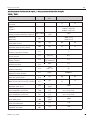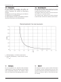
1
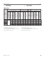
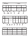
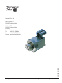
®
®
Präzision
Precision
Montage- und Inbetriebnahmeanleitung
Assembly and Installation Instructions
AC-Servoantriebe FPA
FPA Series AC Servo Actuators
Harmonic Drive AG
900109
02/2005
Harmonic Drive AG
FPA
Contents
Inhalt
1.
2.
3.
Systemübersicht
Bestellbezeichnungen
Allgemeine Sicherheits- und Inbetriebnahmehinweise
3.1 Gefahr
3.2 Bestimmungsgemäße Verwendung
3.3 Herstellererklärung
4. Arbeitsweise und Aufbau
5. Betrieb
5.1 Transport, Lagerung
5.2 Aufstellung
5.3 Elektrischer Anschluss
5.4 Schutz gegen Korrosion und das Eindringen
von Flüssigkeiten und festen Fremdkörpern
6. Anschlussbelegung
6.1 Leistungsanschluss
6.2 Resolveranschluss
6.3 Encoderanschluss
6.4 Multiturn absolut Encoderanschluss
6.5 Anschluss der Haltebremse
6.6 Anschlusskabel
6.6.1 Anschlusskabel für FPA-L-RES Version an
SC-610
6.6.2 Anschlusskabel für FPA-H-Version
7. Antriebsparametrierung für Simodrive
611D/U und Simovert Masterdrives MC
8. Antriebsparametrierung für SC-610
9. Inbetriebnahme
10. Überlastschutz
10.1 Technische Daten PTC 111-K13-140°C
10.2 Technische Daten KTY 84-130
10.3 Überlastdauer
11. Entsorgung
12. Anschlusskabel
12.1 Anschlussbeschreibung
FPA-L-RES an SC-610
12.2 Anschlussbeschreibung
FPA-L-M2048 an SC-610
12.3 Anschlussbeschreibung
FPA-H-RES an Fremdregler
12.4 Anschlussbeschreibung
FPA-H-E2048 an Fremdregler
12.5 Anschlussbeschreibung
FPA-H-M2048 an Fremdregler
2
3
4
5
5
6
7
7
8
8
8
10
11
12
12
13
13
13
14
14
14
15
16
29
30
31
31
32
33
33
30
34
36
38
40
42
1.
2.
3.
3.1
3.2
3.3
4.
5.
5.1
5.2
5.3
5.4
System overview
Ordering code
Safety and operating instructions
3
4
5
Warning
Intended use
Declaration of conformity
Mode of operation and construction
Operation
Transportation, storage
Installation
Electrical connections
Protection against corrosion and penetration
of liquids and debris
6. Wiring diagram
6.1 Power connection
6.2 Resolver connector
6.3 Encoder connector
6.4 Multiturn absolute encoder connector
6.5 Brake connection
6.6 Connecting cable
6.6.1 Connecting cables for FPA-L-RES version and
SC-610 series controllers
6.6.2 Connecting cables for FPA-H-version
7. Drive parameter settings for Simodrive
611D/U and Simovert Masterdrives MC
8. Drive parameter settings for SC-610
9. Commissioning
10. Overload protection
10.1 Technical Data PTC 111-K13-140°C
10.2 Technical Data KTY 84-130
10.3 Overload Duration
11. Disposal
12. Connecting cables
12.1 Wiring diagram
FPA-L-RES with SC-610
12.2 Wiring diagram
FPA-L-M2048 with SC-610
12.3 Wiring diagram
FPA-H-RES with third party controllers
12.4 Wiring diagram
FPA-H-E2048 with third party controllers
12.5 Wiring diagram
FPA-H-M2048 with third party controllers
5
6
7
7
8
8
8
10
11
12
12
13
13
13
14
14
14
15
16
29
30
31
31
32
33
33
31
35
37
39
41
43
900109 02/2005
Harmonic Drive AG
1.
FPA
1.
Systemübersicht
System overview
Tabelle 1 / Table 1
FPA-14-L
FPA-14-H
FPA-20(B)-L
FPA-20(B)-H
FPA-32(B)-L
FPA-32(B)-H
1)
2)
Netzfilter
Line filter
Anschlusskabel
Connecting cable
Regeneratiosnwiderstand
Regeneration resistor
Zubehör
Accessoires
Servoregler SC-610
Servo controllers SC-610
Option
Option
Bremse
Brake
RES (Resolver)
M2048 (EQN 1325) 2)
E2048 (ERN 1185, 1387) 1)
Motorfeedback System
Motor feedback system
Temperaturfüher
Temperature sensor
PTC-111-K13-140ºC
Temperaturfühler
Temperature sensor
KTY-84-130
Motorwicklung 560 VDC
Motor winding 560 VDC
Motorwicklung 320 VDC
Motor winding 320 VDC
Antrieb
Actuator
Getriebeuntersetzung
Ratio
Grundkonfiguration
Basic configuration
21
33
-
-
-
-
-
Encoderauflösung 2048 I/U A, A, B, B, R, R, C, C, D, D
Encoderauflösung inkrementell: 2048 I/U
Encoderauflösung multiturn absolut: 8192 x 4096 U (EnDat)
(B): Neue Variante mit erhöhter Leistung
900109 02/2005
1)
2)
-
-
-
-
-
Encoder resolution 2048 I/U A, A, B, B, R, R, C, C, D, D
Encoder resolution incremental: 2048 ppr
Encoder resolution multiturn absolute: 8192 x 4096 revs. (EnDat)
(B): New variant with increased power
3
Harmonic Drive AG
2.
FPA
2.
Bestellbezeichnungen
Ordering code
Actuator
Antrieb
Servoantrieb
Servo Actuator
Baugröße
Size
FPA-
14
FPA-
20(B)
Unterstzung
Ratio
Wicklung
Winding
21
L = 320 V DC
33
H = 560 V DC
Motorfeedbacksystem
Motor feedback system
RES = Resolver, 2polig
RES = Resolver, 2 poles
E2048 = ERN 1185 (#14)
= ERN 1387 (#20/32)
M2048 = EQN1325
32(B)
FPA-
FPA - 20(B) - 33
-
Optionen
Options
H
-
RES
B: Bremse,
B: Brake,
24 VDC
24 VDC
-
B
Servo Controller
Servoregler
Typ
Type
Nennstrom
Rated Current
Bauart
Type
Spannungsversorgung
Power Supply
AC-Servoregler
AC ServoControl Unit
610: Digitale Stromregelung, Drehzahlregelung,
Pulsfolgebetrieb und
Lageregelung
A: 230 VAC
610: Dig. current control,
Velocity control,
Pulse Follower and
Position Control
SC - 610 - 5
2: 2,5 Arms
5: 5 Arms
7: 7,5 Arms
-
B: 115 VAC
C: 230 VAC+24 VDC
D: 115 VAC+24 VDC
A
A
Sollwertschnittstelle
Command input
interface
Motorfeedbacksystem
Motor Feedback
System
A: ±10V, Pulse-Follower,
H: Hiperface
Single/
Multiturn
Absolut
Nicht in
Gebrauch
Not in use
A
Handwheel/
4-Bin. Eingänge
/4-Bin. Inputs
B: ±10V, Pulse-Follower,
Handwheel/
8-Bin. Eingänge
/8-Bin. Inputs
A
Motorfeedbacksystem
4
R: Resolver
D: EnDat
H
Motor feedback system
Bestelltext
Order code
Typ
Type
Signal
Signal
Auflösung
Resolution
Herstellerbezeichnung
Designation of Manufacturer
RES
2-poliger Resolver
2-poles Resolver
E2048
Inkrementeller Encoder
Incremental Encoder
Sinus / Cosinus 1Vss
Sine / Cosine 1Vpp
2048 [I/U] [I/rpm]
Heidenhain ERN 1185/
ERN 1387
M2048
Multiturn absolut Encoder
Multiturn absolute Encoder
Sinus / Cosinus 1Vss
Sine / Cosine 1Vpp
2048 [I/U] [I/rpm]
EnDat 8192 x 4096 rpm
Heidenhain EQN 1325
900109 02/2005
Harmonic Drive AG
3.
FPA
3.
Allgemeine Sicherheits- und
Inbetriebnahmehinweise
(gemäß Niederspannungsrichtlinie
73/23/EWG)
Safety and operating instructions
(in conformity with the low voltage
directive 73/23/EEC)
Zu beachten sind die Angaben und Anweisungen in
dieser Montage- und Inbetriebnahmeanleitung sowie
im Harmonic Drive Produktkatalog.
Weiterhin
müssen
die
Sicherheitsund
Inbetriebnahmehinweise der Servoregler z. B.
• Harmonic Drive SC-610
• Siemens Simodrive/Simovert
• andere Regler
beachtet werden.
All information and instructions contained in the
Assembly and Installation instructions or Harmonic
Drive product catalogue must be observed.
Furthermore the safety and operating instructions of
the servo controller e. g.
• Harmonic Drive SC-610
• Siemens Simodrive/Simovert
• other controllers
must be observed.
Sonderausführungen können in technischen Details
von den nachfolgenden Ausführungen abweichen!
Bei eventuellen Unklarheiten wird dringend empfohlen, unter Angabe von Typbezeichnung und
Seriennummer beim Hersteller anzufragen.
The technical specification of special versions may differ from those described herein! If you have any
doubts whatsoever, we strongly advise that you consult the manufacturer, giving details of type designation and serial number.
3.1 Gefahr
Elektrische Motoren haben gefährliche, spannungsführende und rotierende Teile sowie möglicherweise
heiße Oberflächen. Alle Arbeiten: Anschluss,
Inbetriebnahme und Instandhaltung sind von qualifiziertem Fachpersonal auszuführen (VDE 0105; IEC
364 beachten).
3.1 Warning
During operation electric motors have hazardous, live
and rotating parts, and possibly also hot surfaces. All
operations concerning connection, commissioning
and regular maintenance are to be carried out by qualified, responsible technical personnel. (Observe VDE
0105; IEC 364).
Vor Beginn jeder Arbeit, besonders aber vor dem Öffnen von Abdeckungen, muss der Servoantrieb vorschriftsmäßig freigeschaltet sein. Neben den
Hauptstromkreisen ist dabei auch auf eventuell vorhandene Zusatz- oder Hilfsstromkreise zu achten!
Before carrying out any work on the motor or unit,
a n d e s p e c i a ll y b e f or e u n c o ve r i n g l iv e p a r t s , d i s connect the motor from the power supply. Remember
to disconnect any supplementary or auxiliary circuits
as well as the main circuits.
900109 02/2005
!
5
Harmonic Drive AG
FPA
Die üblichen „5 Sicherheitsregeln“ lauten nach DIN
VDE 0105:
Freischalten
Gegen Wiedereinschalten sichern
Spannungsfreiheit feststellen
Erden und Kurzschließen
Benachbarte unter Spannung stehende
Teile abdecken oder abschranken
The standard „5 safety rules“ according to DIN VDE
0105 apply.
Disconnect from the power supply
Secure against reconnection
Check that equipment is dead
Earth and short-circuit
Cover or screen off all live adjacent parts
Diese zuvor genannten Maßnahmen dürfen erst dann
zurückgenommen werden, wenn die Instandhaltungsarbeiten abgeschlossen sind und der Servoantrieb
vollständig montiert ist.
Unsachgemäßes Verhalten kann Personen- und
Sachschäden verursachen. Die jeweils geltenden nationalen, örtlichen und anlagespezifischen Bestimmungen und
Erfordernisse sind zu berücksichtigen.
The above actions may only be reversed when all
repair work has been completed and the motor has
been completely reassembled.
Improper conduct can cause severe injury and damage to property. The applicable national, local and
plant-specific specifications and codes of conduct
must be complied with.
3.2
3.2.
Intended use
FPA-Servoactuators are intended for use in
industrial and commercial installations. They
comply with the harmonized standards of the
series EN60034 (VDE 0530). Their use in areas
exposed to explosion hazard is prohibited. In special cases - where these motors are used in a nonindustrial environment - extra safety precautions
(such as touch protection for children) must be provided by the owner or user of the equipment during
installation.
The motors are rated for ambient temperatures from
0°C to 40°C and for installation at altitudes of
≤ 1000 m above sea level.
Plant and machines equipped with converter-fed lowvoltage three-phase motors must satisfy the requirements of the EMC directive 89/336/EEC.
Proper installation is the responsibility of the plant
installer. Signal and power cables should be twisted
and shielded.
They should be laid at least 20 cm apart from one
another and as close as possible to earthed parts.
Bestimmungsgemäße Verwendung
Die FPA-Servoantriebe sind für industrielle oder gewerbliche Anlagen
bestimmt. Sie entsprechen den harmonisierten Normen der Reihe EN60034 (VDE
0530). Der Einsatz im Ex-Bereich ist verboten. Wenn im Sonderfall - bei Einsatz in nicht
gewerblichen Anlagen - erhöhte Anforderungen
gestellt werden (z. B. Berührungsschutz gegen
Kinderfinger), sind diese Bedingungen bei der
Aufstellung anlagenseitig zu gewährleisten.
Die Servomotore sind für Umgebungstemperaturen
von 0°C bis +40°C sowie Aufstellungshöhen ≤ 1000
m über NN ausgelegt.
Anlagen und Maschinen mit umrichtergespeisten
Niederspannungs-Drehstrommotoren müssen den
der
EMV-Richtlinie
Schutzanforderungen
89/336/EWG genügen.
Die Durchführung der sachgerechten Installation
liegt in der Verantwortung des Anlageerrichters.
Signal- und Leistungsleitungen sind verdrillt und
geschirmt auszuführen. Weiterhin sollen sie in mindestens 20 cm Abstand voneinander und möglichst
nahe an geerdeten Teilen verlegt werden.
6
900109 02/2005
Harmonic Drive AG
FPA
Die EMV-Hinweise im Anhang A des
Bedienerhandbuches der Harmonic Drive Servoregler
SC-610 sind zu beachten! Bei Anwendungen mit
Reglern anderer Fabrikate sind die EMV-Hinweise des
jeweiligen Herstellers zu beachten.
Please pay attention to appendix A of the operating
manual of the Harmonic Drive SC-610 servo controllers. In the event that a controller from another manufacturer is used, the corresponding EMC-guidelines of
the manufacturer have to be followed carefully.
3.3
3.3
Herstellererklärung
Declaration of conformity
FPA-Servoantriebe sind Komponenten zum Einbau in
Maschinen im Sinne der Maschinenrichtlinie
89/392/EWG. Die Inbetriebnahme ist solange
untersagt, bis die Konformität des Endproduktes mit
dieser Richtlinie festgestellt ist.
FPA-Servo Actuators are components for installation
in machines as defined by the machine directive
89/392/EEC. Commissioning is prohibited until
such time as the end product has been proved to
conform to the provisions of this directive.
4.
4.
Arbeitsweise und Aufbau
Mode of operation and construction
Die FPA-Servoantriebe sind dauermagneterregte
Drehstrom-Synchron-Antriebe mit integriertem
Präzisionsgetriebe das nach dem Harmonic Planeten
Prinzip arbeitet. Sie sind zum Betrieb an Pulswechselrichtern nach dem Sinusstromprinzip ausgelegt und
zeichnen sich durch hohe Dynamik und einen großen
Drehzahlstellbereich aus.
The FPA-servoactuators are permanent field threephase AC-synchronous actuators with an integrated
precision Harmonic Planetary gear. They are suitable
for operation with pulse-width-modulation inverters
according to the sinusoidal current principle. They are
characterised by good dynamic perfomance and a
wide controlled speed range.
Zum Schutz gegen Übertemperatur ist in die
Ständerwicklung ein Temperatursensor integriert.
Das eingebaute Gebersystem dient zur Lage- und
Drehzahlerkennung des Motors und kann auch als
Lagegeber für die CNC-Steuerung eingesetzt werden.
Optional kann der Servoantrieb mit einer Ruhestromhaltebremse ausgestattet werden.
There is a temperature sensor incorporated in the
three phase motor stator winding, which acts as a
motor protector.
The integrated sensor system serves for detection of
the rotor position and motor speed and can also be
used as a position sensor for NC control.
As an option it is possible to order the FFA-servoactuator with an fail-safe holding brake.
900109 02/2005
7
Harmonic Drive AG
5.
FPA
5.
Betrieb
Operation
5.1 Transport, Lagerung
Wird der FPA-Servoantrieb nach der Auslieferung
nicht gleich in Betrieb genommen, so ist er in einem
trockenen, staub- und erschütterungsfreien Raum zu
lagern.
Lagertemperatur -20°C bis 60°C
Luftfeuchtigkeit 10 bis 80%
5.1 Transportation, storage
If a FPA-servo actuator is not put into service immediately on receipt, it should be stored in a dry and
dust-free area where it will not be subjected to shocks.
5.2
5.2
Storage temperature -20°C to 60°C
Storage humidity 10 to 80%
Aufstellung
Schutzart IP65 (bei korrekter Montage) beachten
und Übereinstimmung mit den Verhältnissen am
Einbauort prüfen!
Die Montage des FPA-Servoantriebes muss ohne
Schläge und Druck auf Abtriebsflansch oder
Sensorgehäuse erfolgen.
Installation
Take note of the information regarding type of
construction and degree of protection IP 65 (for
correct assembly) and check that these
specifications match the site conditions!
Never strike or exert pressure on the output bearing or the sensor housing when installing the
FPA-servo actuator.
Der Anbau muss so erfolgen, dass eine ausreichende Ableitung der Verlustwärme gewährleistet
ist.
The servoactuator must be fitted in such a way
that heat loss can be adequately dissipated.
Die Montageflansche der FPA-Servoantriebe sind
für Innensechskantschrauben Festigkeitsklasse
12.9 ausgelegt.
The mounting flange of the FPA-servo actuator is
designed for hexagonal socket head bolts
strength class 12.9.
Der Abtriebsflansch der FPA-Servobaureihe zur
Befestigung der anzutreibenden Last ist für
Innensechskantschrauben der Festigkeitsklasse
12.9 ausgelegt.
The output flange of the FPA-servo actuator to fix
the load is designed for hexagonal socket head
bolts strength class 12.9.
Die erforderlichen Angaben zur Gehäuse- und
Lastbefestigung sind in der folgenden Tabelle 1 dargestellt.
The data necessary for mounting the actuator in a
housing and for connecting the load to the actuator
are given in table 1.
!
Die in Tabelle 1 angegebene Gewindebohrung der
Gehäusebefestigung beachten.
8
Take attention to the thread bore dimension of the
housing assembly given in table 1.
900109 02/2005
Harmonic Drive AG
FPA
Tabelle / Table 2
Antrieb
Actuator
Gehäusebefestigung mit Schrauben der Qualität 8.8
Housing Assembly with Screws of Quality 8.8
Abtriebsflansch mit Schrauben der Qualität 12.9
Load Assembly with Screws of Quality 12.9
Größe
Size
Gewindebohrungen
Thread Bores
Anzugsmoment [Nm]
Tightening Torque [Nm]
Gewindebohrungen
Thread Bores
Anzugsmoment [Nm]
Tightening Torque [Nm]
FPA-14
FPA-20(B)
FPA-32(B)
4 x M5 x 10
4 x M8 x 14
4 x M10 x 16
5,90
24,60
48,00
6 x M4 x 7
6 x M6 x 10
6 x M8 x 12
5,10
17,40
42,20
Bitte beachten Sie:
Please note:
Alle Angaben sind nur gültig für vollständig entfettete
Anschlussflächen (Reibungskoeffizient µk=0,15). Es wird
empfohlen Loctite 243 zur Schraubensicherung und
Abdichtung zu verwenden.
The above data is only valid for properly cleaned connecting surfaces (friction coefficient µk=0.15). It is recommended to use Loctite 243 for screw locking and sealing.
Abtriebsflansch mit Gewindebohrungen für
Lastbefestigung
Output flange with tapped holes for
load assembly
Gehäuseflansch mit Gewindebohrungen
für Antriebsbefestigung
Housing flange with thread bores for attaching
the actuator to the machine housing
900109 02/2005
9
Harmonic Drive AG
FPA
Vorsicht Verbrennungsgefahr!
Caution: Fire hazard!
An den Servoantrieben können hohe Oberflächentemperaturen von bis zu 80°C auftreten. Es dürfen keine
temperaturempfindlichen Teile, wie z. B. Leitungen
oder elektronische Bauteile, anliegen oder befestigt
werden. Bei Bedarf Berührungsschutzmaßnahmen
vorsehen!
Mit Rücksicht auf einwandfreie Funktion und
lange Lebensdauer sollten nachfolgende
Grenzwerte nicht überschritten werden.
Vibration:
2,5g, 10-400 Hz
Schock:
30g, 11ms
The surfaces of the servoactuators can reach temperatures of over 80°C. No temperature-sensitive items
such as wires or electronic components should be touching or attached to these surfaces. If necessary, take
precautions to prevent contact!
!
With a view to correct functioning of the motor
and long bearing life the following vibration
values must not be exceeded.
Vibration:
2,5g, 10-400 Hz
Shock:
30g, 11ms
5.3 Elektrischer Anschluss
Alle Arbeiten nur im spannungslosen
Zustand der Anlage vornehmen. Wegen der
eingebauten Dauermagnete liegt bei rotierendem Läufer an den Motoranschlüssen Spannung
an.
5.3
Electrical connections
The system must be disconnected from the
power supply before any maintenance is carried out! Due to the fact that the motors contain permanent magnets, a voltage is generated
at the motor terminals when the rotor is turned.
Beim Anschließen des Servoantriebes ist zu beachten,
dass,
die Anschlussleitungen den Umgebungsbedingungen, Stromstärken, den auftretenden
Spannungen und mechanischen Anforderungen
angepasst sind,
der Schutzleiter an PE angeschlossen wird,
alle Kabel geschirmt, das Signalkabel zusätzlich
paarig verseilt ist.
For the connection of the servo actuator please ensure that,
the connecting leads should be suitable for the
type of use, as well as the voltages and amperages concerned.
the protective earth must be connected to the terminal marked PE.
all cables used should be provided with a shield
and in addition the encoder cable should feature
twisted pair leads.
10
900109 02/2005
Harmonic Drive AG
5.4
FPA
5.4
Schutz gegen Korrosion und das
Eindringen von Flüssigkeiten und festen
Fremdkörpern
Protection against corrosion and penetration
of liquids and debris
Material Getriebegehäuse:
Aluminium und Wälzlagerstahl
Oberfläche: Korrosionsgeschützt
Material of gear housing:
Aluminium and Roller bearing steel
Surface: Corrosion protected
Material Motorgehäuse: Aluminium
Oberfläche: schwarz lackiert (RAL 9005)
Material of motor housing: Aluminium
Surface: Black painted (RAL 9005)
Das Standardprodukt erreicht bei gesteckten Anschlusssteckern die Schutzart IP65,
wenn durch die Umgebungsbedingungen
(Flüssigkeiten, Gase, Taubildung) keine
Korrosion an der Lauffläche der
Radialwellendichtung hervorgerufen wird.
Die
Flanschschrauben
sind
mit
Schraubensicherung (z. B. Loctite 243) zu
dichten.
Scharfkantige oder abrasiv wirkende Teile
(Späne, Splitter, Staub aus Metall,
Mineralien usw.) dürfen nicht mit
Radialwellendichtungen in Kontakt kommen.
Ein permanent auf der Radialwellendichtung stehender Flüssigkeitsfilm sollte verhindert werden.
Hintergrund: Bei vollständig abgedichtetem Servoantrieb entstehen infolge wechselnder Betriebstemperaturen Druckdifferenzen im Servoantrieb, die zum
Einsaugen der auf der Wellendichtung stehenden Flüssigkeit führen können.
Gegenmaßnahme: Ggf. eine zusätzliche,
kundenseitige Wellendichtung oder
Sperrluftanschluss (konstanter Überdruck
im Servoantrieb mit getrockneter, gefilterter Luft, max. 104Pa).
Bitte Rücksprache mit Harmonic Drive AG.
900109 02/2005
X
X
X
X
The standard product provides protection class IP 65 under the provision that
the connectors are correctly attached
and corrosion from the ambient atmosphere (condensation, liquids or gases)
at the running surface of the output
shaft seal is prevented. All flange screws must be sealed with an appropriate
sealant e.g. Loctite 243. Contact between sharp-edged or abrasive objects
(cutting chips, splinters, metallic or
mineral dust etc.) and the output shaft
seal must be prevented. In addition, permanent contact between the output
shaft seal and a permanent liquid covering should be prevented. Please note
that the changing operating temperature of a completely sealed actuator can
lead to a pressure differential between
the environment and the inside of the
actuator. This can cause liquid covering
the output shaft seal to be drawn into
the actuators housing, which can lead
to corrosive damage. As a countermeasure we recommend the use of an additional shaft seal (to be provided by the
user) or the maintenance of a constant
pressure inside the actuator by applying
dry filtered air at a pressure of not more
than 104 Pa. Please contact Harmonic
Drive AG for further advice.
11
Harmonic Drive AG
6.
FPA
6.
Anschlussbelegung
Wiring diagram
Following versions are available!
Nachfolgende Varianten sind verfügbar!
Wicklung / Winding
Motorfeedback
Version
Resolver
Encoder (ERN)
Mutiturn Encoder (EQN)
320 VDC
560 VDC
FPA-L
FPA-H
Die FPA-L-Variante ist zum Betrieb an den von
Harmonic Drive gelieferten SC-610 geeignet, während
die FPA-H-Variante zum Betrieb an Simodrive 611U/D
bzw. Simovert Masterdrive MC geeignet ist.
The FPA-L version is suitable for operation with the
SC-610 drivers supplied by Harmonic Drive. The FPAH version is suitable for operation with the Simodrive
611U/D or Simovert Masterdrive MC.
6.1 Leistungsanschluss
Leistungs- und Bremsenanschluss erfolgen über den
Leistungsstecker. Ein direkter Anschluss an das
Drehstromnetz ist nicht erlaubt und führt zur
Zerstörung des Servomotors.
6.1 Power connection
The power and brake connections are provided via the
power connector. Direct connection to the threephase AC supply is not allowed and will lead to the
destruction of the motor.
Auf richtige Phasenfolge ist zu achten!
Der Servoantrieb darf nur mit einem leistungsmäßig
abgestimmten Pulswechselrichter betrieben werden.
12
!
Check for correct phase sequence!
The FHA-servo actuator may only be operated from a
properly matched pulse-width-modulation inverter.
900109 02/2005
Harmonic Drive AG
FPA
6.2
Resolveranschluss
6.2
Resolver connector
6.3
Encoderanschluss
6.3
Incremental encoder connector
6.4
Multiturn absolut Encoderanschluss
6.4
Multiturn absolute encoder connector
P-Encoder = +Up
M-Encoder = GND
900109 02/2005
13
Harmonic Drive AG
FPA
6.5 Anschluss der Haltebremse
Der Anschluss der Haltebremse erfolgt über das
Motorkabel. Die Dauermagnet-Haltebremse arbeitet
nach dem Ruhestromprinzip. Sie öffnet bei Anlegen
einer Gleichspannung von 24V ± 10%. Die Spannung
muss innerhalb des angegebenen Toleranzbereichs
liegen, da sonst die Betriebssicherheit gefährdet ist.
Bei eingeschaltetem Motor muss die Bremse immer
geöffnet sein. Beim Ausschalten der Bremse oder bei
Stromausfall wird die Bremsennabe vom Magnetkörper angezogen und dadurch die Motorwelle festgehalten.
6.5 Brake connection
The brake is connected via the motor cable. The failsafe permanent-magnet holding brake operates according to the closed-circuit principle. It is released when
a current of 24 V DC ± 10% is applied. The voltage
must be between the specified tolerance limits, otherwise reliable operation cannot be guaranteed. When
the motor is switched on, the brake must always be
opened. When the brake is closed or if there is a
power failure, the brake hub is pulled towards the
magnet, thus preventing the motor shaft from
moving.
Die Bremse ist nur für eine begrenzte Anzahl von
Notbremsungen ausgelegt. Der Einsatz als Arbeitsbremse ist nicht zulässig.
The brake is only designed to carry out a limited number of emergency braking operations. It must not be
used as a regular service brake.
6.6 Anschlusskabel
Für alle AC-Servoantriebe der Baureihe FPA müssen
geschirmte
Leitungen
eingesetzt
werden.
Vorkonfektionierte Leitungen bieten gegenüber eigenkonfektionierten Leitungen viele Vorteile. Neben der
Sicherheit der einwandfreien Funktion und der hohen
Qualität bieten sie auch Kostenvorteile.
6.6 Connecting cables
It is necessary to use shielded cables for all FPA-series
AC-Servo-Actuator. Pre-assembled cables offer many
benefits compared to self-made cables. Beside ensuring flawless operation and high quality, they are also
less expensive. The use of pre-assembled cables can
cut the cost of logistics, design, assembly and purchasing.
6.6.1 Anschlusskabel für FPA-L Version an SC-610
Zum Betrieb der FPA-Servoantriebe sind Anschlusskabel in PUR-Ausführung in nachfolgender Konfiguration verfügbar. Die Anschlusskabelsätze beinhalten
das Motorkabel und das Resolverkabel bzw. EnDatKabel, die steckerfertig zum Anschluss an SC-610 vorkonfektioniert sind.
6.6.1 Connecting cables for FPA-L version and
SC-610-series Controllers
Connecting cables with PUR-cover for operation of
FPA-series actuators are available in following configuration: Connecting cable sets contain motor cable
and resolver or EnDat cable which are prepared for
direct connection at the SC-610.
HD-T.-Nr./HD-Part-No.
EnDat
HD-T.-Nr./HD-Part-No.
Resolver
Standardlängen/Standard lengths
306681
602617
5m
306682
602618
10m
306683
602619
15m
Die genaue Anschlussbelegung ist im Kapitel 12 dargestellt.
14
The cable connection is shown in chapter 12.
900109 02/2005
Harmonic Drive AG
FPA
6.6.2 Anschlusskabel für FPA-H-Version
Die verwendeten Stecker sind kompatibel zur
Motorenbaureihe 1FT6xxx der Siemens AG. Durch
Verwendung von Anschluss-Steckern werden
Verdrahtungsfehler ausgeschlossen und der
Verdrahtungsaufwand minimiert. Zur Verlängerung
der Motor- und Resolver-/Encoderanschlussleitungen
können die vorkonfektionierten Anschlusskabel der
Siemens AG oder eigengefertigte Anschlusskabel verwendet werden. Alle Kabel müssen geschirmt, das
Encoderkabel muss zusätzlich paarig verseilt sein.
6.6.2 Connecting cables for FPA-H-version
The connectors are compatible with Siemens AG
motors of the 1FT6xxx series. Using these connectors
ensures that the wiring will be correct and can be carried out easily.
For cable extensions of the motor and resolver/encoder cable it is possible to use extension cables from
Siemens AG or self-made extensions.
All cables used should feature a cable shield. The
cable used for the encoder should also feature additionally twisted pair leads.
Signalgeberanschluss
Signal connection
Motorfeedbacksystem
Reglertyp
Amplifier Type
Kabelverlängerung
Cable extension
Resolver
611U/Masterdrive MC
6FX-8002-2CF02-1XXO
Inkr. Encoder
Incr. Encoder
611U/611D/Masterdrive MC
6FX-8002-2CA31-1XXO
Absolut Encoder
Absolute Encoder
611U/611D/Masterdrive MC
6FX-8002-2EQ1O-1XXO
Power connection
Leistungsanschluss
Steckergröße
Connector Size
Reglertyp
Amplifier type
611U/611D
1
Masterdrive MC
Vorkonfektionierte Anschlusskabel für Antriebsregler
anderer Hersteller sind in Kapitel 12.3-12.5 dargstellt.
900109 02/2005
Kabelverlängerung
Cable extension
Bremse
Brake
6FX-8002-5CA01-1XXO
6FX-8002-5DA01-1XXO
6FX-8008-1AB01-1XXO
6FX-8008-1AA01-1XXO
Connecting cables for third party servo controllers are
given in chapter 12.3-12.5.
15
Harmonic Drive AG
7.
FPA
7.
Antriebsparametrierung für Simodrive
611D/U und Simovert Masterdrives MC
Drive parameter settings for Simodrive
611D/U and Simovert Masterdrives MC
Zur Positions-, Drehzahl- u. Stromregelung mit dem
Umrichtersystem Simodrive/Simovert ist es erforderlich, die antriebsspezifischen Motordaten des eingesetzten FPA-Servoantriebes nach Tabelle 3-8 als
Fremdmotordaten bereitzustellen.
For the position control, speed control and current
control loop of the Simodrive/Simovert converter
system it is necessary to set the drive parameters
according to Tables 3-8 for the FPA servo system.
Achtung!
Bitte nehmen Sie zur Antriebsparametrierung die ent sprechende „Inbetriebnahmedokumentation“ der
Siemens AG zur Hand.
Attention!
Please pay special attention to the Sinumerik and
Simodrive start up documentation from Siemens AG.
Antriebsparametrierung mit 810D/840D
Zur Eingabe der antriebsspezifischen Motordaten
eines FPA mit Inkrementellem Encoder ERN über die
Flachbedientafel OP031 geht man wie folgt vor:
A: Bildschirm
B: Alpha-/Numerikblock
C: Cursorblock
D: Maschinensteuertafel
1: Maschinenbereichstaste
2: Recall (Rücksprung)
3: Softkeyleiste (horizontal)
4: Taste etc. (Menüerweiterung)
5: Bereichsumschalttaste
6: Softkeyleiste (vertikal)
16
!
Drive parameter settings with 810/840D
To set the Drive parameter settings of a FPA with
incremental Encoder ERN with the slimline operator
panel OP031 please use the following procedure:
Monitor
Alpha/numeric keyboard
Cursor keyboard
Operator panel
Machine area key
Recall
Softkey bar (horizontal)
ETC-key (Menu extension)
Area changeover key
Softkey bar (vertical)
900109 02/2005
Harmonic Drive AG
FPA
Durch Drücken der <Bereichsumschalttaste> werden
im Grundmenü auf der horizontalen Softkeyleiste die
Bedienerbereiche eingeblendet. Davon sind auszuwählen:
• <Inbetriebnahme>
• <Maschinendaten> und
• <VSA>.
Auf der vertikalen Softkeyleiste sind auszuwählen:
• <Motor/Regler> und
• <Motorauswahl>.
After pressing the „Area changeover key“ you can see
several kinds of operating area at the horizontal softkey bar.
Please select
• <Start up>
• <Machine data>
• <FDD>.
At the vertical softkey bar please press
• <Motor/Controller> and
• <Motor selection>
a) CNC-Softwareversion 3.x
Für den CNC-Softwarestand 3.X sind die Daten in der
Bildschirmanzeige wie folgt zu ändern:
Gebertyp:
„Inkrementeller Geber“
„2048“
Geberstrichzahl:
Motor:
„Fremdmotor“
Mit der <Eingabe>-Taste bestätigen.
a) CNC-Software version 3.x
For the CNC-Software version 3.x change the values
given on the screen as follows.
Encoder type:
„incremental encoder“
No. of enc. marks: „2048“
Motor:
„non Siemens mot.“
Confirm with the <ENTER> key.
Zur Eingabe der Motordaten die Taste
• <Fremdmotordaten>
auf der vertikalen Softkeyleiste wählen und die
antriebsspezifischen Motordaten nach Tabelle 3-8 eingeben.
Zur Übernahme der Daten
• <O.K.>-Taste drücken und nochmals
• <O.K.>Taste drücken.
For the drive parameter setting please select
• „Non-Siem. motor data“
on the vertical softkey bar and set the drive parameters given in table 3-8.
Close with
• <O.K.> and
• <O.K.>
b) CNC-Softwareversion 4.x
Ab CNC-Softwarestand 4.x wird durch Drücken der
Softkeyleiste
• <Fremdmotor>
ein Eingabemenü geöffnet, das die Eingabe der
antriebsspezifischen Motordaten nach Tabelle 3-8
ermöglicht.
Zur Übernahme der Daten
• <O.K.-Taste>“ drücken.
Am Bildschirm erscheint ein Eingabemenü zur
Eingabe der folgenden Messsystemspezifischen
Daten.
b) CNC-Software version 4.x
For the CNC-Software version 4.x press on the vertical
softkey bar
• <Non Siemens mot.>
an input menu will be open to set the drive parameters given in table 3-8.
Close with • <O.K>.“
Rotatorisches Mess-System:
„Inkrementeller Geber mit Nullmarke“
Grobsynchronisation: „C/D-Spur“
Drehzahlistwertinvertierung: „nein“
Geberstrichzahl: „2048“
Zur Übernahme der Daten
• <O.K.>-Taste“ drücken.
900109 02/2005
For the measuring system please change the values
given on the screen as follows.
Rotary measuring system:
„Incremental with zero mark“
Coarse synchronization with: „C/D-Track“
Speed actual value inversion: „No“
No. of enc. marks:
„2048“
Close with
• <O. K>.
17
Harmonic Drive AG
FPA
c) Softwareversion 3.x und 4.x
Die weitere Vorgehensweise ist unabhängig von der
Softwareversion der CNC-Steuerung. Zur Ermittlung
der Regelungsfaktoren des Strom- und Drehzahlregelkreises
• <Reglerdaten berechnen> drücken.
c) Software version 3.x and 4.x
The following steps are independent of the software
version. The CNC-control unit will determine the current loop and speed loop parameters after pressing
Die maximal nutzbare Motordrehzahl wird auf Nenndrehzahl * 1,1 begrenzt.
The maximum motor speed is limited to the Rated
speed * 1.1.
Attention!
The temperature specific values are
- Motor Temp. warning (1602) 120°
- Motor Temp. shut down (1607) 140°
are set via the „FDD“ area.
Achtung!
Die temperaturspezifischen Antriebsdaten
- Motor Temp Warnung (1602) 120°C
- Motor Temp Abschaltung (1607) 140°C
werden im Bereich „VSA“ eingegeben.
• <calculate contr. data>
!
Der maximale Motorstrom bzw. Motorgrenzstrom
(611U) muss zeitlich auf 200ms begrenzt werden!
The maximum motor current and motor current limit
(611U) must be limited to 200ms!
Nach Eingabe aller Daten auf der vertikalen
Softkeyleiste
• <Bootfile>
• <Bootfile sichern>
aktuelles Menü mit der <Recall>-Taste verlassen
• <NCK-Reset> über Softkeyleiste oder <Reset>
Taste ausführen.
After setting up the drive parameters please press on
the vertical softkey bar
• <Boot file>
• <Save boot file>
Quit the current menu with the <Recall> button
• <NCK-Reset> via softkey bar or press the
<Reset> button
to save and activate the parameters.
Die eingegebenen Motordaten sind jetzt aktiv. Stromund Drehzahlregler sind konfiguriert. Abhängig von
der Anwendung müssen der Drehzahlregler und die
Beschleunigungswerte, sowie der Kv-Faktor nachoptimiert werden.
Nach Eingabe der „VSA“-Daten müssen achsspezifische Anwendungsdaten eingegeben werden, wie z. B.:
After you finish your set up, the current control and
speed control loop is configured. According to the
application it is necessary to optimize the speed loop
parameters, the acceleration values and also the
Kv-Gain.
During your commissioning procedure it is also necessary to set the axis specific machine data, e. g.:
Tabelle / Table 3
MD-No.
MD-Name
31020
ENC_RESOL
31060
32000
DRIVE_ENC_RATIO
NUMERIA
MAX_AX_VELO
32010
JOG_VELO_RAPID
32020
JOG_VELO
Kommentar/Comment
Sppezifikation/ Specification
Einheit/ Dimension
1024
[I/U]
[I/rev]
_
Encoder-Auflösung
Encoder resolution
Zähler Lastgetriebe
Nominator load gearing
Maximale Achsgeschwindigkeit
Maximum axis velocity
Konventioneller Eilgang
Conventional rapid traverse
Konventionelle Achsgeschw.
Conventional axis velocity
Standard = 1
Nenndrehzahl
Rated speed
_
POSCTRL_GAIN
Kv-Faktor
Kv-factor
32300
MAX_AX_ACCEL
Achsbeschleunigung
Axis acceleration
36200
AX_VELO_LIMIT
Geschwindigkeitsüberwachung
Velocity control
18
_
_
Kv =
32200
_
_
Geschwindigkeit
Schleppabstand
[m/min]
Velocity
Kv =
Following error
α=
T
[U/s2]
max
J
2
π
ges * *
Maximale Drehzahl
Maximum speed
or 16,66 [1/s]
[mm]
[m/s2] or [U/s2]
[min-1]
[rpm]
900109 02/2005
Harmonic Drive AG
FPA
Antriebsparameter für Simodrive 611D/U / Drive parameters for Simodrive 611D/U
Tabelle / Table 4
MD-Name
MD-Nr.:
Einheit
Unit
Getriebeuntersetzung
Gear ratio
21
Geberstrichzahl ERN1387/EQN1325
[I]
1005/31020
[rev]
Encoder resolution ERN1387/EQN1325
Motorcode
1102
Motor code
Motornennstrom
1103
[A]
Rated motor current
Maximaler Motorstrom [200ms]
1104
[A]
Maximum motor current [200ms]
Polpaarzahl Motor
1112
Number of pole pairs of motor
Drehmomentkonstante
1113
[Nm/A]
Torque constant
[V/1000min-1]
Spannungskonstante
1114
[V/1000rpm]
Voltage constant
Ankerwiderstand
Ohm
1115
Armature resistance
Ankerinduktivität
[mH]
1116
„Lstr. x 1,5“
Armature inductance
Motorträgheitsmoment
2
[kgm ]
1117
Moment of inertia of motor
Motorstillstandsstrom
[A]
1118
Motor zero speed current
Motorgrenzstrom (nur 611U) [200ms]
[A]
1122
Motor current limit (611U only) [200ms]
Motormaximaldrehzahl
[min-1]
1146
Maximum motor speed
[rpm]
Untere Stromgrenze Adaption
[%]
1180
Lower adaptation current limit
Obere Stromgrenze Adaption
[%]
1181
Upper adaptation current limit
900109 02/2005
33
RES = 2 pol. Resolver
E2048 = ERN1185
M2048 = EQN1325
Geber 1
Encoder 1
Motornenndrehzahl
Rated motor speed
Warnschwelle Motorüberwachung
Alarm threshold motor
Abschaltgrenze Motor
Shutdown limit motor
FPA-14
2048
2000 (611D)
1999 (611U)
0,8
0,8
2,7
1,6
3
0,55
31,5
33,5
46
0,000026
0,8
0,8
2,7
1,6
6000
0%
(nur / only 611U)
100 %
(nur / only 611U)
1400
[min-1]
[rpm]
3000
1602
[°C]
120
1607
[°C]
140
19
Harmonic Drive AG
FPA
Antriebsparameter für Simodrive 611D/U / Drive parameters for Simodrive 611D/U
Tabelle / Table 5
MD-Name
MD-Nr.:
Einheit
Unit
FPA-20
Getriebeuntersetzung
Gear ratio
21
Geber 1
Encoder 1
RES = 2 pol. Resolver
E2048 = ERN1387
M2048 = EQN1325
Geberstrichzahl ERN1387/EQN1325
[I]
1005/31020
[rev]
Encoder resolution ERN1387/EQN1325
Motorcode
1102
Motor code
Motornennstrom
1103
[A]
Rated motor current
Maximaler Motorstrom [200ms]
1104
[A]
Maximum motor current [200ms]
Polpaarzahl Motor
1112
Number of pole pairs of motor
Drehmomentkonstante
1113
[Nm/A]
Torque constant
[V/1000min-1]
Spannungskonstante
1114
[V/1000rpm]
Voltage constant
Ankerwiderstand
Ohm
1115
Armature resistance
Ankerinduktivität
[mH]
1116
„Lstr.
x 1,5“
Armature inductance
Motorträgheitsmoment
2
[kgm ]
1117
Moment of inertia of motor
Motorstillstandsstrom
[A]
1118
Motor zero speed current
Motorgrenzstrom (nur 611U) [200ms]
[A]
1122
Motor current limit (611U only) [200ms]
Motormaximaldrehzahl
[min-1]
1146
Maximum motor speed
[rpm]
Untere Stromgrenze Adaption
[%]
1180
Lower adaptation current limit
Obere Stromgrenze Adaption
[%]
1181
Upper adaptation current limit
Motornenndrehzahl
[min-1]
1400
Rated motor speed
[rpm]
Warnschwelle Motorüberwachung
[°C]
Alarm threshold motor
1602
Abschaltgrenze Motor
[°C]
1607
Shutdown limit motor
20
33
2048
2000 (611D)
1999 (611U)
1,4
1,4
8,7
8,0
3
0,65
39,5
8,95
27,0
0,000054
1,4
1,4
8,7
8,0
6000
0%
(nur / only 611U)
100 %
(nur / only 611U)
3000
120
140
900109 02/2005
Harmonic Drive AG
FPA
Antriebsparameter für Simodrive 611D/U / Drive parameters for Simodrive 611D/U
Tabelle / Table 6
MD-Name
MD-Nr.:
Einheit
Unit
FPA-20B
Getriebeuntersetzung
Gear ratio
21
Geber 1
Encoder 1
RES = 2 pol. Resolver
E2048 = ERN1387
M2048 = EQN1325
Geberstrichzahl ERN1387/EQN1325
[I]
1005/31020
[rev]
Encoder resolution ERN1387/EQN1325
Motorcode
1102
Motor code
Motornennstrom
1103
[A]
Rated motor current
Maximaler Motorstrom [200ms]
1104
[A]
Maximum motor current [200ms]
Polpaarzahl Motor
1112
Number of pole pairs of motor
Drehmomentkonstante
1113
[Nm/A]
Torque constant
[V/1000min-1]
Spannungskonstante
1114
[V/1000rpm]
Voltage constant
Ankerwiderstand
Ohm
1115
Armature resistance
Ankerinduktivität
[mH]
1116
„Lstr.
x 1,5“
Armature inductance
Motorträgheitsmoment
2
[kgm ]
1117
Moment of inertia of motor
Motorstillstandsstrom
[A]
1118
Motor zero speed current
Motorgrenzstrom (nur 611U) [200ms]
[A]
1122
Motor current limit (611U only) [200ms]
Motormaximaldrehzahl
[min-1]
1146
Maximum motor speed
[rpm]
Untere Stromgrenze Adaption
[%]
1180
Lower adaptation current limit
Obere Stromgrenze Adaption
[%]
1181
Upper adaptation current limit
Motornenndrehzahl
[min-1]
1400
Rated motor speed
[rpm]
Warnschwelle Motorüberwachung
[°C]
Alarm threshold motor
1602
Abschaltgrenze Motor
[°C]
1607
Shutdown limit motor
900109 02/2005
33
2048
2000 (611D)
1999 (611U)
1,3
1,3
7,7
3,8
3
1,08
65
6,7
31,7
0,000128
1,3
1,3
7,7
3,8
6000
0%
(nur / only 611U)
100 %
(nur / only 611U)
3000
120
140
21
Harmonic Drive AG
FPA
Antriebsparameter für Simodrive 611D/U / Drive parameters for Simodrive 611D/U
Tabelle / Table 7
MD-Name
MD-Nr.:
Einheit
Unit
FPA-32
Getriebeuntersetzung
Gear ratio
21
Geber 1
Encoder 1
RES = 2 pol. Resolver
E2048 = ERN1185
M2048 = EQN1325
Geberstrichzahl ERN1387/EQN1325
[I]
1005/31020
[rev]
Encoder resolution ERN1387/EQN1325
Motorcode
1102
Motor code
Motornennstrom
1103
[A]
Rated motor current
Maximaler Motorstrom [200ms]
1104
[A]
Maximum motor current [200ms]
Polpaarzahl Motor
1112
Number of pole pairs of motor
Drehmomentkonstante
1113
[Nm/A]
Torque constant
[V/1000min-1]
Spannungskonstante
1114
[V/1000rpm]
Voltage constant
Ankerwiderstand
Ohm
1115
Armature resistance
Ankerinduktivität
[mH]
1116
„Lstr. x 1,5“
Armature inductance
Motorträgheitsmoment
2
[kgm ]
1117
Moment of inertia of motor
Motorstillstandsstrom
[A]
1118
Motor zero speed current
Motorgrenzstrom (nur 611U) [200ms]
[A]
1122
Motor current limit (611U only) 200ms]
Motormaximaldrehzahl
[min-1]
1146
Maximum motor speed
[rpm]
Untere Stromgrenze Adaption
[%]
1180
Lower adaptation current limit
Obere Stromgrenze Adaption
[%]
1181
Upper adaptation current limit
Motornenndrehzahl
Rated motor speed
Warnschwelle Motorüberwachung
Alarm threshold motor
Abschaltgrenze Motor
Shutdown limit motor
22
1400
[min-1]
[rpm]
1602
[°C]
1607
[°C]
33
2048
2000 (611D)
1999 (611U)
2,8
2,8
11,6
11,6
3
0,79
48
3,5
19,5
0,00025
2,8
2,8
11,6
11,6
4500
0%
(nur / only 611U)
100 %
(nur / only 611U)
2500
120
140
900109 02/2005
Harmonic Drive AG
FPA
Antriebsparameter für Simodrive 611D/U / Drive parameters for Simodrive 611D/U
Tabelle / Table 8
MD-Name
MD-Nr.:
Einheit
Unit
FPA-32B
Getriebeuntersetzung
Gear ratio
21
Geber 1
Encoder 1
RES = 2 pol. Resolver
E2048 = ERN1185
M2048 = EQN1325
Geberstrichzahl ERN1387/EQN1325
[I]
1005/31020
[rev]
Encoder resolution ERN1387/EQN1325
Motorcode
1102
Motor code
Motornennstrom
1103
[A]
Rated motor current
Maximaler Motorstrom [200ms]
1104
[A]
Maximum motor current [200ms]
Polpaarzahl Motor
1112
Number of pole pairs of motor
Drehmomentkonstante
1113
[Nm/A]
Torque constant
[V/1000min-1]
Spannungskonstante
1114
[V/1000rpm]
Voltage constant
Ankerwiderstand
Ohm
1115
Armature resistance
Ankerinduktivität
[mH]
1116
„Lstr. x 1,5“
Armature inductance
Motorträgheitsmoment
2
[kgm ]
1117
Moment of inertia of motor
Motorstillstandsstrom
[A]
1118
Motor zero speed current
Motorgrenzstrom (nur 611U) [200ms]
[A]
1122
Motor current limit (611U only) 200ms]
Motormaximaldrehzahl
[min-1]
1146
Maximum motor speed
[rpm]
Untere Stromgrenze Adaption
[%]
1180
Lower adaptation current limit
Obere Stromgrenze Adaption
[%]
1181
Upper adaptation current limit
Motornenndrehzahl
Rated motor speed
Warnschwelle Motorüberwachung
Alarm threshold motor
Abschaltgrenze Motor
Shutdown limit motor
900109 02/2005
1400
[min-1]
[rpm]
1602
[°C]
1607
[°C]
33
2048
2000 (611D)
1999 (611U)
3,1
2,9
13,2
9,1
3
1,44
87
3,6
26,2
0,000578
3,1
2,9
13,2
9,1
4500
0%
(nur / only 611U)
100 %
(nur / only 611U)
2500
120
140
23
Harmonic Drive AG
Tabelle / Table 9:
FPA
Antriebsparameter für Simovert Masterdrives MC / Drive parameters for Simovert Masterdrives MC
MD-Name
Getriebeuntersetzung
Gear ratio
Menü
Menu
Umrichter Anschluss-Spannung
Amplifier power supply
Motorart
Motor type
Motornennstrom
Rated motor current
Polpaarzahl Motor
Number of pole pairs of motor
Motornenndrehmoment
Rated motor torque
Ankerinduktivität (L-N)
Armature inductance (L-N)
Ankerwiderstand (L-N)
Armature resistance (L-N)
Maximaler Motorstrom [200ms]
Maximum motor current [200ms]
Geber 1
Encoder 1
Temperatursensor
Temperature sensor
Winkel-Offset
Angular offset
Encodersimulation für Resolver
Encoder simulation for resolver
Encoderauflösung
Encoder resolution
Lageregler Kv
Kv position controller
Lageregler Tn
Tn position controller
Drehzahlregler Kp
Kp speed controller
Drehzahlregler Tn
Tn speed controller
Stromregler Kp
Kp current controller
Dynamik Stromregelung
Current controller dynamic
Pulsfrequenz
Pulse frequency
Bezugsstrom
Speed reference
Bezugsspannung
Voltage reference
Bezugsfrequenz
Frequency reference
Bezugsdrehzahl
Speed reference
Bezugsdrehmoment
Torque reference
Max. Drehzahl + Drehrichtung
Max. speed and direction
Max. Drehzahl + Drehrichtung
Max. speed + direction
Warnschwelle Motorüberwachung
Alarm threshold motor
Abschaltgrenze Motor
Shutdown limit motor
24
MD-Nr.:
Einheit
Unit
FPA-14
21
P060
P071
5
[V]
600 V DC
3
P095
P102
33
[A]
0,8
P109
0,8
3
P113
[Nm]
0,3
P120
[mH]
„Lstr. * 1,5“
45,7
P121
[mΩ]
33500
P128
[A]
2,7
1,6
P130
RES = „1“ (2 pol. Resolver),
E2048 = „3“ (Sinus/Cosinus Encoder)
M2048 = „4“ (Multiturn Encoder)
P131
„1“ = KTY 84-130
P132
P134
P136
[°]
0
[Imp./U]
[Pulse/Rev.]
[Imp./U]
[Pulse/Rev.]
„0“ = 512
„1“ = 1024
„11“ = 2048
abhängig von der Anwendung
according to the application
abhängig von der Anwendung
according to the application
abhängig von der Anwendung
according to the application
abhängig von der Anwendung
according to the application
abhängig von der Anwendung
according to the application
„0“ = High: „1“ = Medium
„2“ = Low
P204
P206
P235
P240
P282
P296
05 (10)
P340
[kHz]
P350
[A]
P351
[V]
400,00
P352
[Hz]
400,00
0,8
0,8
-1
P353
[min ]
[rpm]
P354
[Nm]
P452
[%]
100,00
P453
[%]
-100,00
P380
[°C]
120
P381
[°C ]
140
3000
0,6
0,4
900109 02/2005
Harmonic Drive AG
FPA
Tabelle / Table 10: Antriebsparameter für Simovert Masterdrives MC / Drive parameters for Simovert Masterdrives MC
MD-Name
Getriebeuntersetzung
Gear ratio
Menü
Menu
Umrichter Anschluss-Spannung
Amplifier power supply
Motorart
Motor type
Motornennstrom
Rated motor current
Polpaarzahl Motor
Number of pole pairs of motor
Motornenndrehmoment
Rated motor torque
Ankerinduktivität (L-N)
Armature inductance (L-N)
Ankerwiderstand (L-N)
Armature resistance (L-N)
Maximaler Motorstrom [200ms]
Maximum motor current [200ms]
Geber 1
Encoder 1
Temperatursensor
Temperature sensor
Winkel-Offset
Angular offset
Encodersimulation für Resolver
Encoder simulation for resolver
Encoderauflösung
Encoder resolution
Lageregler Kv
Kv position controller
Lageregler Tn
Tn position controller
Drehzahlregler Kp
Kp speed controller
Drehzahlregler Tn
Tn speed controller
Stromregler Kp
Kp current controller
Dynamik Stromregelung
Current controller dynamic
Pulsfrequenz
Pulse frequency
Bezugsstrom
Speed reference
Bezugsspannung
Voltage reference
Bezugsfrequenz
Frequency reference
Bezugsdrehzahl
Speed reference
Bezugsdrehmoment
Torque reference
Max. Drehzahl + Drehrichtung
Max. speed and direction
Max. Drehzahl + Drehrichtung
Max. speed + direction
Warnschwelle Motorüberwachung
Alarm threshold motor
Abschaltgrenze Motor
Shutdown limit motor
900109 02/2005
MD-Nr.:
Einheit
Unit
FPA-20
21
P060
P071
5
[V]
600 V DC
3
P095
P102
33
[A]
1,4
P109
1,4
3
P113
[Nm]
0,9
P120
[mH]
„Lstr. * 1,5“
27,0
P121
[mΩ]
8950
P128
[A]
8,7
8,0
P130
RES = „1“ (2 pol. Resolver),
E2048 = „3“ (Sinus/Cosinus Encoder)
M2048 = „4“ (Multiturn Encoder)
P131
„1“ = KTY 84-130
P132
[°]
0
P134
[Imp./U]
[Pulse/Rev.]
[Imp./U]
[Pulse/Rev.]
„0“ = 512
„1“ = 1024
P136
„11“ = 2048
abhängig von der Anwendung
according to the application
abhängig von der Anwendung
according to the application
abhängig von der Anwendung
according to the application
abhängig von der Anwendung
according to the application
abhängig von der Anwendung
according to the application
„0“ = High: „1“ = Medium
„2“ = Low
P204
P206
P235
P240
P282
P296
05 (10)
P340
[kHz]
P350
[A]
P351
[V]
400,00
P352
[Hz]
400,00
1,4
1,4
-1
P353
[min ]
[rpm]
P354
[Nm]
P452
[%]
100,00
P453
[%]
-100,00
P380
[°C]
120
P381
[°C ]
140
3000
1,9
1,8
25
Harmonic Drive AG
FPA
Tabelle / Table 11: Antriebsparameter für Simovert Masterdrives MC / Drive parameters for Simovert Masterdrives MC
MD-Name
Getriebeuntersetzung
Gear ratio
Menü
Menu
Umrichter Anschluss-Spannung
Amplifier power supply
Motorart
Motor type
Motornennstrom
Rated motor current
Polpaarzahl Motor
Number of pole pairs of motor
Motornenndrehmoment
Rated motor torque
Ankerinduktivität (L-N)
Armature inductance (L-N)
Ankerwiderstand (L-N)
Armature resistance (L-N)
Maximaler Motorstrom [200ms]
Maximum motor current [200ms]
Geber 1
Encoder 1
Temperatursensor
Temperature sensor
Winkel-Offset
Angular offset
Encodersimulation für Resolver
Encoder simulation for resolver
Encoderauflösung
Encoder resolution
Lageregler Kv
Kv position controller
Lageregler Tn
Tn position controller
Drehzahlregler Kp
Kp speed controller
Drehzahlregler Tn
Tn speed controller
Stromregler Kp
Kp current controller
Dynamik Stromregelung
Current controller dynamic
Pulsfrequenz
Pulse frequency
Bezugsstrom
Speed reference
Bezugsspannung
Voltage reference
Bezugsfrequenz
Frequency reference
Bezugsdrehzahl
Speed reference
Bezugsdrehmoment
Torque reference
Max. Drehzahl + Drehrichtung
Max. speed and direction
Max. Drehzahl + Drehrichtung
Max. speed + direction
Warnschwelle Motorüberwachung
Alarm threshold motor
Abschaltgrenze Motor
Shutdown limit motor
26
MD-Nr.:
Einheit
Unit
FPA-20B
21
P060
P071
5
[V]
600 V DC
3
P095
P102
33
[A]
1,3
P109
1,3
3
P113
[Nm]
13,5
P120
[mH]
„Lstr. * 1,5“
31,7
P121
[mΩ]
6700
P128
[A]
7,7
3,8
P130
RES = „1“ (2 pol. Resolver),
E2048 = „3“ (Sinus/Cosinus Encoder)
M2048 = „4“ (Multiturn Encoder)
P131
„1“ = KTY 84-130
P132
[°]
0
P134
[Imp./U]
[Pulse/Rev.]
[Imp./U]
[Pulse/Rev.]
„0“ = 512
„1“ = 1024
P136
„11“ = 2048
abhängig von der Anwendung
according to the application
abhängig von der Anwendung
according to the application
abhängig von der Anwendung
according to the application
abhängig von der Anwendung
according to the application
abhängig von der Anwendung
according to the application
„0“ = High: „1“ = Medium
„2“ = Low
P204
P206
P235
P240
P282
P296
05 (10)
P340
[kHz]
P350
[A]
P351
[V]
400,00
P352
[Hz]
400,00
1,3
1,3
-1
P353
[min ]
[rpm]
P354
[Nm]
P452
[%]
100,00
P453
[%]
-100,00
P380
[°C]
120
P381
[°C ]
140
3000
2,8
1,6
900109 02/2005
Harmonic Drive AG
FPA
Tabelle / Table 12: Antriebsparameter für Simovert Masterdrives MC / Drive parameters for Simovert Masterdrives MC
MD-Name
Getriebeuntersetzung
Gear ratio
Menü
Menu
Umrichter Anschluss-Spannung
Amplifier power supply
Motorart
Motor type
Motornennstrom
Rated motor current
Polpaarzahl Motor
Number of pole pairs of motor
Motornenndrehmoment
Rated motor torque
Ankerinduktivität (L-N)
Armature inductance (L-N)
Ankerwiderstand (L-N)
Armature resistance (L-N)
Maximaler Motorstrom [200ms]
Maximum motor current [200ms]
Geber 1
Encoder 1
Temperatursensor
Temperature sensor
Winkel-Offset
Angular offset
Encodersimulation für Resolver
Encoder simulation for resolver
Encoderauflösung
Encoder resolution
Lageregler Kv
Kv position controller
Lageregler Tn
Tn position controller
Drehzahlregler Kp
Kp speed controller
Drehzahlregler Tn
Tn speed controller
Stromregler Kp
Kp current controller
Dynamik Stromregelung
Current controller dynamic
Pulsfrequenz
Pulse frequency
Bezugsstrom
Speed reference
Bezugsspannung
Voltage reference
Bezugsfrequenz
Frequency reference
Bezugsdrehzahl
Speed reference
Bezugsdrehmoment
Torque reference
Max. Drehzahl + Drehrichtung
Max. speed and direction
Max. Drehzahl + Drehrichtung
Max. speed + direction
Warnschwelle Motorüberwachung
Alarm threshold motor
Abschaltgrenze Motor
Shutdown limit motor
900109 02/2005
MD-Nr.:
Einheit
Unit
FPA-32
21
P060
P071
5
[V]
600 V DC
3
P095
P102
33
[A]
2,8
P109
2,8
3
P113
[Nm]
1,9
P120
[mH]
„Lstr. * 1,5“
19,5
P121
[mΩ]
3500
P128
[A]
11,6
11,6
P130
RES = „1“ (2 pol. Resolver),
E2048 = „3“ (Sinus/Cosinus Encoder)
M2048 = „4“ (Multiturn Encoder)
P131
„1“ = KTY 84-130
P132
[°]
0
P134
[Imp./U]
[Pulse/Rev.]
[Imp./U]
[Pulse/Rev.]
„0“ = 512
„1“ = 1024
P136
„11“ = 2048
abhängig von der Anwendung
according to the application
abhängig von der Anwendung
according to the application
abhängig von der Anwendung
according to the application
abhängig von der Anwendung
according to the application
abhängig von der Anwendung
according to the application
„0“ = High: „1“ = Medium
„2“ = Low
P204
P206
P235
P240
P282
P296
05 (10)
P340
[kHz]
P350
[A]
P351
[V]
400,00
P352
[Hz]
400,00
2,8
2,8
-1
P353
[min ]
[rpm]
P354
[Nm]
P452
[%]
100,00
P453
[%]
-100,00
P380
[°C]
120
P381
[°C ]
140
2500
3,1
3,1
27
Harmonic Drive AG
FPA
Tabelle / Table 13: Antriebsparameter für Simovert Masterdrives MC / Drive parameters for Simovert Masterdrives MC
MD-Name
Getriebeuntersetzung
Gear ratio
Menü
Menu
Umrichter Anschluss-Spannung
Amplifier power supply
Motorart
Motor type
Motornennstrom
Rated motor current
Polpaarzahl Motor
Number of pole pairs of motor
Motornenndrehmoment
Rated motor torque
Ankerinduktivität (L-N)
Armature inductance (L-N)
Ankerwiderstand (L-N)
Armature resistance (L-N)
Maximaler Motorstrom [200ms]
Maximum motor current [200ms]
Geber 1
Encoder 1
Temperatursensor
Temperature sensor
Winkel-Offset
Angular offset
Encodersimulation für Resolver
Encoder simulation for resolver
Encoderauflösung
Encoder resolution
Lageregler Kv
Kv position controller
Lageregler Tn
Tn position controller
Drehzahlregler Kp
Kp speed controller
Drehzahlregler Tn
Tn speed controller
Stromregler Kp
Kp current controller
Dynamik Stromregelung
Current controller dynamic
Pulsfrequenz
Pulse frequency
Bezugsstrom
Speed reference
Bezugsspannung
Voltage reference
Bezugsfrequenz
Frequency reference
Bezugsdrehzahl
Speed reference
Bezugsdrehmoment
Torque reference
Max. Drehzahl + Drehrichtung
Max. speed and direction
Max. Drehzahl + Drehrichtung
Max. speed + direction
Warnschwelle Motorüberwachung
Alarm threshold motor
Abschaltgrenze Motor
Shutdown limit motor
28
MD-Nr.:
Einheit
Unit
FPA-32B
21
P060
P071
5
[V]
600 V DC
3
P095
P102
33
[A]
3,1
P109
2,9
3
P113
[Nm]
3,9
P120
[mH]
„Lstr. * 1,5“
26,2
P121
[mΩ]
3600
P128
[A]
13,2
9,1
P130
RES = „1“ (2 pol. Resolver),
E2048 = „3“ (Sinus/Cosinus Encoder)
M2048 = „4“ (Multiturn Encoder)
P131
„1“ = KTY 84-130
P132
[°]
0
P134
[Imp./U]
[Pulse/Rev.]
[Imp./U]
[Pulse/Rev.]
„0“ = 512
„1“ = 1024
P136
„11“ = 2048
abhängig von der Anwendung
according to the application
abhängig von der Anwendung
according to the application
abhängig von der Anwendung
according to the application
abhängig von der Anwendung
according to the application
abhängig von der Anwendung
according to the application
„0“ = High: „1“ = Medium
„2“ = Low
P204
P206
P235
P240
P282
P296
05 (10)
P340
[kHz]
P350
[A]
P351
[V]
400,00
P352
[Hz]
400,00
3,1
2,9
-1
P353
[min ]
[rpm]
P354
[Nm]
P452
[%]
100,00
P453
[%]
-100,00
P380
[°C]
120
P381
[°C ]
140
2500
6,4
5,1
900109 02/2005
Harmonic Drive AG
8.
Antriebsparametrierung für SC-610
Zur Inbetriebnahme und Parametrierung des kompletten Antriebsystems beachten Sie bitte das
Bedienerhandbuch
und
die
Software
Kurzbeschreibung des Servoreglers der Baureihe SC610.
Das Bedienerhandbuch mit Anschlussbeschreibung
des Servoreglers erhalten Sie mit der Lieferung des
Regelgerätes.
Die Software Kurzbeschreibung erhalten Sie mit der
Lieferung der aktuellen Setup-Software.
900109 02/2005
FPA
8.
Drive parameter settings for SC-610
When commissioning and setting parameters for the
complete drive system please refer to the User
Manual and Software Operating Manual of the SC610 series servo controller. The User Manual is enclosed in the servo controller packaging. The short form
Software Manual is provided together with the current Setup-Software.
29
Harmonic Drive AG
9.
FPA
9.
Inbetriebnahme
Vor Inbetriebnahme ist zu prüfen, ob
der Servoantrieb ordnungsgemäß montiert ist,
alle elektrischen Anschlüsse sowie mechanischen
Verbindungselemente nach Vorschrift ausgeführt
sind,
der Schutzleiter bzw. die Schutzerdung ordnungsgemäß hergestellt ist,
der Temperatursensor korrekt am Antriebsregler
angeschlossen ist und ausgewertet wird!
Ausnahme: Regler SC-610
eventuell vorhandenen Zusatzeinrichtungen
(Bremse, ...) funktionsfähig sind,
Berührungsschutzmaßnahmen für bewegte und
spannungsführende Teile getroffen sind,
die Grenzdrehzahl nmax nicht überschritten wird,
Commissioning
Antriebsspezifische Motordaten eingegeben sind.
Before putting the actuator into operation, check that
the actuator is properly fixed and aligned,
all electric connections and connectors match the
specifications and are properly tightened,
the protective earth is properly connected,
the temperature sensor is wired correctly and properly configured at the connected servo controller!
Exception: Controller type SC-610
all attachments (brake, ...) are operational
appropriate measures have been taken to prevent contact with moving and live parts
the maximum speed nmax is specified and cannot be exceeded
the set up of the drive parameters has been
executed.
Die Drehrichtung ist im ungekuppelten Zustand ohne
Abtriebselemente zu kontrollieren.
First check the direction of rotation with the load disconnected.
Beim Auftreten von erhöhten Temperaturen,
(Oberflächentemperatur am Antrieb > 80°C) Geräuschen oder Schwingungen, ist im Zweifelsfall der
Servoantrieb abzuschalten. Ursache ermitteln, eventuell Rücksprache mit dem Hersteller. Schutzeinrichtungen auch im Probebetrieb nicht außer Funktion setzen. Bei starkem Schmutzanfall Luftwege und
Gehäuseoberfläche regelmäßig reinigen.
In the event of changes in normal operating behaviour, such as increased temperature, (housing temperature > 80°C) noise or vibration, switch the actuator off. Find out the cause of the trouble; consult the
manufacturer if necessary. Even when the actuator is
only on test, do not put safety equipment out of operation.
This list may be incomplete. Other checks may also be
necessary.
Achtung:
Aufgrund der Eigenerwärmung des Antriebs ist nur
ein kurzer Probelauf außerhalb des endgültigen
Einbauortes und mit relativ geringer Motordrehzahl
zulässig. Typische Richtwerte sind max. 5 Minuten
Testdauer (S1-Betrieb) bei einer Motordrehzahl von ca.
1000 Umdr./min.! Hintergrund dieser Einschränkung
ist die Abgabe der Verlustwärme über den
Gehäuseflansch in das Maschinengestell. Oben
genannte Richtwerte müssen daher beachtet werden,
damit Beschädigungen durch Überhitzung vermieden
werden!
Attention:
Heat generation from the actuator itself means that
tests outside the final mounting position should be
limited to a short time and low motor speeds, because the actuator cannot dissipate heat into the machine via the mounting flange. Tests outside the machine should typically be limited to 5 minutes continous
running at a motor speed of less than 1000 rpm.
These values should not be exceeded in order to avoid
thermal damage to the actuator.
30
!
!
900109 02/2005
Harmonic Drive AG
10.
FPA
10.
Überlastschutz
Zum Schutz der Servoantriebe vor unzulässigen
Temperaturen sind in die Motorwicklungen
Temperatursensoren integriert.
Tabelle / Table 14
Antriebstyp
Actuator Type
For the protection of the servo actuator from inadmissible temperatures temperature sensors are integrated into the motor winding.
Temperatursensor
Temperature sensor
FPA-L
PTC 111-K13-140°C
FPA-H
KTY 84-130
10.1 Technische Daten PTC 111-K13-140°C
PTC-Kaltleiter sind spezielle keramische Widerstände.
Wegen ihres sehr hohen positiven Temperaturkoeffizienten bei Nennansprechtemperatur (TNat oder TNF )
sind sie als Wicklungsschutz hervorragend geeignet.
Im Bereich der Nennansprechtemperatur steigt bei
kleinsten Temperaturerhöhungen der Widerstand sehr
steil an.
900109 02/2005
Overload protection
10.1 Technical Data PTC 111-K13-140 °C
The PTC-sensor is a special ceramic resistor. Because
of it´s very high positive temperature coefficients at
nominal operating temperature (TNat oder TNF ) it is
suitable for motor winding protection.
Within the range of the nominal operating temperature the resistance rises very steeply for minimal changes in temperature.
31
Harmonic Drive AG
FPA
10.2 Technische Daten KTY 84-130
Der KTY-Fühler dient der Temperaturmessung und
Temperaturüberwachung der Motorwicklung.
10.2 Technical Data KTY 84-130
The KTY sensor serves for the temperature measurement and temperature monitoring of the motor winding.
Für die FPA-Serie werden nachfolgende Grenzwerte
festgelegt:
For the FPA-series the following values are fixed:
Tabelle / Table 15
32
Temperatur
Temperature
Widerstand
Resistance
Warnung
Warning
120°C ± 5°C
1127 Ω ± 3%
Abschaltung
Shut Down
140°C ± 5°C
1262 Ω ± 3%
900109 02/2005
Harmonic Drive AG
10.3 Überlastdauer
Ist der Schutz der Antriebe mit Hilfe der
Temperatursensoren nicht möglich, so muss das verwendete Regelgerät den Antrieb vor Überlastung
schützen.
Nachfolgende Grafik zeigt abhängig von der Überlast
die Zeitdauer bis zur Abschaltung.
Der Überlastfaktor beschreibt das Verhältnis zwischen
aktuellem Effektivstrom und Stillstandsstrom.
FPA
10.3 Overload Duration
If the protection of the actuator winding is not possible with the temperature sensor, then the used servo
controller must protect the actuator.
The diagram shows the actuator overload characteristic in the case of excessive current.
The overload value expresses the relation between
actual effective current and continuous stall current.
Is = Stillstandsstrom / Continuous stall current
I = aktueller Effektivstrom / actual effective current
(I ≤ Imax)
11.
Entsorgung
Die AC-Servoantriebe der Baureihe FPA beinhalten
Schmierstoffe für Lager und Harmonic Drive-Getriebe
sowie elektronische Bauteile und Platinen. Daher
muss auf fachgerechte Entsorgung geachtet werden.
900109 02/2005
11.
Disposal
The FPA-series AC-servo system includes lubrication
for bearings and the Harmonic Drive gear and also
electronic components and printed circuit boards. It is
therefore necessary to dispose of the FPA-servoactuator correctly.
33
Harmonic Drive AG
12.
FPA
Anschlusskabel
12.1 Anschlussbeschreibung FPA-L-RES an SC-610
34
900109 02/2005
Harmonic Drive AG
12.
FPA
Connecting cables
12.1 Wiring diagram FPA-L-RES with SC-610
900109 02/2005
35
Harmonic Drive AG
FPA
12.2 Anschlussbeschreibung FPA-L-M2048 an SC-610
36
900109 02/2005
Harmonic Drive AG
FPA
12.2 Wiring diagram FPA-L-M2048 with SC-610
900109 02/2005
37
Harmonic Drive AG
FPA
12.3 Anschlussbeschreibung FPA-H-RES an Fremdregler
38
900109 02/2005
Harmonic Drive AG
FPA
12.3 Wiring diagram FPA-H-RES with third party controllers
900109 02/2005
39
Harmonic Drive AG
FPA
12.4 Anschlussbeschreibung FPA-H-E2048 an Fremdregler
40
900109 02/2005
Harmonic Drive AG
FPA
12.4 Wiring diagram FPA-H-E2048 with third party controllers
900109 02/2005
41
Harmonic Drive AG
FPA
12.5 Anschlussbeschreibung FPA-H-M2048 an Fremdregler
42
900109 02/2005
Harmonic Drive AG
FPA
12.5 Wiring diagram FPA-H-M2048 with third party controllers
900109 02/2005
43
®
®
Harmonic Drive AG
Hoenbergstraße 14
D-65555 Limburg/Lahn
P.O. Box 1652
D-65536 Limburg/Lahn
Germany
900109
02/2005
Tel.:
+49-6431/50 08-0
Fax:
+49-6431/50 08-18
Internet: www.harmonicdrive.de
Änderungen vorbehalten.
We reserve the right to make technical changes without prior notice.