1
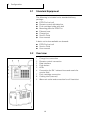
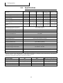
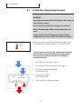
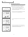
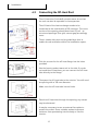
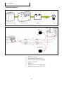
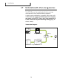
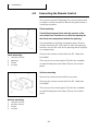
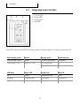
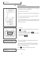
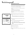
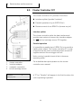
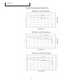
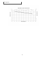
Operation and Installation Manual
EFOY Pro Series
EN
1. Table of Contents
1.
Table of Contents
User Manual
1.
Table of Contents
2.
Introduction
2.1 Foreword
2.2 Safety Information
2.3 Safety notice for methanol
2.4 Normal Operation
2.5 Declaration of Conformity
2.6 Seals of Approval
2.7 Warranty
2.8 Disposal
4
4
5
7
7
8
8
9
11
3.
Configuration
3.1 Standard Equipment
3.2 System Overview
3.3 Specifications
12
12
12
13
4.
Installation
4.1 Installation Space Requirements
4.2 Mounting of the Fuel Cell
4.3 Connecting the Off-Heat Duct
4.4 Connecting the Exhaust Hose
4.5 Installing the Fuel Cartridge Holder
4.6 Electrical Connection to the Battery
4.7 Combination with other energy sources
4.8 Connecting the Remote Control
14
14
16
17
18
20
21
24
25
5.
Operation
5.1 Integrated user interface
5.2 Remote Control
5.3 Select Language
5.4 Remote Control with Computer
5.5 Connecting the Fuel Cartridge
5.6 Automatic Operation
5.7 Switching On manually
5.8 Switching Off manually
5.9 Automatic Antifreeze Feature
5.10 Storage
27
27
28
30
30
31
33
34
34
36
36
2
2
1. Table of Contents
6.
Maintenance
6.1 Service
6.2 Cleaning
38
38
38
7.
Troubleshooting
7.1 Safety
7.2 Problems and Solution
7.3 Problems without Error Messages
7.4 Replacing Service Fluid
39
39
40
42
43
8.
Data Interface and Accessories
8.1 Data Interface Functionality
8.2 Computer Interface Adapter
8.3 GSM Modem GSM-2-SMS
8.4 Fuel Level Sensor FS1
8.5 Cluster Controller CC1
8.6 EFOY ProCube
44
44
44
45
46
46
47
9.
Appendix
9.1 Accessories and Spare Parts
9.2 Output characteristic
48
48
49
3
2. Introduction
Introduction
2.1
Foreword
Thank you for purchasing an EFOY product. We hope that
you will enjoy your new unit.
Please read these instructions first before using and
follow the installation instructions.
Please contact our sales partner where you have bought
the product in case you have questions about installation
or operation.
Manufacturer’s address:
SFC Smart Fuel Cell AG
Eugen-Sänger-Ring 4
D-85649 Brunnthal-Nord
Phone: +49 89 673 5920
Fax: +49 89 673 592 369
Email: [email protected]
web: www.efoy.com
UM-EN-090901 User Manual EFOY Pro | Copyright by SFC Smart Fuel Cell AG 2008. Subject to change without notice
2.
4
2. Introduction
2.2
Safety Information
Read the instructions before operating and keep them
nearby. Be sure to follow all directions in the manual.
Do not open unit or fuel cartridges. Do not use force to
open cartridges and do not refill them. Any
modifications to the unit may affect safe operation, will
lead to a loss of license and will void the warranty Use
only original EFOY equipment.
Do not store unit and fuel cartridges at temperatures
above 45° C. Do not operate at temperatures above
45° C. Keep away from heat and direct sunlight.
Store the unit where there is no danger of freezing, or
use the automatic antifreeze feature. (see Chapter 5.9)
Do not smoke when handling the unit or the fuel
cartridges.
Keep away from heat and open flame.
There is a danger of fire if methanol leaks out (i.e.
following an accident, or if the unit or the fuel cartridge
has been damaged). Keep away from open fire and
make sure area is well ventilated. Small amounts of
methanol which may leak out will evaporate without
leaving any residue.
Keep unit and fuel cartridges (including empty or
partially filled cartridges) out of children’s reach.
Operate the unit only in accordance with instructions
and keep operating area well ventilated. Do not block
exhaust. Avoid inhaling exhaust fumes directly or for
prolonged periods of time.
5
2. Introduction
There is no risk of coming into contact with methanol
provided that you handle the unit and fuel cartridges in
accordance with instructions.
We are required by law to print the following notice.
Methanol is toxic if inhaled, ingested or if it comes into
contact with skin. Irreparable damage may occur if
inhaled, ingested or if it comes into contact with skin. In
the event of an accident or if nausea occurs, consult a
physician immediately. Be sure to bring the fuel
cartridge label or these instructions to the consultation.
(A caution concerning methanol can be found in the
appendix.)
System exhaust may contain harmful components.
Avoid inhaling exhaust directly or for prolonged periods
of time. Use the exhaust hose to conduct exhaust gases
to the exterior.
Improper use or improper connection to other electrical
devices may result in damage.
WARNING
In addition to these safety instructions, please observe
the passages in bold type. Otherwise, you may
endanger yourself and others.
6
2. Introduction
2.3
Safety notice for methanol cartridges
WARNING
You are given the methanol in the form of safe, tested
fuel cartridges that protect you from coming into
direct contact with the contents if used correctly. We
are required by law to print the following notice.
Methanol is easily flammable. Methanol is toxic if
inhaled, ingested or if it comes into contact with skin.
In the event of an accident or if nausea occurs, consult
a physician immediately. Be sure to bring the fuel
cartridge label or the methanol material safety data
sheet to the consultation.
Storage and transport of methanol may be subject to
statutory regulations.
More information is provided in the methanol safety
data sheet on our website www.efoy.com/downloads
or by SFC directly.
2.4
Normal Operation
The EFOY Pro fuel cells are automatic charging devices
for 12V and 24V lead batteries.
The unit may be used only to charge lead batteries that
conform to the specifications in Chapter 3.3.
The unit can be used according the specification in
Chapter 3.3 for stationary and mobile operation in
vehicles. Operate only with original-equipment EFOY fuel
cartridges.
The unit is not intended for emergency medical power
generation, or for powering life-sustaining or agricultural
devices.
The parallel operation of units to increase the charging
current is possible.
7
2. Introduction
The serial operation of units to increase the voltage
output is not permitted.
Do not operate unit if housing is damaged.
2.5
Declaration of Conformity
SFC Smart Fuel Cell AG, Eugen-Saenger-Ring 4, 85649
Brunnthal-Nord declares that the EFOY Pro 600, EFOY
Pro 1200, EFOY Pro 1600, EFOY Pro 1600 LongLife and
the EFOY Pro 2200 conform to the European Community’s
89/336/EWG guidelines for electro-magnetic
compatibility. The following norms apply: DIN EN 610006-1, DIN EN 61000-6-3
2.6
E 24
Seals of Approval
These units have been tested in accordance with ECE
Regulation No. 10 for electro-magnetic compatibility.
Operation in motor vehicles is permitted.
Approval number: E24 10R-020234
These units have undergone voluntary testing by TÜV
SÜD for conformity with the basic requirements of IEC
62282-5 and have been awarded the seal of approval for
product safety.
8
2. Introduction
2.7
Warranty
1. Warranty
Terms of warranty for EFOY Pro 600, 1200, 1600 and
2200
SFC provides a 24-month warranty from the time of
sale for up to 3,000 hours of operation for the EFOY Pro
600, 1200, 1600 und 2200.
Terms of warranty for EFOY Pro 1600 Longlife
FC provides a 30-month warranty from the time of sale
for up to 5,000 hours of operation for the EFOY Pro
1600 Longlife.
The warranty does not extend to improper use of the
unit or operation that is not in accordance with the user
manual, in particular:
If fuel cartridges other than original EFOY fuel
cartridges are used,
Inappropriate handling,
Water damage,
Improper transportation,
If the unit has been opened.
2. Extent of the warranty
The warranty covers defects (see 1. Warranty) from the
time of sale.
The manufacturer shall remedy such defects by either
repair or replacement (updated model where
applicable) as he deems appropriate. Should the
manufacturer provide a warranty, the warranty period
with regard to repair or replacement parts shall not
recommence from the time of service. Instead, the
warranty from time of sale will remain in force. Any
other claims, in particular claims for damages on the
part of the purchaser or a third party, are invalid. The
provisions of the product liability law remain in effect as
well as any claims against the manufacturer pertaining
to warrantees remain in force as provide by law. The
warranty does not extend to any extra costs associated
with mounting or dismounting the unit such as
disassembling furniture or parts of a motor vehicle.
9
2. Introduction
3. In Case of Claim
Always notify the EFOY service center in writing in case
of malfunction. Please describe the defect in detail.
Please also indicate serial number and include the
original invoice. The purchaser must bring or send the
unit to the manufacturer at his own risk so that the
manufacturer can determine whether the defect is
covered by the warranty. The unit must be sent to the
factory as freight. If the defect is covered by the
warranty, the factory shall assume the transportation
costs. Should the defect not be covered by warranty, the
manufacturer shall notify the customer, informing the
customer of what repair costs the manufacturer shall
not assume. The customer shall bear the cost of
transportation in this case.
The manufacturer’s address is:
SFC Smart Fuel Cell AG
Eugen-Saenger-Ring 4
D-85649 Brunnthal
Tel.: +49 89 / 673 59 20
Free Call: 00800 / 73 27 62 78*
Fax.: +49 89 / 673 592 369
[email protected]
www.efoy.com
*The toll-free number is available in the following
countries: Germany, Austria, Belgium, Denmark,
France, Great Britain, Italy, the Netherlands, Norway,
Spain, Sweden and Switzerland.
10
2. Introduction
2.8
Packaging
Disposal
Packaging protects your unit during shipping. All
materials used are environmentally compatible and
recyclable.
We recommend saving the packaging for eventual
winter storage.
Should you nevertheless wish to dispose of the
packaging, please do so properly.
Your dealer or your local recycling center can provide
information about proper disposal.
WARNING
Danger of Suffocation!
Keep packaging away from children. Plastic wrapping
and cartons may cause suffocation.
Fuel Cartridges
Sort empty fuel cartridges with plastics. Dispose of
partly filled fuel cartridges in the same manner as
solvents or paint.
Old Units
Old units are still valuable! Proper disposal can yield
valuable raw materials while protecting the
environment. Your supplier can advise you about
returning old units.
11
3. Configuration
3.
Configuration
3.1
Standard Equipment
The following is included in the standard delivery
package:
EFOY Pro fuel cell
Remote control with data line
Fuel cartridge holder with belt
Mounting plate for EFOY Pro
Exhaust hose
Charge line
Service Fluid
User manual
A basic-set is also available on demand:
EFOY Pro fuel cell
Service Fluid
User manual
3.2
Overview
1
2
3
4
5
6
7
8
9
Charge line connection
Remote-control connection
Data interface
Push button
LEDs
Connection for EH 1 exhaust hose and nozzle for
service fluid
Fuel-cartridge connection
Cooling inlet (reverse)
Warm-air outlet and connection for off-heat duct
12
3. Configuration
3.3
Fuel Cells
Specifications
EFOY Pro 600 EFOY Pro 1200 EFOY Pro 1600
Max. charging power per day
EFOY Pro 1600
EFOY Pro 2200
Longlife
600 Wh/day
1200 Wh/day
1560 Wh/day
1560 Wh/day
2160 Wh/day
Nominal power
25 W
50 W
65 W
65 W
90 W
Nominal voltage
12 V / 24 V
12 V / 24 V
12 V / 24 V
12 V / 24 V
12 V / 24 V
Nominal charging current at 12 V/24 V
2.1 A / 1.05 A
4.2 A / 2.1 A
5.4 A / 2.7 A
5.4 A / 2.7 A
7.5 A / 3.75 A
Recommended
battery capacity*
10 to 100 Ah
5 to 50 Ah
20 to 200 Ah
10 to 100 Ah
25 to 250 Ah
12 to 120 Ah
25 to 250 Ah
12 to 120 Ah
25 to 350 Ah
12 to 175 Ah
7.8 kg
(17.2 lbs)
8.2 kg
(18.1 lbs)
8.4 kg
(18.5 lbs)
8.5 kg
(18.7 lbs)
8,8 kg
(19,4 lbs)
at 12 V
at 24 V
Weight
Switching threshold for automatic
battery charging at 12 V /24 V **
On: <12.3 V / <24.6 V
Off: >14.2V / >28.4 V
Required start-up voltage at 12 V /24 V
>10.5 V / >21.0 V
Noise level (at 1m / 7m distance)
39 / 23 dB(A)
Nominal consumption***
0.9 l/kWh
Quiescent current draw
15 mA
Operating temperature
-20 °C to +45 °C (-4°F to +113°F)
Start-up temperature
+5 °C to +45 °C (41°F to 113°F)
Storing temperature
+1 °C to +45 °C (34°F to 113°F)
Recommended altitude
Up to 1500 m (4920 ft)
Dimensions L x W x D
433 x 188 x 278 mm (17 x 8 x 11 in)
Inclination along the roll axis
Permanent: max. 35°; temporary (<10 min): max. 45°
Inclination along the lateral axis
Permanent: max. 20°
User-Interface
At the unit or via Remote Control with text display
Data-Interface
RJ-45 plug for accessories (e.g. Interface adapter)
Electrical Interface
MNL-plug 4-pins (e.g. Tyco Electronics Universal Mate-N-Lok – Nr. 350779)
* Depends on battery type and application - bigger batteries possible, if charging current sufficient (e.g. solar battery)
** Factory Setting - can be modified with Interface Adapter and PC
*** Effective consumption depends on operating conditions
Fuel Cartridges
M5
M10
M28 (requires M28 adapter)
Volume
5 l (1.32 gallons)
10 l (2.64 gallons)
28 l (7.4 gallons)
Weight
4.3 kg (9.5 lbs)
8.4 kg (18.5 lbs)
22 kg (48.5 lbs)
5.5 kWh
11.1 kWh
31.1 kWh
190 x 145 x 283 mm
230 x 193 x 318 mm
420 x 280 x 360 mm
Nominal capacity
Dimensions L x W x H
13
4. Installation
4.
Installation
4.1
Installation Space Requirements
WARNING
Securely fasten unit and fuel cartridges when using on
board motor vehicles.
Do not operate unit if there is danger of explosion.
Unit is not watertight. Make sure that no water can
enter.
Keep unit and fuel cartridges away from children,
temperatures in excess of 45 °C and direct sunlight.
+45 °C
Make sure when choosing an installation space, that
the temperature ranges between –20 °C and +45 °C.
–20 °C
The unit requires air from the outside and generates
off-heat that needs to be conducted to the outside.
Please take this into account when considering
possible locations.
STACK
HEAT
EXCHANGER
1
Air intake for installation space
2
Air intake for heat exchange and for stack
3
Off-heat from heat exchanger
(see chapter 4.3)
4
Exhaust from stack
(see chapter 4.4)
5
Off-heat from installation space
14
4. Installation
The installation space should have a minimum size of
510 x 350 x 300 mm (L x W x H).
In closed chambers please provide an opening with an
opening cross section of at least 10 cm or 40 cm2 for the
air intake - at structured openings (fine grid, narrow
gap) accordingly more.
Use the off-heat duct to conduct the off-heat out of the
installation space.
The air openings of the installation space need to be
protected against the penetration of water and
particles.
A forced ventilation of the installation space is required
to prevent heat accumulation. This can be done with
additional openings or an additional temperature
controlled ventilator.
Install only in upright position.
Make sure that the device does not exceed the
maximum inclination.
Inclination along the direct axis: 35° (temporary 45°)
Inclination along the quadrature axis: 20° max.
All electrical connections, the fill opening for service
fluid and the fuel cartridge should be easily accessible.
Make sure that the fuel cartridge is located within reach
of the connecting hose (70 cm) and that the hose is
neither kinked nor crushed.
The fuel-cartridge hose and the exhaust hose may not
be damaged. Do not substitute another hose for either
of the two.
Use only original-equipment EFOY hoses.
15
4. Installation
4.2
Mounting of the Fuel Cell
Select a suitable location as described in Chapter 4.1,
paying attention to the dimensions in Chapter 3.3.
1. Secure the mounting plate tightly to the desired
location. Use proper screws and dowels, if
necessary, so that the mounting plate cannot shake
loose in case of an accident.
2. Place the unit onto the mounting plate. It is possible
to mount the unit in 2 possible directions.
3. Put the mounting bar at the screws of the mounting
plate.
4. Move the mounting bar to the fuel cell and then to
the right hand side. Adjust the mounting bar in this
position with the two mounting nuts.
16
4. Installation
4.3
Connecting the Off-Heat Duct
The off-heat duct (included) extracts warm air so that
the unit can also be operated in close quarters.
The off-heat of the heat exchanger needs to be
conducted to the outside with a 100 mm duct. The cross
section of the opening should be at least 35 cm² - at
structured openings (fine grid, narrow gap) accordingly
more.
The air intake side must not be guided by a duct to
enable forced ventilation within the installation space.
Sink the screws for the off-heat flange into the holes
provided.
Use the bow to conduct warm air to the side. If you do
not need the off-heat bow, you can connect the off-heat
tube directly to the flange.
Then pass the off-heat tube to the exterior. You will need
an opening with a 100 mm diameter.
Make sure the off-heat tube has no kinks.
Pass the off-heat tube through the opening; any excess
may be shortened.
It may be necessary to use an external face plate to
protect the outlet. Use a suitable sealant to prevent
moisture from penetrating into the body or into the
interior.
17
4. Installation
4.4
Connecting the Exhaust Hose
Within the fuel cell methanol and oxygen are converted
into water and carbon dioxide. This chemical reaction
generates off-heat which needs to be conducted
together with water vapour and carbon dioxide to the
outside.
WARNING
Connect the included exhaust hose and conduct the
exhaust to the outside.
Exhaust gasses contain moisture and may exceed
60 °C, causing scalding. Exhaust by-products may
contain injurious substances. Avoid inhaling exhaust
directly or for long periods of time.
It is possible to collect the generated water in a
separate water cartridge. But make sure that there is a
hose that allows the gasses including the carbon
dioxide to evaporate from the water cartridge to the
outside.
Remove the cap from the exhaust port. Retain the
cap for winter storage or for possible returns.
Attach the exhaust hose (included) to the exhaust
port.
Route the hose to the exterior and use a suitable
sealant to seal the opening. The hose may be
shortened as needed. The opening must be 10 mm
in diameter.
Make sure the exhaust hose has no kinks or
blockage and that exhaust can escape freely.
18
4. Installation
Routing the exhaust hose
At no time may siphoning occur in the hose. Make sure
that the hose is neither clogged nor blocked.
The exhaust hose may not be longer than 50 cm in
order to prevent freezing in winter. The hose may be
up to 150 cm long for summer operation and during
transitional seasons.
Up
Down
Avoid siphoning
19
4. Installation
4.5
Installing the Fuel Cartridge Holder
WARNING
Keep fuel cartridge and all reserve cartridges away
from children. Keep cartridges away from heat and
out of direct sunshine.
Secure fuel cartridge and all reserve cartridges so
that they can not shift.
Make sure that the fuel-cartridge connecting hose is
neither crushed nor kinked.
Do not place fuel cartridges or reserve cartridges in
front of the air intake or outlet!
COOLING AIR
WARM AIR
Do not place objects such as reserve fuel cartridges in
front of the air intake or outlet.
Place fuel cartridges next to or in front of the unit as
illustrated.
ELECTRICAL CONNECTION
Secure the fuel-cartridge holder with four suitable
screws and dowels, if necessary, so that it will not
shake loose in the case of an accident.
20
4. Installation
4.6
Electrical Connection to the Battery
WARNING
All work should be carried out by qualified technicians
in accordance with technical regulations.
Improper connections or the use of wrong gauge wires
could result in fire.
All wires must be properly insulated and have
adequate voltage rating. All connections must be tight.
The use of uninsulated wires and contacts is not
permitted.
Use the wire harness (included) to connect the unit.
The circuit connecting the battery must contain a fuse.
Check the polarity (see illustration) before connecting
the unit.
Both sensor and power lines must always be
connected.
Always use separate lines for charging (power) and
for voltage metering (sensor) to the battery.
Otherwise, the flow of current will cause false
readings.
The charging lines consists of four leads that must be
connected to the battery as follows:
POWER LEAD
Power lead:
This lead carries current from the fuel cell to the
battery.
Sense lead:
This lead measures battery voltage.
SENSE LEAD
21
4. Installation
To minimize current loss in the leads, the following
cross section is recommended, should the battery
charging cable be insufficient:
Length [m]
<5m
5 – 10 m
10 – 15 m
min. cross section
2,5 mm²
4 mm²
6 mm²
Accessories:
Extension sense line 8 m (Art. No. 151 906 005)
Extension Power line 8 m (Art. No. 151 906 006)
Notes:
The EFOY Pro is charging the connected battery and
the battery supplies the power for the application..
The EFOY Pro can only be used to charge lead
batteries which conform to the technical
specification (see chapter 3.3).
The EFOY Pro can charge 12 V and 24 V batteries
and automatically detects the voltage of the
connected battery.
The charging parameters for the automatic mode
can be adjusted with a standard PC – see user
manual of computer interface adapter.
To protect the battery against deep discharging it is
recommended to install a low-voltage load
disconnector that disconnects the load from the
battery.
22
4. Installation
Connection diagram
EFOY fuel cartridge
EFOY Pro Series
Battery
Load
RED
FUSE 2A
FUSE 15A
1
2
3
4
5
6
7
EFOY Pro Series
connecting line to fuel cell
extension sense line (optional)
battery fuse 2 A
battery
extension power line (optional)
battery fuse in power line 15 A
23
BROWN
4. Installation
4.7
Combination with other energy sources
The EFOY Pro can be combined with other energy
sources which then load the battery together.
A widely used combination is together with solar cells.
In this case it is recommended to adjust the charging
parameter of the EFOY Pro so that it only switches on
if solar alone can not provide enough energy (e.g. in
winter times).
Connection diagram
Solar cell
Charge controller
Battery
Load
EFOY fuel cartridge EFOY Pro Series
24
4. Installation
4.8
Connecting the Remote Control
The remote control (1) displays the current status and
is used to control the device. Mount the panel where it
is easily accessible.
1
Flush mounting
2
If installing the panel flush with the surface of the
unit, make sure that there is a sufficient opening for
the electronic components behind the opening.
3
4
Connect the remote control with the DL 1 data line
(included).
Flush mounting:
1 remote control
2 opening
3 frame
4 screws
1
Use templates for drilling and sawing when flush or
surface mounting (2). Use a drill to start the opening
and then cut out the rest of the opening with a keyhole
or compass saw.
Then secure the control panel (1) with four suitable
screws (4) and place the frame (3) over the control
panel.
Surface mounting
2
Secure the surface mount with two screws.
Connect the remote control with the DL 1 data line
(included).
3
4
Then secure the control panel (1) with four suitable
screws (4) and place the frame (3) over the control
panel.
Surface mounting:
1 remote control
2 surface mount
3 frame
4 screws
25
4. Installation
Connect the remote control with the DL data line
(included).
Then insert the plug into the left socket on the unit
marked “Remote Control“.
If the DL 1 data line is not long enough, you can replace
it with a commercially available network line that is
longer or shorter (Category 5 patch cable).
26
5. Operation
5.
Operation
5.1
Integrated user interface
1
2
3
4
Push-button
Green LED
Yellow LED
Red LED
The LED’s indicate the EFOY Pro system status. The push-button is used to control the unit.
Push-button action
Result
Starting state
Resulting state
Push shortly (< 0,5s)
Reset
On, Off or Automatic
Automatic
Push longer (> 3s)
Switch On / off
On or Automatic
Off
Off
On
LED state
Green LED
Yellow LED
Red LED
On
Ready
Add service fluid
Error
Blinking
Shutting down
Fuel empty
Interruption
Off
Off or error
No error
No error
27
5. Operation
5.2
Remote Control
The optional remote control displays the current status
and is used to control the EFOY Pro.
Remote control connection:
Connect the remote control with the included data line
DL1.
Then insert the plug into the left socket on the EFOY
Pro marked „Remote Control“.
If the included data line DL1 is not long enough, you can
replace it with a commercially available network cable
(Cat. 5 patch cable).
auto
reset
!
Automatic
Please change fuel cartridge
1 Display
2 Information button and language-selection button
>>
3 On/Off button
4 Button for automatic operation auto
5 Yellow warning light “Please change fuel cartridge“
6 Red error warning light
7 Reset button reset
The first line indicates the operating mode selected,
such as “Automatic“.
The second line of the display provides information
about normal operation, errors or malfunctions (see
Chapter 7 Troubleshooting).
Press >> to obtain the following information.
Automatic
Voltage 13.6 V
Battery voltage
28
5. Operation
Automatic
Current 4.6 A
Automatic
V03 9.06I12V/24V QB
Charging current
Please note that the device interrupts power
generation briefly several times an hour during
normal operation and a charging power of 0.0 A is
displayed then.
Firmware version
Please check on a regular basis (at least once a
year), if software updates are available.
Automatic
100200-0808-0002
Automatic
Operating hours 500 h
Automatic
Standby
Automatic
Charging mode
Serial number
Total operating hours
Standard display
The standard display will be restored after about 30
seconds. Alternatively, you can return to the
standard display by pressing >> again.
If you have connected the optional cartridge sensor
to your unit, a fuel cartridge will appear in the
display as soon as a predetermined amount is
reached.
Always keep a reserve fuel cartridge at the ready.
The cartridge need only be changed when the
message “Please change cartridge“ appears in the
display.
29
5. Operation
5.3
Select Language
Press >> on the control panel for two seconds. The
control panel will display the language currently
selected.
The following languages are available:
German (factory setting)
English
French
Italian
Dutch
Spanish
Deutsch
Continue pressing >> until the desired language
appears.
Then hold >> 2 more seconds in order to set your
language choice.
5.4
Remote Control with Computer
It is also possible to remote control the EFOY Pro with a
computer. By using a modem this can also be done
remotely. The computer interface enables the same
functions as the remote control (see chapter 8).
30
5. Operation
5.5
Connecting the Fuel Cartridge
WARNING
For safety’s sake, use only original EFOY fuel
cartridges. Do not smoke while changing the cartridge
and avoid open flames! Do not expose fuel cartridges
to temperatures above 45 °C.
Do not place the fuel cartridge in front of the air intake
or outlet.
Original-equipment EFOY fuel cartridges contain
EFOY-approved methanol. Even slight impurities in
commercially available methanol may cause
permanent damage to the unit and may void the
warranty.
Please pay attention to the Safety notice for methanol
cartridges (chapter 2.3)
Note: When the cartridge is empty, “Please change
fuel cartridge“ will appear on the remote control and
the yellow light at the EFOY Pro and the remote
control will blink. The cartridge may be changed while
the system is running.
Unscrew the empty fuel cartridge and remove.
Close each cartridge tightly with the cap after use.
EFOY fuel cartridges are intended for one-way use
only. They may not be refilled.
Sort empty fuel cartridges with plastics. Dispose of
partly filled fuel cartridges in the same manner as
solvents or paint.
31
5. Operation
1
Place a new sealed original-equipment EFOY fuel
cartridge in the system (1).
Make sure the cartridge is fixed properly for
mobile applications (2).
Only remove the childproof cap when the new fuel
cartridge has been placed into the fuel-cartridge
holder (3).
Screw the connector onto the new fuel cartridge.
Press reset on the control panel to extinguish the
yellow warning light and the maintenance message.
2
Notes:
For mobile applications the fuel cartridge needs to
be properly fixed with a fuel cartridge holder.
The optional M28 adaptor is required to connect the
M28 cartridge to the EFOY Pro.
3
Connect the M28 fuel cartridge
Connect the EFOY Pro fuel cartridge connector (1)
with the M28 adaptor (2).
Screw the M28 adaptor (2) onto the M28 fuel
cartridge (3).
32
5. Operation
5.6
Automatic Operation
CAUTION
Before connecting to the electrical system, make sure
the unit has been positioned properly and that the
electrical system is protected by fuses (as described
in Chapter 4.6).
As soon as you connect the unit to the battery and after
every reset the unit will start the automatic operation
mode.
The unit monitors the battery voltage and starts
charging as soon as the battery voltage drops bellow a
defined threshold. It will stop charging as soon as the
battery voltage exceeds the defined switch off
threshold.
The thresholds for automatic charging can be modified
with a computer – see Computer interface user manual.
Please note that the device interrupts power
generation briefly several times an hour during
normal operation and a charging power of 0.0 A is
displayed then.
Automatic
Charging mode
Automatic
Start phase
Automatic
Standby
Automatic
Please change fuel cartridge
The second line of the display will indicate “charging
mode“ as long as the unit is providing voltage to the
electrical system.
The device goes through a cold start phase of about 20
minutes before reaching its full rated output.
If the battery is sufficiently charged and the unit is not
providing input, the unit will remain in the standby
mode.
Should the device detect a malfunction such as an
empty fuel cartridge, it will shut down and advise you
how to correct the situation. (“Please change fuel
cartridge“.) Resume automatic operation using the
reset button after the error has been corrected
(See Chapter 7).
33
5. Operation
5.7
Switching On manually
If desired, you can switch on the unit manually regardless of the battery voltage. The unit will then be in the
“charging mode“.
This function is only possible when the battery voltage
is below 13.2V / 26.4 V.
Press
on the control panel once if the unit has been
switched off, and twice if it is operating in automatic
mode. The unit will start up regardless of the battery
voltage and will continue charging until it reaches the
switch-off point.
On
Charging mode
The device will then switch to automatic mode by itself
and will only charge if the battery or the demand for
power requires it.
5.8
Switching Off manually
Press
on the remote control to switch off the device.
The unit will gradually shut down, performing various
function checks as it does so:
Off
Shutting down
To protect components, the unit must run at least
30 minutes before shutting down. If the unit is shut off
beforehand, it will continue running until 30 minutes
have elapsed. The message “Shutting down” will
appear in the display. Leave the fuel cartridge and the
battery connected during this time.
Please note that the fuel cell will not charge the
battery automatically if it is switched off. The unit
needs to be switched on manually and can only start
up if it is connected to an intact battery and full fuel
cartridge.
34
5. Operation
5.9
Off
Antifreeze mode
Automatic Antifreeze Feature
This unit features an intelligent antifreeze feature. If the
temperature drops close to the freezing point then the
EFOY Pro starts automatically the charging mode to
prevent freezing. As soon as the unit has warmed up
enough it stops the antifreeze mode. The antifreeze
mode works also if the unit is switched off.
If the unit is in antifreeze mode, the message
“Antifreeze mode” will appear on the second line. The
first line will indicate the current operating mode, for
example “Off”.
The antifreeze function works only as long as a fuel
cartridge and a sufficiently intact battery are
connected.
Please observe the following maintenance tips for
storage and winter operation:
If, despite precautions, the unit does freeze, let it thaw
in a warm place for approximately 24 hours before
operating. Please note that the unit’s performance may
diminish if it freezes repeatedly.
Running in straight antifreeze mode, the unit will
consume approximately 10 liters of methanol in the
course of a five-month Central European winter.
35
5. Operation
5.10 Storage
Press
Off
Antifreeze mode
on the remote control to switch off the unit.
Wait until the unit has shut down and the display has
disappeared (approx. 30 min.).
Unplug the charging line and the data line for the
remote control.
Store the plugs and lines in a cool, dry place.
WARNING
Do not smoke when handling unit and fuel
cartridge. Keep away from open flame!
CAUTION
Unscrew the fuel cartridge and close it with a cap.
Keep all elements clean.
WARNING
Keep unit and fuel cartridges – even empty or
partially empty cartridges – away from children.
Remove the exhaust hose. Keep it clean and place a
cap over the exhaust outlet.
Remove the off-heat tube and the off-heat bow if
necessary and remove the EFOY Pro from the
mounting plate. .
CAUTION
Store unit in a cool place; however, the temperature
should exceed 1° C because the automatic
antifreeze feature will only work if a fuel cartridge
is attached along with a sufficiently charged battery.
(See Chapter 5.9)
CAUTION
If the device is exposed to temperatures below
0 °C without connected batteries and sufficiently
filled fuel cartridges (frost protection), it must be
thawed out for approximately 24 hours at room
temperature before commencing operation.
36
5. Operation
Use a proper box such as the original carton to ship
the unit. Use padding to prevent shocks. Transport
the unit in an upright position only.
37
6. Maintenance
6.
Maintenance
6.1
Service
WARNING
Do not open unit! Unauthorized tampering may
jeopardize safe operation and void any warranty. The
unit does not contain any components that you can
service or repair yourself.
The unit is maintenance free under normal operating
conditions.
Please check on a regular basis (at least once a year),
if software updates are available.
6.2
Cleaning
WARNING
Switch off device before cleaning and unplug the
battery charging cable.
CAUTION
The device is not watertight. Make sure that moisture
cannot get inside.
Clean only with a soft cloth dampened with a mild
detergent.
Reconnect the battery charging cable after cleaning so
that the antifreeze feature remains activated. (See
Chapter 5.9).
38
7. Troubleshooting
7.
Troubleshooting
7.1
Safety
WARNING
Do not open unit! It contains no components that you
can repair yourself.
Please contact our sales partner where you have
bought the product if you are unable to fix a
malfunction by using these instructions.
Manufacturer’s address:
SFC Smart Fuel Cell AG
Eugen-Sänger-Ring 4
D-85649 Brunnthal-Nord
Phone: +49 89 673 5920
Fax: +49 89 673 592 369
Email: [email protected]
Web: www.efoy.com
39
7. Troubleshooting
7.2
Problems and Solution
At the EFOY Pro and at the remote control the red and
yellow light indicate a system error. The remote control
additionally shows a detailed error message..
The messages will assist you in solving the problem
quickly and easily.
Press the reset button on the control panel AFTER the
problem has been solved.
Message
Solution
Check connection
Check remote control connection – proper socket on
the EFOY Pro is marked „Remote Control“.
or
Check battery
Check battery voltage. If under 10.5 V, use an external
battery charger to recharge.
Interruption: Please defrost
device slowly
The unit is frozen. Let stand at room temperature for
approx. 24 hours before operating.
(Error 40)
Interruption: Surroundings too
warm
Ambient temperature is too high. The unit starts again
as soon as it has cooled down.
(Error 32, 41)
Please contact service
(Error 1, 10, 13, 14, 15, 17,
70, 73, 75, 76, 80, 83, 84)
System periphery error. Please contact the SFC partner
where you have bought the product if the problem
remains after a restart.
Please check exhaust hose
Stack does not reach expected voltage.
(Error 11, 12, 18)
Check that the exhaust hose has been properly
connected and arrange it so that condensation cannot
form.
Check for kinks. Clean hose if necessary and keep
opening clear.
Please change fuel cartridge
Insert a new fuel cartridge as described in Chapter 5.5.
(Error 20, 21, 22, 23)
Check connection and screw cartridge on tightly.
Check cartridge hose for kinks. Check hose and
connection for dirt.
40
7. Troubleshooting
Message
Solution
Please check fuel cartridge
connector
Check fuel cartridge connection and screw cartridge on
tightly.
(Error 72)
Check cartridge hose for kinks. Check hose and
connection for dirt.
Please refill service fluid
Add service fluid (see Chapter 7.4).
(Error 30, 31)
Check that exhaust can escape and that ambient
temperature is below 45° C.
Please check battery voltage
Error 50: Battery voltage is too low (sense line)
(Error 50, 51, 52, 53)
Error 51: Battery voltage is too high (sense line)
Error 52: Battery voltage is too low (power line)
Error 53: Battery voltage is too high (power line)
Check connections.
Check whether the battery is the proper type.
Check battery voltage. If too low, use an external
battery charger to recharge.
Check other charging devices such as generators or
regulators for defects.
Automatic restart
Unit is restarting automatically - please wait.
(Error 63, 65)
41
7. Troubleshooting
7.3
Problems without Error Messages
Please check the following if the device doesn’t respond
and nothing is displayed on the remote control.
If problem recurs: please contact the SFC partner
where you have bought the product.
Cause
Solution
Remote control has no or
wrong connection
Check remote control connection
No battery connected, wrong
battery or undercharged.
Check contacts, polarity, cables and battery fuses.
Short-circuit fuse tripped
Check polarity of charge line.
Connect a charged battery to start device.
Turn off unit, check reason for short circuit/overload or
wrong polarity and correct
If problem recurs
Contact the hotline at:
Freecall: 00800 732 762 78
Hotline: +49 89 673 5920
[email protected]
www.efoy.com
42
7. Troubleshooting
7.4
Replacing Service Fluid
If service fluid is low the yellow light will turn on at the
EFOY Pro and the message ”Please refill service fluid“
will appear at the control panel display.
There is no need to add service fluid prior to the initial
start-up.
Use EFOY brand service fluid only.
Switch off the unit before refilling fluid. Unplug the
charge line.
Always keep the device’s service fluid nozzle clean.
Use a clean pair of scissors to cut off the tip of the
cap.
The service fluid bottle is for one time use only.
Remove the exhaust hose from the device’s service
fluid nozzle.
Insert the tip into nozzle and gently squeeze the
entire contents into the nozzle.
Never refill more than one bottle of Service Fluid at
a time.
Wipe off any spilled service fluid with a cloth.
Replace the exhaust hose.
Reconnect the charge line.
Order a spare bottle service fluid at your local
dealer.
43
8. Data Interface and Accessories
8.
Data Interface and Accessories
8.1
Data Interface Functionality
The EFOY Pro data interface enables the connection of:
Computer or Modem with the interface adapter IA1
Fuel cartridge sensor FS1
Cluster Controller CC1
DuoCartSwitch
2
3
1
Important: the data interface cannot be connected
directly to a computer - the interface adapter is
required for this.
On/Off
Reset
Pin configuration of data interface:
Pin 1: Output (reserved)
Pin 2: RS232 RxD (Receive)
Pin 3: RS232 TxD (Transmit)
Pin 4: Ground
Pin 5: + Battery voltage
Pin 6: Input fuel cartridge sensor (FS1)
Pin 7: Input Remote-on contact (CC1)
Pin 8: Master/slave parallel operation control (CC1)
Remote
Data
Control Interface
Power
Sense
1
2
3
data line
interface adapter
PC (COM interface)
8.2
Computer Interface Adapter
With a computer it is possible to communicate with the
EFOY Pro via a serial COM interface. By using a modem
this can also be done remotely.
This enables to check the current system status,
change parameter or remote control the EFOY Pro.
For a detailed description please see the computer
interface adapter user manual.
The Interface Adapter IA1 is used to connect the EFOY
Pro to a computer COM-interface.
The USB-Adapter is used to connect the interface
adapter to a computer USB-interface, if no COMinterface is available.
44
8. Data Interface and Accessories
8.3
GSM Modem GSM-2-SMS
The optional GSM modem allows to control and
configure the EFOY Pro remotely. It is recommended to
use such a solution if the EFOY Pro is installed
remotely.
Functions:
Notification if errors occur
Notification if fuel cartridge goes low (with optional
fuel cartridge sensor FS1)
Remote diagnostics
Remote control
Remote programming
For further details see GSM modem user manual,
8.4
Fuel Level Sensor FS1
The EFOY Pro by default does not supervise the fuel
cartridge level. The EFOY Pro will go in an error as
soon as the fuel cartridge is empty.
The optional fuel cartridge sensor FS1 monitors the
level of the fuel cartridge and indicates if the fuel level
drops below the position where the fuel cartridge
sensor is positioned at the fuel cartridge. This early
warning gives the user time to change the cartridge
before it is completely empty and the fuel cell stops.
This sensor should be combined with a remote
management system – e.g. the GSM modem GSM-2SMS.
The FS1 is mounted with two screws at the fuel
cartridge holder. There are two different levels
available to mount the FS1.
The FS1 sensor is connected to the EFOY Pro data
interface.
45
8. Data Interface and Accessories
8.5
Cluster Controller CC1
The cluster controller CC1 provides 3 functions:
Interface splitter (provide 2 sockets)
Parallel operation of up to 5 EFOY Pro’s
Remote control of one EFOY Pro (remote-on pin)
Interface splitter
The cluster controller splits the data interface and
provides two sockets to connect the interface adapter
IA1 and the fuel cartridge sensor FS1 together.
Parallel operation
It is possible to parallel up to 5 EFOY Pro’s to provide a
higher power output. The cluster controller C1 is used
to synchronize the units so that they switch on and off
together and act like one bigger fuel cell.
Units running in parallel must all be in the same
operating mode.
1
2
3
4
cluster controller
interface adapter
computer connection
to fuel cartridge sensor
Automatic
Charging mode
P
For a detailed description please see the cluster
controller user manual.
A “P” for “Parallel” will appear in the first line when the
unit is operating in parallel.
46
8. Data Interface and Accessories
Remote control (remote-on)
The EFOY Pro can be activated via a switching contact at
the CC1, which means that the charging mode can be
activated
The same function can be activated via the computer
interface. .
Automatic
Charging mode
R
Automatic
Charging mode
R
An “R” for “remote” will appear in the first line when
the unit is operating in remote mode.
You can lock or unlock the unit’s software from a
remote location by pressing auto and >>
simultaneously. This will deactivate the function and the
unit cannot be started by a remote signal.
If you have locked the software, a padlock
in the first line of the display.
8.6
will appear
EFOY ProCube
The EFOY ProCube is a modular plug&play solution for
outdoor operation of the EFOY Pro.. The unit includes
preinstalled electronics, air ventilation and all
mounting materials. The integrated solar charge
controller allows the easy combination with solar
panels. .
The EFOY ProCube allows the installation of:
1x EFOY Pro (600, 1200, 1600)
1x Fuel cartridge (M5, M10 or M28)
1x Battery (40, 60, or 90 Ah)
1x Fuel cartridge sensor FS1
1x GSM modem GSM-2
47
9. Appendix
9.
Appendix
9.1
Accessories and Spare Parts
WARNING
Use only original equipment! Use of unauthorized
parts compromise safety and void the warranty.
For a full accessories and spare parts list please visit
www.efoy.com
48
10. Appendix
10.
Appendix
U-I and U-P characteristic as per CE test
49
10. Appendix
EFOY 2200: U-I and U-P Characteristic
Output Current [A]
Output Voltage [V]
50
Output Power [W]
Output Current [A]
Output Power [M]
0. Appendix
Appendix
51
www.efoy.com
©EFOY is a registered trademark of SFC Smart Fuel Cell AG