1
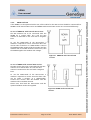
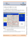
User manual ADMA Version 2x.6.1.4 Hardware V. 2.x / Firmware v.2x.6.0 and higher X Z Y GeneSys Elektronik GmbH Offenburg Date: March 2009 Document revision 2x.6.1.4 Date: March 2009 ADMA User manual Note GENESYS ELEKTRONIK strives to maximize the accuracy of all its data and specifications, but cannot rule out the possibility of errors and reserves the right to future modifications without any prior notice. GENESYS ELEKTRONIK is not obliged to maintain secrecy over any received material or other information in the absence of any corresponding agreements made with GENESYS prior to submission of such information. GENESYS will gladly respond to enquiries and provide product details. Copyright Copyright @ 2006 GENESYS ELEKTRONIK GmbH. All rights reserved. This entire user manual, or excerpts thereof, must not be reproduced, stored or transmitted in any manner – electronically, mechanically or otherwise – without the prior approval of GENESYS ELEKTRONIK GmbH. Windows is a registered trademark of Microsoft Corporation. DIAdem is a registered trademark of National Instruments. Revision Document revision 2x.6.1.4 Date: March 2009 Contact GeneSys Elektronik GmbH In der Spöck 10 D-77656 Offenburg Phone: 0049-781-969279-30 Fax: 0049-781-969279-11 www.genesys-offenburg.de Document revision 2x.6.1.4 Page 2 of 52 Date: March 2009 ADMA User manual Table of contents Introduction............................................................................................................................5 1. 2. Scope of delivery ....................................................................................................................5 2.1. ADMA only ............................................................................................................................ 5 2.2. ADMA with internal / external GPS receiver ........................................................................... 6 2.3. ADMA with a GPS receiver and GPS base station ................................................................... 7 3. ADMA laboratory bench testing ............................................................................................9 3.1. General information............................................................................................................... 9 3.2. Setup and cabling.................................................................................................................. 9 3.3. Modifying the ADMA's configuration................................................................................... 10 3.3.1. Handling of the ADMA System Software (Help)............................................................... 10 3.3.2. Loading configuration from the ADMA ........................................................................... 11 3.3.3. Configuring measurement data transmission via the COM interface ............................... 12 3.3.4. Selection of data packets to be transmitted .................................................................... 13 3.3.5. Auxiliary systems.............................................................................................................. 14 3.3.6. Parameter ........................................................................................................................ 15 3.3.7. Transmitting modified settings to ADMA ........................................................................ 16 3.4. Starting a measurement....................................................................................................... 17 3.4.1. Data recording – principle of operation ........................................................................... 20 3.4.2. Standard recording.......................................................................................................... 21 3.4.3. Sequential recording........................................................................................................ 21 3.5. Static test............................................................................................................................. 22 3.5.1. Transient condition of the Kalman filter .......................................................................... 22 3.5.2. Checking the system status.............................................................................................. 22 3.5.3. Checking displayed orientation........................................................................................ 23 3.5.4. Checking displayed rotational speeds .............................................................................. 24 3.5.5. Checking the displayed accelerations............................................................................... 25 3.5.6. Stopping a measurement ................................................................................................ 25 3.6. Dynamic test ........................................................................................................................ 26 3.6.1. Test procedure and data display ...................................................................................... 26 3.6.2. Checking the rotational speeds........................................................................................ 26 3.6.3. Checking accelerations .................................................................................................... 27 4. Installation and cabling inside the vehicle...........................................................................28 4.1. Operational configurations .................................................................................................. 28 4.2. Point of installation.............................................................................................................. 29 4.2.1. ADMA .............................................................................................................................. 29 4.2.2. External speed measuring system .................................................................................... 29 4.2.3. GPS antenna .................................................................................................................... 29 4.2.4. Modem and modem antenna .......................................................................................... 29 4.3. Cabling ................................................................................................................................ 30 4.3.1. ADMA in stand-alone mode (minimal configuration) ...................................................... 30 4.3.2. ADMA in stand-alone mode - optional connections ........................................................ 30 4.3.3. ADMA and external speed measurement......................................................................... 30 4.3.4. ADMA and GPS................................................................................................................ 31 4.3.5. ADMA and DGPS with a separate base station ................................................................ 32 5. Setting up the ADMA in the vehicle.....................................................................................33 5.1. Configuration of the external velocity.................................................................................. 33 5.2. Satellite based GPS correction data...................................................................................... 34 5.3. Modify threshold for AutoInit function and GPS-course ...................................................... 35 5.4. Modify threshold for standstill detection ............................................................................. 36 5.4.1. Max. turn rate at standstill............................................................................................... 37 5.4.2. Max. velocity at standstill ................................................................................................ 37 5.5. Modify thresholds for quality............................................................................................... 38 Document revision 2x.6.1.4 Page 3 of 52 Date: March 2009 ADMA User manual 5.5.1. Threshold for position quality.......................................................................................... 39 5.5.2. Threshold for Tilt quality.................................................................................................. 39 5.5.3. Enter geo. latitude and geo. longitude ............................................................................ 39 5.6. Compensating an ADMA misalignment ............................................................................... 40 5.6.1. ADMA misalignment........................................................................................................ 40 5.6.2. Sequence of ADMA misalignment angle compensation .................................................. 40 5.6.3. Horizontal compensation of a ADMA misalignment ........................................................ 40 5.6.4. Compensation of ADMA's vertical axis misalignment....................................................... 41 5.6.5. Compensation of vertical-axis misalignment of a 2-axis speed sensor ............................. 41 5.7. Compensating the installation position ............................................................................... 42 5.7.1. Virtual measuring point (point of interest) ...................................................................... 44 5.7.2. External speed measuring system .................................................................................... 44 5.7.3. GPS antenna .................................................................................................................... 44 6. Configuring ADMA's measurement mode ...........................................................................45 6.1. System settings.................................................................................................................... 45 6.2. Starting a measurement ...................................................................................................... 45 6.2.1. Start measurement in the ADMA System Software.......................................................... 45 6.2.2. Remote Start in the ADMA System Software ................................................................... 45 6.2.3. Autostart mode ............................................................................................................... 46 6.2.4. Start a measurement via a user specific tool.................................................................... 46 6.2.5. Start course ..................................................................................................................... 46 6.2.6. AutoInit function (yaw angle init).................................................................................... 46 6.2.7. Pre-alignment .................................................................................................................. 47 6.2.8. Transient phase of the Kalman filter ................................................................................ 47 7. ABD Steering Robot (HW 2.2 and higher)............................................................................48 7.1. ADMA-configuration for ABD-steering robot ....................................................................... 48 7.2. Measurement....................................................................................................................... 49 8. ADMA – firmware download................................................................................................50 8.1. General ................................................................................................................................ 50 8.2. Firmware / System Software – Compatibility........................................................................ 50 8.3. Handling Ini-files created by older System Software versions............................................... 50 8.4. Download ADMA firmware.................................................................................................. 51 Document revision 2x.6.1.4 Page 4 of 52 Date: March 2009 ADMA User manual 1. Introduction This user manual serves as an aid in commissioning the ADMA gyro system. The first part of the manual describes a routine for testing whether the ADMA gyro system's inertial sensors are operating without error. This function test is also a good way to become familiar with ADMA and to gain experience in setting up the ADMA. The second part of the manual describes a typical configuration of a test vehicle, including auxiliary sensors such as an external speed measurement system or a GPS. 2. Scope of delivery 2.1. • • • • • • • • ADMA only The ADMA module A supply cable designated ADMA-Power, colour code red A communication cable designated ADMA-COM, colour code blue A communication cable designated ADMA-CAN, colour code green ADMA Download – cable, colour code white The configuration tool designated ADMA System Software Documentation (User manual, Technical Documentation and ADMA System Software) Transport case Optional items: HW 2.2 and higher versions • Signal-In-cable, colour code orange • Signal-Out-cable, colour code yellow • ADMA-Speed-cable, colour code grey • Rescue case with replacement cable and download-software HW 2.1 • Event-In 1 - cable, colour code orange • Event-In 2 - cable, colour code orange • Sync Out - cable, colour code yellow • Error Out – cable, colour code black • Aux-Out – cable, colour code black • ADMA Speed – cable, colour code grey • Rescue case with replacement cable and download-software Document revision 2x.6.1.4 Page 5 of 52 Date: March 2009 ADMA User manual 2.2. • • • • • • • • • • • • • • • ADMA with internal / external GPS receiver The ADMA or ADMA-G module A supply cable designated ADMA-DC In, colour code red A communication cable designated ADMA-COM, colour code blue A communication cable designated ADMA-CAN, colour code green A ADMA Download – cable designated Prog, colour code white with programming adapter The configuration tool designated ADMA System Software Documentation (User manual, Technical Documentation and ADMA System Software) Transport case for ADMA or ADMA-G GPS receiver (only by ADMA with external GPS-Receiver) GPS supply cable (only by ADMA with external GPS-Receiver) GPS communication cable (only by ADMA with external GPS-Receiver), colour code brown GPS rover antenna with cable (in case ADMA-G with, in case ADMA without, colour code brown) Magnetic base for GPS rover antenna Documentation (GPS receiver) Transport case for GPS-Rover Optional items: HW 2.2 and higher versions • Signal-In-cable, colour code orange • Signal-Out-cable, colour code yellow • ADMA-Speed-cable, colour code grey • Radio modem or GSM modem • Radio/ GSM modem antenna with magnetic base and antenna cable • ADMA-G modem connection cable, colour code brown (only with ADMA-G with internal GPS) • GPS modem connection cable (only with ADMA with external GPS Receiver) • Receiver enabling for WAAS • Rescue case with replacement cable and download-software HW 2.1 • Event-In 1 - cable, colour code orange • Event-In 2 - cable, colour code orange • Sync Out - cable, colour code yellow • Error Out – cable, colour code black • Aux-Out – cable, colour code black • ADMA Speed – cable, colour code grey • Radio / GSM modem • Radio / GSM modem antenna with magnetic base and antenna cable • ADMA-G modem connection cable, colour code brown (only with ADMA-G with internal GPS) • GPS modem connection cable (only with ADMA with external GPS) • Receiver enabling for WAAS • Rescue case with replacement cable and download-software Document revision 2x.6.1.4 Page 6 of 52 Date: March 2009 ADMA User manual 2.3. ADMA with a GPS receiver and GPS base station In the base station the GPS receiver, wireless / GSM modem and associated cables are integrated into a housing. The antenna, communication and supply cables need simply to be plugged into the external connectors provided for this purpose. • • • • • • • • • • • • • • • • • • • • • • • • • • • The ADMA or ADMA-G module A supply cable designated ADMA-DC In, colour code red A communication cable designated ADMA-COM, colour code blue A communication cable designated ADMA-CAN, colour code green The configuration tool designated ADMA System Software ADMA Download – cable designated ProgSys I, colour code white with programming adapter Documentation (User manual, Technical Documentation and ADMA System Software) Transport case for ADMA or ADMA-G GPS receiver (only with ADMA with external GPS-Receiver) GPS supply cable (only with ADMA with external GPS-Receiver) GPS communication cable (only with ADMA with external GPS-Receiver), colour code brown GPS rover antenna with cable (in case ADMA-G with, in case ADMA without, colour code brown) Magnetic base for GPS rover antenna with assembly adapter Documentation (GPS receiver) Transport case for GPS-Rover GPS base receiver integrated into a housing GPS base supply cable GPS base communication cable GPS base antenna and cable Wireless / GSM modem integrated into a housing Wireless / GSM modem antenna and antenna cable Connection cable from GPS base to Wireless/GSM modem Wireless/GSM modem power supply unit 220V Tripods for GPS base antenna and Wireless/GSM modem antenna Mounting structure for GPS base antenna and Wireless/GSM modem antenna Documentation (on the GPS receiver and GPS control terminal) Transport case for GPS base Document revision 2x.6.1.4 Page 7 of 52 Date: March 2009 ADMA User manual Optional items: HW 2.2 and higher versions • Event-In 1 cable, colour code orange • Event-In 2 cable, colour code yellow • ADMA Speed – cable, colour code grey • Radio / GSM modem • Radio / GSM modem • ADMA-G modem connection cable, colour code brown ( only with ADMA with internal GPS) • GPS modem connection cable (only with ADMA with external GPS) • Long-wave receiver for DGPS correction data • Power regeneration box 7…34 V • Rescue case with replacement cable and download software HW 2.1 • Event-In 1 - cable, colour code orange • Event-In 2 - cable, colour code orange • Sync Out - cable, colour code yellow • Error Out – cable, colour code black • Aux-Out – cable, colour code black • ADMA Speed – cable, colour code grey • Wireless / GSM modem • Wireless / GSM modem antenna with magnetic base and antenna cable • ADMA-G modem connection cable, colour code brown (only with ADMA-G with internal GPS) • GPS modem connection cable (only with ADMA with external GPS) • Power regeneration box 7 .. 34 Volt • Rescue case with replacement cable and download-software Document revision 2x.6.1.4 Page 8 of 52 Date: March 2009 ADMA User manual 3. ADMA laboratory bench testing 3.1. General information The routine described below is intended to test the functionality of the gyro system's inertial sensors, i.e. the accelerometers and gyroscopes. This function test is also a good way to become familiar with the ADMA and to gain experience in setting up the ADMA. 3.2. Setup and cabling The following components should be prepared for the function test: • ADMA • ADMA-Power supply cable • ADMA-COM communication cable • A PC / laptop with the ADMA System Software Connect the ADMA-Power cable's red-coded Lemo-plug to the DC In ADMA socket and turn on the power supply. Depending on system design, the nominal supply is 12, 24 or 42 VDC. The DC In LED should come on as a result. Afterward, connect the ADMA-COM communication cable's blue-coded Lemo-plug to the COM ADMAsocket and the other end of the cable to the COM interface of your measurement data acquisition device (usually a PC or laptop). These connections are also depicted in the diagram below. Figure 1 Setup an cabling Document revision 2x.6.1.4 Page 9 of 52 Date: March 2009 ADMA User manual 3.3. Modifying the ADMA's configuration 3.3.1. Handling of the ADMA System Software (Help) For a better usability of the ADMA System Software, an interactive help has been implemented. With each parameter available in the configuration mode a hint will be displayed, and, if applicable, an image, to assure that the most important information are available for the user. To have the parameter hint displayed, set the focus to the appropriate control element. In case of pure keyboard editing, you can tab (shift+tab) through the control elements. In case of option control elements simply use the arrow keys. If you prefer working with a mouse or touchpad, the focus can be set with a right button click. This only displays the hint of an option control element or a checkbox, thus having focus, but not changing its state. To activate or deactivate these control elements please use the left mouse button. If the displayed information isn’t sufficient, you can obtain further information by clicking on the Helpbutton on the very bottom of the window to open the Technical documentation. Please note, that a PDF-reader has to be installed. To make fast and efficient working with ADMA System Software possible, the most important functions are available via Hotkeys. An overview listing all preset hotkeys is given at the main menu’s item Hotkeys. Please note, that the Hotkeys are not available all the time. Document revision 2x.6.1.4 Page 10 of 52 Date: March 2009 ADMA User manual 3.3.2. Loading configuration from the ADMA Certain settings need to be enabled in order to conduct the function test. For this purpose, it is necessary to check and possibly modify the configuration saved in the ADMA system. To view and change these configuration parameters, start the ADMA System Software and select the menu option Configuration. Figure 2 Menu of the ADMA System Software The following dialog will open, where you can choose the source to load the configuration data from. For function testing the settings should be loaded from the ADMA. Please choose the option Load settings from ADMA and confirm with the button Load / Generate settings. Figure 3 Dialog: Load configuration The ADMA system software then starts to read out the ADMA's configuration data. Once this process is complete, the loaded data is displayed. Document revision 2x.6.1.4 Page 11 of 52 Date: March 2009 ADMA User manual 3.3.3. Configuring measurement data transmission via the COM interface The dialog Data Link appears. For testing, please click on the COM option. This sets up the ADMA to transmit the data via the COM port. The ADMA System Software is capable of receiving the data via the COM port, where the data will be displayed, and if required, stored. Figure 4 Dialog: Data Link Document revision 2x.6.1.4 Page 12 of 52 Date: March 2009 ADMA User manual 3.3.4. Selection of data packets to be transmitted The Data dialog is used to individually select the data packets to be transmitted by the ADMA. Data packets which are not required can be deactivated in order to reduce the transmission data volume. The following data packets need to be selected for the function test: • Rates (Body) • Rates (Horizontal) • Acceleration (Body) • Acceleration (Horizontal) • Tilt / Heading Figure 5 Dialog: Data With this dialog other settings can be changed such as the Data coordinate output format, the Update frequency and the Autostart mode. The following settings are needed for the function test: • Deactivate the DIN 70000 option in the field labelled Data coordinate output system • Set the Update frequency to 50 Hz (upper limit for most PCs with COM data transfer) • Please deactivate the Autostart option Document revision 2x.6.1.4 Page 13 of 52 Date: March 2009 ADMA User manual 3.3.5. Auxiliary systems This dialog is used to specify parameters related to auxiliary systems such as speed measurement systems and GPS receivers. For the function test, it is necessary to deactivate all auxiliary systems as described below: • Select the No GPS option from the GPS Model" drop-down menu in the field labelled GPS • Deactivate the x-Signal active option in the field labelled Velocity Figure 6 Dialog: Auxiliary Systems Document revision 2x.6.1.4 Page 14 of 52 Date: March 2009 ADMA User manual 3.3.6. Parameter The dialog Parameter is used to specify the system behaviour. For the function test only the parameter Prealignment is important. Please enable prealignment and specify a duration of 10 seconds. Figure 7 Dialog: Parameters Document revision 2x.6.1.4 Page 15 of 52 Date: March 2009 ADMA User manual 3.3.7. Transmitting modified settings to ADMA The altered settings now need to be transmitted to the ADMA. For this purpose, click in the left frame the Save / Exit configuration button. The following dialog Save configuration will open with different options to save the altered settings. Please note, that exiting the configuration modus without saving is possible too. Please select the option Save settings in ADMA and confirm with the Save / Exit configuration mode – button. This commences data transmission. Figure 8 Dialog: Save / Exit configuration If you want to save changed settings to the ADMA, a password has to be entered. Default password is adma. To change the password, use menu File -> change password. The modified configuration can be saved for further tests on the hard disk. For this purpose, choose the option Save settings in ini-file. If you want to save the altered configuration both in the ADMA and in ini-file please select the option Save settings in ADMA and in ini-file. After choosing an option and confirming with the button Save / Exit configuration the configuration mode will be closed and the program will return to the main menu. Document revision 2x.6.1.4 Page 16 of 52 Date: March 2009 ADMA User manual 3.4. Starting a measurement To start a measurement, select Data Acquisition – Start Measurement from the ADMA System Software's main menu. Figure 9 Start Measurement item in main menu This invokes the window shown below: Figure 10 Dialog: ADMA Measurement data There are two data acquisition modes for saving data available: • Single data set saving • Sequential data set saving Sequential data saving can be enabled/disabled by using the checkbox in the lower left corner of the window. For first tests we recommend disabling sequential data saving. Document revision 2x.6.1.4 Page 17 of 52 Date: March 2009 ADMA User manual After clicking You can enter: • • the ADMA-Start button, the following dialog is displayed. Start course [deg] and Pre-alignment [sec] Figure 11 Dialog: Start parameter for Measurement On requirement these two parameters can be changed. After confirming the entries with OK the measurement starts. Because prealignment has been activated, the initial display consists of the status and selected, reset data packets. Prealignment is indicated in the system status field by a corresponding flag, together with the Count variable which indicates the time remaining to the end of the pre-alignment process. Important --- do not move ADMA while prealignment is in progress! Document revision 2x.6.1.4 Page 18 of 52 Date: March 2009 ADMA User manual Pre-alignment in progress is indicated as shown below. Figure 12 Dialog: Measurement in prealignment mode Once pre-alignment is complete, the ADMA switches automatically to the measurement mode and starts to transmit current measurement data. Important --- The Kalman filter will need some time to settle. Document revision 2x.6.1.4 Page 19 of 52 Date: March 2009 ADMA User manual 3.4.1. Data recording – principle of operation The control buttons for starting/stopping data acquisition is separated into two groups: • • ADMA Recording Group ADMA With the two buttons Start and Stop the ADMA can be put into or set back from data acquisition operation. This is also visualised by the status led to the right of the two buttons. • • green -> running red -> stopped (data acquisition active, data is transfered) (data acquisition stopped, no data tranfer) Please note, that stopping the data acquisition will set the ADMA back to initial condition, and the settled state of the Kalman filter will be lost. Group Record The buttons of this group control the start of data recording, pausing and stopping, and are equivalent to an audio recorder. Pressing the button Start will start saving data to the hard disk, while Pause will temporarily halt recording, until Pause is pressed again. In this case the ADMA System Software will continue to save data in the same data file. Pressing Stop will end recording, leaving you with two choices, which are saving the data file to a location and with a file name to your choice or discard the recorded data. Figure 13 Dialog: Record Stop A new recording can now be started by pressing the Start button again. We have also implemented a status visualisation with a led for the group Recording to the right of the control buttons. • • green -> running red -> stopped Document revision 2x.6.1.4 (received data is saved) (no data being saved) Page 20 of 52 Date: March 2009 ADMA User manual 3.4.2. Standard recording If the checkbox Sequential data saving is disabled, data recording is in standard mode and handling is like described above. Please note that if the data record is to be saved, this data will be converted to ASCII first, and is then saved in a separate file. 3.4.3. Sequential recording Checking Sequential data saving will allow you to save several, individual data records with less handling afford. At start you will be asked to enter directory and filename for the sequential data records, and then proceed recording as usual. With each single data recording you will have the choice to either save or discard the data. Saved recordings will not be converted immediately, priority is to save the recording sequence, where each filename will have a sequence number amended, like : • Filename_001.bin • Filename_002.bin • .... • Filename_XXX.bin If sequential recording is ended, all records will be converted to ASCCI and saved in separate *.prn files Figure 14 Sequential measurement mode: Continue / Terminate serial Document revision 2x.6.1.4 Page 21 of 52 Date: March 2009 ADMA User manual 3.5. Static test 3.5.1. Transient condition of the Kalman filter The Kalman filter of the ADMA can be active without auxiliary systems like an external velocity or a (D)GPS (in standstill). It is possible to experience transient effects in the first few minutes (<120 seconds). After this transient phase stable values are shown. This transient phenomenon in the beginning of a initiated measurement is inherent with the Kalman filter’s design and can only be temporal compressed, however not eliminated. 3.5.2. Checking the system status The system status indicates the system's states as well as elementary errors. During correct measurement, this status should indicate AHRS mode* (status byte 1, bit 5 = 0x20). Furthermore, the Count status variable is incremented by one each time a new data record is transmitted (status byte 3). Once the maximum displayable figure of 255 has been reached, the transmission count is resumed from 0. Figure 15 Dialog: Measurement - Check of system status Document revision 2x.6.1.4 Page 22 of 52 Date: March 2009 ADMA User manual If an error bit is set (error bytes 0 and 1), measurements are no longer valid. In this case, please contact our service department. * AHRS AHRS-mode 3.5.3. = Attitude and Heading Reference System = Only solid angles are indicated (no position or speed) Checking displayed orientation When the system is at rest and nearly horizontal, the following Tilt/Heading data should be indicated: • Roll ≈ 0° • Pitch ≈ 0° • Course ≈ 0 ° or 360° Figure 16 Dialog: Measurement - Check of displayed orientation Document revision 2x.6.1.4 Page 23 of 52 Date: March 2009 ADMA User manual 3.5.4. Checking displayed rotational speeds In a static state, the following rotational speeds should be indicated: • • • X-axis ≈ 0°/s Y-axis ≈ 0°/s Z-axis ≈ 0°/s Figure 17 Dialog: Measurement - Check of displayed rates Document revision 2x.6.1.4 Page 24 of 52 Date: March 2009 ADMA User manual 3.5.5. Checking the displayed accelerations The ADMA should be positioned on a laboratory bench or similar facility, thus being placed on a close to horizontal surface. The following body-fixed accelerations should then be indicated: • • • X-axis ≈ 0 g Y-axis ≈ 0 g Z-axis ≈ -1 g Figure 18 Dialog: Measurement - Check of displayed accels 3.5.6. Stopping a measurement Click on the Stop and Close buttons in succession. Document revision 2x.6.1.4 Page 25 of 52 Date: March 2009 ADMA User manual 3.6. Dynamic test 3.6.1. Test procedure and data display As part of the dynamic test, the ADMA undergoes defined linear and rotary motion, i.e. along or about the systems sensor axis. The rotational speeds are checked first, beginning with the X-axis (roll), followed by the Y and Z axes, and followed by the acceleration check in the same sequence of axes. For easier analysis, the data can be saved and processed with an appropriate software tool. If you want to save the data explicitly, click on the Save measurement data option in the measurement mode window. When starting a measurement with the Save measurement data activated, a dialog will open asking a file name. While a measurement is in progress, the acquired data is saved in binary format. On completion of the measurement with the Stop button, the measurement data to be evaluated will be converted automatically to ASCII format. Overall 3 files are created: • Filename.dat • Filename.prn • Filename_PrnList.txt Data in binary format Data in ASCII format Description of the individual columns of the file filename.prn 3.6.2. Checking the rotational speeds Start a measurement with the storage option activated as described above. After prealignment, the system is rotated about the individual measurement axes in the sequence X, Y and Z. The plotted data could look like this: Diagram 1 Plot - rates Document revision 2x.6.1.4 Page 26 of 52 Date: March 2009 ADMA User manual This data plot shows that ADMA detects negative as well as positive rotational speeds about all three measurement axes. 3.6.3. Checking accelerations Start another measurement with the storage option activated as described above. After pre-alignment, the system is moved linearly along the individual axes in the sequence X, Y and Z. The plotted data could appear as follows: Diagram 2 Plot - Accelerations This data plot shows that ADMA detects negative as well as positive accelerations along the three measurement axes. Document revision 2x.6.1.4 Page 27 of 52 Date: March 2009 ADMA User manual 4. Installation and cabling inside the vehicle 4.1. Operational configurations Any of three operational configurations is available in accordance with the involved vehicle test and required accuracy of data: Stand-alone, ADMA with external speed signal and ADMA with (D)GPS. The diagram below depicts these three configurations. Figure 19 Configuration facilites: ADMA-G with internal GPS-Rover Figure 20 Configuration facilities: ADMA-G with external GPS-Rover Note that although the operational configuration involving ADMA with a (D)GPS does not necessarily require an external speed signal, such a signal proves especially useful in situations susceptible to GPS failure. Document revision 2x.6.1.4 Page 28 of 52 Date: March 2009 ADMA User manual 4.2. Point of installation 4.2.1. ADMA The ideal installation point for a gyro system inside a vehicle is at the theoretical centre of motion, with the system's measuring axes parallel to those of the vehicle. If installation at the centre of motion is not possible, the ADMA system needs to be positioned at a point inside the vehicle more conducive to installation. In this case, the selected point should preferably lie on one of the axes or on a plane formed by two axes and containing the centre of motion (for example, in the boot, on the vehicle's longitudinal axis passing through the centre of motion). The ADMA's ideal position of installation in a vehicle is one in which the ADMA's measurement axes align with those of the vehicle, i.e. where the X measurement axis is parallel to the vehicle's longitudinal axis. It is difficult to actually achieve this ideal situation, so that the resulting discrepancy in alignment needs to be compensated. Section 5.6 cont. describes how to compensate discrepancies in the ADMA's installation position and alignment. 4.2.2. External speed measuring system Usually, the external speed measuring system is attached to one side of the vehicle. For slalom tests involving a higher risk of damage to the sensor, a point at the front / rear of the vehicle can be used. 4.2.3. GPS antenna If the ADMA is operated together with a GPS receiver, the GPS antenna must be mounted on the vehicle's roof to ensure a clear line of sight to GPS satellites. The ideal position for the antenna is one offering a clear view of the entire sky, from the zenith to the horizon. If the installation point on the vehicle's roof can be freely selected, it is advisable to select a point directly above the ADMA. This is where the vector to the ADMA's installation point is at its shortest and the effects of pitching and rolling at a minimum. Compensation of the GPS antenna's installation point is described in Section 5.7.3. 4.2.4. Modem and modem antenna If the ADMA is operated together with a GPS receiver in the RTK-DGPS mode (also termed local-area DGPS), it is also necessary to employ a wireless / GSM modem for receiving correction data from the base station. In most cases, the modem's IPxx protection type is not sufficient for external mounting on the vehicle, so that the modem unit needs to be mounted inside the vehicle, while only the modem's antenna is fastened on the roof. Please note: Wireless modems which usually transmit over a 433 / 868-MHz band need a direct line of sight to the base station's radio antenna in almost all cases, and therefore should be installed as high as possible on the vehicle's roof. This does not apply to GSM modems, which are capable of maintaining contact with the base station even under adverse conditions without a direct line of sight. Document revision 2x.6.1.4 Page 29 of 52 Date: March 2009 ADMA User manual 4.3. Cabling After mounting in/on the vehicle is complete, it is necessary to lay the ADMA cables required for operation. Based on the minimal configuration, the available operational variants are described below. Additional information on connection possibilities and the ADMA sockets is provided in the technical description. 4.3.1. ADMA in stand-alone mode (minimal configuration) Connect the ADMA-Power cable's red-coded Lemo-plug to the DC In ADMA socket and turn on the power supply. Depending on system design, the nominal supply is 12, 24 or 42 VDC. The DC In LED should come on as a result. Afterward, connect the ADMA-COM communication cable's blue-coded Lemo-plug to the COM ADMAsocket and the other end of the cable to the COM interface of your measurement data acquisition device. If you want to perform measurements via the CAN bus, connect the ADMA-CAN communication cable's green-coded Lemo-plug to the CAN ADMA socket and the other end of the cable to the CAN interface of your measurement data recorder (made by Vector or Softing, for instance). 4.3.2. ADMA in stand-alone mode - optional connections The minimal configuration for operating ADMA is supplemented by additional terminals which might prove useful for some other measurements. These include the SyncOut output as well as the Event 1 and Event 2 inputs which are extremely suitable for establishing chronological references during a measurement. Such references can comprise, for example, a lap index, lane entrance or circular travel index. A detailed description of the signals and associated cables is provided in the technical documentation. 4.3.3. ADMA and external speed measurement ADMA can read in analogue speed signals - including 2-axis signals - via the Speed terminal. For this purpose, connect ADMA to the speed sensor via the appropriate ADMA-Speed cable. Please do not forget the power supply for the speed sensor. Document revision 2x.6.1.4 Page 30 of 52 Date: March 2009 ADMA User manual 4.3.4. ADMA and GPS If the ADMA is to be operated with a GPS, all the cables for the GPS receiver should be connected first. ADMA-G with internal GPS receiver and ADMA with external GPS receiver are connected differently. . In case of ADMA-G with internal GPS-receiver the GPS antenna has to be connected with the ADMA via a coaxial cable. As a rule the GPS antenna is mounted on the roof with a magnetic base. To use the DGPS-mode of the GPS-receiver a modem is required to receive correction data. This can be either a wireless- or a GSM-modem. Connect the ADMA modem output with the modem and the modem with its modem antenna. Please note, that the ADMA supplies the modem with voltage. Figure 21 ADMA-G with internal GPS receiver In case of ADMA with external GPS-receiver the GPS receiver has to be connected with the GPS antenna via a coaxial cable. As a rule the GPS antenna is mounted on the roof with a magnetic base. To use the DGPS-mode of the GPS-receiver a modem is required to receive correction data. This can be either a wireless- or a GSM-modem. Connect the receiver with the modem and the modem with its modem antenna. Please note, that both the GPS-receiver and the optional modem need to be supplied. Figure 22 ADMA with external GPS receiver Document revision 2x.6.1.4 Page 31 of 52 Date: March 2009 ADMA User manual 4.3.5. ADMA and DGPS with a separate base station The separate base station is set up similar to the installation of an external GPS receiver in the vehicle, except that in the case of a mobile station, a PC or laptop communicates with the base. There are two different GPS base models available. Besides a standard GPS base GeneSys also offers an all-weather housing for accommodating all the essential components of a base station. In this case just simply connect the housing's integrated sockets to the GPS antenna, modem antenna, communication cable for setup, and power supply cable. The standard base setup is displayed below. Figure 23 GPS base station: Pin assignment of the basic design Document revision 2x.6.1.4 Page 32 of 52 Date: March 2009 ADMA User manual 5. Setting up the ADMA in the vehicle 5.1. Configuration of the external velocity In the dialogue Auxiliary Systems you can setup an external velocity signal for additional support for the Kalman filter . In this dialog you can configure your analogue or digital speed sensor. Depending on the velocity source, you can set the X- and Y-axis scale factors for that sensor. Figure 24: Dialog: Aux. Systems - Configuration of the external velocity There is also the possibility to have the ADMA estimate the X scale factor of the external velocity sensor automatically. For this, we have implemented a External-Velocity-Kalman filter, which has 3 Modes available: • Off Ext-Vel-Kalman filter is deactivated • Once Activation for one measurement • On Ext-Vel-Kalman filter is permanently activated The determined scale factor is saved for further measurements. The scale factor estimation of the external velocity sensor is signalled by 2 status bits (see Technical documentation). Document revision 2x.6.1.4 Page 33 of 52 Date: March 2009 ADMA User manual 5.2. Satellite based GPS correction data With satellite based correction data the GPS data accuracy can be improved. As the satellites used to transmit the correction data are geostationary, the signal coverage will be available for fixed regions, which are: Europe • EGNOS • WAAS America • MSAS Asia/Japan Please see Satellite based Augmentation at the Auxiliary Systems dialog for activation of this service. Document revision 2x.6.1.4 Page 34 of 52 Date: March 2009 ADMA User manual 5.3. Modify threshold for AutoInit function and GPS-course The Autoinit function of the ADMA is used to automatically set the ADMA inertial states after system start-up, including the yaw angle. This is only possible with an adequate vehicle velocity, since the yaw angle will be overwritten with the GPS course over ground value, and therefore a certain speed is essential. The “Min. velocity for AutoInit (m/s)” – threshold is used to allow the user to set this threshold to his application requirements. For instance Dozers and other slow moving vehicles have difficulties to reach velocities of let’s say 5 m/s. Please note, that depending on GPS reception the accuracy of the GPS course over ground can vary quite a lot at low speeds. We recommend using a 3 m/s threshold only with good GPS reception. In case of bad GPS reception 5 m/s, under some conditions even 7 m/s, are advisable. The “Min. velocity for GPS-Course (m/s)” – threshold is used to switch of GPS course over ground calculation, if the vehicle speed drops below this threshold. Figure 25 Dialog: Parameter - Threshold for AutoInit and GPS-course Document revision 2x.6.1.4 Page 35 of 52 Date: March 2009 ADMA User manual 5.4. Modify threshold for standstill detection The following describes standstill detection thresholds and their correct entry, which will increase the data integrity. The parameters for the Standstill detection (Max. rate at standstill, Max. velocity at standstill) are very important parameters, as standstill allows a special form of augmentation for use with the Kalman filter, the so called Zero-Velocity-Update. This variant of the Kalman filter update increases the stability of the measurement mode in case of standstill. Figure 26 Dialog: Parameters - Standstill detection Document revision 2x.6.1.4 Page 36 of 52 Date: March 2009 ADMA User manual 5.4.1. Max. turn rate at standstill The measured ADMA turn rates allow a good detection of vehicle standstill, as the measured rates of the vehicle are smaller in standstill compared to those in dynamic operation. However the thresholds have to be checked and adapted, depending on the type of vehicle. This can best be done with a test measurement followed by a data analysis. The special mode of the Kalman filter update via Zero-Velocity-Update is available in all operation modes, however in solo-operation (no external velocity / no (D)GPS) only the turn rates are used for standstill detection. 5.4.2. Max. velocity at standstill If the ADMA is operated in a non-solo mode, then an additional check, against the (inertial) velocity, is performed for standstill detection. In that case both criteria (rate and velocity) need to be valid for the ADMA to indicate standstill detection. Document revision 2x.6.1.4 Page 37 of 52 Date: March 2009 ADMA User manual 5.5. Modify thresholds for quality The position- and the tilt-status are implemented to have an easy way to display the ADMA system performance. The position- and tilt-status are based on the Kalman filter internal estimation of the state variable’s quality (standard deviation). With 2 adjustable thresholds for each status it’s possible to give a statement about the measurement’s quality, which can be displayed in form of a traffic light design. The threshold green-yellow separates small from tolerable measurement errors, the threshold yellow-red tolerable from non-acceptable errors. Thus, GPS outage situations, where system performance degrades over time, are easily detected and appropriate actions can be taken while being out on the test track, etc. Values for pos- and tilt-quality: 0 = Red 1 = Yellow 2 = Green This functionality is also advantageous while in the transient phase of the Kalman filter at the beginning of a measurement. After a set time the status is switched active, changing from “red” to whatever the actual state is, normally to “yellow” or “green” state. This indication can be used to start data recording. Figure 27 Dialog: Parameters – Quality (Pos and Tilt) Document revision 2x.6.1.4 Page 38 of 52 Date: March 2009 ADMA User manual 5.5.1. Threshold for position quality The position quality is particularly of interest when (D)GPS is used. If the ADMA is operating with (D)GPS, the position error is expected to be within an error band, depending on the quality of the actual GPS position and the available GPS mode. If GPS data isn’t available for a certain amount of time (e.g. due to GPS outage), then the ADMA position quality decreases due to the gyro system’s own error dynamic, following a square function. With decreasing quality the standard deviation of the signals will increase. In case the threshold is reached, this is shown accordingly (yellow, resp. red). Acceptable errors and thus their thresholds may vary with the application, and can be within a possible error range of 0.1, 1, 5, 10 or even 20m. As an example, in case of crosswind influence tests the position measurement needs to be very exact and accordingly the limits must be set closely. With the GPS re-entering after a GPS outage the position quality will increase again. This leads to smaller standard deviations of the ADMA position and thus affecting the position standard deviation. Please note: The position error can be reduced to a linear error behaviour by using an external velocity signal. Associated with this is a better expected position quality over the time. 5.5.2. Threshold for Tilt quality In contrary to the position quality the tilt quality is of interest to most operation modes. It is advantageous that the tilt error only increases linear over the time. In cases of a (D)GPS outage a better error behaviour can be expected compared to those of the position. 5.5.3. Enter geo. latitude and geo. longitude To operate the ADMA without (D)GPS the actual position can be defined in the configuration. With the correct entry of the geo. latitude the earth rate and the earth gravitational vector length can be calculated correctly. If the ADMA is using (D)GPS the entered position can be used as the origin for the relative position grid (local tangent plane). To allow this option activate the checkbox Accept position as origin (for further information see the Technical documentation). The relative position data output from the ADMA is referenced to this point. This is very suitable for repetitive tests, where recorded data sets have to be compared (path following tests or steering influence tests). Please note: Some test setups with DGPS might take more than a day or test campaigns might have to be run over a longer period of time, but the users could find themselves in the situation to remove the base station at the end of the day. In case of measurements in RTK-DGPS mode (up to 2cm) the exact position of the base station antenna needs to be saved and marked to meet the requirements of comparability. Additionally, at the first day of a measuring campaign the exact position of the base station antenna should be determined, if no known position is available (also see GPS base documentation for saving measured GPS base positions). Document revision 2x.6.1.4 Page 39 of 52 Date: March 2009 ADMA User manual 5.6. Compensating an ADMA misalignment 5.6.1. ADMA misalignment As described earlier, an exact alignment of the ADMA's measurement axes with the vehicle's axes is rarely achieved. However, it is possible to mathematically compensate for such alignment errors. Compensation values can be entered in the Offsets dialog in the ADMA System Software. Please note: As reference orientation, a horizontal defined plane of the vehicle is used, which aligns with the axis of the DIN70000 coordinate system. This plane then defines zero for the Roll and Pitch angles. It’s also very important to state the lever arm vectors within this coordinate system, to obtain correctly compensated data. 5.6.2. Sequence of ADMA misalignment angle compensation The sequence of misalignment angle compensation is mathematically defined by which rotary matrices are applied (X, Y, Z = Roll, Pitch, Yaw). With the setup routine given by ADMA System Software the first two axes can be compensated. Once executed, only the misalignment in Yaw (Z) remains, which can be entered using the configuration menu of the ADMA System Software. To avoid errors in compensating, all three misalignments saved in the ADMA configuration are set to zero prior to execution of the setup routine, compensating Roll and Pitch misalignment. This approach will assure that the setup routine will be executed upon the body fixed (non-compensated) coordinate system of the ADMA. Finally the compensation of the Yaw misalignment has to be entered. After successful compensation of the misalignment angles all axes are mathematically rotated correctly, thus the measurement data will correspond to a horizontal and in driving direction mounted ADMA. Further transformations (e.g. lever arms), which follow the misalignment compensation in code, are not affected. 5.6.3. Horizontal compensation of a ADMA misalignment Please bring the vehicle into the desired reference orientation and start the setup routine for the roll and pitch angle from the ADMA System Software menu. The setup routine will give you an estimate of the two angles within 1 min, and saves those in the ADMA internal setup configuration after finishing the routine. While the routine is running, the estimated offset angles are displayed. Please note: If the ADMA is operated only with an external velocity signal, then the position calculation is made via dead reckoning methods. The dead reckoning calculates the position with integrated velocity and the course angle. The height can be calculated accordingly, but in this case using the pitch angle instead of the course angle. However the pitch angle misalignment must be compensated for the height measurement to be acceptable. Document revision 2x.6.1.4 Page 40 of 52 Date: March 2009 ADMA User manual 5.6.4. Compensation of ADMA's vertical axis misalignment The ADMA's Z-axis misalignment with respect to its longitudinal axis cannot be ascertained as easily as the horizontal angles. One alternative is to perform a setup test involving longitudinal acceleration produced in stop & go travel. The ADMA's z-axis misalignment about its vertical axis causes the levelled acceleration acting along the X-axis to produce a component along the Y-axis as well. This relationship can be used to compute an angle of misalignment on the basis of the measured data. Similar to the horizontal angles, the obtained value is entered in the Z field of the section labelled Mounting offset angles. If not executed carefully, this method can give rise to errors. 5.6.5. Compensation of vertical-axis misalignment of a 2-axis speed sensor If a 2-axis speed sensor - for instance, one made by Corrsys - is employed, its mounting can be rotated. The corresponding misalignment can only be determined during a straight-ahead run. Similar to the misalignment in the case of the ADMA, a misalignment causes the vehicle's X-axis speed to produce a component along the sensor's Y-axis. This data can be used to calculate the angle of misalignment. The obtained value is entered in the field Ext. velocity in the section labelled Mounting offset angles. Document revision 2x.6.1.4 Page 41 of 52 Date: March 2009 ADMA User manual 5.7. Compensating the installation position Normally the ADMA, the GPS antenna and external speed sensor can’t be mounted at the same spot as we would like to - but at different positions in or outside the vehicle. The GPS antenna is usually mounted on the roof, the ADMA in the vicinity of the centre console or in the boot, and the speed sensor on the vehicle's side, front or rear. Radar sensors are sometimes also mounted underneath the vehicle. The distance between the individual components is termed “lever arm”. As a consequence, the position measured by the GPS antenna does not correspond to the virtual measuring point (reference point: Point Of Interest). An uncompensated lever arm also causes roll, pitch and course changes to be registered as errors in the form of position discrepancies. Furthermore, the speed measured at the installation position of the external speed sensor is not equal to the speed at the virtual measuring point. While the vehicle is travelling through a corner or in a circle, the speed measured by a sensor mounted on the vehicle's outer side is higher than the speed measured in the middle of the vehicle or on the inside of the vehicle. Installation positions are compensated by specifying the position vectors ADMA relative to GPS antenna and ADMA relative to external speed sensor. With these lever arms the GPS sensor data and the sensor data of the external speed sensor are factored into the calculation of the ADMA’s position such ensuring the correct transformation of ADMA related data to the POI. The position vectors are entered and edited in the ADMA System Software’s Offsets dialog. For determination of the installation position a folding rule or reference tape is completely adequate. Document revision 2x.6.1.4 Page 42 of 52 Date: March 2009 ADMA User manual Please note: The vector is based on the coordinate system defined by DIN 70000. Additional details are provided in ADMA's technical description. Figure 28 Dialog: Offsets Document revision 2x.6.1.4 Page 43 of 52 Date: March 2009 ADMA User manual 5.7.1. Virtual measuring point (point of interest) If the ADMA isn’t mounted in the virtual measurement point (Point Of Interest), then a lever arm exists between the reference point and the installation position of the ADMA. This lever arm can be compensated by entering the lever arms of the virtual measurement point. The entry should be made correspondent to the coordinate system DIN70000 in [cm]: (positive in travel direction) • X • Y (positive leftward with respect to direction of travel) • Z (positive upward) Please note: This compensation is only valid, if the assumption is met that the car turns around a virtually fixed axes and the movement of this axes in the horizontal plane is insignificant relative to the vehicle. However this compensation is incorrect, if the axis doesn’t fulfil the above mentioned condition. For example, this could happen in driving situations like spinning or drifting i.e. the axis moves obviously. 5.7.2. External speed measuring system The position vector for compensating speed data refers to the virtual measuring point and consists only of the components: • • X Y (positive in travel direction) (positive leftward with respect to direction of travel) The Z-component is not of significance to compensation. The compensation of the external connected velocity to the reference point effects the calculation of the inverse path radius and the side slip angle, if no GPS is connected. 5.7.3. GPS antenna The position vector for the GPS antenna consists of all three components and refers to the ADMA. Document revision 2x.6.1.4 Page 44 of 52 Date: March 2009 ADMA User manual 6. Configuring ADMA's measurement mode 6.1. System settings Use the ADMA system software to configure the system as required for your tests. The following items are parameterised here: • • • • Data interface and (in the case of CAN) advanced options Sampling frequency, prealignment time, autostart, etc. Additional digital inputs / outputs Existent auxiliary systems such as external speed measurement modules or GPS For further information about this settings, use the interactive help described in chapter 3.3.1. In addition to these settings, it is necessary to account for data volumes and resultant memory loading occurring during prolonged measurement runs. Once all these steps have been taken, measurements can be properly started. 6.2. Starting a measurement Basically there are 4 possibilities to start a measurement: • • • • 6.2.1. Start a measurement via the main menu’s item Start measurement in ADMA System Software Start a measurement via the main menu’s item Remote Start in ADMA System Software Start a measurement via the Autostart mode Start a measurement via a user specific tool Start measurement in the ADMA System Software In this case the ADMA measuring mode is started with the System software via the COM port. Before starting a measurement please enter the start course and the pre-alignment in the displayed dialog. The measurement will start directly after this. For further information about these 2 parameters have a look at the following chapters 6.2.5 and 6.2.7. The dialog ADMA measurement data appears and the parameters are displayed. 6.2.2. Remote Start in the ADMA System Software Remote Start starts a measurement, in which the data is output via the CAN port. For this purpose select CAN port in dialog Parameter in configuration mode. Before starting a measurement please enter the start course and pre-alignment in the displayed dialog. For further information about these 2 parameters have a look at the following chapters 6.2.5 and 6.2.7. The dialog ADMA measurement data appears and the data are displayed. Document revision 2x.6.1.4 Page 45 of 52 Date: March 2009 ADMA User manual 6.2.3. Autostart mode The setting Autostart can be enabled in configurations dialog Data. If Autostart is activated, the ADMA automatically starts data acquisition after power on. Whether the data is transmitted via CAN- or COMinterface, depends on your choice in configurations dialog “Interface”. In this case, the 2 parameters start course and pre-alignment can’t be modified. The saved values of the configuration settings are used. Please note that the ADMA in Autostart mode takes a minimum of 15 seconds to switch to prealignment or measuring mode. During this time the internal GPS-Receiver is booting up and therefore configuration is not possible. 6.2.4. Start a measurement via a user specific tool Data acquisition can also be started via a user specific tool. The interface protocol for the COM- and CAN-interface is available on request, please contact us. Please refer in this case to the contact address on page 2. 6.2.5. Start course If the ADMA id operated without GPS, this entry will assure that earth rate is compensated correctly, which otherwise will lead to calculation errors. If the ADMA is operating with (D)GPS, the transient duration of the Kalman filter can be reduced by entering a correct start course, but it’s an option. 6.2.6. AutoInit function (yaw angle init) If the ADMA is operated with (D)GPS, you might omit entering a start course, as this will be automatically set by the ADMA’s AutoInit function. After pre-alignment a first estimation for roll and pitch is found and set as starting values, but only with a true start course set the yaw angle will be correct. The ADMA AutoInit function will overwrite the yaw angle with the GPS course after exceeding a velocity threshold, which will help Kalman filter settling, and eliminates the need to have the user enter a start course. Please note, that the AutoInit function will only be executed once with each measurement started. Important for a successful yaw init with the GPS course is a minimum of vehicle speed, as the GPS course is calculated from the GPS velocity. The rule of thumb is: higher vehicle speeds reduce the GPS course error introduced by GPS velocity noise. Please keep this also in mind when you are expecting poorer GPS reception. When analysing data, the successful execution of the AutoInit routine can be detected in the data when the vehicle reaches the configured velocity threshold first time (unless the initial yaw angle was already true). Yaw angle and GPS course should then be similar, but only if the classic coordinate system is chosen (please see configuration options of the ADMA). Please note, that the coordinate system as stated in DIN 70000 is rotated about the roll angle by 180°, hence pitch and yaw angles will have an inverted sign compared to the classic coordinate system. The GPS course will be output according to the classic coordinate system. DIN 70000 Classic 90° (west) 90° (east) Document revision 2x.6.1.4 270° (east) 270° (west) counter clockwise clockwise Page 46 of 52 Date: March 2009 ADMA User manual 6.2.7. Pre-alignment During pre-alignment the roll- and pitch angles are calculated from accelerometer data, while the vehicle is in standstill. The duration of the pre-alignment determines the expected precision of the angle estimation. Typical time periods are in the range of 5 – 30 seconds. 6.2.8. Transient phase of the Kalman filter The transient phase of the Kalman filter can’t be bypassed, as described above in chapter 3.5.1, and takes ca. 120 seconds. However the Transient condition can be supported by the user of the ADMA. After pre-alignment, the Kalman filter converges faster, if the vehicle is moved in circles of 8, or is zigzagged down a straight. Important are driving conditions with accelerations. The vehicle can be driven brisk in this case, however spinning states should be avoided. Document revision 2x.6.1.4 Page 47 of 52 Date: March 2009 ADMA User manual 7. ABD Steering Robot (HW 2.2 and higher) 7.1. ADMA-configuration for ABD-steering robot You can activate the data output by checking the ABD - steering robot in the configuration dialog Data: Figure 29: ABD - steering robot If this checkbox is active, the Update Frequency is set to 100Hz which is specified for the ABD-steering robot. In addition, all needed configuration for the Ethernet interface is set automatically for the communication to the robot: IP Address Port Protokoll ADMA 195.0.0.132 1025 UDP ABD Steering Robot 195.0.0.100 1025 UDP Use Save Settings in ADMA in the Save / Exit configuration dialog to transfer the configuration to the ADMA. Document revision 2x.6.1.4 Page 48 of 52 Date: March 2009 ADMA User manual 7.2. Measurement If you activate the steering robot and download the configuration to the ADMA or power cycle the previous configured ADMA and no Ethernet cable is connected, the Ethernet interface LED on the front of the ADMA should blink with about 1Hz. Then the ADMA tries to reach the robot with the IP address 195.0.0.100. If you now connect the ADMA to the Robot via Ethernet cable, the LED should stop to blink after less then 10 seconds, only then you can start the data acquisition. The Ethernet interface LED should blink fast (100 Hz), if data is send to the robot. Document revision 2x.6.1.4 Page 49 of 52 Date: March 2009 ADMA User manual 8. ADMA – firmware download 8.1. General The ADMA System Software and the ADMA USB download cable allow an easy download of new firmware (FW) versions onto the ADMA. With this feature the customer himself can upgrade his ADMA at his facilities. 8.2. Firmware / System Software – Compatibility Beginning with SW and FW version 21.5.0 the ADMA System Software will check before exchanging settings, if SW and FW are compatible. This procedure was introduced to minimise possible handling errors based on usage of older versions of either the SW or the FW. Current versions can be downloaded or sent by email. Please note, that versions of SW and FW are compatible, if the first three numbers match, e.g. 21.5.0 and 21.5.0.1, etc. In case a version mismatch is detected on configuration readout or while starting data acquisition, the System Software will give notice, and ask you to download the current version of FW and SW. The SW will not continue to communicate with the ADMA until version match has been incorporated. 8.3. Handling Ini-files created by older System Software versions Ini-files that have been created with older versions of the SW can now be read with versions 21.5.0 and newer. If the SW detects a missing entry in the older Ini-file, it will give notice, that a parameter was not found, and set it to its default. For later analysis, all given messages will be saved in a text file named Protocol.txt in the working directory of the SW. The updated copy of the configuration parameters can now be downloaded to the ADMA, and/or be saved in a new Ini-file. New with SW-Version 21.5.0 is that the Ini-file will now be saved with a header containing basic system information. It will be located at the beginning of the file, and it will show this information: • • • • ADMA serial number ADMA hardware version ADMA firmware version ADMA System Software version (with which the Ini-file was made) Please note, that the header is only added, if an ADMA has been read and the configuration was saved to an ini-file. Important: Please don not change the ini-file manually Document revision 2x.6.1.4 Page 50 of 52 Date: March 2009 ADMA User manual 8.4. Download ADMA firmware Please apply correct supply voltage to the ADMA and connect the USB-Download cable to the ADMA and the USB-Port of or PC/laptop. Then start the ADMA System Software and choose from the menu Firmware - JTAG-Downlaod. Figure 30 Menu Firmware download The following dialog will appear, where you can search for the ADMA firmware file using the Load BIN file button. Following loading of the binary firmware file, download could be started, although we recommend checking download verification. Figure 31 Dialog: FW - download The Start download button will initiate a sequence of actions; the first step will clear the flash chip, followed by reprogramming and finally verifying the download process, if enabled. After step 2 and 3 you will be informed, if either of the both steps were successfully executed. After a successful download, please remove the supply voltage for a couple of seconds, to then find the ADMA ready for operation. Please note, that the new firmware might need a compatible System Software Document revision 2x.6.1.4 Page 51 of 52 Date: March 2009 ADMA User manual Table of figures Figure 1 Setup an cabling...................................................................................................................... 9 Figure 2 Menu of the ADMA System Software .................................................................................... 11 Figure 3 Dialog: Load configuration .................................................................................................... 11 Figure 4 Dialog: Data Link ................................................................................................................... 12 Figure 5 Dialog: Data........................................................................................................................... 13 Figure 6 Dialog: Auxiliary Systems ....................................................................................................... 14 Figure 7 Dialog: Parameters................................................................................................................. 15 Figure 8 Dialog: Save / Exit configuration ............................................................................................ 16 Figure 9 Start Measurement item in main menu ................................................................................. 17 Figure 10 Dialog: ADMA Measurement data ....................................................................................... 17 Figure 11 Dialog: Start parameter for Measurement ........................................................................... 18 Figure 12 Dialog: Measurement in prealignment mode....................................................................... 19 Figure 13 Dialog: Record Stop ............................................................................................................. 20 Figure 14 Sequential measurement mode: Continue / Terminate serial ............................................... 21 Figure 15 Dialog: Measurement - Check of system status.................................................................... 22 Figure 16 Dialog: Measurement - Check of displayed orientation........................................................ 23 Figure 17 Dialog: Measurement - Check of displayed rates ................................................................ 24 Figure 18 Dialog: Measurement - Check of displayed accels................................................................ 25 Figure 19 Configuration facilites: ADMA-G with internal GPS-Rover.................................................... 28 Figure 20 Configuration facilities: ADMA-G with external GPS-Rover .................................................. 28 Figure 24: Dialog: Aux. Systems - Configuration of the external velocity .............................................. 33 Figure 25 Dialog: Parameter - Threshold for AutoInit and GPS-course................................................. 35 Figure 26 Dialog: Parameters - Standstill detection ............................................................................. 36 Figure 27 Dialog: Parameters – Quality (Pos and Tilt) .......................................................................... 38 Figure 28 Dialog: Offsets ..................................................................................................................... 43 Figure 29: ABD - steering robot ............................................................................................................ 48 Figure 30 Menu Firmware download................................................................................................... 51 Figure 31 Dialog: FW - download ........................................................................................................ 51 Table of diagrams Diagram 1 Plot - rates.......................................................................................................................... 26 Diagram 2 Plot - Accelerations............................................................................................................. 27 Document revision 2x.6.1.4 Page 52 of 52 Date: March 2009