1
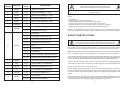
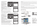
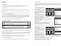
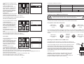
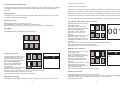
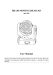
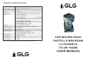
TECHNICAL SPECIFICATIONS
Item:
LED Moving Head Beam 7X12W Osram
Power supply:
AC 100 - 250V, 50/ 60 Hz ~
Power consumption:
150W
Fuse:
250V 3A
Lamp type:
7 Pieces 12W RGBW-in-1 High Power LEDs
Color:
Red: 7x3W LEDs
Green: 7x3W LEDs
Blue: 7x3W LEDs
White: 7x3W LEDs
Yellow: Mixd by Red + Green
Purple: Mixed by Red + Blue
Cyan: Mixed by Green + Blue
Strobe:
Strobe effect by LED flash
Dimmer:
Dimming effect by LED current change
Pan movement:
540 degrees
Tilt movement:
260 degrees
Control mode:
DMX 512 mode, 14 channels
Auto / Sound-active / Master-slave
Dimmension:
304x267x168mm
Packing size:
360x360x445mm
Net weight:
5.8kgs
Gross weight:
6.8kgs
Please note: Every information is subject to change without prior notice.
LED MOVING HEAD
PASTELLO MINI BEAM
14 CHANNELS
7X12W RGBW
USER MANUAL
DJLITE
Dj
Dj
Page 1
CLEANING AND MAINTENANCE
DANGER TO LIFE!
Disconnect from mains before starting maintenance operation!
The operator has to make sure that safety-relating and machine-technical installation are inspected by
- an expert after every four years in the course of an acceptance test.
- a skilled person once a year.
The following points have to be considered during the inspection:
1. All screws used for installing the devices or parts have to be tightly connected and
must not be corroded.
2. There must not be any deformations on the housing, fixations and installation
spots (ceiling, suspension, trussing, etc.)
3. Mechanically moved parts like axles, yokes and others must not showany traces
of wearing (e.g. Material abrading or damages) and must not rotate with unbalance.
4. The electric power supply cables must not show any damages, material fatigue
(e.g. porous cables) or sediments. Furthur instructions depending on the installation
spot and usage have to be adhered by a skilled installer and any safety problems
have to be removed.
CAUTION!
!
The lens should be replaced when it is obviously damaged, so that
its function is impaired, e.g. due to cracks or deep scratches.!
!
The interior of the device need to be cleaned at least annually by an air-jet or a vacuum cleaner.
There are no serviceable parts inside the device except for the lamp and fuse. The
lamp should be replaced when it is damaged, or it is obviously dimmed, or its working
life is exceeded (even if it is undamaged, it might cause explosion when the working
life is exceeded). The LED lamps should be replaced by qualified technicians only!.
Maintenance and service operation can be only carried by authorized dealers.
Should you need any spare parts, please use genuine parts.
Should you have further questions, please contact your dealer.
Page 1
Page 1
- 13 -
DMX
CHANNEL
FUNCTION
DMX
VALUE
1
DIMMER
0 - 255
DIMMER, 0% TO 100%
2
RED
0 - 255
RED COLOR DIMMER (0% - 100%)
3
GREEN
0 - 255
GREEN COLOR DIMMER (0% - 100%)
4
BLUE
0 - 255
BLUE COLOR DIMMER (0% - 100%)
5
WHITE
0 - 255
WHITE COLOR DIMMER (0% - 100%)
6
CUSTOMIZE
0 - 255
CUSTOMIZED COLOR DIMMER (0% - 100%)
0
7
Keep this device away from rain and moisture!
Unplug mains lead before opening the housing!
For your own safety, please read this user manual carefully before your
initially start-up!
DJJ
NO STROBE
STROBE
1 - 255
0
8
CAUTION!
DESCRIPTION
MACRO
- be qualified
- follow the instructions of this manual
- consider this manual to be part of the total product
- keep this manual for the entire service life of the product
- pass this manual on to every further owner or user of the product
- include every supplementary update with the original manual
Before your initial start-up, please make sure that there is no damage caused during
shipment. Should there be any, do not use the device and consult your supplier.
STROBE, SLOW TO FAST
NO MACROS
SAFETY INSTRUCTIONS
1 - 25
FADE TIME BY CONTROLLER ON
26 - 50
FADE TIME BY CONTROLLER OFF
51 - 90
PROGRAM COLOR SELECTION
91 - 130
PULSE
131 - 170
COLOR CHANGE
171 - 210
COLOR FADE
211 - 250
BUILT-IN PROGRAM 1 (UNCONTROLLABLE)
251 - 255
SOUND OPERATION (UNCONTROLLABLE)
This device has left our premises in absolutely perfect condition. In order to maintain
this condition and to ensure a safe operation, it is absolutely necessary for the user
to follow the safety instructions and warning notes written in this user manual.
SPEED
0-255
SPEED FPR CHANNEL 8, SLOW TO FAST
10
PAN
0 - 255
PAN MOVEMENT, 0 - 540 DEGREES
11
PAN FINE
0 - 255
PAN FINE ADJUSTMENT 0 TO 1.75
12
TILT
0 - 255
TILT MOVEMENT, 0 - 200 DEGREES
13
TILT FINE
0 - 255
TILT FINE ADJUSTMENT 0 TO 1
14
RESET
0 - 250
NO FUNCTION
RESET AFTER 3 SECONDS
- 12 -
CAUTION!
Be careful with your operations. With a dangerous voltage you
can suffer a dangerous electric shock when touching the wires!
9
251 - 255
Every person involved with the installation, operation and maintenance of this device
has to
o
o
Important: Damages caused by disregard of this user manual are not subject to warranty. The dealer will not accept liability for any resulting defects or problems.
If the device has been exposed to drastic temperature fluctuation(e.g. after delivery),
do not switch it on immediately. The arising condensation water might damage your
device. Leave the device switched off until it has reached room temperature.
This device falls under protection-class I. The power plug must only be plugged into
a protection-class I outlet. The green or yellowish green conduct should be earthed.
Do not connect this device to a dimmer pack.
Always plug in the power plug least. Check the device and the power cord from time
to time. Make sure that the available voltage is not higher than that stated on the
rear panel. Make sure that the power cord is never crimped or damaged by sharp
edges
Never let the power cord come into contact with other cables! Handle the power cord
and all connections with the mains with particular caution! Only handle the power
cord by the plug. Never pull out the plug by tugging the power cord.
-1-
Reset
CAUTION! EYEDAMAGES!
!
Avoid looking direct to the light source (meant
especially for epileptics)!
!
During the initial start-up some smoke or smell may arise. This is a normal process
and does not necessarily mean that the device is defective.
o
During its operation the housing of the device becomes hot (even as high as 120 C)!
Do not touch the device bare hands.
For replacement, use same type and rating lamp or fuse only.
Always disconnect from the mains, when the device is not in use or beforecleaning it.
For overhead use (mounting height > 100cm), always fix it with at least 1 safety rope
that can hold at least 10 times the weight of the device .
Keep away children and amateurs from the device! Never leave the device running
unattended!
Other useful setting
By the Setup menu you may make many customerized settings,
Please note that damages caused by manual modifications on the device or unauthorized operation by unqualified persons are not subject to warranty.
OPERATING DETERMINATIONS
OPERATION
This device is a moving head wash for creating decorative effects for discotheques,
stages etc. It is allowed to be operated with an alternating current of 100-250V 50/60
Hz, and is designed for indoor use only.
1. Working modes
This device has 3 working modes, DMX mode, Auto mode and Sound mode.
2. Auto mode
Never run the device without a lamp! The lamp must never be ignited if the objectivelens or housing is open, as the discharge lamp might explose and emit a high ultraviolet radiation, which may cause burns.
See page 7.
Do not shake the device. Avoid brute force when installing or operating.
See page 8.
Never lift the device by holding its projector-head, as the mechanics may be damaged. Always hold the device at the transportation handles.
4. DMX mode
When choosing the installation-spot, please make sure that the device is not exposed to extreme heat, moisture or dust. There should not be any cables lying around.
You endanger your own and the safety of others!
3. Sound mode
In DMX mode you can connect more than one device to build a DMX chain and control
all devices via a DMX controller. You need to assign a DMX start address for all devices in the DMX chain. See page 5.
To set the device work in DMX mode, see page 7.
The min. distance between the device and illuminated surface is 1 meter.
DMX CHANNEL
Make sure that the area below the installation place is blocked when rigging, derigging or servicing the device.
-2-
SetUp
OFF
ON
TempSwitchSet
TempSwitchSet
Press the Menu button to back
to the main menu.
TemperatureSet
TemperatureSet
070
070
Press the Menu button once
ScreenSaver
ScreenSaver
ON
ON
again.
Press Up or Down button to
DisplayReverse
DisplayReverse
ON
ON
select the second icon (Setup)
FactorySet
FactorySet
on the second line.
RESET
RESET
Press the Enter button.
YES
Press the Up or Down button
to select the RESET.
Press the Enter button, you will see YES in the right highlighted.
Press the Enter button to save your setting. The device will start to RESET once.
Fader Delay, ON or OFF.
Signal Link, ON or OFF.
Code Wheel, ON or OFF.
Screen Saver, On or OFF.
Factory Defalt Set.
Operate the device only after having familiarized with its functions. Check the device
carefully to see if the housing is firmly closed and with all screws tightly fastened.
SetUp
This device has 14 channels. See next page.
- 11 -
Temperature Switch Set
Press the Menu button to back
to the main menu.
Press the Menu button once
again, you will see one of the
Address RunMode TestMode
6 icons will be highlighted.
Press Up or Down button to
select the second icon on the
second line.
Press the Enter button.
Language SetUp SysInfo
You will see the image on the
right. There are 11 selections,
PanReverse, TiltReverse, etc.
Press the Up or Down button to select the
TempSwitchSet.
Press the Enter button, you will see ON or OFF on
the right will be highlighted.
If you select ON, the Temperature switch will start
working.
Press the Up or Down button to select from ON or
OFF.
Press the Enter button to save your setting.
Press the Menu button to exit to the main menu.
Always fix the device with at least 2 safety ropes. Fix the safety ropes at the correct
holes only.
SetUp
TempSwitchSet
OFF
TemperatureSet
070
ScreenSaver
ON
DisplayReverse
ON
FactorySet
o
The maximum ambient temperature t a=45 C must never be exceeded. Otherwise the
lamp will be switched off and the device will be out of operation for 5 minutes.
Do not permit operation by persons not qualified for operating the device. Most damages are the result of unprofessional operation!
Please use the original packaging if the device is to be transported.
RESET
Please consider that unauthorized modifications on the device are forbidden due to
safety reasons!
SetUp
TempSwitchSet
ON
TemperatureSet
070
ScreenSaver
ON
DisplayReverse
ON
If this device will be operated in any way different to the one described in this manual,
it may suffer damages and the guarantee becomes void. Furthermore, any other operation may lead to dangers like short-circuit, burns, electric shock, etc.
DESCRIPTION
FactorySet
RESET
Notice: It is strongly recommended that you select
the ON for Temperature Switch Set. Otherwise the unit may get too hot!
Temperature Switch Set
SetUp
Press the Menu button to back
to the main menu.
Press the Menu button once
Address RunMode TestMode
again, you will see one of the
6 icons will be highlighted.
Press Up or Down button to
select the second icon on the
second line.
Language SetUp SysInfo
Press the Enter button.
You will see the image on the
right. There are 11 selections,
PanReverse, TiltReverse, etc.
Press the Up or Down button to select the
TemperatureSet.
Press the Enter button, you will see a 3-digits figure in
the right highlighted. The figure is between 050-120.
o
This is the maximum temperature allowed in C.
o
Press the Up or Down button to select from 050 - 120 C.
Press the Enter button to save your setting.
Press the Menu button to exit to the main menu.
TempSwitchSet
OFF
TemperatureSet
070
ScreenSaver
ON
DisplayReverse
ON
FactorySet
RESET
CONTROL PANEL
7. LCD DISPLAY WINDOW
8. DMX SIGNAL
INDICATOR (GREEN)
9. ERROT INDICATOR
(RED)
10. MENU BUTTON
11. UP BUTTON
12. DOWN BUTTON
13. ENTER BUTTON
SetUp
TempSwitchSet
ON
TemperatureSet
070
ScreenSaver
ON
DisplayReverse
ON
FactorySet
RESET
Notice: It is strongly recommended that you select
a proper maximum Temperature. Otherwise the unit may get too hot!
- 10 -
-3-
SETUP
Very important!
1. The lamp
This device uses 7 pieces OSRAM brand 20 watt RGBW-in-1 High Power LEDs,
including 7 pieces red, green, blue, and white color, each 5 watt.
Color mixing
The LEDs in 3 Basic colors (red, green, blue) can create different color mixing.
E.g. Red + Green = Yellow, Red + Blue = Purple, Blue + Green = Cyan, Red + Green +
Blue = White.
With the adjustment of the output of each color, you will get thousands of different
color mixing during DMX operation.
The service life of the LEDs is around 50,000 to 100,000 hours. This means you do
not need to change the LEDs for many years. However, sometimes one of the LEDs
might fail for some reasons. Since the LEDs are connected every 6 of one color into
a series, when one LED fails, the whole series (six LEDs) will not be lit.
When this occurs, fix the device by qualified technicians only.
2. Rigging the device
DANGER OF FIRE!
!
Make sure there is no inflammable material nearby during
installing. Follow the instructions stated on the bottom of
the base of this device.
!
Use 2 clamps to rig the fixture onto a truss. Make sure it is
fixed properly! Ensure the structure (truss) is secure.
!
This device can be installed directly onto a truss, wall or stage floor in any orientation
without altering its operation characteristics.
Use proper bolts to mount the device via its brackets. The brackets should be attached
to the device with proper bolts!
Always use a secondary safety rope that can hold at least 10 times the weight of the
device through the holes on the bottom of the device. Never use the carrying handles
for secondary attachment.
The minimum distance between the device and illuminated surface is 1 meter.There
should not be any flammable materials 10 meters around the device!
3. Connection to mains
Connect the device to mains with the enclosed power plug. The occupation of the
-4-
Pan/Tilt reversed direction
Press the Menu button to back
to the main menu.
Press the Menu button once
again, you will see one of the
Address RunMode TestMode
6 icons will be highlighted.
Press Up or Down button to
select the second icon on the
second line.
Press the Enter button.
Language SetUp SysInfo
You will see the image on the
right. There are 11 selections,
PanReverse, TiltReverse, etc.
Press the Up or Down button to select the
PanReverse or TiltReverse.
Press the Enter button, you will see ON or OFF on
the right will be highlighted. This is the direction of
Pan or Tilt movement.
If you select ON, the movement direction will
be reversed.
Press the Up or Down button to select from ON or OFF.
Press the Enter button to save your setting.
Press the Menu button to exit to the main menu.
SetUp
PanReverse
OFF
TiltReverse
OFF
FaderDelay
ON
SignalLink
ON
CodeWheel
ON
TempSwitchSet
ON
SetUp
PanReverse
OFF
TiltReverse
OFF
FaderDelay
ON
SignalLink
ON
CodeWheel
ON
TempSwitchSet
ON
Display reversed direction
WARNING!
!
The values you selected for the Red, Green, Blue, and White colors will be a mixed
color, and it will be the customized color of the channel 6 for DMX operation! It is
strongly recommended that you select the same color for all devices that will work
together!
Press the Menu button to back
SetUp
to the main menu.
OFF
PanReverse
Press the Menu button once
ON
TempSwitchSet
again, you will see one of the
070
TemperatureSet
6 icons will be highlighted.
Address RunMode TestMode
ON
ScreenSaver
Press Up or Down button to
select the second icon on the
DisplayReverse
ON
second line.
FactorySet
Press the Enter button.
You will see the image on the
RESET
Language SetUp SysInfo
right. There are 11 selections,
PanReverse, TiltReverse, etc.
Press the Up or Down button to select the PanReverse or TiltReverse.
Press the Enter button, you will see ON or OFF on the right will be highlighted. This
is the direction of the Display.
If you select ON, the display direction will be reversed.
Press the Up or Down button to select from ON or OFF.
Press the Enter button to save your setting.
Press the Menu button to exit to the main menu.
-9-
You
DJJwill see the image on the
right.
Press the Up or Down button to
select the Auto mode.
Press the Enter button, you
Address RunMode TestMode
will see Auto1 - Auto8 on the
right. This is the 8 built-in
programs for auto operation.
Press the Enter button, the
Auto1 - Auto8 will be
Language SetUp SysInfo
highlighted.
Press the Up or Down button to
select one of the 8 programs.
Press the Enter button to save your setting.
Press the Menu button to exit to the main menu.
connection cables is as below:
RunMode
DMX
Auto
Auto1
Sound
Pin
Brown
Live
L
Blue
Neutral
N
Yellow / Green
Earth
4. Master-slave / DMX 512 connection
The wires must not come into contact with each other, otherwise
the fixtures will not work at all, or will not work properly.
RunMode
DMX
Auto
Sound
Only use a stereo shielded cable and 3-pin XLR-plugs and connectors in order to
connect the controller with the fixture or one fixture with another.
Occupation of the XLR-connection:
DMX input
XLR mounting
socket
Test mode
TestMode
Press the Menu button to back
to the main menu.
Pan
255
Press the Menu button once
Tilt
155
again, you will see one of the
Address RunMode TestMode
Red
255
6 icons will be highlighted.
Press Up or Down button to
Green
000
select the third icon on the
Blue
155
first line.
Press the Enter button.
White
200
Language SetUp SysInfo
You will see the image on the
right. There are 6 selections,
Pan, Tilt, Red. Green, Blue and White.
Press the Up or Down button to select one of the 6 selections.
Press the Enter button, you will see XXX on the right will be highlighted. This is a
figure between 000 and 255.
Press the Up or Down button to select one of the 000 - 255.
Press the Enter button to save your setting.
Press the Menu button to exit to the main menu.
1=Ground
2=Data (-)
3=Data (+)
DMX output
XLR mounting
socket
If you are using controllers with this occupation, you can connect the DMX-output of
the controller directly with the DMX-input of the 1st device in the DMX-chain. If you
wish to connect DMX-controllers with other XLR-outputs, you need to use adaptercables.
DMX input
XLR mounting
socket
-8-
Internation code
The earth has to be connected.
Sound-activated operation
Press the Menu button to back
to the main menu.
Press the Menu button once
again, you will see one of the
Address RunMode TestMode
6 icons will be highlighted.
Press Up or Down button to
select the second icon on the
first line.
Press the Enter button.
Language SetUp SysInfo
You will see the image on the
right.
Press the Up or Down button to select the Sound mode.
Press the Enter button to save your setting.
Press the Menu button to exit to the main menu.
Cable color
1=Ground
2=Data (-)
3=Data (+)
4: no use
5: no use
DMX output
XLR mounting
socket
Building a serial Master-slave / DMX-chain:
For Master-slave connection, you need to set a device as
the Master device. All other devices will be the slave devices.
120
Connect the DMX-output of the first device (Master) in the
chain with the DMX-input of the second device (the first
slave device). Connect the DMX-output of the second device (the first slave device) with the DMX-input of the third
device (the second slave device). Always connect one
output with the input of the next device until all devices
are connected.
Caution: At the last device, the DMX-cable has to be
terminated with a terminator. Solder a 120 resistor
between Data(-) and Data(+) into a 3-pin XLR-plug and
plug it in the DMX-output of the last device.
-5-
PIN 1
PIN 3
PIN 2
6. Control panel and display
respond to the controller.
The control panel on the base of the device allows you to control the device, including
the DMX start address setting, Master and Slave device setting under M/S mode,
reset, etc.
This device has 14 channels.
Display window
The device use a color LCD display module for displaying your setting. The module
can display both letters and figures.
Buttons for setup
If you set, for example, the starting address to channel 1, the device will use the
channels 1st to 14th for control. The first available channel for the next fixture is 15th.
Please be sure that you do not have any overlapping channels in order to control
each device correctly and independently from any other fixture on the DMX chain.
If 2, 3 or more devices are set with same start address, they will work synchronizely.
For address setting follow this procedure:
MENU button: Main menu selection / Exit.
UP / DOWN: Menu selection / Select your desired value
ENTER: Enter main menu / Save Menu selection or save your desired value
Main Menu
001
Press MENU button, the display will show below:
Address RunMode TestMode
Language SetUp
Language selection
DMX operation selection
SysInfo
Language
Press the Menu button, you will
English
see the main menu as above.
Press the Menu button once
Address RunMode TestMode
again, you will see one of the 6
icons will be highlighted.
Press Up or Down button to
select the first icon on the
second line.
Language SetUp SysInfo
Press the Enter button. You will
see the image on the right.
Press the Up or Down button to select your desired language.
Press the Enter button to save your setting.
Press the Menu button to exit to the main menu.
DMX Address setting
The DMX starting address is defined as the 1st channel from which the device will
-6-
Press the Menu button to back
DmxAddressSet
to the main menu.
Press the Menu button once
again, you will see one of the 6
icons will be highlighted.
Address RunMode TestMode
Press Up or Down button to
select the first icon on the
first line.
Press the Enter button. You will
see XXX. This is a 3-digitsfigure between 001 to 512, i.e. Language SetUp SysInfo
The DMX start address you set
last time.
Press the Up or Down button to select your desired DMX address.
Press the Enter button to save your setting.
Press the Menu button to exit to the main menu.
Press the Menu button to back
to the main menu.
Press the Menu button once
again, you will see one of the 6
Address RunMode TestMode
icons will be highlighted.
Press Up or Down button to
select the second icon on the
first line.
Press the Enter button. You will
Language SetUp SysInfo
see the image on the right.
Press the Up or Down button to
select the DMX mode.
Press the Menu button to exit to the main menu.
RunMode
DMX
14ch
Auto
Sound
Automatic operation
Press the Menu button to back to the main menu.
Press the Menu button once again, you will see one of the 6 icons will be highlighted.
Press Up or Down button to select the second icon on the first line.
Press the Enter button.
-7-