1
Channel Isolated Pulse Input Module
User's Manual
-QD60P8-G
-GX Configurator-CT (SW0D5C-QCTU-E)
• SAFETY PRECAUTIONS •
(Read these precautions before using this product.)
Before using this product, please read this manual and the relevant manuals introduced in this manual
carefully and pay full attention to safety to handle the product correctly.
The precautions given in this manual are concerned with this product only. For the safety precautions of
the programmable controller system, refer to the user’s manual for the CPU module used.
WARNING" and "
CAUTION".
In this manual, the safety precautions are classified into two levels: "
WARNING
Indicates that incorrect handling may cause hazardous conditions,
resulting in death or severe injury.
CAUTION
Indicates that incorrect handling may cause hazardous conditions,
resulting in minor or moderate injury or property damage.
CAUTION" may lead to
Under some circumstances, failure to observe the precautions given under "
serious consequences.
Observe the precautions of both levels because they are important for personal and system safety.
Make sure that the end users read this manual and then keep the manual in a safe place for future
reference.
[Design Precautions]
WARNING
• Do not write data into the "read-only area" in the buffer memory of the intelligent function
module. In addition, do not turn on/off the "Reserved (N/A)" signals among the I/O signals
transferred to/from the programmable controller CPU.
Doing so can malfunction the programmable controller system.
!
CAUTION
• Do not bunch the control wires or pulse input wires with the main circuit or power wires, or install
them close to each other.
They should be installed 150 mm (5.9 inch) or more from each other.
Not doing so could result in noise that may cause malfunction.
A-1
A-1
[Installation Precautions]
!
CAUTION
• Use the programmable controller in an environment that meets the general specifications
contained in the CPU module User's Manual.
Using this programmable controller in an environment outside the range of the general
specifications may cause electric shock, fire, malfunction, and damage to or deterioration of the
product.
• While pressing the installation lever located at the bottom of module, insert the module fixing tab
into the fixing hole in the base unit until it stops. Then, securely mount the module with the fixing
hole as a supporting point.
Improper installation may result in malfunction, breakdown or the module coming loose and
dropping. Securely fix the module with screws if it is subject to vibration during use.
• Tighten the screws within the range of specified torque.
If the screws are loose, it may cause the module to fallout, short circuits, or malfunction.
If the screws are tightened too much, it may cause damage to the screw and/or the module,
resulting in fallout, short circuits or malfunction.
• Be sure to shut off all phases of the external power supply used by the system before mounting
or removing the module.
Not ding so may cause electric shock or damage to the module.
In the system where a CPU module supporting the online module change is used and on the
MELSECNET/H remote I/O stations, modules can be replaced online (during energizing).
However, there are some restrictions on replaceable modules and the replacement procedures
are predetermined for each module.
For details, refer to the chapter of the online module change in this manual.
• Do not install/remove the module to/from the base unit, or the terminal block to/from the module
more than 50 times after the first use of the product. (IEC 61131-2 compliant) Failure to do so
may cause malfunction.
• Do not directly touch the conductive area or electronic components of the module.
Doing so may cause malfunction or failure in the module.
[Wiring Precautions]
WARNING
• Switch all phases of the external power supply off when installing or placing wiring. Not doing so
may cause electric shock or damage to the product.
• Be careful not to let foreign matters such as sawdust or wire chips get inside the module.
These may cause fires, failure or malfunction.
• The top surface of the module is covered with protective film to prevent foreign objects such as
cable offcuts from entering the module when wiring.
Do not remove this film until the wiring is complete.
Before operating the system, be sure to remove the film to provide adequate heat ventilation.
A-2
A-2
[Wiring Precautions]
WARNING
• The cables connected to the module should be placed in a duct or fixed. Not doing so can cause
the module or cables to be damaged when the cables swing, more or are pulled carefully, for
example or to malfunction due to poor cable connection.
A-3
A-3
[Wiring Precautions]
!
CAUTION
• When removing the cable from the module, do not pull the cable.
When disconnecting a cable without a terminal block, unscrew on the part that is connected to
the module.
Pulling the cable that is still connected to the module may cause malfunction or damage to the
module or cable.
• Always ground the shielded cable for the programmable controller.
There is a risk of electric shock or malfunction.
• Use applicable solderless terminals and tighten them with the specified torque.
If any solderless spade terminal is used, it may be disconnected when the terminal screw comes
loose, resulting in failure.
• When wiring, be sure to verify the rated voltage of the product as well as the terminal layout. Fire
or failure may result if incorrect voltage is input or incorrect wiring is performed.
[Startup/Maintenance Precautions]
!
CAUTION
• Do not disassemble or modify the module.
Doing so could cause failure, malfunction, injury or fire.
• Shut off the external power supply for the system in all phases before mounting or removing the
module.
Not doing so may cause failure or malfunction of the module.
In the system where a CPU module supporting the online module change is used and on the
MELSECNET/H remote I/O stations, modules can be replaced online (during energizing).
However, there are some restrictions on replaceable modules and the replacement procedures
are predetermined for each module.
For details, refer to the chapter of the online module change in this manual.
• Do not install/remove the module to/from the base unit, or the terminal block to/from
the module more than 50 times after the first use of the product. (IEC 61131-2 compliant)
Failure to do so may cause malfunction.
• Do not touch the connector while the power is on.
Doing so may cause malfunction.
A-4
A-4
[Startup/Maintenance Precautions]
!
CAUTION
• Shut off the external power supply for the system in all phases before cleaning the module or
retightening the module fixing screws, terminal block screws, and terminal block fixing screws.
Not doing so may cause failure or malfunction of the module.
If the screws are loose, it may cause the module to fallout, short circuits, or malfunction.
If the screws are tightened too much, it may cause damages to the screws and/or the module,
resulting in the module falling out, short circuits or malfunction.
• Always make sure to touch the grounded metal to discharge the electricity charged in the body,
etc., before touching the module.
Failure to do so may cause a failure or malfunctions of the module.
[Disposal Precautions]
!
CAUTION
• When disposing of the product, handle it as industrial waste.
A-5
A-5
• CONDITIONS OF USE FOR THE PRODUCT •
(1) Mitsubishi programmable controller ("the PRODUCT") shall be used in conditions;
i) where any problem, fault or failure occurring in the PRODUCT, if any, shall not lead to any major or
serious accident; and
ii) where the backup and fail-safe function are systematically or automatically provided outside of the
PRODUCT for the case of any problem, fault or failure occurring in the PRODUCT.
(2) The PRODUCT has been designed and manufactured for the purpose of being used in general
industries.
MITSUBISHI SHALL HAVE NO RESPONSIBILITY OR LIABILITY (INCLUDING, BUT NOT LIMITED
TO ANY AND ALL RESPONSIBILITY OR LIABILITY BASED ON CONTRACT, WARRANTY, TORT,
PRODUCT LIABILITY) FOR ANY INJURY OR DEATH TO PERSONS OR LOSS OR DAMAGE TO
PROPERTY CAUSED BY the PRODUCT THAT ARE OPERATED OR USED IN APPLICATION NOT
INTENDED OR EXCLUDED BY INSTRUCTIONS, PRECAUTIONS, OR WARNING CONTAINED IN
MITSUBISHI'S USER, INSTRUCTION AND/OR SAFETY MANUALS, TECHNICAL BULLETINS AND
GUIDELINES FOR the PRODUCT.
("Prohibited Application")
Prohibited Applications include, but not limited to, the use of the PRODUCT in;
y Nuclear Power Plants and any other power plants operated by Power companies, and/or any other
cases in which the public could be affected if any problem or fault occurs in the PRODUCT.
y Railway companies or Public service purposes, and/or any other cases in which establishment of a
special quality assurance system is required by the Purchaser or End User.
y Aircraft or Aerospace, Medical applications, Train equipment, transport equipment such as Elevator
and Escalator, Incineration and Fuel devices, Vehicles, Manned transportation, Equipment for
Recreation and Amusement, and Safety devices, handling of Nuclear or Hazardous Materials or
Chemicals, Mining and Drilling, and/or other applications where there is a significant risk of injury to
the public or property.
Notwithstanding the above, restrictions Mitsubishi may in its sole discretion, authorize use of the
PRODUCT in one or more of the Prohibited Applications, provided that the usage of the PRODUCT is
limited only for the specific applications agreed to by Mitsubishi and provided further that no special
quality assurance or fail-safe, redundant or other safety features which exceed the general
specifications of the PRODUCTs are required. For details, please contact the Mitsubishi
representative in your region.
A-6
A-6
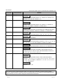
REVISIONS
* The manual number is given on the bottom left of the back cover.
Print Date
Jun., 2002
Feb., 2003
* Manual Number
Revision
SH (NA)-080313E-A First edition
SH (NA)-080313E-B Correction
SAFETY PRECAUTIONS, Section 2.1, Section 2.2, Section 6.2.2,
Section 6.4, Section 6.5, Section 9.1.1
Jun., 2004
SH (NA)-080313E-C
Addition of program example for use on the remote I/O network.
Correction
SAFETY PRECAUTIONS, Section 2.2, Section 4.1, Section 6.4,
Section 6.6, Chapter 7, Section 8.1, Section 8.3.2
Feb., 2006
SH (NA)-080313E-D
Correction
SAFETY PRECAUTIONS, Conformation to the EMC Directive and
Low Voltage Instruction, Section 2.2, Section 4.1, Section 6.2.2
Mar., 2006
SH (NA)-080313E-E
Correction
SAFETY PRECAUTIONS, Section 4.4.2, 7.2, 7.2.1, 7.3, 7.3.1
Sep., 2006
SH (NA)-080313E-F
Correction
SAFETY PRECAUTIONS
Jun., 2007
SH (NA)-080313E-G
Correction
Generic Terms and Abbreviations, Section 2.1, 2.2, 3.1, 4.1, 4.4, 4.5,
5.1.1, 5.2.2, 6.2.1, 6.3 to 6.6, Chapter 8, Section 8.3, INDEX
Jan., 2008
SH (NA)-080313E-H
Correction
Generic Terms and Abbreviations, Section 2.2, 2.3, Section 6.2.2
May, 2008
SH (NA)-080313E-I
Dec., 2010
SAFETY PRECAUTIONS, Compliance with the EMC and Low
Voltage Directives, Generic Terms and Abbreviations, Section 2.1,
2.3, 4.1, 4.4.1, 6.2.1, 6.3.1, 6.3.3, 8.1
SH (NA)-080313E-J Addition of program example for use the utility package.
Correction
Correction
SAFETY PRECAUTIONS, Generic Terms and Abbreviations,
Sections 1.2, 2.1 to 2.3, 3.1, 3.2, 3.5, 4.2, 4.3, 4.5, 5.1.1, 5.1.4, 5.2,
5.6, 6.2.1, 6.3.3, Chapter 7, Sections 7.1, 7.2, 7.2.1, 7.3, 7.3.1, 8.1,
9.1.1, 9.3, Appendix 1
Addition
Sections 7.2.2, 7.3.2
Japanese Manual Version SH-080312-J
This manual confers no industrial property rights or any rights of any other kind, nor does it confer any patent
licenses. Mitsubishi Electric Corporation cannot be held responsible for any problems involving industrial property
rights which may occur as a result of using the contents noted in this manual.
© 2002 MITSUBISHI ELECTRIC CORPORATION
A-7
A-7
INTRODUCTION
Thank you for purchasing the Mitsubishi programmable controller MELSEC-Q Series.
Always read through this manual, and fully comprehend the functions and performance of the Q Series
programmable controller before starting use to ensure correct usage of this product.
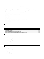
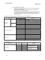
CONTENTS
SAFETY PRECAUSIONS..............................................................................................................................A- 1
CONDITIONS OF USE FOR THE PRODUCT .............................................................................................A- 6
REVISIONS ....................................................................................................................................................A- 7
INTRODUCTION............................................................................................................................................A- 8
CONTENTS....................................................................................................................................................A- 8
USING THIS MANUAL .................................................................................................................................A- 11
COMPLIANCE WITH THE EMC AND LOW VOLTAGE DIRECTIVES......................................................A- 12
GENERIC TERMS AND ABBREVIATIONS ................................................................................................A- 12
COMPONENT LIST ......................................................................................................................................A- 13
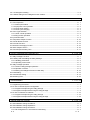
1 OVERVIEW
1- 1 to 1- 4
1.1 Overview................................................................................................................................................... 1- 1
1.2 Features ................................................................................................................................................... 1- 1
2 SYSTEM CONFIGURATION
2- 1 to 2- 7
2.1 Applicable Systems.................................................................................................................................. 2- 1
2.2 Using the QD60P8-G with the Redundant CPU ..................................................................................... 2- 5
2.3 Checking Function Version, Serial Number, and Software Version....................................................... 2- 6
3 SPECIFICATIONS
3- 1 to 3- 14
3.1 Performance Specifications ..................................................................................................................... 3- 1
3.2 List of Functions ....................................................................................................................................... 3- 3
3.3 I/O Signals for Programmable Controller CPU ....................................................................................... 3- 4
3.3.1 List of I/O signals ............................................................................................................................... 3- 4
3.3.2 Details of I/O signals ......................................................................................................................... 3- 5
3.4 Buffer Memory.......................................................................................................................................... 3- 8
3.4.1 List of buffer memory assignments................................................................................................... 3- 8
3.4.2 Details of buffer memory................................................................................................................... 3- 9
3.5 Interface with External Devices .............................................................................................................. 3- 14
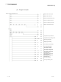
4 SETUP AND PROCEDURE BEFORE OPERATION
4- 1 to 4- 10
4.1 Handling Precautions............................................................................................................................... 44.2 Procedure before Operation .................................................................................................................... 44.3 Part Identification Nomenclature ............................................................................................................. 44.4 Wiring........................................................................................................................................................ 44.4.1 Wiring precautions............................................................................................................................. 44.4.2 Wiring example.................................................................................................................................. 44.5 Setting from GX Developer...................................................................................................................... 4A-8
A-8
1
2
3
4
4
6
8
4.5.1 I/O assignment setting .......................................................................................................................... 4- 8
4.5.2 Switch setting for the intelligent function module................................................................................. 4- 9
5 DETAILS AND SETTING OF FUNCTIONS
5- 1 to 5- 18
5.1 Count Operation....................................................................................................................................... 5- 1
5.1.1 Pulse input method ........................................................................................................................... 5- 1
5.1.2 Input pulse count operation............................................................................................................... 5- 2
5.1.3 Count value reading .......................................................................................................................... 5- 3
5.1.4 Count cycle changing........................................................................................................................ 5- 4
5.2 Count Type Selection............................................................................................................................... 5- 5
5.2.1 Linear counter operation ................................................................................................................... 5- 5
5.2.2 Ring counter operation...................................................................................................................... 5- 7
5.3 Input Pulse Value ..................................................................................................................................... 5- 9
5.4 Comparison Output Function.................................................................................................................. 5- 10
5.5 Counter Reset Function .......................................................................................................................... 5- 12
5.6 Pre-scale Function .................................................................................................................................. 5- 13
5.7 Movement Averaging Function............................................................................................................... 5- 15
5.8 Alarm Output Function ............................................................................................................................ 5- 16
5.9 Count Response Delay Time.................................................................................................................. 5- 17
6 UTILITY PACKAGE (GX Configurator-CT)
6- 1 to 6- 18
6.1 Utility Package Functions ........................................................................................................................ 6- 1
6.2 Installing and Uninstalling the Utility Package ........................................................................................ 6- 2
6.2.1 Handling precautions ........................................................................................................................ 6- 2
6.2.2 Operating environment...................................................................................................................... 6- 4
6.3 Utility Package Operation ........................................................................................................................ 6- 6
6.3.1 Common utility package operations ................................................................................................. 6- 6
6.3.2 Operation overview ........................................................................................................................... 6- 8
6.3.3 Starting the intelligent function module utility .................................................................................. 6- 10
6.4 Initial Setting ............................................................................................................................................ 6- 12
6.5 Auto Refresh Setting............................................................................................................................... 6- 14
6.6 Monitoring/Test........................................................................................................................................ 6- 16
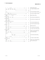
7 PROGRAMMING
7- 1 to 7- 23
7.1 Programming Procedure.......................................................................................................................... 7- 2
7.2 For Use in Normal System Configuration................................................................................................ 7- 3
7.2.1 Program example using the utility package ..................................................................................... 7- 4
7.2.2 Program example without using the utility package......................................................................... 7- 9
7.3 For Use on Remote I/O Network ............................................................................................................ 7- 12
7.3.1 Program example using the utility package .................................................................................... 7- 13
7.3.2 Program example without using the utility package........................................................................ 7- 18
8 ONLINE MODULE CHANGE
8- 1 to 8- 13
8.1 Online Module Change Conditions.......................................................................................................... 88.2 Online Module Change Operations ......................................................................................................... 88.3 Online Module Change Procedure .......................................................................................................... 88.3.1 GX Configurator-CT was used for initial setting ............................................................................... 8A-9
A-9
2
3
4
4
8.3.2 Sequence program was used for initial setting ................................................................................ 8- 8
8.4 Precautions for Online Module Change ................................................................................................. 8- 13
9 TROUBLESHOOTING
9- 1 to 9- 11
9.1 Troubleshooting ....................................................................................................................................... 99.1.1 Confirming the error definitions using system monitor of GX Developer ........................................ 99.2 Error Details.............................................................................................................................................. 99.3 List of Errors ............................................................................................................................................. 9APPENDICES
1
3
5
8
App - 1 to App - 2
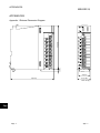
Appendix 1 External Dimension Diagram ................................................................................................App - 1
INDEX
A - 10
Index - 1 to Index - 3
A - 10
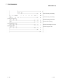
USING THIS MANUAL
Manual Makeup
(1) To know the features and overview of this product (Chapter 1)
Section 1.1 gives the overview and Section 1.2 the features.
(2) To know the system configuration (Chapter 2)
Chapter 2 describes the system configuration, usable programmable controller
CPUs, etc.
(3) To know the system performance and function list (Chapter 3)
Sections 3.1 to 3.4 provides the performance specifications, list of functions, I/O
signals and list of buffer memory. Section 3.5 describes the interface with
external devices.
(4) To know the module installation and setting (Chapter 4)
Chapter 4 describes the wiring example of the module and the setting method
necessary for start of operation.
(5) To know the functions and their setting methods (Chapter 5)
Chapter 5 provides the functions and their setting methods.
(6) To perform initial setting, etc. from the optional utility package
(Chapter 6)
Chapter 6 gives the method for operating the utility package.
(7) To know the example of operating the QD60P8-G using a
sequence program (Chapter 7)
Chapter 7 provides a sequence program example.
(8) To change the module without stopping the system (Chapter 8)
Chapter 8 provides the method for changing the module without stopping the
system (online module change).
(9) To know Error code and corresponding remedy when an error
occurs in the module (Chapter 9)
Chapter 9 provides the troubleshooting and the error code list.
A - 11
A - 11
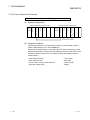
Numeric values used in this manual
• The buffer memory addresses and error codes are represented in decimal.
• The X/Y devices are represented in hexadecimal.
• The values read/written from/to the buffer memory and the values set using the
intelligent function module switches are represented in either of decimal and
hexadecimal. A hexadecimal value is ended by "H".
(Example) 10.........10 Decimal
10H .......16 Hexadecimal
COMPLIANCE WITH THE EMC AND LOW VOLTAGE DIRECTIVES
(1) For programmable controller system
To configure a system meeting the requirements of the EMC and Low Voltage
Directives when incorporating the Mitsubishi programmable controller (EMC and
Low Voltage Directives compliant) into other machinery or equipment, refer to
Chapter 9 "EMC AND LOW VOLTAGE DIRECTIVES" of the QCPU User's
Manual (Hardware Design, Maintenance and Inspection).
The CE mark, indicating compliance with the EMC and Low Voltage Directives, is
printed on the rating plate of the programmable controller.
(2) For the product
For the compliance of this product with the EMC and Low Voltage Directives,
refer to Section 4.4.1 "Wiring precautions".
GENERIC TERMS AND ABBREVIATIONS
Unless specially noted, the following generic terms and abbreviations are used in this
manual.
Generic term/abbreviation
QD60P8-G
Programmable controller CPU
Personal computer
GX Developer
GX Works2
QCPU (Q mode)
Process CPU
Redundant CPU
GX Configurator-CT
Windows Vista
Windows
A - 12
R
XP
R
Details of generic term/abbreviation
Abbreviation for type QD60P8-G Channel Isolated Pulse Input Module.
Generic term for programmable controller CPU on which QD60P8-G can be mounted.
DOS/V-compatible personal computer of IBM PC/AT or its compatible.
R
Product name for the MELSEC programmable controller software package.
Generic term for the Q00JCPU, Q00CPU, Q01CPU, Q02CPU, Q02HCPU, Q06HCPU,
Q12HCPU, Q25HCPU, Q02PHCPU, Q06PHCPU, Q00UJCPU, Q00UCPU, Q01UCPU,
Q12PHCPU, Q25PHCPU, Q12PRHCPU, Q25PRHCPU, Q02UCPU, Q03UDCPU,
Q04UDHCPU, Q06UDHCPU, Q10UDHCPU, Q13UDHCPU, Q20UDHCPU,
Q26UDHCPU, Q03UDECPU, Q04UDEHCPU, Q06UDEHCPU, Q10UDEHCPU,
Q13UDEHCPU, Q20UDEHCPU, Q26UDEHCPU, Q20UDEHCPU and Q100UDEHCPU.
Generic term for Q02PHCPU, Q06PHCPU, Q12PHCPU, Q25PHCPU.
Generic term for the Q12PRHCPU and Q25PRHCPU.
Abbreviation for counter module setting/monitoring tool GX Configurator-CT (SW0D5CQCTU-E).
Generic term for the following:
R
R
Microsoft Windows Vista Home Basic Operating System,
R
R
Microsoft Windows Vista Home Premium Operating System,
R
R
Microsoft Windows Vista Business Operating System,
R
R
Microsoft Windows Vista Ultimate Operating System,
R
R
Microsoft Windows Vista Enterprise Operating System
Generic term for the following:
R
R
Microsoft Windows XP Professional Operating System,
R
R
Microsoft Windows XP Home Edition Operating System
A - 12
COMPONENT LIST
The component list of this product is given below.
Type
Component
Quantity
QD60P8-G
Type QD60P8-G Channel Isolated Pulse Input Module
SW0D5C-QCTU-E
GX Configurator-CT Version 1 (1-license product)
(CD-ROM)
1
SW0D5C-QCTU-EA
GX Configurator-CT Version 1 (Volume-license product)
(CD-ROM)
1
A - 13
1
A - 13
MEMO
A - 14
A - 14
1 OVERVIEW
MELSEC-Q
CHAPTER 1 OVERVIEW
1
1.1 Overview
This User's Manual describes the specifications, handling, wiring and programming
methods of the Channel Isolated Pulse Input Module (QD60P8-G) used with the
MELSEC-Q series programmable controller CPU.
The QD60P8-G counts the input pulse number (speed, rotation speed, instant flux or
similar) and measures the quantity the length, accumulating flux and so forth. Input
pulse value is updated every 10ms. The QD60P8-G updates Accumulating count value
and the pulse number after movement averaging processing or similar (Sampling pulse
number) at intervals of Count cycle setting value.
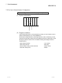
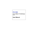
1.2 Features
(1) Wide range of functions
Pulse generator
Input voltage
selection 1)
Pulse edge
selection 2)
Input pulse number
Updated in
count cycle
Pre-scale processing 3)
Movement averaging
processing 4)
Counter reset 11)
Sampling pulse number 5)
Alarm output 8)
1)
Accumulating count value 6)
Updated
every 10ms
Input pulse value 7)
Overflow detection 9) Accumulating counter
comparison flag 10)
Pulse input voltage
A single module accepts the pulse inputs of 5VDC/12 to 24VDC.
2)
Pulse edge selection
It is allowed to select the rise or fall of the input pulses to be counted.
3)
Pre-scale function
The input pulse number is multiplied by any value to convert the pulse
number.
4)
Movement averaging function
The values of Sampling pulse number are averaged by the specified
number of times to calculate the average value.
1-1
1-1
1 OVERVIEW
MELSEC-Q
5)
Sampling pulse number indication
The value obtained by performing pre-scale conversion on the pulse
number entered in Count cycle setting value to the count cycle setting value
is displayed. If the input pulse number is not uniform, movement averaging
processing can be performed to average the input pulse number.
The count range is 0 to 32767.
1
6)
Accumulating count value indication
The accumulating value of Sampling pulse number is displayed in the set
count cycle. The count range is 0 to 99999999, and you can select whether
to use the accumulating counter as the linear counter or ring counter.
7)
Input pulse value indication
The pulse number actually input is displayed every 10ms. Since the input
pulse number is displayed every 10ms, the module can be used as a
counter. (Input pulse value is updated every 10ms. Note this when using
the module as a counter.)
The count range is 0 to 2147483647.
8)
Alarm output
It is allowed to set four setting values, i.e. upper/upper limit value,
upper/lower limit value, lower/upper limit value and lower/lower limit value,
for Sampling pulse number to output alarms.
9)
Accumulating counter overflow detection
If Accumulating count value overflows (exceed 99999999) in the linear
counter mode, the accumulating counter overflow detection flag turns on to
indicate that an overflow error has occurred.
10) Accumulating counter comparison output
If Accumulating count value reaches or exceeds Comparison output setting
value, the accumulating counter comparison flag turns on.
11) Counter reset
Sampling pulse number, Accumulating count value, and Input pulse value
can be reset at any timing.
(2) Counting speed range of the input pulse can be changed
By changing the input filter, the input pulse speed is available within the range 0
to 30kpps.
(3) 8 channels of pulse inputs in one module
One module has 8 channels of pulse inputs to configure a system at low costs.
(4) Channel isolated
The channels are isolated from each other. (Dielectric withstand voltage:
1780VAC for 1 minute)
1-2
1-2
1 OVERVIEW
MELSEC-Q
(5) Online module change
It is possible to change the module without stopping the system.
(6) Easy settings with GX Configurator-CT
The number of sequence programs can be reduced since GX Configurator-CT
(sold separately) allows the channel isolated pulse input module settings on the
dialog box.
Also, GX Configurator-CT simplifies the checking of the module settings and
operation status.
1-3
1-3
1 OVERVIEW
MELSEC-Q
MEMO
1-4
1-4
2 SYSTEM CONFIGURATION
MELSEC-Q
CHAPTER 2 SYSTEM CONFIGURATION
This chapter explains the system configuration of the QD60P8-G.
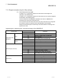
2.1 Applicable Systems
2
This section describes the applicable systems.
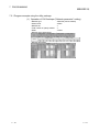
(1) Applicable modules and base units, and No. of modules
(a) When mounted with a CPU module
The table below shows the CPU modules and base units applicable to the
QD60P8-G and quantities for each CPU model.
Depending on the combination with other modules or the number of
mounted modules, power supply capacity may be insufficient.
Pay attention to the power supply capacity before mounting modules, and if
the power supply capacity is insufficient, change the combination of the
modules.
Applicable CPU module
CPU type
No. of modules
CPU model
Q00JCPU
Basic model QCPU
Q00CPU
Q01CPU
1
*
2
Base unit *
Main base unit
Extension base unit
Up to 8
Up to 24
Q02CPU
High Performance
model QCPU
Q02HCPU
Q06HCPU
Up to 64
Q12HCPU
Q25HCPU
Q02PHCPU
Process CPU
Programmable
controller CPU
Q06PHCPU
Q12PHCPU
Up to 64
Q25PHCPU
Redundant CPU
Q12PRHCPU
Q25PRHCPU
Q00UJCPU
Q00UCPU
Q01UCPU
Q02UCPU
3
Up to 53 *
Up to 8
Up to 24
Up to 36
Q03UDCPU
Universal model QCPU
Q04UDHCPU
Q06UDHCPU
Q10UDHCPU
Up to 64
Q13UDHCPU
Q20UDHCPU
Q26UDHCPU
: Applicable,
2-1
: N/A
2-1
2 SYSTEM CONFIGURATION
MELSEC-Q
Applicable CPU module
CPU type
1
CPU model
No. of modules *
2
Base unit *
Main base unit Extension base unit
Q03UDECPU
Q04UDEHCPU
Q06UDEHCPU
2
Q10UDEHCPU
Programmable
controller CPU
Universal model QCPU
Q13UDEHCPU
Up to 64
Q20UDEHCPU
Q26UDEHCPU
Q50UDEHCPU
Q100UDEHCPU
Safety CPU
QS001CPU
*4
N/A
Q06CCPU-V
C Controller module
Q06CCPU-V-B
Up to 64
Q12DCCPU-V
: Applicable, : N/A
*1: Limited within the range of I/O points for the CPU module.
*2: Can be installed to any I/O slot of a base unit.
*3: Use the QD60P8-G module whose serial No. (first five digits) is 09012
or later.
*4: The safety CPU cannot be connected with extension base units.
REMARK
For the use of the C Controller module, refer to C Controller Module User's Manual.
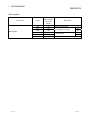
(b) Mounting to a MELSECNET/H remote I/O station
The table below shows the network modules and base units applicable to
the QD60P8-G and quantities for each network module model.
Depending on the combination with other modules or the number of
mounted modules, power supply capacity may be insufficient.
Pay attention to the power supply capacity before mounting modules, and if
the power supply capacity is insufficient, change the combination of the
modules.
2
Applicable network
module
QJ72LP25-25
QJ72LP25G
QJ72LP25GE
QJ72BR15
1
No. of modules *
Base unit *
Main base unit of
Extension base unit of
remote I/O station
remote I/O station
Up to 64
: Applicable,
*1: Limited within the range of I/O points for the network module.
*2: Can be installed to any I/O slot of a base unit.
: N/A
REMARK
The Basic model QCPU or C Controller module cannot create the MELSECNET/H
remote I/O network.
2-2
2-2
2 SYSTEM CONFIGURATION
MELSEC-Q
(2) Support of the multiple CPU system
When using the QD60P8-G in a multiple CPU system, refer to the following
manual first.
• QCPU User's Manual (Multiple CPU System)
(a) Supported QD60P8-G
The function version of the QD60P8-G has been "C" from the first release,
supporting the multiple CPU system.
(b) Intelligent function module parameters
Write intelligent function module parameters only to the control CPU of the
QD60P8-G.
(3) Support of online module change
The function version of the QD60P8-G has been "C" from the first release,
supporting online module change.
For details, refer to CHAPTER 8.
2-3
2-3
2 SYSTEM CONFIGURATION
MELSEC-Q
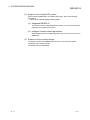
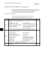
(4) Supported software packages
Relation between the system containing the QD60P8-G and software package is
shown in the following table.
GX Developer is necessary when using the QD60P8-G.
Software Version
GX Developer
Q00J/Q00/Q01CPU
Single CPU system
Version 7 or later
GX Configurator-CT
GX Works2
Version 1.10N or
Multiple CPU system
Version 8 or later
later
Q02/Q02H/Q06H/
Single CPU system
Version 4 or later
Version 1.08J or
Q12H/Q25HCPU
Multiple CPU system
Version 6 or later
Version 1.14Q or
Single CPU system
Version 8.68W or
later
Q02PH/Q06PHCPU
Multiple CPU system
Single CPU system
Q12PH/Q25PHCPU
Multiple CPU system
Q12PRH/Q25PRHCPU
Redundant system
Q00UJ/Q00U/
Single CPU system
Q01UCPU
Multiple CPU system
Q02U/Q03UD/Q04UDH/
Single CPU system
Q06UDHCPU
Multiple CPU system
Single CPU system
Q10UDH/Q20UDHCPU
Multiple CPU system
Single CPU system
Q13UDH/Q26UDHCPU
Multiple CPU system
Q03UDE/Q04UDEH/
Single CPU system
Q06UDEH/Q13UDEH/
Multiple CPU system
Q26UDEHCPU
Single CPU system
Q10UDEH/Q20UDEHCPU
Multiple CPU system
Q50UDEH/Q100UDEHCPU
Single CPU system
Multiple CPU system
If installed in a MELSECNET/H remote I/O station
later
later
Not supported
Version 7.10L or later
Version 8.45X or
Version 1.16S or
later
later
Version 8.78G or
later
Version 8.48A or
later
Version 8.78G or
later
Version 8.62Q or
later
Version 1.25AB or
Version 1.08J or
later
later
Version 8.68W or
later
Version 8.78G or
later
Not supported
Version 6 or later
Not supported
Version 1.14Q or
later
Version 1.31H or
later
Not supported
POINT
Depending on the version of GX Configurator-CT, CPU modules and functions of
the QD60P8-G vary.
2-4
2-4
2 SYSTEM CONFIGURATION
MELSEC-Q
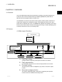
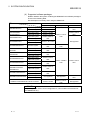
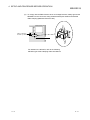
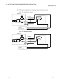
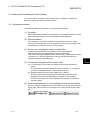
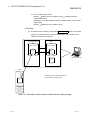
2.2 Using the QD60P8-G with the Redundant CPU
The following describes the use of the QD60P8-G with Redundant CPU.
(1) GX Configurator-CT
GX Configurator-CT cannot be used when accessing the Redundant CPU via an
intelligent function module on the extension base unit from GX Developer.
Connect a personal computer to the Redundant CPU with a communication path
indicated below.
1
2
Main base unit
Extension base unit
(GX Configurator-CT cannot be used.)
2-5
1
Direct connection to the CPU
2
Connection through an intelligent function module on the main base unit
(Through Ethernet module, MELSECNET/H module, or CC-Link module)
2-5
2 SYSTEM CONFIGURATION
MELSEC-Q
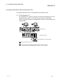
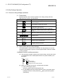
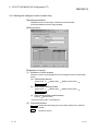
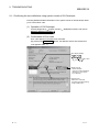
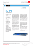
2.3 Checking Function Version, Serial Number, and Software Version
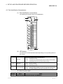
(1) Checking the function version and serial number of the QD60P8-G
The serial number and function version of the QD60P8-G are described on the
rating plate, on the front of the module, or displayed in the System monitor of GX
Developer.
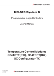
(a) Checking the rating plate on the side of the QD60P8-G
Serial No. (first 5 digits)
Function version
Relevant regulation standards
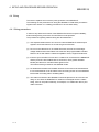
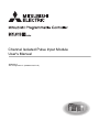
(b) Checking the front of the module
The serial number and function version on the rating plate is shown on the
front (at the bottom) of the module.
101219000000000-C
Function version
Serial No.
REMARK
The serial number is displayed on the front of the module from December 2008
production. Products manufactured during the switching period may not have the
serial number on the front of the module.
2-6
2-6
2 SYSTEM CONFIGURATION
MELSEC-Q
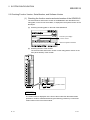
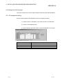
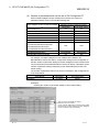
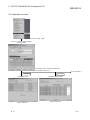
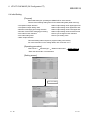
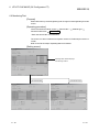
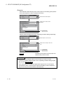
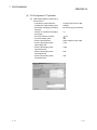
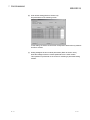
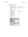
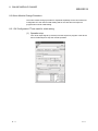
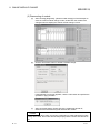
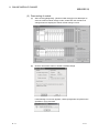
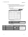
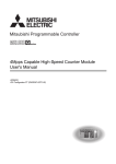
(c) Checking the System monitor (Product Information List)
To display the System monitor, select [Diagnostics] [System monitor] and
click the Product Information List button of GX Developer.
Function version
Serial No.
Product No.
1) Displaying the product number.
Since the QD60P8-G does not support the display function, "-" is
displayed in the "Product No." field.
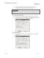
POINT
The serial number displayed in the Product Information List dialog box of GX
Developer may differ from that on the rating plate and on the front of the module.
• The serial number on the rating plate and front part of the module indicates the
management information of the product.
• The serial number displayed in the Product Information List dialog box of GX
Developer indicates the function information of the product.
The function information of the product is updated when a new function is
added.
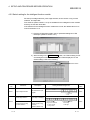
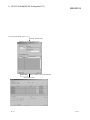
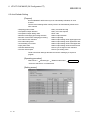
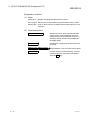
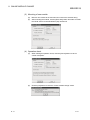
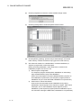
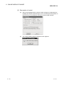
(2) Checking the software version of GX Configurator-CT
The software version of GX Configurator-CT can be checked by selecting [Help]
[Product information] of GX Developer.
Software version
2-7
2-7
3 SPECIFICATIONS
MELSEC-Q
CHAPTER 3 SPECIFICATIONS
This chapter explains the performance specifications of the QD60P8-G, the I/O signals
for the programmable controller CPU, and the specifications of the buffer memory.
For the general specifications of the QD60P8-G, refer to the User's Manual of the used
CPU module.
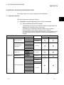
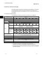
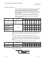
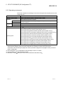
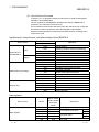
3.1 Performance Specifications
The following table indicates the performance specifications of the QD60P8-G.
3
Model name
QD60P8-G
Item
Counting speed switch settings*1
30kpps
Number of I/O occupied points
10kpps
1kpps
Number of channels
Count input
signal
50pps
10pps
1pps
0.1pps
8 channels
Phase
1-phase input
Signal level
5VDC/12 to 24VDC
Input derating
Refer to the derating chart (Next page)
Counting speed
(Max.) *2
30kpps
10kpps
1kpps
100pps
50pps
10pps
1pps
0.1pps
: 16-bit binary (0 to 32767)
Sampling pulse number
Accumulating count value : 32-bit binary (0 to 99999999)
: 32-bit binary (0 to 2147483647)
Input pulse value
Counting range
Counter
100pps
32 points (I/O assignment: 32 points for intelligent function module)
Count type
Linear counter method, ring counter method
Minimum count
pulse width
(Duty ratio 50%)
33.4 s
100 s
1ms
10ms
20ms
100ms
1s
10s
16.7 16.7
s s
50 50
s s
0.5 0.5
ms ms
5 5
ms ms
10 10
ms ms
50 50
ms ms
0.5 0.5
s s
5s 5s
For 1 min at 1500VAC between AC external connecting terminals and general grounding
For 1 min at 500VAC between DC external connecting terminals and general grounding
For 1 min at 1780VAC between channels
Dielectric withstand voltage
Insulation resistance
5MΩ or more at 500VDC between AC external connecting terminals and general grounding
Connected terminal
18 points terminal block
Applicable wire size
0.3 to 0.75mm
Applicable solderless terminals
Internal current consumption
(5VDC)
Weight
External dimensions
2
R1.25-3 (A solderless terminals with sleeves cannot be used.)
0.58A
0.17kg
27.4 (1.08) (W) X 98 (3.86) (H) X 90 (3.54) (D) [mm (in.)]
*1: To change the counting speed, use the intelligent function module switch.
(For details, refer to "Section 4.5.2 Switch setting for intelligent function module".)
*2: The counting speed is affected by the rise/fall time of pulses. The countable counting speeds
are indicated in the table on the next page. Note that counting the pulses of long rise/fall time
may result in miscounting.
3-1
3-1
3 SPECIFICATIONS
MELSEC-Q
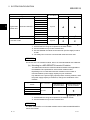
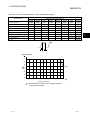
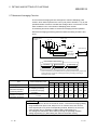
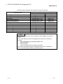
<Rise/Fall time and the corresponding counting speed switch settings>
Counting speed switch settings
Rise/Fall Time
30kpps
10kpps
1kpps
100pps
50pps
10pps
1pps
0.1pps
t = 8.4µs or less
30kpps
10kpps
1kpps
100pps
50pps
10pps
1pps
0.1pps
t = 25µs or less
10kpps
10kpps
1kpps
100pps
50pps
10pps
1pps
0.1pps
t = 250µs or less
-
1kpps
1kpps
100pps
50pps
10pps
1pps
0.1pps
t = 2.5ms or less
-
-
100pps
100pps
50pps
10pps
1pps
0.1pps
t = 5ms or less
-
-
-
50pps
50pps
10pps
1pps
0.1pps
t = 25ms or less
-
-
-
-
10pps
10pps
1pps
0.1pps
t = 250ms or less
-
-
-
-
-
1pps
1pps
0.1pps
t = 2.5s or less
-
-
-
-
-
-
0.1pps
0.1pps
t = 5s
-
-
-
-
-
-
-
0.05pps
t
t
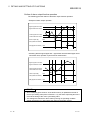
<Derating Chart>
( )
100
90
80
3
ON
ratio 70
30VDC
60
50
40
0
10
20
30
40
50
55 ( )
Ambient temparature
3: "ON" indicates the status where voltage is applied
to pulse input terminals.
3-2
3-2
3
3 SPECIFICATIONS
MELSEC-Q
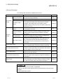
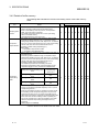
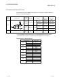
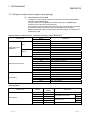
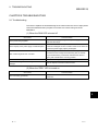
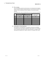
3.2 List of Functions
The following table indicates the QD60P8-G functions.
Name
Details
Linear counter function
Ring counter function
Accumulating
counter
This function counts from 0 to 99999999 and detects an overflow
when the count range is exceeded.
This function repeats counting between 0 and 99999999.
Reference
Section 5.2.1
Section 5.2.2
This function turns on Accumulating counter comparison flag (X0
Comparison output
function
to X17) when Accumulating count value reaches or exceeds
Comparison output setting value. (Accumulating counter
Section 5.4
comparison flag (X0 to X17) turns off by Comparison signal reset
request (Y10 to Y17).)
Count cycle change
This function changes the count cycle of Sampling pulse number
function
or Accumulating count value.
Movement averaging
function
This function performs movement averaging processing by the
specified number of times if there are variations in Sampling
Section 5.7
pulse number.
Sampling
counter
Section 5.1.4
Pre-scale function
This function converts the number of pulses by multiplying the
number of input pulses by any setting number.
Section 5.6
This function sets the upper/upper limit value, upper/lower limit
Alarm output function
value, lower/upper limit value and lower/lower limit value for
Sampling pulse number converted by the pre-scale function to
Section 5.8
output alarms.
This function resets Sampling pulse number, Accumulating count
Counter reset function
value, or Input pulse value. A reset can be made at any timing.
Section 5.5
This function selects whether the rise or fall of an input pulse will
Pulse edge selection function
be used for counting. (This setting can be made for each channel
Section 4.5.2
using the intelligent function module switch.)
This function starts input pulse count operation when Count
Count enable function
enable (Y18 to Y1F) is turned on.
Section 5.1.2
This function changes the module without stopping the system.
Online module change function
(Perform an online module change according to the messages of
Chapter 8
GX Developer.)
This function uses the utility package (GX Configurator-CT) to
Utility function
perform initial setting, auto refresh setting, monitor/test or similar
Chapter 6
from within the software without using sequence programs.
POINT
The above functions can be used in combination.
However, the linear counter function and ring counter function cannot be used
together.
Please select either of them.
3-3
3-3
3 SPECIFICATIONS
MELSEC-Q
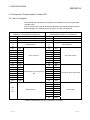
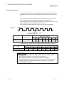
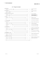
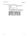
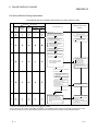
3.3 I/O signals for Programmable Controller CPU
3.3.1 List of I/O signals
The following table indicates the I/O signals of the QD60P8-G for the programmable
controller CPU.
The I/O numbers (X/Y) and I/O addresses indicated in this chapter and later assume
that the QD60P8-G is installed on the I/O slot No. 0 of the main base unit.
Input signal (Signal direction:
QD60P8-G
programmable controller CPU)
Output signal (Signal direction:
programmable controller CPU
QD60P8-G)
Device No.
Signal name
Device No.
Signal name
X0
Module READY
Y0
Reserved (N/A) *
X1
Operating condition setting complete flag
Y1
Operating condition setting request flag
Reserved (N/A) *
Y2
to
Y7
Reserved (N/A) *
X2
to
X7
X8
CH1
Y8
CH1
X9
CH2
Y9
CH2
XA
CH3
YA
CH3
XB
CH4
YB
CH4
XC
CH5
YC
CH5
XD
CH6
YD
CH6
XE
CH7
YE
CH7
XF
CH8
YF
CH8
X10
CH1
Y10
CH1
X11
CH2
Y11
CH2
X12
CH3
Y12
CH3
X13
CH4
Y13
CH4
X14
CH5
Y14
CH5
X15
CH6
Y15
CH6
X16
CH7
Y16
CH7
X17
CH8
Y17
CH8
Y18
CH1
Y19
CH2
Y1A
CH3
X18
to
X1F
Error occurrence
Accumulating counter comparison
flag
Reserved (N/A) *
Y1B
CH4
Y1C
CH5
Y1D
CH6
Y1E
CH7
Y1F
CH8
Error reset request
Comparison signal reset request
Count enable
*: Write is inhibited to the I/O (X/Y) reserved for the system.
3-4
3-4
3 SPECIFICATIONS
MELSEC-Q
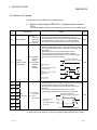
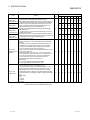
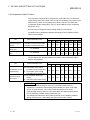
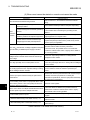
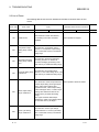
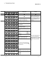
3.3.2 Details of I/O signals
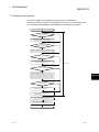
The I/O signals of the QD60P8-G are detailed below.
(1) Details of input signals (QD60P8-G
CPU)
programmable controller
The following table indicates the on/off timings and functions of the input signals.
Device
No.
X0
X1
Details
Initial
value
*1
• This signal judges whether the QD60P8-G is normal or
abnormal in the sequence program. This signal turns on when
the module starts normally at power-on or reset operation.
• This signal turns off at occurrence of a watch dog timer error.
OFF
Signal name
OFF: Not
Prepared/
Watch dog
timer error
ON : Prepared
Module READY
OFF: Operating
condition
setting
ON : Operating
condition
setting
complete
Operating
condition setting
completed flag
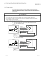
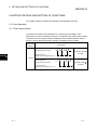
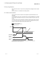
• This signal is used as an interlock for turning on/off Operating
condition setting request flag (Y1) when the function, such as
the comparison output function, is selected or the setting value
is changed.
• When this signal is off, input pulses are not counted.
• After confirming that the operating condition setting is
completed (this signal has turned on), turn on Count enable
(Y18 to Y1F) to start pulse counting.
Executed by QD60P8-G
Executed by sequence program
ON
Module READY
(X0)
OFF
Operating condition setting
completed flag
(X1)
OFF
Operating condition setting
request flag
(Y1)
OFF
Count enable
(Y18 to Y1F)
OFF
ON
ON
ON
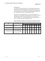
• This signal turns on if an error exists in the overflow detection
or initial setting data. (The details of the error can be confirmed
from the "system monitor" screen of GX Developer.)
• This signal turns off when Error reset request (Y8 to YF) is
turned on.
• "Error code" is stored into the buffer memory of the
corresponding channel (refer to Section 3.4.2 for details).
X8
CH1
X9
CH2
XA
CH3
XB
CH4
XC
CH5
CH6
Error occurrence
(X8 to XF)
OFF
XD
OFF
XE
CH7
Error reset request
(Y8 to YF)
XF
CH8
Error
occurrence
OFF: No Error
occurrence
ON : Error
occurrence
OFF
Executed by QD60P8-G
Executed by sequence program
ON
OFF
ON
Error code is read during this period.
*1: Initial value set at power-on or when the programmable controller CPU is reset.
3-5
3-5
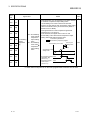
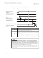
3 SPECIFICATIONS
Device
No.
MELSEC-Q
Signal name
Initial
value
*1
Details
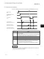
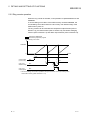
X15
• This signal turns on if "Accumulating count value" reaches
or exceeds "Comparison output setting value".
"Accumulating count value" is stored into the buffer
memory for each channel. Set "Comparison output setting
value" to the buffer memory for each channel. (Refer to
CH2
Section 3.4.2 for details.)
• This signal remains on until Comparison signal reset
request (Y10 to Y17) turns on.
CH3
• Once turned off, this signal does not turn on until
OFF: Accumulating
Accumulating count value reaches Comparison output
count value
setting value again after it has been reset.
Comparison
Executed by QD60P8-G
CH4 Accumulating
output setting
Executed by sequence program
value
counter
Count cycle
ON : Accumulating
comparison
Accumulating count value
setting value
count value
CH5 flag
Comparison
output setting
Comparison output
value
setting value
CH6
X16
CH7
X10
X11
X12
X13
X14
X17
CH1
CH8
Accumulating counter
OFF
comparison flag
(X10 to X17)
Comparison signal
OFF
reset request
(Y10 to Y17)
OFF
ON
ON
*1: Initial value set at power-on or when the programmable controller CPU is reset.
3-6
3-6
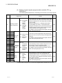
3 SPECIFICATIONS
MELSEC-Q
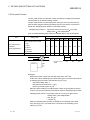
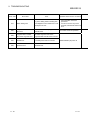
(2) Details of output signals (programmable controller CPU
QD60P8-G)
The following table indicates the on/off timings and functions of the output signals.
Device
No.
Y1
Details
Initial
value
*1
• This signal turns on to make "Comparison output setting
value" and other setting data of the buffer memory valid.
• When this signal turns on, the setting data are reflected
on the module.
• When this signal turns on, "Sampling pulse number",
"Accumulating count value", or "Input pulse value"
assigned to the buffer memory for each channel is reset.
• When this signal is turned on in the sequence program,
it should be kept on for longer than 10ms.
• For details on the on/off timing of this signal, refer to the
item of the input signal (X1).
OFF
Signal name
Operating condition
setting request flag
Y8
Y9
YA
YB
YC
YD
YE
YF
Y10
Y11
Y12
Y13
Y14
Y15
Y16
Y17
Y18
Y19
Y1A
Y1B
Y1C
Y1D
Y1E
Y1F
CH1
CH2
CH3
CH4
CH5
CH6
CH7
CH8
CH1
CH2
CH3
CH4
CH5
CH6
CH7
CH8
CH1
CH2
CH3
CH4
CH5
CH6
CH7
CH8
Error reset
request
OFF: No operating
condition
setting
request
ON : Operating
condition
setting
request
•
OFF: No Error reset
request
ON : Error reset
•
request
OFF: No
Comparison
signal reset
Comparison
request
signal reset
ON : Comparison
request
signal reset
request
Count
enable
OFF: Count
operation
stop
ON : Count
operation
start
If the error occurrence signal (X8 to XF) has turned on
due to the error occurrence, turning on this signal clears
that error.
For details on the on/off timing of this signal, refer to the
item of the input signal (X8 to XF).
OFF
• If Accumulating counter comparison flag (X10 to X17)
has turned on, turning on this signal clears
Accumulating counter comparison flag (X10 to X17).
• For details on the on/off timing of this signal, refer to the
item of the input signal (X10 to X17).
OFF
• This signal turns on when count operation is started.
• When this signal turns on, the count operation of
"Sampling pulse number", "Accumulating count value",
or "Input pulse value" assigned to the buffer memory for
each channel is started.
• For details on the on/off timing of this signal, refer to the
item of the input signal (X1).
OFF
*1: Initial value set at power-on or when the programmable controller CPU is reset.
3-7
3-7
3 SPECIFICATIONS
MELSEC-Q
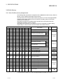
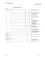
3.4 Buffer Memory
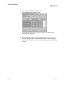
3.4.1 List of buffer memory assignments
The following table indicates the assignment of the QD60P8-G buffer memory. Refer to
Section 3.4.2 for details of the buffer memory areas.
The initial values are set to the buffer memory at power-on or when the programmable
controller CPU is reset. (When power is turned off, the setting values in the buffer
memory are not retained.)
The sequence program or programmable controller CPU's auto refresh function,
reads/writes the buffer memory contents.
The settings are reflected on the module by turning on Operating condition setting
request flag (Y1) after the data have been written to the buffer memory.
Buffer memory address
Initial
Setting details
value
CH1
CH2
CH3
CH4
CH5
CH6
CH7
CH8
0
32
64
96
128
160
192
224
Sampling pulse number
1
33
65
97
129
161
193
225
Comparison output selection
2
34
66
98
130
162
194
226
3
35
67
99
131
163
195
227
4
36
68
100
132
164
196
228
Movement averaging processing selection
5
37
69
101
133
165
197
229
Number of movement averaging processing
Comparison output setting value
6
38
70
102
134
166
198
230
Pre-scale function selection
7
39
71
103
135
167
199
231
Pre-scale setting value
8
40
72
104
136
168
200
232
9
41
73
105
137
169
201
233
10
42
74
106
138
170
202
234
11
43
75
107
139
171
203
235
12
44
76
108
140
172
204
236
Overflow detection flag
13
45
77
109
141
173
205
237
Counter reset request
14
46
78
110
142
174
206
238
Carry over detection flag
Accumulating count value
Input pulse value
15
47
79
111
143
175
207
239
Carry over reset request
16
48
80
112
144
176
208
240
Error code
17
49
81
113
145
177
209
241
Read/Write
Read only
(L)
(H)
Read/Write
enabled
(L)
(H)
Read only
(L)
(H)
Alarm output selection
0
Read/Write
enabled
Read only
Read/Write
enabled
Read only
Read/Write
enabled
18
50
82
114
146
178
210
242
Alarm output flag
19
51
83
115
147
179
211
243
Alarm output setting value upper/upper limit
Read only
20
52
84
116
148
180
212
244
Alarm output setting value upper/lower limit
21
53
85
117
149
181
213
245
Alarm output setting value lower/upper limit
Read/Write
22
54
86
118
150
182
214
246
Alarm output setting value lower/lower limit
enabled
23
55
87
119
151
183
215
247
Count cycle change function selection
24
56
88
120
152
184
216
248
Count cycle setting value
25
to
57
to
89
to
121
to
153
to
185
to
217
to
249
to
Reserved (N/A)
31
63
95
127
159
191
223
255
*1: Initial value set at power-on or when the programmable controller CPU is reset.
3-8
3-8
3 SPECIFICATIONS
MELSEC-Q
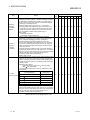
3.4.2 Details of buffer memory
The following table indicates the functions and setting values of the buffer memory
areas.
Item
Sampling pulse
number
Comparison
output selection
• Stores the pulse number obtained by converting the input pulses
into the unit pulse number using the pre-scale function.
• When Count enable (Y18 to Y1F) turns on, count operation
starts. The count range is 0 to 32767.
• The update timing is the interval set in "Count cycle setting
value" of the buffer memory.
(The initial value of the count cycle is 1s.)
• Set whether the comparison output function is valid or invalid.
• If the setting value is other than 0 or 1, a comparison output
setting range outside error (Error code: 200) occurs. To clear the
error, turn on Error reset request (Y8 to YF) of the corresponding
channel. After this, set a correct value and then turn on
Operating condition setting request flag (Y1).
[Setting value]
0: Comparison output function invalid
1: Comparison output function valid
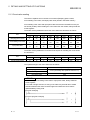
• Set the value to be compared with "Accumulating count value" of
the buffer memory.
• If the setting value is outside the range, a comparison output
setting range outside error (Error code: 200) occurs. To clear the
error, turn on Error reset request (Y8 to YF) of the corresponding
channel. After this, set a correct value and then turn on
Operating condition setting request flag (Y1).
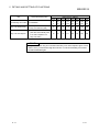
• The relationships between Accumulating count value,
Comparison output setting value, and Accumulating counter
comparison flag (X10 to X17) on/off are as indicated below.
Setting value and Accumulating count
value
Setting value
Comparison
output setting
value
Initial
Buffer memory address
value CH1 CH2 CH3 CH4 CH5 CH6 CH7 CH8
Details
OFF
Setting value = Accumulating count
value
ON
Accumulating count
value
0
32
64
96
128 160 192 224
0
1
33
65
97
129 161 193 225
0
2
3
34
35
66
67
98
99
130 162 194 226
131 163 195 227
Accumulating counter
comparison flag
(X10 to X17)
Accumulating count
value
Setting value
0
ON
• Accumulating counter comparison flag (X10 to X17) is cleared by
turning on Comparison signal reset request (Y10 to Y17) of the
corresponding channel.
• When the accumulating counter is operating as a linear counter,
Accumulating counter comparison flag (X10 to X17) that was
turned off once does not turn on until the accumulating count
value reaches Comparison output setting value again after it has
been reset. When the accumulating counter is operating as a
ring counter, the flag turns on when Accumulating count value
reaches Comparison output setting value again in the ring
processing.
[Setting range: 0 to 99999999]
*: Refer to Section 9.3 for details of the error codes.
3-9
3-9
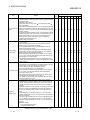
3 SPECIFICATIONS
Item
Movement
averaging
processing
selection
Number of
movement
averaging
processing
Pre-scale
function selection
MELSEC-Q
Initial
Buffer memory address
value CH1 CH2 CH3 CH4 CH5 CH6 CH7 CH8
Details
• When "movement averaging processing" is set in Movement
averaging processing selection, movement averaging processing
is performed on "Sampling pulse number" of the buffer memory
by the number of times set in "Number of movement averaging
processing" of the buffer memory.
• When the setting value is other than 0 or 1, a movement
averaging setting range outside error (Error code: 300) occurs.
To clear the error, turn on Error reset request (Y8 to YF) of the
corresponding channel. After this, set a correct value and then
turn on Operating condition setting request flag (Y1).
[Setting value]
0: Sampling processing
1: Movement averaging processing
• Set the number of times to perform movement averaging
processing on "Sampling pulse number" of the buffer memory.
• When "movement averaging processing" is selected in
"Movement averaging processing selection" of the buffer
memory, the initial value of this buffer memory is "0". Therefore,
if you run the programmable controller CPU without setting the
value, a movement averaging setting range outside error (Error
code: 300) will occur.
• If the setting value is outside the range, a movement averaging
setting range outside error (Error code: 300) occurs. To clear the
error, turn on Error reset request (Y8 to YF) of the corresponding
channel. After this, set a correct value and then turn on
Operating condition setting request flag (Y1).
[Setting range: 2 to 60]
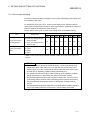
• The pre-scale function converts the input pulse number per count
cycle into the unit pulse number when the weight per pulse is a
fraction, and stores the result of conversion into "Sampling pulse
number" of the buffer memory. The following operation formula is
used at this time.
Sampling pulse number =
Input pulse value per count cycle
Pre-scale setting
value
Unit magnification
The converted sampling pulse number is rounded down to the
decimal point.
Pre-scale function selection
(Unit magnification)
Pre-scale function invalid
0
4
36
68
100 132 164 196 228
0
5
37
69 101 133 165 197 229
0
6
38
70 102 134 166 198 230
Setting value
0
1
1
0.1
2
0.01
3
0.001
4
0.0001
5
If the setting value is other than the above values, a pre-scale
setting range outside error (Error code: 400) occurs. To clear the
error, turn on Error reset request (Y8 to YF) of the corresponding
channel. After this, set a correct value and then turn on
Operating condition setting request flag (Y1).
*: Refer to Section 9.3 for details of Error code.
3 - 10
3 - 10
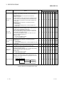
3 SPECIFICATIONS
Item
MELSEC-Q
Details
• Set the pre-scale setting value.
• "Sampling pulse number" of the buffer memory with the following
operation formula:
Sampling pulse number =
Input pulse value per count cycle
Pre-scale setting value
Unit magnification
Note that if Pre-scale setting value is "0", the displayed sampling
Pre-scale setting
pulse number becomes 0 from the above operation formula, and
therefore, it seems as if pulses are not counted although they are
value
actually counted.
• If the setting value is outside the range, a pre-scale setting range
outside error (Error code: 400) occurs. To clear the error, turn on
Error reset request (Y8 to YF) of the corresponding channel.
After this, set a correct value and then turn on Operating
condition setting request flag (Y1).
[Setting range: 0 to 32767]
• Stores the accumulating value of "Sampling pulse number" of the
buffer memory.
• The accumulating count value can be used when either the
linear counter or ring counter is selected.
• The accumulating count range is 0 to 99999999 for both the
linear counter and ring counter.
• If the accumulating count value exceeds 99999999 when the
Accumulating
accumulating counter is used as the linear counter, "Overflow
count value
detection flag" of the buffer memory turns on.
• When Operating condition setting request flag (Y1) is turned on
or "1" is set in "Counter reset request" of the buffer memory, the
accumulating count value is reset.
• The update timing is the same as the cycle of Sampling pulse
number. (It is the interval set in "Count cycle setting value" of the
buffer memory.)
• Stores the actually entered pulse number.
• This value is not converted into the unit pulse number by the prescale function, unlike "Sampling pulse number" and
"Accumulating count value" of the buffer memory.
• The count indication range is 0 to 2147483647.
• When Operating condition setting request flag (Y1) is turned on
Input pulse value or "1" is set in "Counter reset request" of the buffer memory,
Input pulse value is reset.
• If an overflow error (Error code: 100) occurs, this value is kept
counted when Count enable (Y18 to Y1F) is on.
• The update timing is fixed at 10ms. Therefore, take care when
using the module as a counter.
• If "Accumulating count value" of the buffer memory exceeds
99999999 when the accumulating counter is used as the linear
counter, Overflow detection flag turns on. At the same time, an
overflow error (Error code: 100) occurs and count operation is
stopped.
• When the overflow error has occurred, Accumulating count value
does not change from 99999999 if pulses are input after Error
occurrence. "Sampling pulse number" of the buffer memory is
reset.
Overflow
• The overflow error is cleared by setting "1" in "Counter reset
detection flag
request" of the buffer memory. Count operation is resumed after
the error is cleared.
• The error is also cleared by turning on Error reset request (Y8 to
YF). To resume count operation, however, turn on Operating
condition setting request flag (Y1) or set "1" in the counter reset
request.
[Detection value]
0: No overflow detection (OFF)
1: Overflow detection (ON)
Initial
Buffer memory address
value CH1 CH2 CH3 CH4 CH5 CH6 CH7 CH8
0
7
39
71
103 135 167 199 231
0
8
9
40
41
72
73
104 136 168 200 232
105 137 169 201 233
0
10
11
42
43
74
75
106 138 170 202 234
107 139 171 203 235
0
12
44
76
108 140 172 204 236
*: Refer to Section 9.3 for details of Error code.
3 - 11
3 - 11
3 SPECIFICATIONS
MELSEC-Q
Item
Initial
Buffer memory address
value CH1 CH2 CH3 CH4 CH5 CH6 CH7 CH8
Details
• Setting "1" in Counter reset request resets "Sampling pulse
number", "Accumulating count value" or "Input pulse value" of
the buffer memory.
• When a reset is made, the input pulses are invalid for a
maximum of 20ms.
• If count operation has been stopped due to the detection of an
overflow when the accumulating counter is used as the linear
Counter reset
counter, the count operation is resumed after completion of a
request
counter reset.
• If the setting value is other than 1, the setting is ignored.
[Setting value]
1: Reset request
(The value automatically turns to "0" after completion of a
counter reset.)
• If the "Accumulating count value" of the buffer memory exceeds
99999999 when the accumulating counter is used as the ring
counter, Carry over detection flag turns on.
• Unlike Overflow detection flag, count operation is continued.
• Carry over detection flag is reset by setting "1" in "Carry over
Carry over
reset request" of the buffer memory.
detection flag
• Unlike the overflow detection flag, an error does not occur if
Carry over detection flag turns on.
[Detection value]
0: No carry over detection (OFF)
1: Carry over detection (ON)
• Set Carry over reset request.
• If the setting value is other than 1, the setting is ignored.
[Setting value]
Carry over reset
1: Reset request
request
(The value automatically turns to "0" after completion of a carry
over reset.)
• Stores Error code.
Error code
• The latest error code is always stored into Error code.
• Set whether an alarm will be output or not for "Sampling pulse
number" of the buffer memory.
• If the setting value is other than 0 or 1, an alarm output setting
Alarm output
range outside error (Error code: 500) occurs.
selection
[Setting value]
0: Alarm output function invalid
1: Alarm output function valid
• When "alarm output function valid" has been set in "Alarm output
selection" of the buffer memory, Alarm output flag turns on if
Sampling pulse number exceeds the upper/upper limit value or
lower/lower limit value.
Alarm output flag
b15 b12
Not used
b8
b4
Not used
b0
Storage Item
0
13
45
77
109 141 173 205 237
0
14
46
78
110 142 174 206 238
0
15
47
79
111 143 175 207 239
0
16
48
80
112 144 176 208 240
0
17
49
81
113 145 177 209 241
0
18
50
82
114 146 178 210 242
Meaning
Lower limit alarm 0:OFF (Normal)
Upper limit alarm 1:ON (Range over)
*: Refer to Section 9.3 for details of Error codes.
3 - 12
3 - 12
3 SPECIFICATIONS
Item
MELSEC-Q
Details
• Set the alarm output setting values (upper/upper limit,
Alarm output
upper/lower limit, lower/upper limit, lower/lower limit).
setting value
• The following setting values can also be set: upper/upper limit =
upper/upper limit
upper/lower limit, lower/upper limit = lower/lower limit. However,
Alarm output
an alarm output setting range outside error (Error code: 500)
occurs if the setting value is outside the setting range or the
setting value
following relation expression is not established.
upper/lower limit
Upper/upper limit upper/lower limit lower/upper limit
Alarm output
lower/lower limit
setting value
To clear the error, turn on Error reset request (Y8 to YF) of the
lower/upper limit
corresponding channel.
After this, set a correct value (value that will establish the above
Alarm output
relation expression and is within the setting range), and then turn
setting value
on Operating condition setting request flag (Y1).
lower/lower limit
[Setting range: 0 to 32767]
• Set whether the count cycle change function is valid or invalid.
• Set the count cycle in "Count cycle setting value" of the buffer
memory.
• By setting "Count cycle change function selection valid", the
update timing of "Sampling pulse number" or "Accumulating
count value" of the buffer memory becomes the time set in
"Count cycle setting value" of the buffer memory.
Count cycle
• When "Count cycle change function selection invalid" is set, the
count cycle is fixed at 1s.
change function
• If the setting value is other than 0 or 1, a count cycle setting
selection
range outside error (Error code: 600) occurs. To clear the error,
turn on Error reset request (Y8 to YF) of the corresponding
channel. After this, set a correct value and then turn on
Operating condition setting request flag (Y1).
[Setting value]
0: Count cycle change function selection invalid
1: Count cycle change function selection valid
• Set the count cycle of "Sampling pulse number" or
"Accumulating count value" of the buffer memory.
• If the setting value is other than the following values, a count
cycle setting range outside error (Error code: 600) occurs. To
clear the error, turn on Error reset request (Y8 to YF) of the
corresponding channel. After this, set a value within the setting
Count cycle
range and then turn on Operating condition setting request flag
setting value
(Y1).
[Setting value]
0: 1s
1: 100ms
2: 200ms
3: 500ms
Initial
Buffer memory address
value CH1 CH2 CH3 CH4 CH5 CH6 CH7 CH8
19
51
83
115 147 179 211 243
20
52
84
116 148 180 212 244
21
53
85
117 149 181 213 245
22
54
86
118 150 182 214 246
0
23
55
87
119 151 183 215 247
0
24
56
88
120 152 184 216 248
0
*: Refer to Section 9.3 for details of Error code.
3 - 13
3 - 13
3 SPECIFICATIONS
MELSEC-Q
3.5 Interface with External Devices
The internal circuit of the QD60P8-G interface for connection of external devices is
shown in a schematic diagram.
Input/
Output
Input
Internal circuit
560
1/10W
15k
1/10W
-
2k
1W
-
Terminal
number
Signal name
1, 3, 5, 7,
9, 11,
13, 15
CH1 to 8 V+
2, 4, 6, 8,
10, 12,
14, 16
CH1 to 8 V-
17
18
FG
Input voltage
(guaranteed
value)
Operating current
(guaranteed
value)
5VDC *
3.5V to 5.5V
4mA or more
12 to 24VDC *
10.2 to 30V
4mA or more
5VDC *
1.0V or less
0.5mA or less
12 to 24VDC *
2.0V or less
0.5mA or less
-
-
Operation
At on
At off
-
*: Use the intelligent function module switch to change between 5VDC and 12 to 24VDC.
(For details, refer to "Section 4.5.2 Switch setting for intelligent function module".)
Signal layout of each channel
Terminal number
CH1
CH2
CH3
CH4
CH5
CH6
CH7
CH8
3 - 14
Signal name
1
CH1 V+
2
CH1 V-
3
CH2 V+
4
CH2 V-
5
CH3 V+
6
CH3 V-
7
CH4 V+
8
CH4 V-
9
CH5 V+
10
CH5 V-
11
CH6 V+
12
CH6 V-
13
CH7 V+
14
CH7 V-
15
CH8 V+
16
CH8 V-
3 - 14
4 SETUP AND PROCEDURE BEFORE OPERATION
MELSEC-Q
CHAPTER 4 SETUP AND PROCEDURE BEFORE OPERATION
The following describes the procedure prior to the QD60P8-G operation, the name and
setting of each part of the QD60P8-G, and wiring method.
4.1 Handling Precautions
The following are the precautions for handling the QD60P8-G.
(1) Do not drop the module casing, or do not subject it to strong impact.
(2) Do not remove the PCB of each module from its case. Doing so may cause
breakdowns.
(3) Be careful not to let foreign matters such as sawdust or wire chips get inside the
module. These may cause fires, failure and malfunction.
4
(4) The top surface of the module is covered with a protective film to prevent foreign
objects such as cable offcuts from entering the module when wiring. Do not
remove this film until the wiring is complete.
Before operating the system, be sure to remove the film to provide adequate heat
ventilation.
(5) Tighten the screws such as module fixing screws within the following ranges.
Screw location
Module fixing screw (M3 screw)
Tightening torque range
*1
0.36 to 0.48N•m
Terminal block screw (M3 screw)
0.42 to 0.58N•m
Terminal block mounting screw (M3.5 screw)
0.66 to 0.89N•m
*1: The module can be easily fixed onto the base unit using the hook at the top of
the module.
However, it is recommended to secure the module with the module fixing
screw if the module is subject to significant vibration.
(6) To mount the module on the base unit, fully insert the module fixing latch into the
fixing hole in the base unit and press the module using the hole as a fulcrum.
Improper installation may result in a malfunction or breakdown of the module, or
may cause the module to fall off.
4-1
4-1
4 SETUP AND PROCEDURE BEFORE OPERATION
MELSEC-Q
4.2 Procedure before Operation
The figure below shows the steps that should be followed before starting the QD60P8G operation.
Start
Module mounting
Mount the QD60P8-G in the specified slot.
Wiring
Wire the QD60P8-G.
Intelligent function module switch setting
Perform settings using the GX Developer
(Refer to Section 4.5.2).
4
Use the GX Configurator-CT?
Yes
No
Initial setting
Create a sequence program for writing
initial values (Refer to Chapter 7).
Program and debugging
Create and check the sequence program
(Refer to Chapter 7).
Initial setting
Perform the initial setting using the
GX Configurator-CT (Refer to Section 6.4).
Perform auto refresh setting?
No
Yes
Auto refresh setting
Perform the auto refresh setting using the
GX Configurator-CT (Refer to Section 6.5).
Monitor/Test
Perform the monitor or test using the
GX Configurator-CT (Refer to Section 6.6).
Operation
4-2
4-2
4 SETUP AND PROCEDURE BEFORE OPERATION
MELSEC-Q
4.3 Part Identification Nomenclature
(1) Part identification nomenclature
The following are the part names of the QD60P8-G.
1)
3)
2)
4)
(2) LED display
The LEDs turn on/off as described below depending on the operating status of
the module.
Number
Name
1)
RUN LED
2)
ERR. LED
3)
CH1 to CH8 LED
Details
Indicates the operating status of the QD60P8-G.
ON : Operating normally.
OFF : 5V power is off, watch dog timer error occurred, in the module
changeable status during online module change.
Indicates the error status of the QD60P8-G.
ON : Error is occurring.
OFF : Operating normally.
Displays the voltage application status of the input terminals.
ON : Voltage is being applied to the CH1 to CH8 pulse input terminal.
OFF : No voltage applied to pulse input terminals of CH1 to CH8.
(3) Serial number plate
Number
4)
4-3
Name
Details
Serial number plate Indicates the serial No. of the QD60P8-G.
4-3
4 SETUP AND PROCEDURE BEFORE OPERATION
MELSEC-Q
4.4 Wiring
This section explains how to wire the pulse generator to the QD60P8-G.
The following are the precautions for wiring the QD60P8-G. Read these precautions
together with "Section 4.1 Handling precautions" to ensure work safety.
4.4.1 Wiring precautions
In order to fully utilise the functions of the QD60P8-G and ensure system reliability,
external wiring having a minimum of noise effect must be provided.
The precautions regarding external wiring are described below.
(1) Use separate cables with the AC control circuit and QD60P8-G's external input
signals to avoid the influence of AC side surges and induction.
(2) Do not run the cable close to, or bundle them with, the main circuit and highvoltage cables and the load cables from other than the programmable controller.
Failure to do so will make the cables susceptible to noise, surges and induction.
(3) If there may be the effect of noise when a cable to be connected to the QD60P8-G
and the power line are installed close to each other, use a general shielded
twisted pair cable as a countermeasure against noise.
The shield must be grounded on the QD60P8-G side.
(4) No soldereless terminals with insulation sleeves can be used on the terminal block.
It is recommended to cover the electric wire connecting section of each solderless
terminal with a marking tube or insulating tube.
(5) The cables connected to the QD60P8-G should be placed in a duct or fixed. Not
doing so can cause the QD60P8-G or cables to be damaged when the cables
swing, move or are pulled carelessly, for example, or to malfunction due to poor
cable connection.
4-4
4-4
4 SETUP AND PROCEDURE BEFORE OPERATION
MELSEC-Q
(6) To comply with the EMC Directive and Low-Voltage Directive, always ground the
QD60P8-G to the control box using shielded twisted pair cables and AD75CK
cable clamping (Mitsubishi Electric make).
Inside control box
QD60P8-G
20cm (7.88 inch)
to 30cm (11.82 inch)
AD75CK
For details on the AD75CK, refer to the following.
AD75CK-type Cable Clamping Instruction Manual
4-5
4-5
4 SETUP AND PROCEDURE BEFORE OPERATION
MELSEC-Q
4.4.2 Wiring example
This section shows an example of wiring the QD60P8-G and pulse generator.
In the wiring example of this section, only CH1 is wired. Also, in this example, the
voltage of the external power supply is 24VDC as the electrical specifications of the
pulse generator.
WARNING
• When wiring, be sure to verify the rated voltage of the product as well as the terminal layout.
Fire or failure may result if incorrect voltage is input or incorrect wiring is performed.
• Do not apply the voltage exceeding the value set on the "Intelligent function module switch
setting" dialog box to the terminals.
Failure to observe this may cause fire or failure.
(1) Wiring example with a source logic type pulse generator
(a) For transistor output
QD60P8-G
Encoder
Shielded
twisted pair cable
+24V
OUT
CH1 V+
CH1 VFG
24VDC
power supply
+
-
(b) For contact output
QD60P8-G
Encoder
Shielded
twisted pair cable
CH1 V+
+24V
OUT
CH1 VFG
24VDC
power supply
4-6
+
-
4-6
4 SETUP AND PROCEDURE BEFORE OPERATION
MELSEC-Q
(2) Wiring example with a sink logic type pulse generator
(a) For transistor output
QD60P8-G
Encoder
Shielded
twisted pair cable
+24V
GND
CH1 V+
CH1 VFG
24VDC
power supply
+
-
(b) For contact output
QD60P8-G
Encoder
Shielded
twisted pair cable
CH1 V+
+24V
GND
CH1 VFG
24VDC
power supply
4-7
+
-
4-7
4 SETUP AND PROCEDURE BEFORE OPERATION
MELSEC-Q
4.5 Setting from GX Developer
This section describes the GX Developer settings required to operate the QD60P8-G.
4.5.1 I/O assignment setting
Set the mounting status of the QD60P8-G on the I/O assignment setting.
1) Double-click "PLC parameter" in the project window in GX Developer.
2) Click the "I/O assignment" tab.
3) Set the following items to the slot on which the QD60P8-G is mounted.
Item
Type
4-8
Description
Select "Intelli".
Model
Enter the model name of the module.
Points
Select "32points".
Start XY
Enter the start I/O number of the QD60P8-G.
4-8
4 SETUP AND PROCEDURE BEFORE OPERATION
MELSEC-Q
4.5.2 Switch setting for the intelligent function module
Set the input voltage selection, pulse edge selection, linear counter or ring counter
selection, and input filter.
Five switches (switch numbers 1 to 5) are available for the intelligent function module
and they are set with 16-bit data.
If the switches for the intelligent function module are not set, the default value of 0 is
used for switches 1 to 5.
1) Click the I/O assignment tab in the PC parameter dialog box of GX
Developer. (Refer to Section 4.5.1)
2) When clicking on the Switch setting button, the “Switch setting for I/O
and intelligent function module" dialog box will be displayed. For the
switch settings, refer to the following.
Select "HEX."
Switch
No.
Data item
Description
b15
Switch 1
Input voltage selection
Set the pulse edges
(rise edge or fall edge).
*1
Linear counter or Ring
counter selection
Set the count type
(linear counter or ring
counter).
(Refer to Section 5.2)
Switch 2
4-9
to
0: fixed
Set the levels of input
signals.
Pulse edge selection
Default
Setting details/bit assignment
b8 b7
to
value
b0
CH8 CH7 CH6 CH5 CH4 CH3 CH2 CH1
0000H
0: 12 to 24VDC
1: 5VDC
b15
to
b8 b7
to
b0
CH8 CH7 CH6 CH5 CH4 CH3 CH2 CH1 CH8 CH7 CH6 CH5 CH4 CH3 CH2 CH1
Linear counter or
Ring counter selection
0: Linear counter
1: Ring counter
0000H
Pulse edge selection
0: Rise edge
1: Fall edge
4-9
4 SETUP AND PROCEDURE BEFORE OPERATION
Switch No.
Switch 3
Switch 4
Switch 5
Data item
MELSEC-Q
Description
Input filter setting
(CH1 to CH4)
Input filter setting
(CH5 to CH8)
value
Counting speed of input
pulses (maximum)
0: 30kpps
1: 10kpps
2: 1kpps
3: 100pps
4: 50pps
5: 10pps
6: 1pps
7: 0.1pps
H
Set the counting speed
of input pulses
(maximum).
(Refer to Section 3.1)
Default
Setting detail/bit assignment
CH4 CH3 CH2 CH1
H
CH8 CH7 CH6 CH5
0000H
0000H
No settings (blank)
When any item is set, delete the settings and leave the field blank.
*1: For pulse edge selection, the differences between the rise edge and fall edge,
and the count timings are shown below.
Pulse edge
Description
selection
Rise edge
Pulse input
Count number
1
2
3
4
5
6
Fall edge
Pulse input
Count number
1
2
3
4
5
6
3) After the setting, click the End button.
4 - 10
4 - 10
5 DETAILS AND SETTING OF FUNCTIONS
MELSEC-Q
CHAPTER 5 DETAILS AND SETTING OF FUNCTIONS
This chapter explains the details and settings of the QD60P8-G functions.
5.1 Count Operation
5.1.1 Pulse input method
The pulse input method of the QD60P8-G is 1-phase input and addition count.
(Subtraction count is not available.) However, it is allowed to set whether pulses will be
counted on the rise or fall by using the intelligent function module switches. Refer to
Section 4.5.2 for details of the switch settings of intelligent function module.
Pulse input
Count timing
method
Pulse input from
pulse generator (external)
Input pulse value
(Buffer memory addresses: 10,11)
5
Counted on rise ( )
1
2
of pulses
3
1-phase
Pulse input from
pulse generator (external)
Input pulse value
(Buffer memory addresses: 10,11)
5-1
Counted on fall ( )
1
2
3
of pulses
5-1
5 DETAILS AND SETTING OF FUNCTIONS
MELSEC-Q
5.1.2 Input pulse count operation
This section explains the input pulse count operation of the QD60P8-G. (For CH1)
ON
OFF
Module READY
(X0)
1) ON
Operating condition setting
completed flag
(X1)
OFF
ON
Count enable
(Y18)
OFF
2)
3)
4)
Count indication start
5)
Input pulse value
(Buffer memory address:10,11)
10ms
Count indication start
Sampling pulse number
(Buffer memory address:0)
5)
Count cycle setting value
(Buffer memory address:24)
5
Count indication start
5)
Accumulating count value
(Buffer memory address:8,9)
Count cycle setting value
(Buffer memory address:24)
Number
Details
When Operating condition setting completed flag (X1) turns on, pulse count
1)
operation is enabled.
If any setting value or similar is in error, count operation cannot be performed
since Operating condition setting completed flag (X1) does not turn on.
2)
When Count enable (Y18) is turned on, the count operation of CH1 starts.
3)
Count enable (Y18) turns off and pulse count operation stops.
4)
Count enable (Y18) turns on and pulse count operation is restarted.
The indications of "Sampling pulse number" and "Accumulating count value"
of the buffer memory are updated in the cycle set in "Count cycle setting
5)
value" of the buffer memory. (Refer to Section 5.1.4)
(The update timing of "Input pulse value" of the buffer memory is fixed at
10ms.)
REMARK
In the pulse count operation of the QD60P8-G, is delayed due to the control cycle
(10ms). Refer to Section 5.9 for details.
5-2
5-2
5 DETAILS AND SETTING OF FUNCTIONS
MELSEC-Q
5.1.3 Count value reading
This section explains how to read the count values (Sampling pulse number,
Accumulating count value, and Input pulse value) stored in the buffer memory.
Accumulating count value and Input pulse value are stored in the buffer memory as
two words (32 bits). When reading the count value from the module, always read two
words together.
The buffer memory addresses where the count values are stored are as follows.
Buffer memory address
Item
Sampling pulse number
Accumulating count value
Input pulse value
CH1
CH2
CH3
CH4
CH5
CH6
CH7
CH8
0
32
64
96
128
160
192
224
8
40
72
104
136
168
200
232
9
41
73
105
137
169
201
233
10
42
74
106
138
170
202
234
11
43
75
107
139
171
203
235
The buffer memory addresses of Counter reset request for resetting the count values
are as follows.
Item
Counter reset request
Buffer memory address
CH1
CH2
CH3
CH4
CH5
CH6
CH7
CH8
13
45
77
109
141
173
205
237
The update timings of the count values are as follows.
Item
Sampling pulse number
Accumulating count value
Input pulse value
Update timing
Count cycle setting value (Refer to Section 5.1.4)
10ms
POINT
When reading Accumulating count value or Input pulse value, always read two
words together.
If it is read in single word unit, a wrong count value may be read due to a data
mismatch between the lower word and upper word when the count value is
updated halfway during read.
[Program example]
[Incorrect program example]
5-3
5-3
5 DETAILS AND SETTING OF FUNCTIONS
MELSEC-Q
5.1.4 Count cycle changing
This section describes how to change the count cycles of Sampling pulse number and
Accumulating count value.
To change the count cycle, set "1: Count cycle change function selection valid" in
"Count cycle change function selection" of the buffer memory. (Whether the function is
valid or invalid can be selected on each channel.)
Further, set the count cycle in "Count cycle setting value" of the buffer memory.
Item
Setting value
Buffer memory address
CH1
CH2
CH3
CH4
CH5
CH6
CH7
CH8
23
55
87
119
151
183
215
247
24
56
88
120
152
184
216
248
0: Count cycle change function
Count cycle change
function selection
selection invalid *
1: Count cycle change function
selection valid
0: 1s
Count cycle setting
1: 100ms
value
2: 200ms
3: 500ms
*: When "Count cycle change function selection invalid" is set, the count cycle is 1s
(fixed).
POINT
• If the setting value is other than the above values, a count cycle setting range
outside error (Error code: 600) occurs. To clear the error, turn on Error reset
request (Y8 to YF) of the corresponding channel. After this, set a correct value
and then turn on Operating condition setting request flag (Y1).
• The settings are reflected on the module by turning on the operating condition
setting request flag (Y1) after setting the values to the buffer memory.
• When measuring the frequency of the number of input pulse, set 1s for Count
cycle setting value to treat the value in Sampling pulse number as a frequency.
This eliminates the need of the program to calculate the counting value per
second.
• The timing where the program reads the count value and the updating period of
Count cycle setting value may cause errors in Accumulating count value.
5-4
5-4
5 DETAILS AND SETTING OF FUNCTIONS
MELSEC-Q
5.2 Count Type Selection
Select the linear counter or ring counter by setting with the intelligent function module
switch.
Refer to Section 4.5.2 for details of the setting method.
5.2.1 Linear counter operation
When the linear counter is selected, count operation is performed between 0 and
99999999.
If "Accumulating count value" of the buffer memory exceeds 99999999, the "Overflow
detection flag" of the buffer memory turns on and an overflow error (Error code: 100)
occurs.
The linear counter can be used with the comparison output function (refer to Section
5.4), pre-scale function (refer to Section 5.6), movement averaging function (refer to
Section 5.7) and alarm output function (refer to Section 5.8).
Executed by QD60P8-G
Executed by sequence program
Accumulating count value*
99999999
0
Time
ON
Count enable
(Y18 to Y1F)
OFF
Overflow
detection flag
OFF
Counter reset
request
OFF
ON
ON
*: The accumulating count value is updated in the cycle set in the "count cycle setting value"
of the buffer memory. (Refer to Section 5.1.4)
5-5
5-5
5 DETAILS AND SETTING OF FUNCTIONS
MELSEC-Q
• Overflow error
An overflow error (Error code: 100) occurs if "Accumulating count value" of the
buffer memory exceeds 99999999 when the count type is the linear counter. If
the overflow error occurs, count operation is stopped, and "Accumulating count
value" of the buffer memory does not change from 99999999 if pulses are input.
Also, "Sampling pulse number" of the buffer memory is reset.
The overflow error is cleared by setting "1" in "Counter reset request" of the
buffer memory. Count operation is resumed after the error is cleared. The error is
also cleared by turning on Error reset request (Y8 to YF). To resume count
operation, however, turn on the operating condition setting request flag (Y1) or
set "1" in "Counter reset request" of the buffer memory.
When checking for the module error at occurrence of an overflow error, click the
[Diagnosis] - [System monitor] menu on GX Developer and monitor the system.
Item
Accumulating count value
Overflow detection flag
Read value/Setting value
0 to 99999999
0: No overflow detection (OFF)
1: Overflow detection (ON)
Buffer memory address
CH1
CH2
CH3
CH4
CH5
CH6
CH7
CH8
8
40
72
104
136
168
200
232
9
41
73
105
137
169
201
233
12
44
76
108
140
172
204
236
13
45
77
109
141
173
205
237
1: Reset request
Counter reset request
(The value automatically
turns to "0" after completion
of a counter reset.)
5-6
5-6
5 DETAILS AND SETTING OF FUNCTIONS
MELSEC-Q
5.2.2 Ring counter operation
When the ring counter is selected, count operation is repeated between 0 and
99999999.
If "Accumulating count value" of the buffer memory exceeds 99999999, the
accumulating count value returns to 0 and "Carry over detection flag" of the
buffer memory turns on.
The ring counter can be used with the comparison output function (refer to
Section 5.4), pre-scale function (refer to Section 5.6), movement averaging
function (refer to Section 5.7) and alarm output function (refer to Section 5.8).
Executed by QD60P8-G
Executed by sequence program
Accumulating count value*
99999999
0
Time
ON
Count enable
(Y18 to Y1F)
OFF
Carry over
detection flag
OFF
Carry over
reset request
OFF
ON
ON
ON
*: The accumulating count value is updated in the cycle set in the "count cycle setting value"
of the buffer memory. (Refer to Section 5.1.4)
5-7
5-7
5 DETAILS AND SETTING OF FUNCTIONS
Item
Accumulating count value
Carry over detection flag
Read value/Setting value
0 to 99999999
0: No carry over detection (OFF)
1: Carry over detection (ON)
MELSEC-Q
Buffer memory address
CH1
CH2
CH3
CH4
CH5
CH6
CH7
CH8
8
40
72
104
136
168
200
232
9
41
73
105
137
169
201
233
14
46
78
110
142
174
206
238
15
47
79
111
143
175
207
239
1: Reset request
Carry over reset request
(The value automatically turns
to "0" after completion of a
carry over reset.)
POINT
Carry over detection flag is not cleared until Carry over reset request is given. Once
cleared, Carry over detection flag does not turn on until Accumulating count value
exceeds 99999999 again.
5-8
5-8
5 DETAILS AND SETTING OF FUNCTIONS
MELSEC-Q
5.3 Input Pulse Value
The pulse number entered into the QD60P8-G is stored into "Input pulse value"
of the buffer memory. This value is counted when Count enable (Y18 to Y1F) is
on.
Input pulse value is not converted into the unit pulse number by the pre-scale
function (refer to Section 5.6), unlike "Sampling pulse number" and
"Accumulating count value" of the buffer memory. If an overflow error occurs, the
value is counted when Count enable (Y18 to Y1F) is on.
The count type of Input pulse value is a ring counter of 0 to 2147483647.
Input pulse
value
2147483600 to 2147483646
2147483647
0
1
2
3
Input pulse count value of 2147483647
incremented by 1 turns to 0.
Buffer memory address
Item
Read value
Input pulse value
0 to 2147483647
CH1
CH2
CH3
CH4
CH5
CH6
CH7
CH8
10
42
74
106
138
170
202
234
11
43
75
107
139
171
203
235
The buffer memory addresses for resetting Input pulse value are as follows.
Item
Counter reset request
Buffer memory address
CH1
CH2
CH3
CH4
CH5
CH6
CH7
CH8
13
45
77
109
141
173
205
237
POINT
• The update timing of Input pulse value is fixed at 10ms. Therefore, take care
when using the module as a counter. (Refer to Section 5.9)
• When reading Input pulse value, always read two words together.
If it is read in single word unit, a wrong count value may be read due to a data
mismatch between the lower word and upper word when the count value is
updated halfway during read.
5-9
5-9
5 DETAILS AND SETTING OF FUNCTIONS
MELSEC-Q
5.4 Comparison Output Function
The comparison output function compares any count value set in "Comparison
output setting value" of the buffer memory with "Accumulating count value" of the
buffer memory, and if "Accumulating count value" is equal to or greater than
"Comparison output setting value", turns on Accumulating counter comparison
flag (X10 to X17).
Set one point of Comparison output setting value for each channel.
The buffer memory addresses related to the setting of the comparison output
function are as follows.
Item
Read value/Setting value
Comparison output
0: Comparison output function invalid
selection
1: Comparison output function valid
Comparison output
setting value
Accumulating count
value
0 to 99999999
0 to 99999999
Buffer memory address
CH1
CH2
CH3
CH4
CH5
CH6
CH7
CH8
1
33
65
97
129
161
193
225
2
34
66
98
130
162
194
226
3
35
67
99
131
163
195
227
8
40
72
104
136
168
200
232
9
41
73
105
137
169
201
233
The I/O signals (X/Y devices) related to the setting of the comparison output
function are as follows.
Item
Read value/Setting value
X/Y device
CH1
CH2
CH3
CH4
CH5
CH6
CH7
CH8
X10
X11
X12
X13
X14
X15
X16
X17
Y10
Y11
Y12
Y13
Y14
Y15
Y16
Y17
OFF: Accumulating count value
Accumulating counter
comparison flag
Comparison output setting value
ON : Accumulating count value
Comparison output setting value
Comparison signal
reset request
OFF: No comparison signal reset
request
ON : Comparison signal reset request
POINT
• If the value outside the range is set to any of the above buffer memory
addresses, a comparison output setting range outside error (Error code: 200)
occurs. To clear the error, turn on Error reset request (Y8 to YF) of the
corresponding channel. After this, set a value within the setting range and then
turn on Operating condition setting request flag (Y1).
• The settings are reflected on the module by turning on the operating condition
setting request flag (Y1) after setting the values to the buffer memory.
5 - 10
5 - 10
5 DETAILS AND SETTING OF FUNCTIONS
MELSEC-Q
Outline of comparison output function operation
The following gives the outline of the comparison output function operation. (For
CH1)
1) ON
Operating condition setting
completed flag
(X1)
Comparison output setting value
(Buffer memory address:2,3)
OFF
1200
ON
Count enable
(Y18)
OFF
Count indication start
1)
Sampling pulse number
(Buffer memory address:0)
788
Accumulating count value
(Buffer memory address:8,9)
0
288
0+788
788
1100
1388
2)
Accumulating counter comparison flag
(X10)
OFF
Comparison signal reset request
(Y10)
OFF
Number
1)
1100+288>1200
ON
ON
Details
Count operation is started when Count enable (Y18) is turned on with
Operating condition setting completed flag (X1) on.
When "Accumulating count value" is equal to or greater than
"Comparison output setting value", Accumulating counter comparison flag
2)
(X10) turns on.
Since Accumulating count value is updated at intervals of Count cycle
setting value (refer to Section 5.1.2), the accumulating counter comparison
flag is also turned on at the timing of the count cycle setting value.
POINT
Accumulating counter comparison flag (X10 to X17) is reset when Comparison
signal reset request (Y10 to Y17) is turned on. When the accumulating counter is
operating as a linear counter, Accumulating counter comparison flag (X10 to X17)
that was turned off once does not turn on until Accumulating count value reaches
Comparison output setting value again after it has been reset.
If the accumulating counter is operating as a ring counter, the flag turns on when
Accumulating count value reaches Comparison output setting value again in the
ring processing.
5 - 11
5 - 11
5 DETAILS AND SETTING OF FUNCTIONS
MELSEC-Q
5.5 Counter Reset Function
Setting "1" in "Counter reset request" of the buffer memory resets "Sampling
pulse number", "Accumulating count value", or "Input pulse value" of the buffer
memory.
Item
Setting value
Buffer memory address
CH1
CH2
CH3
CH4
CH5
CH6
CH7
CH8
13
45
77
109
141
173
205
237
1: Reset request
Counter reset request
(The value automatically
turns to "0" after completion
of a counter reset.)
POINT
• When the counter is reset, input pulses are invalid for a maximum of 20ms.
• When the accumulating counter is the linear counter, count operation that was
stopped due to the detection of an overflow is started after completion of a
counter reset.
• If a value other than 1 is set, the setting is ignored.
5 - 12
5 - 12
5 DETAILS AND SETTING OF FUNCTIONS
MELSEC-Q
5.6 Pre-scale Function
The pre-scale function converts the number of pulses by multiplying the number
of input pulses by an arbitrary setting number.
The pre-scale function converts Input pulse value per count cycle into the unit
pulse number using the following operation formula. The result of conversion is
stored into "Sampling pulse number" of the buffer memory.
Sampling pulse number = Input pulse value per count cycle Pre-scale
setting value Unit magnification
(The converted sampling pulse number is rounded down to the decimal point.)
Item
Setting value
Buffer memory address
CH1
CH2
CH3
CH4
CH5
CH6
CH7
CH8
6
38
70
102
134
166
198
230
7
39
71
103
135
167
199
231
0: Pre-scale function invalid
Pre-scale function
selection
(Unit magnification)
Pre-scale setting value
1:
1
2:
0.1
3:
0.01
4:
0.001
5:
0.0001
0 to 32767
Count
cycle
Liquid
Flow meter
QD60P8-G
Number of input
pulses
570
600
580
(Example)
3
Suppose the pulse is input from the flow meter every 3cm flow.
In this case, set the followings in the buffer memory to convert the value stored
3
in Sampling pulse number to the flow rate (in [cm ] unit).
• Pre-scale setting value: 3
• Pre-scale function selection: 1 ( 1)
• Count cycle setting value: 0 (1s)
When the above settings are made and the number of input pulses is 570 per
a count cycle (1s), the following value will be stored to Sampling pulse number.
Sampling pulse number = Input pulse value in a count cycle
setting value Unit magnification
= 570 3 1
3
= 1710[cm /s]
Pre-scale
Values of Sampling pulse number are added to Accumulating count value
every set count cycle. This leads to the conversion of accumulating count
3
value to [cm ] unit.
5 - 13
5 - 13
5 DETAILS AND SETTING OF FUNCTIONS
MELSEC-Q
POINT
• Note that if Pre-scale setting value is set to 0, Sampling pulse number calculated
with the above operation formula becomes 0, and it seems as if pulses are not
counted although they are actually counted.
• If the setting value is other than the above values, a pre-scale setting range
outside error (Error code: 400) occurs. To clear the error, turn on Error reset
request (Y8 to YF) of the corresponding channel. After this, set a correct value
and then turn on Operating condition setting request flag (Y1).
• The settings are reflected on the module by turning on the operating condition
setting request flag (Y1) after setting the values to the buffer memory.
5 - 14
5 - 14
5 DETAILS AND SETTING OF FUNCTIONS
MELSEC-Q
5.7 Movement Averaging Function
The movement averaging function averages the values of Sampling pulse
number, which were imported in the count cycle (refer to Section 5.1.4), by the
specified number of times to calculate the average value. This function is used
when variations occur in the values of Sampling pulse number.
The following shows the outline of movement averaging function operation.
Movement averaging processing performed when the setting number is four
times.
Sampling pulse
number
Count cycle
3)
2)
4)
5)
1)
6)
8)
7)
9)
12)
10) 11)
Buffer memory
First storage
Second storage
Third storage
0
Sampling pulse
number
Time
Data transition in buffer memory
First strage
Second storage
Third storage
1) +2) +3) +4)
2) +3) +4) +5)
3) +4) +5) +6)
4
4
4
*: From a counter reset or immediately after an operating condition setting request until
reaching Number of movement averaging processing, averaging processing is
performed by that number.
Item
Read value/Setting value
Sampling pulse number
Movement averaging
processing selection
0 to 32767
Buffer memory address
CH1
CH2
CH3
CH4
CH5
CH6
CH7
CH8
0
32
64
96
128
160
192
224
4
36
68
100
132
164
196
228
5
37
69
101
133
165
197
229
0: Sampling processing
1: Movement averaging
processing
Number of movement
2 to 60
averaging processing
POINT
• If the setting value is other than the above values, a movement averaging setting
range outside error (Error code: 300) occurs. To clear the error, turn on Error
reset request (Y8 to YF) of the corresponding channel. After this, set a correct
value and then turn on Operating condition setting request flag (Y1).
• The settings are reflected on the module by turning on Operating condition
setting request flag (Y1) after setting the values to the buffer memory.
5 - 15
5 - 15
5 DETAILS AND SETTING OF FUNCTIONS
MELSEC-Q
5.8 Alarm Output Function
With "alarm output function valid" set in "Alarm output selection" of the buffer
memory, the alarm output function outputs an alarm if "Sampling pulse
number" of the buffer memory exceeds the upper/upper limit value or
lower/lower limit value. The alarm is turned off if Sampling pulse number is
below the upper/lower limit value or above the lower/upper limit value after the
output of the alarm.
To set the alarm output function, set four points: upper/upper limit value,
upper/lower limit value, lower/upper limit value and lower/lower limit value.
The buffer memory addresses related to the setting of the alarm output
function are as follows.
Item
Setting value
0: Alarm output function
invalid
1: Alarm output function
valid
Alarm output selection
Alarm output setting value
upper/upper limit
Alarm output setting value
upper/lower limit
Alarm output setting value
lower/upper limit
Alarm output setting value
lower/lower limit
Buffer memory address
CH3 CH4 CH5 CH6
CH1
CH2
CH7
CH8
17
49
81
113
145
177
209
241
19
51
83
115
147
179
211
243
20
52
84
116
148
180
212
244
21
53
85
117
149
181
213
245
22
54
86
118
150
182
214
246
0 to 32767
If the setting value is other than in the above values or does not establish the following
relation expression, an alarm output setting range outside error (Error code: 500)
occurs.
Upper/upper limit
upper/lower limit
lower/upper limit
lower/lower limit
To clear the error, turn on Error reset request (Y8 to YF) of the corresponding channel.
After this, set a correct value (value that will establish the above relation expression
and is within the setting range), and then turn on Operating condition setting request
flag (Y1).
The buffer memory addresses related to the alarm output are as follows.
Item
Sampling pulse number
Alarm output flag
Read value
0 to 32767
bit0: Lower limit alarm
bit8: Upper limit alarm
Buffer memory address
CH3 CH4 CH5 CH6
CH1
CH2
0
32
64
96
128
18
50
82
114
146
CH7
CH8
160
192
224
178
210
242
[Bit pattern of alarm output]
b15
Not used
5 - 16
b8
b4
Not used
b0
Storage Item
Meaning
Lower limit alarm 0:OFF(Normal)
Upper limit alarm 1:ON(Range over)
5 - 16
5 DETAILS AND SETTING OF FUNCTIONS
MELSEC-Q
Outline of alarm output function operation
The following gives the outline of the alarm output function operation.
• Example of alarm output operation
Upper/ upper limit value
Upper/ lower limit value
Count cycle
Lower/ upper limit value
Lower/ lower limit value
ON
Alarm output flag
OFF
bit0 (Lower limit alarm)
ON
bit8 (Upper limit alarm) OFF
• Assuming that the upper/upper limit = upper/lower limit and lower/upper limit =
lower/lower limit, operation is performed as shown below.
Upper/ upper limit value
Upper/ lower limit value
Lower/ upper limit value
Lower/ lower limit value
ON
Alarm output flag
OFF
bit0 (Lower limit alarm)
ON
bit8 (Upper limit alarm) OFF
POINT
• Since "Sampling pulse number" of the buffer memory is updated at intervals of
Count cycle setting value (refer to Section 5.1.4), the alarm output flag also turns
on/off at the timing of the count cycle setting value.
• The settings are reflected on the module by turning on Operating condition
setting request flag (Y1) after setting the values to the buffer memory.
5 - 17
5 - 17
5 DETAILS AND SETTING OF FUNCTIONS
MELSEC-Q
5.9 Count Response Delay Time
The count value of the QD60P8-G is delayed for the following reasons. Please take
this into consideration when using the module as a counter.
• A delay occurs due to the scan time of a sequence program at the time of count start
processing using Count enable (Y18 to Y1F).
• A delay occurs due to the control cycle (10ms). A maximum of 20ms (one control
cycle 2) delay occurs from when Count enable (Y18 to Y1F) is turned on/off until
"Input pulse value" of the buffer memory is displayed. Similarly, a delay also occurs
at a counter reset request.
The calculation expression of the delay time is as indicated below.
Maximum delay time [ms] = (1 scan time + 20) [ms]
5 - 18
5 - 18
6 UTILITY PACKAGE (GX Configurator-CT)
MELSEC-Q
CHAPTER 6 UTILITY PACKAGE (GX Configurator-CT)
The counter module utility package (GX Configurator-CT) is software designed to
make initial setting, auto refresh setting, monitor/test of the QD60P8-G using dedicated
screens, without being conscious of the I/O signals and buffer memory.
Use the utility package with GX Developer (SW4D5C-GPPW-E or later).
6.1 Utility Package Functions
The following table gives the lists the functions of the utility package.
Utility package (GX Configurator-CT) function list
Function
Details
Reference
Make initial setting for operating the QD60P8-G for each channel.
Set the values of the items which require initial setting.
[Setting items]
Initial setting
• CH
• CH
• CH
• CH
• CH
• CH
Comparison output selection
Comparison output setting value
Movement averaging processing selection
Number of movement averaging processing
Pre-scale function selection
Pre-scale setting value
• CH
• CH
• CH
• CH
• CH
• CH
• CH
Alarm output selection
Alarm output setting value upper/upper limit
Alarm output setting value upper/lower limit
Alarm output setting value lower/upper limit
Alarm output setting value lower/lower limit
Count cycle change function selection
Count cycle setting value
Section 6.4
(The initially set data are registered to the programmable controller CPU parameters, and when the
programmable controller CPU is set to the RUN status, they are written to the QD60P8-G automatically.)
6
Set the buffer memory batch to be automatically refreshed for each channel of the QD60P8-G.
[Auto refresh target buffer memory values]
Auto refresh
setting
• Sampling pulse number
• Comparison output selection
• Comparison output setting value
• Movement averaging processing selection
• Number of movement averaging processing
• Pre-scale function selection
• Pre-scale setting value
• Accumulating count value
• Input pulse value
• Overflow detection flag
• Counter reset request
• Carry over detection flag
• Carry over reset request
• Error code
• Alarm output selection
• Alarm output flag
• Alarm output setting value upper/upper limit
• Alarm output setting value upper/lower limit
• Alarm output setting value lower/upper limit
• Alarm output setting value lower/lower limit
• Count cycle change function selection
• Count cycle setting value
Section 6.5
(The values stored in the automatically refreshed QD60P8-G buffer memory are read automatically when
the END instruction of the programmable controller CPU is executed.)
Monitor/Test
6-1
Monitors and tests the buffer memory and I/O signals for the QD60P8-G.
• X/Y Monitor/Test
• CH Monitor/Test
Section 6.6
6-1
6 UTILITY PACKAGE (GX Configurator-CT)
MELSEC-Q
6.2 Installing and Uninstalling the Utility Package
For how to install or uninstall the utility package, refer to "Method of installing the
MELSOFT Series" included in the utility package.
6.2.1 Handling precautions
The following explains the precautions on using the Utility package.
(1) For safety
Since utility is add-in software for GX Developer, read "Safety Precautions" and the
basic operating procedures in the GX Developer Operating Manual.
(2) About installation
GX Configurator- CT is add-in software for GX Developer Version 4 or later.
Therefore, GX Configurator- CT must be installed on the personal computer that
has already GX Developer Version 4 or later installed.
(3) Screen error of Intelligent function module utility
Insufficient system resource may cause the screen to be displayed
inappropriately while using the Intelligent function module utility.
If this occurs, close the Intelligent function module utility, GX Developer (program,
comments, etc.), and other applications, and then start GX Developer and
Intelligent function module utility again.
6
(4) To start the Intelligent function module utility
(a) In GX Developer, select "QCPU (Q mode)" for PLC series and specify a
project.
If any PLC series other than "QCPU (Q mode)" is selected, or if no project is
specified, the Intelligent function module utility will not start.
(b) Multiple Intelligent function module utilities can be started.
However, [Open parameters] and [Save parameters] operations under
[Intelligent function module parameter] are allowed for one Intelligent
function module utility only. Only the [Monitor/test] operation is allowed for
the other utilities.
(5) Switching between two or more Intelligent function module utilities
When two or more Intelligent function module utility screens cannot be displayed
side by side, select a screen to be displayed on the top of others using the task
bar.
6-2
6-2
6 UTILITY PACKAGE (GX Configurator-CT)
MELSEC-Q
(6) Number of parameters that can be set in GX Configurator-CT
When multiple intelligent function modules are mounted, the number of
parameter settings must not exceed the following limit.
When intelligent function modules are installed
to:
Maximum number of parameter settings
Initial setting
Auto refresh setting
Q00J/Q00/Q01CPU
512
256
Q02/Q02H/Q06H/Q12H/Q25HCPU
512
256
Q02PH/Q06PH/Q12PH/Q25PHCPU
512
256
Q12PRH/Q25PRHCPU
512
256
Q00UJ/Q00U/Q01UCPU
512
256
Q02UCPU
2048
1024
4096
2048
Not supported
Not supported
512
256
Q03UD/Q04UDH/Q06UDH/Q10UDH/
Q13UDH/Q20UDH/Q26UDH/Q03UDE/
Q04UDEH/Q06UDEH/Q10UDEH/
Q13UDEH/Q20UDEH/Q26UDEHCPU
Q50UDEH/Q100UDEHCPU
MELSECNET/H remote I/O station
For example, if multiple intelligent function modules are installed to the
MELSECNET/H remote I/O station, configure the settings in GX Configurator so
that the number of parameter settings for all the intelligent function modules does
not exceed the limit of the MELSECNET/H remote I/O station. Calculate the total
number of parameter settings separately for the initial setting and for the auto
refresh setting.
The number of parameters that can be set for one module in GX Configurator-CT
is as shown below.
Target Module
QD60P8-G
Initial setting
Auto refresh setting
24 (Fixed)
8 (Max.)
(Example)
Counting the number of parameter settings in Auto refresh setting
This one row is counted as one setting.
Blank rows are not counted.
Count up all the setting items on this screen,and add
the total to the number of settings for other intelligent
function modules to get a grand total.
6-3
6-3
6 UTILITY PACKAGE (GX Configurator-CT)
MELSEC-Q
6.2.2 Operating environment
This section explains the operating environment of the personal computer that runs GX
Configurator-CT.
Item
Description
1
2
Installation (Add-in) target *
Add-in to GX Developer Version 4 (English version) or later*
Computer
Windows -based personal computer
Hard disk
3
space*
R
CPU
Refer to the following table "Used operating system and performance required for
Required memory
personal computer".
For installation
65 MB or more
For operation
Display
10 MB or more
800
4
600 dots or more resolution*
Microsoft Windows 95 Operating System (English version)
R
R
Microsoft Windows 98 Operating System (English version)
R
R
Microsoft Windows Millennium Edition Operating System (English version)
R
R
Microsoft Windows NT Workstation Operating System Version 4.0 (English version)
R
R
Microsoft Windows 2000 Professional Operating System (English version)
R
R
Microsoft Windows XP Professional Operating System (English version)
R
Operating system
R
Microsoft Windows XP Home Edition Operating System (English version)
R
R
Microsoft Windows Vista Home Basic Operating System (English version)
R
R
Microsoft Windows Vista Home Premium Operating System (English version)
R
R
Microsoft Windows Vista Business Operating System (English version)
R
R
Microsoft Windows Vista Ultimate Operating System (English version)
R
R
Microsoft Windows Vista Enterprise Operating System (English version)
R
R
*1: Install GX Configurator-CT in GX Developer Version 4 or higher in the same language.
GX Developer (English version) and GX Configurator-CT (Japanese version) cannot be used in
combination, and GX Developer (Japanese version) and GX Configurator-CT (English version) cannot be
used in combination.
*2: GX Configurator-CT is not applicable to GX Developer Version 3 or earlier.
*3: At least 15GB is required for Windows Vista .
*4: Resolution of 1024 768 dots or more is recommended for Windows Vista .
R
R
6-4
6-4
6 UTILITY PACKAGE (GX Configurator-CT)
MELSEC-Q
Operating system and performance required for personal computer
Performance Required for Personal computer
Operating system
CPU
Memory
Windows 95
Pentium 133MHz or more
32MB or more
Windows 98
Pentium 133MHz or more
32MB or more
Windows Me
Pentium 150MHz or more
32MB or more
Windows NT Workstation 4.0
Pentium 133MHz or more
32MB or more
Windows 2000 Professional
Pentium 133MHz or more
64MB or more
Windows XP Professional (Service Pack 1 or more)
Pentium 300MHz or more
128MB or more
Windows XP Home Edition (Service Pack 1 or more)
R
R
R
R
R
R
R
R
R
R
R
R
Pentium 300MHz or more
128MB or more
Windows Vista Home Basic
Pentium 1GHz or more
1GB or more
Windows Vista Home Premium
Pentium 1GHz or more
1GB or more
Windows Vista Business
Pentium 1GHz or more
1GB or more
Windows Vista Ultimate
Pentium 1GHz or more
1GB or more
Windows Vista Enterprise
Pentium 1GHz or more
1GB or more
R
R
R
R
R
R
R
R
R
R
R
R
POINT
The functions shown below are not available for Windows XP and Windows
Vista .
If any of the following functions is attempted, this product may not operate
normally.
Start of application in Windows compatible mode
Fast user switching
Remote desktop
Large fonts (Details setting of Display Properties)
Also, 64-bit version Windows XP and Windows Vista are not supported.
Use a User authorization or higher in Windows Vista .
R
R
R
R
R
R
6-5
6-5
6 UTILITY PACKAGE (GX Configurator-CT)
MELSEC-Q
6.3 Utility Package Operation
6.3.1 Common utility package operations
(1) Control keys
Special keys that can be used for operation of the utility package and their
applications are shown in the table below.
Key
Application
Esc
Cancels the current entry in a cell.
Closes the window.
Tab
Moves between controls in the window.
Ctrl
Delete
Back
space
Used in combination with the mouse operation to select
multiple cells for test execution.
Deletes the character where the cursor is positioned.
When a cell is selected, clears all of the setting contents in
the cell.
Deletes the character where the cursor is positioned.
Moves the cursor.
Page
Up
Moves the cursor one page up.
Page
Down
Moves the cursor one page down.
Enter
Completes the entry in the cell.
(2) Data created with the utility package
The following data or files that are created with the utility package can be also
handled in GX Developer. Figure 6.1 shows respective data or files are handled
in which operation.
<Intelligent function module parameter>
(a) This represents the data created in Auto refresh setting, and they are stored
in an intelligent function module parameter file in a project created by GX
Developer.
Project
Program
Parameters
PLC parameter
Network parameter
Intelligent function module parameter
(b) Steps 1) to 3) shown in Figure 6.1 are performed as follows:
1) From GX Developer, select:
[Project] [Open project] / [Save]/ [Save as]
2) On the intelligent function module selection screen of the utility, select:
[Intelligent function module parameter] [Open parameters] / [Save
parameters]
6-6
6-6
6 UTILITY PACKAGE (GX Configurator-CT)
MELSEC-Q
3) From GX Developer, select:
[Online] [Read from PLC] / [Write to PLC] "Intelligent function
module parameters"
Alternatively, from the intelligent function module selection screen of the
utility, select:
[Online] [Read from PLC] / [Write to PLC]
<Text files>
(a) A text file can be created by clicking the Make text file button on the initial
setting, Auto refresh setting, or Monitor/Test screen. The text files can be
utilized to create user documents.
GX Developer/
GX Configurator-CT
Disk
Project
Project
1)
A
2)
A
Personal computer
B
QCPU
3)
Q25HCPU
MODE.
RUN.
ERR.
USER.
BAT.
BOOT.
A: Intelligent function module parameters
B: Data saved by "Make text file"
A
USB
RS-232
Figure 6.1 Correlation chart for data created with the utility package
6-7
6-7
6 UTILITY PACKAGE (GX Configurator-CT)
MELSEC-Q
6.3.2 Operation overview
GX Developer screen
[Tools] - [Intelligent function utility] - [Start]
Screen for selecting a target intelligent
function module
Enter "Start I/O No.", and select "Module type"
and "Module model name".
Refer to Section 6.3.3
To the next page 1)
Initial setting
6-8
Auto refresh
Initial setting screen
Auto refresh setting screen
Refer to Section 6.4
Refer to Section 6.5
6-8
6 UTILITY PACKAGE (GX Configurator-CT)
MELSEC-Q
From the previous page 1)
[Online] - [Monitor/Test]
Selecting monitor/test module screen
Monitor/Test
Select a module to be monitored/tested.
Monitor/Test screen
Refer to Section 6.6
6-9
6-9
6 UTILITY PACKAGE (GX Configurator-CT)
MELSEC-Q
6.3.3 Starting the intelligent function module utility
[Operating procedure]
Intelligent function module utility is started from GX Developer.
[Tools] [Intelligent function utility] [Start]
[Setting screen]
[Explanation of items]
(1) Activation of other screens
Following screens can be displayed from the intelligent function module utility
screen.
(a) Initial setting screen
1
"Start I/O No. * "
"Module type"
"Module model name"
Initial setting
(b) Auto refresh setting screen
1
"Start I/O No. * "
"Module type"
"Module model name"
Auto refresh
(c) Select monitor/test module screen
[Online]
[Monitor/Test]
*1 Enter the start I/O No. in hexadecimal.
(2) Command buttons
6 - 10
Delete
Deletes the initial setting and auto refresh setting of the selected
module.
Exit
Closes this screen.
6 - 10
6 UTILITY PACKAGE (GX Configurator-CT)
MELSEC-Q
(3) Menu bar
(a) File menu
Intelligent function module parameters of the project opened by GX
Developer are handled.
[Open parameters] : Reads a parameter file.
[Close parameters] : Closes the parameter file. If any data are modified, a
dialog asking for file saving will appear.
[Save parameters] : Saves the parameter file.
[Delete parameters] : Deletes the parameter file.
[Open FB support parameters]
: Opens a FB support parameter file.
[Save as FB support parameters]
: Saves a FB support parameter.
[Exit]
: Closes this screen.
(b) Online menu
[Monitor/Test]
: Activates the Select monitor/test module screen.
[Read from PLC]
: Reads intelligent function module parameters from the
CPU module.
[Write to PLC]
: Writes intelligent function module parameters to the
CPU module.
POINT
(1) Saving intelligent function module parameters in a file
Since intelligent function module parameters cannot be saved in a file by the
project saving operation of GX Developer, save them on the shown module
selection screen.
(2) Reading/writing intelligent function module parameters from/to a
programmable controller CPU using GX Developer
(a) Intelligent function module parameters can be read from and written into a
programmable controller CPU after having been saved in a file.
(b) Set a target programmable controller CPU in GX Developer:
[Online] [Transfer setup].
(c) When mounting the QD60P8-G on a remote I/O station, use Read from
PLC and Write to PLC of GX Developer.
(3) Checking the required utility
While the start I/O is displayed on the Intelligent function module utility setting
screen, " " may be displayed for the model name.
This means that the required utility has not been installed or the utility cannot
be started from GX Developer.
Check the required utility, selecting [Tools] - [Intelligent function utility] - [Utility
list...] in GX Developer.
6 - 11
6 - 11
6 UTILITY PACKAGE (GX Configurator-CT)
MELSEC-Q
6.4 Initial Setting
[Purpose]
Make initial setting for operating the QD60P8-G for each channel.
There are the following setting items as the initial setting data (buffer memory).
• Alarm output setting value upper/upper limit
• Alarm output setting value upper/lower limit
• Alarm output setting value lower/upper limit
• Alarm output setting value lower/lower limit
• Count cycle change function selection
• Count cycle setting value
• Comparison output selection
• Comparison output setting value
• Movement averaging processing selection
• Number of movement averaging processing
• Pre-scale function selection
• Pre-scale setting value
• Alarm output selection
This initial setting makes sequence program setting unnecessary.
For more information on the setting details, refer to Section 3.4.2.
[Operating procedure]
"Start I/O No.*"
"Module type"
"Module model name"
Initial setting
* Enter the start I/O No. in hexadecimal.
[Setting screen]
Move to sub window
CH1 Initial Setting
6 - 12
6 - 12
6 UTILITY PACKAGE (GX Configurator-CT)
MELSEC-Q
[Explanation of items]
(1) Command buttons
Make text file
Creates a file containing the screen data in text file format.
End setup
Saves the set data and ends the operation.
Cancel
Cancels the setting and ends the operation.
POINT
Initial settings are stored in the intelligent function module parameter file.
After being written to the CPU module, the initial setting takes effect by either (1) or
(2).
(1) Cycle the RUN/STOP switch of the CPU module: STOP
RUN.
RUN
STOP
(2) With the RUN/STOP switch set to RUN, turn off and then on the power or reset
the CPU module.
Arrange so that the initial settings written by the sequence program are re-executed
while the CPU module changes from STOP to RUN.
When using a sequence program, the initial setting parameters are written at the
time the CPU module status changes from STOP to RUN.
6 - 13
6 - 13
6 UTILITY PACKAGE (GX Configurator-CT)
MELSEC-Q
6.5 Auto Refresh Setting
[Purpose]
Set the QD60P8-G buffer memory to be automatically refreshed, for each
channel.
There are the following buffer memory items to be automatically refreshed for
each channel.
• Sampling pulse number
• Comparison output selection
• Comparison output setting value
• Movement averaging processing selection
• Number of movement averaging processing
• Pre-scale function selection
• Pre-scale setting value
• Accumulating count value
• Input pulse value
• Overflow detection flag
• Counter reset request
• Carry over detection flag
• Carry over reset request
• Error code
• Alarm output selection
• Alarm output flag
• Alarm output setting value upper/upper limit
• Alarm output setting value upper/lower limit
• Alarm output setting value lower/upper limit
• Alarm output setting value lower/lower limit
• Count cycle change function selection
• Count cycle setting value
These auto refresh settings eliminate the need for reading by a sequence
program.
[Operating procedure]
"Start I/O No.*"
"Module type"
"Module model name"
Auto refresh
* Enter the start I/O No. in hexadecimal.
[Setting screen]
6 - 14
6 - 14
6 UTILITY PACKAGE (GX Configurator-CT)
MELSEC-Q
[Explanation of items]
(1) Items
Module side Buffer
size
: Displays the buffer memory size of the setting item.
Module side
: Displays the number of words to be transferred.
Transfer word count
Transfer direction
: " " indicates that data are written from the programmable
controller CPU to the buffer memory.
" " indicates that data are loaded from the buffer memory
to the programmable controller CPU.
PLC side Device
: Enter a CPU module side device that is to be automatically
refreshed.
Applicable devices are X, Y, M, L, B, T, C, ST, D, W, R,
and ZR.
When using bit devices X, Y, M, L or B, set a number that
can be divided by 16 points (examples: X10, Y120, M16,
etc.)
Also, buffer memory data are stored in a 16-point area,
starting from the specified device number. For example, if
X10 is entered, data are stored in X10 to X1F.
(2) Command buttons
Make text file
Creates a file containing the screen data in text file format.
End setup
Saves the set data and ends the operation.
Cancel
Cancels the setting and ends the operation.
POINT
• At the time of auto refresh, the buffer memory contents are batch-read (25 words)
for each channel. The order of storing the data into the CPU module side devices
is the same as that of buffer memory assignment (refer to Section 3.4.1).
• The auto refresh settings are stored in an intelligent function module parameter
file.
The auto refresh settings become effective by turning the power off and then on
or resetting the CPU module after writing the intelligent function module
parameters to the CPU module.
• Auto refresh settings cannot be changed from the sequence program. However,
it is possible to add a process similar to auto refresh by the sequence program.
6 - 15
6 - 15
6 UTILITY PACKAGE (GX Configurator-CT)
MELSEC-Q
6.6 Monitoring/Test
[Purpose]
Start buffer memory monitoring/testing and I/O signal monitoring/testing from this
screen.
[Operating procedure]
"Select monitor/test module" screen
"Module model name"
"Start I/O No.*"
"Module type"
Monitor/test
* Enter the start I/O No. in hexadecimal.
The screen can also be started from System monitor of GX Developer Version 6
or later.
Refer to the GX Developer Operating Manual for details.
[Setting screen]
Selecting these buttons displays
the following screens.
Move to sub window
X/T Monitor/Test
6 - 16
CH1 Monitor/Test
6 - 16
6 UTILITY PACKAGE (GX Configurator-CT)
MELSEC-Q
[Explanation of items]
(1) Items
Setting item
: Displays I/O signals and buffer memory names.
Current value : Monitors the I/O signal states and present buffer memory values.
Setting value : Enter or select values to be written into the buffer memory for test
operation.
(2) Command buttons
Current value display
Displays the current value of the item selected.
(This is used to check the text that cannot be
displayed in the current value field. However, in
this utility package, all items can be displayed in
the display fields).
Make text file
Creates a file containing the screen data in text
file format.
Start monitor / Stop monitor
Selects whether or not to monitor current values.
Execute test
Performs a test on the selected items. To select
more than one item, select them while holding
down the Ctrl key.
6 - 17
6 - 17
6 UTILITY PACKAGE (GX Configurator-CT)
MELSEC-Q
(Example)
Click this button after selecting "Error reset request" in the setting (value) field of
"Error reset request" on the X/Y Monitor/Test screen.
Select "Error reset request"
Place cursor at "Error reset
request"
Click Execute test
Perform similar operation also for the "Operating condition setting request flag".
Select "Oper. cond. set. req."
Place cursor at "Oper. cond. set.
req."
Click Execute test
Close
Closes the screen that is currently open and
returns to the previous screen.
POINT
• To reflect the new settings (values) on the module, you have to choose
"Operating condition setting request" for the "Operating condition setting request
flag" and click Execute test .
• "Error reset request"/"Comparison signal reset request" turns to "No request"
automatically if Error occurrence (X8 to XF)/Accumulating counter comparison
flag (X10 to X17) turns off at the time of test execution.
6 - 18
6 - 18
7 PROGRAMMING
MELSEC-Q
CHAPTER 7 PROGRAMMING
This chapter describes a sequence program for use of the QD60P8-G.
When diverting the program example introduced in this chapter to the actual system,
fully check that there are no problems in the controllability of the system.
7
7-1
7-1
7 PROGRAMMING
MELSEC-Q
7.1 Programming Procedure
This section explains the programming procedure for the QD60P8-G.
Create the program to start the count operation by turning on Count enable (Y18 to
Y1F) on after the initial setting of the QD60P8-G in the following procedure.
Start
Do you use the comparison
output function?
NO
YES
Comparison output selection setting
Comparison output setting value setting
Do you use the movement
averaging processing function?
NO
YES
Movement averaging processing selection setting
Number of movement averaging processing setting
Do you use the pre-scale function?
NO
YES
Pre-scale function selection setting
Pre-scale setting value setting
Do you use the alarm output function?
Initial setting
NO
YES
Alarm output selection setting
Alarm output setting value upper/upper limit setting
Alarm output setting value upper/lower limit setting
Alarm output setting value lower/upper limit setting
Alarm output setting value lower/lower limit setting
Do you use the count cycle
change function?
7
NO
YES
Count cycle change function selection setting
Count cycle setting value setting
Turn on Operating condition setting
request flag (Y1).
Turn on Count enable (Y18 to Y1F).
Read the sampling pulse number,
accumulating count value and input pulse value.
End
7-2
7-2
7 PROGRAMMING
MELSEC-Q
7.2 For Use in Normal System Configuration
System configuration used in the program explanation
Q
D
6
0
P
8
Q
X
1
0
G
X20 to X2F
Q
C
P
U
X/Y0 to X/Y1F
Power supply module
(1) System configuration
(2) Program conditions
This program performs the count operation by turning on Count enable (Y18) on
after the initial setting for CH1 of the QD60P8-G.
Set the input voltage selection, pulse edge selection, linear counter/ring counter
selection and input filter setting using the intelligent function module switch of GX
Developer. (Refer to Section 4.5.2 for details of setting the intelligent function
module switch.)
• Input voltage selection
• Pulse edge selection
• Linear counter or Ring counter selection
• Input filter setting (CH1)
7-3
: 12 to 24VDC
: Rise edge
: Linear counter
: 30kpps
7-3
7 PROGRAMMING
MELSEC-Q
7.2.1 Program example using the utility package
(1) List of devices to be used
In Section 7.2.1 (3) program example, the used devices are assigned as
indicated in the following table.
In Section 7.2.1 (3) program example, the used devices to be used are assigned
as indicated in the following table.
The I/O numbers for the QD60P8-G indicate those when the QD60P8-G is
mounted on the 0-slot of the main base unit.
If it is mounted in the slot other than the 0-slot of the main base unit, change the
I/O number to that for the position where the QD60P8-G was installed.
Change the external inputs, internal relays, and data resisters according to the
system to be used.
Inputs/outputs, external inputs, and internal relays of the QD60P8-G
Device name
Inputs
Input/output of the
QD60P8-G
Outputs
External input (command)
Internal relay
7-4
Device
Application
CH1
X0
Module READY
X1
Operating condition setting completed flag
X8
Error occurrence
X10
Accumulating counter comparison flag
Y8
Error reset request
Y10
Comparison signal reset request
Y18
Count enable
X21
Count enable on command
X22
Count enable off command
X23
Comparison signal reset command
X24
Error reset command
X25
Counter reset request command
X26
Sampling pulse number read command
X27
Accumulating count value read command
X28
Input pulse value read command
M11
Overflow detection flag
M30
Counter resetting
M40
Carry over detection flag
M60
Carry over resetting
M80
Alarm output flag
7-4
7 PROGRAMMING
MELSEC-Q
Data registers
Device whose
Device name
Device
value is written
Data stored
in the auto
refresh.
Data registers
7-5
D30
D0
D31
D8
D32
D9
D33
D10
D34
D11
D35
D16
Sampling pulse number
Accumulating count value
Input pulse value
(L)
(H)
(L)
(H)
Error code
7-5
7 PROGRAMMING
MELSEC-Q
(2) GX Configurator-CT operation
(a) Initial setting (Refer to Section 6.4)
Use channel 1.
• Comparison output selection
• Comparison output setting value
• Movement averaging processing
selection
• Number of movement averaging
processing
• Pre-scale function selection
• Pre-scale setting value
• Alarm output selection
• Alarm output setting value
upper/upper limit
• Alarm output setting value
upper/lower limit
• Alarm output setting value
lower/upper limit
• Alarm output setting value
lower/lower limit
7-6
: Compare o/p function valid
: 500000
: Movement avrg. processing
: 10
: 0.01
: 252
: Alarm output function valid
: 1100
: 1000
: 600
: 500
7-6
7 PROGRAMMING
MELSEC-Q
(b) Auto refresh setting (Refer to Section 6.5)
Set parameters as the following screen.
In this setting, the device of D0 to D24 correspond to buffer memory address
Un\G0 to Un\G24.
(c) Writing intelligent function module parameters (Refer to Section 6.3.3).
Write the intelligent function module parameters to the CPU module.
This operation is performed on the screen for selecting a parameter setting
module.
7-7
7-7
7 PROGRAMMING
MELSEC-Q
(3) Program example
<Count enable ON>
Turn on Count enable
(Y18)
<Count enable OFF>
Turn off Count enable
(Y18)
<Accumulating counter comparison flag reset>
Turn on Comparison
signal reset request (Y10)
Turn off Comparison
signal reset request (Y10)
<Error reset>
Read of error code
Turn on the Error reset request
Turn off the Error reset request
<Counter reset request>
Read of overflow detection flag
Counter reset request
Turn on the Counter resetting
Turn off the Counter resetting
<Carry over reset request>
Read of carry over detection flag
Set "1" to the carry over reset
request
Turn on the Carry over resetting
Turn off the Carry over
resetting
<Sampling pulse number reading>
Read of sampling pulse number
Read of alarm output flag
<Accumulating count value reading>
Read of accumulating count value
Read of input pulse value
7-8
7-8
7 PROGRAMMING
MELSEC-Q
7.2.2 Program example without using the utility package
(1) List of devices to be used
In Section 7.2.2 (2) program example, the devices to be used are assigned as
indicated in the following table.
The I/O numbers for the QD60P8-G indicate those when the QD60P8-G is
mounted on the 0-slot of the main base unit.
If it is mounted in the slot other than the 0-slot of the main base unit, change the
I/O number to that for the position where the QD60P8-G was installed.
Change the external inputs, internal relays, and data resisters, according to the
system to be used.
Inputs/outputs, external inputs, and internal relays of the QD60P8-G
Device
CH1
Device name
Application
X0
X1
X8
X10
Y1
Y8
Y10
Y18
X20
X21
X22
X23
X24
X25
X26
X27
X28
M10
M11
M30
M40
M60
M80
Inputs
Input/output of the
QD60P8-G
Outputs
External input (command)
Internal relay
Module READY
Operating condition setting completed flag
Error occurrence
Accumulating counter comparison flag
Operating condition setting request flag
Error reset request
Comparison signal reset request
Count enable
Data setting command
Count enable on command
Count enable off command
Comparison signal reset command
Error reset command
Counter reset request command
Sampling pulse number read command
Accumulating count value read command
Input pulse value read command
Data setting enable
Overflow detection flag
Counter resetting
Carry over detection flag
Carry over resetting
Alarm output flag
Data registers
Device name
Data registers
7-9
D30
Buffer memory
address
0
D31
8
D32
9
D33
10
Device
D34
11
D35
16
Data stored
Sampling pulse number
Accumulating count value
Input pulse value
(L)
(H)
(L)
(H)
Error code
7-9
7 PROGRAMMING
MELSEC-Q
(2) Program example
<Initial setting>
Initial setting start
Comparison output selection
Comparison output setting value
Movement averaging
processing selection
Number of movement
averaging processing
Pre-scale function selection
Pre-scale setting value
Alarm output selection
Alarm output setting value
upper/upper limit
Alarm output setting value
upper/lower limit
Alarm output setting value
lower/upper limit
Alarm output setting value
lower/lower limit
Count cycle change
function selection
Count cycle setting value
Turn on Operating condition
setting request flag (Y1)
Turn on Operating condition
setting request flag (Y1) for 200ms
Turn off Operating condition
setting request flag (Y1)
<Count enable ON>
Turn on Count enable (Y18)
<Count enable OFF>
Turn off Count enable (Y18)
<Accumulating counter comparison flag reset>
Turn on Comparison signal
reset request (Y10)
Turn off Comparison signal
reset request (Y10)
7 - 10
7 - 10
7 PROGRAMMING
MELSEC-Q
<Error reset>
Read of error code
Turn on the error reset request
Turn off the error reset request
<Counter reset request>
Read of overflow detection flag
Counter reset request
Turn on the counter resetting
Turn off the counter resetting
<Carry over reset request>
Read of carry over detection flag
Set "1" to the carry over
reset request
Turn on the carry over resetting
Turn off the carry over resetting
<Sampling pulse number reaching>
Read of sampling pulse number
Read of alarm output flag
<Accumulating count value reading>
Read of accumulating count value
<Read of input pulse value>
Read of input pulse value
7 - 11
7 - 11
7 PROGRAMMING
MELSEC-Q
7.3 For Use on Remote I/O Network
System configuration used in the program explanation
(1) System configuration
Remote master station (Network No.1)
Power
supply
module
Q
n
C
P
U
Q
J
7
1
L
P
2
1
Q
X
1
0
Q
Y
1
0
Remote I/O station (Station No.1)
Power
supply
module
Q
J
7
2
L
P
2
5
Q
X
1
0
Q
Y
1
0
Q
D
6
0
P
8
G
X/Y100 X/Y110 X/Y120
to
to
to
X/Y10F X/Y11F X/Y13F
(2) Program conditions
This program starts the count operation by turning on Count enable (Y138) on
after the initial setting for CH1 of the QD60P8-G.
Set the input voltage selection, pulse edge selection, linear counter/ring counter
selection and input filter setting using the intelligent function module switch of GX
Developer. (Refer to Section 4.5.2 for details of setting the intelligent function
module switch.)
• Input voltage selection
• Pulse edge selection
• Linear counter or Ring counter selection
• Input filter setting (CH1)
7 - 12
: 12 to 24VDC
: Rise edge
: Linear counter
: 30kpps
7 - 12
7 PROGRAMMING
MELSEC-Q
7.3.1 Program example using the utility package
(1) Operation of GX Developer ("Network parameter" setting)
7 - 13
• Network type
• Head I/O No.
• Network No.
• Total number of (slave) stations
• Mode
• Network range assignment
: MNET/H (remote master)
: 0000H
:1
:1
: Online
:
• Refresh parameters
:
7 - 13
7 PROGRAMMING
MELSEC-Q
(2) List of devices to be used
In Section 7.3.1 (4) program example, the devices to be used are assigned as
indicated in the following table.
The I/O numbers for the QD60P8-G indicate those when the QD60P8-G is
mounted on the 2-slot of the main base unit.
If it is mounted in the slot other than the 2-slot of the main base unit, change the
I/O number to that for the position where the QD60P8-G was installed.
Change the external inputs, internal relays and data resisters, according to the
system to be used.
Inputs/outputs, external inputs, and internal relays of the QD60P8-G
Device name
Device
CH1
Application
X120
X121
X128
X130
Y128
Y130
Y138
X21
X22
X23
X24
X25
X26
X27
X28
M11
M30
M40
M60
M80
Inputs
Input/output of
the QD60P8-G
Outputs
External input (command)
Internal relay
Module READY
Operating condition setting completed flag
Error occurrence
Accumulating counter comparison flag
Error reset request
Comparison signal reset request
Count enable
Count enable on command
Count enable off command
Comparison signal reset command
Error reset command
Counter reset request command
Sampling pulse number read command
Accumulating count value read command
Input pulse value read command
Overflow detection flag
Counter resetting
Carry over detection flag
Carry over resetting
Alarm output flag
Data registers
Device name
Data registers
7 - 14
Device
Device whose
value is written
in the auto
refresh.
D30
D31
D32
D33
D34
D35
W0
W8
W9
W10
W11
W16
Data stored
Sampling pulse number
Accumulating count value
Input pulse value
(L)
(H)
(L)
(H)
Error code
7 - 14
7 PROGRAMMING
MELSEC-Q
(3) GX Configurator-CT operation
(a) Initial setting (Refer to Section 6.4)
Use channel 1.
• Comparison output selection
• Comparison output setting value
• Movement averaging processing
selection
• Number of movement averaging
processing
• Pre-scale function selection
• Pre-scale setting value
• Alarm output selection
• Alarm output setting value
upper/upper limit
• Alarm output setting value
upper/lower limit
• Alarm output setting value
lower/upper limit
• Alarm output setting value
lower/lower limit
7 - 15
: Compare o/p function valid
: 500000
: Movement avrg. processing
: 10
: 0.01
: 252
: Alarm output function valid
: 1100
: 1000
: 600
: 500
7 - 15
7 PROGRAMMING
MELSEC-Q
(b) Auto refresh setting (Refer to Section 6.5)
Set parameters as the following screen.
In this setting, the device of W0 to W24 correspond to buffer memory
address Un\G0 to Un\G24.
(c) Writing intelligent function module parameters (Refer to Section 6.3.3).
Write the intelligent function module parameters to the remote I/O station.
This operation is performed on the screen for selecting a parameter setting
module.
7 - 16
7 - 16
7 PROGRAMMING
MELSEC-Q
(4) Program example
<Count enable ON>
Turn on Count enable
(Y138)
<Count enable OFF>
Turn off Count enable
(Y138)
<Accumulating counter comparison flag reset>
Turn on Comparison
signal reset request (Y130)
Turn off Comparison
signal reset request (Y130)
<Error reset>
Read of error code
Turn on the error reset request
Turn off the error reset request
<Counter reset request>
Read of overflow detection flag
Counter reset request
Turn on the counter resetting
Turn off the counter resetting
<Carry over reset request>
Read of carry over detection flag
Set "1" to the carry over reset
request
Turn on the carry over resetting
Turn off the carry over resetting
<Sampling pulse number reading>
Read of sampling pulse number
Read of alarm output flag
<Accumulating count value reading>
Read of accumulating count value
<Read of input pulse value>
Read of input pulse value
7 - 17
7 - 17
7 PROGRAMMING
MELSEC-Q
7.3.2 Program example without using the utility package
(1) Operation of GX Developer (Network parameter setting)
7 - 18
• Network type
• Head I/O No.
• Network No.
• Total number of (slave) stations
• Mode
• Network range assignment
: MNET/H (remote master)
: 0000H
:1
:1
: Online
:
• Refresh parameters
:
7 - 18
7 PROGRAMMING
MELSEC-Q
(2) List of devices to be used
In Section 7.3.2 (3) program example, the devices to be used are assigned as
indicated in the following table.
The I/O numbers for the QD60P8-G indicate those when the QD60P8-G is
mounted on Slot 2 of the remote I/O station.
If it is mounted on the slot other than Slot 2 of the remote I/O station, change the
I/O numbers to those for the position where the QD60P8-G was installed.
Change the external inputs, internal relays, and data resisters according to the
system to be used.
Inputs/outputs, external inputs, and internal relays of the QD60P8-G
Device
CH1
Device name
Application
X120
X121
X128
X130
Y121
Y128
Y130
Y138
X20
X21
X22
X23
X24
X25
X26
X27
X28
M10
M11
M30
M40
M60
M80
Inputs
Input/output of
QD60P8-G
Outputs
External input (command)
Internal relay
Module READY
Operating condition setting complete flag
Error occurrence
Accumulating counter comparison flag
Operating condition setting request flag
Error reset request
Comparison signal reset request
Count enable
Data setting command
Count enable on command
Count enable off command
Comparison signal reset command
Error reset command
Counter reset request command
Sampling pulse number read command
Accumulating count value read command
Input pulse value read command
Data setting enable
Overflow detection flag
Counter resetting
Carry over detection flag
Carry over resetting
Alarm output flag
Data registers
Device name
Data registers
7 - 19
Device
Buffer memory
address
D30
D31
0
8
D32
9
D33
10
D34
11
D35
16
Data stored
Sampling pulse number
Accumulating count value
Input pulse value
(L)
(H)
(L)
(H)
Error code
7 - 19
7 PROGRAMMING
MELSEC-Q
(3) Program example
<Remote I/O station operating status check>
Master station baton pass
status check
Master station data link
status check
Remote I/O station baton pass
status check
Remote I/O station data link
status check
Remote I/O station parameter
communication status check
Master module status check
Comparison output selection
Comparison output setting value
Movement averaging
processing selection
Number of movement
averaging processing
Pre-scale function selection
Pre-scale setting value
Alarm output selection
Alarm output setting value
upper/upper limit
Alarm output setting value
upper/lower limit
Alarm output setting value
lower/upper limit
Alarm output setting value
lower/lower limit
Count cycle change
function selection
Count cycle setting value
7 - 20
7 - 20
7 PROGRAMMING
MELSEC-Q
Write to buffer memory
Turn ON the operating condition
setting request flag (Y121)
<Store buffer memory data into D1000 and later every scan>
Turn ON the operation condition
setting request flag (Y121) for 200 ms
Turn OFF the operation condition
setting request flag (Y121)
Read of buffer memory
<Counter enable ON>
Turn ON the count enable (Y138)
<Counter enable OFF>
Turn OFF the count enable (Y138)
<Accumulating counter comparison flag reset>
<Error reset>
Turn ON the comparison signal
reset request (Y130)
Turn OFF the comparison signal
reset request (Y130)
Read of error code
Turn ON the error reset request
Turn OFF the error reset request
<Counter reset request>
Read of overflow detection flag
Counter reset request
Turn ON the counter reseting
Turn OFF the counter reseting
<Carry over reset request>
Read of carry over detection flag
Set "1" to the carry over
7 - 21
7 - 21
7 PROGRAMMING
MELSEC-Q
Turn on the carry over reseting
Turn off the carry over reseting
<Sampling pulse number reading>
Read of sampling pulse number
Read of alarm output flag
<Accumulating count value reading>
Read of accumulating count value
<Input pulse value reading>
Read of input pulse value
7 - 22
7 - 22
8 ONLINE MODULE CHANGE
MELSEC-Q
CHAPTER 8 ONLINE MODULE CHANGE
When changing a module online, carefully read the QCPU User's Manual (Hardware
Design, Maintenance and Inspection), section 12.4.1 "Online module change".
This chapter describes the functions of an online module change. Perform an online
module change by operating GX Developer.
POINT
(1) Perform an online module change after making sure that the system outside
the programmable controller will not malfunction.
(2) To prevent an electric shock and malfunction of operating modules, provide
means such as switches for powering off each of the external power supply
and external devices connected to the module to be replaced online.
(3) To prevent an electric shock, always turn off the input pulse signal from the
pulse generator connected to the module to be changed online.
(4) After the module has become faulty, the buffer memory contents cannot be
confirmed. Therefore, prerecord the settings (The whole buffer memory
contents that can be written refer to Section 3.4.1).
(5) It is recommended to perform an online module change in the actual system in
advance to ensure that it would not affect the other modules by checking the
following:
• Means of cutting off the connection to external devices and its configuration
are correct.
• Switching on/off does not bring any undesirable effect.
(6) Do not install/remove the module to/from the base unit, or the terminal block
to/from the module more than 50 times after the first use of the product. (IEC
61131-2 compliant)
Failure to do so may cause malfunction.
8
8-1
8-1
8 ONLINE MODULE CHANGE
MELSEC-Q
8.1 Online Module Change Conditions
The programmable controller CPU, MELSECNET/H remote I/O module, GX Developer
and base unit given below are needed to perform an online module change.
(1) Programmable controller CPU
The Process CPU or Redundant CPU are required.
For precautions for multiple CPU system configuration, refer to the QCPU User's
Manual (Multiple CPU System).
For precautions for redundant system configuration, refer to the QnPRHCPU
User’s Manual (Redundant System).
(2) MELSECNET/H remote I/O module
The module of function version D or later is necessary.
(3) GX Developer
GX Developer of Version 7.10L or later is necessary.
GX Developer of Version 8.18U or later is required to perform an online module
change on the remote I/O station.
(4) Base unit
1) When the slim type main base unit (Q3 SB) is used, an online module
change cannot be performed.
2) When the power supply module unnecessary type extension base unit
(Q5 B) is used, online module change cannot be performed for the modules
on all the base units connected.
8
8-2
8-2
8 ONLINE MODULE CHANGE
MELSEC-Q
8.2 Online Module Change Operations
The following gives the operations performed for an online module change.
No.*3
X/Y
refresh
Programmable controller CPU operation
: Executed
: Not executed
GX Configurator-CT
FROM/TO
Device
Initial setting Monitor/
instruction *1
test
parameter
test
(User operation)
3
(Intelligent function module
operation)
(1) Operation stop
Turn off all Y signals that were
turned on by a sequence program.
(1)
Module is operating.
(2) Dismounting of module
Operate GX Developer to start
an online module change.
Module stops operating.
RUN LED turns off.
Click the [Execution] button
of GX Developer to make the
module dismountable.
(2)
Dismount the corresponding
module (QD60P8-G).
(3) Mounting of new module
Mount a new module (QD60P8-G).
After mounting the module,
click the [Execution] button
of GX Developer.
(3)
X/Y refresh resumes and
the module starts.
RUN LED turns on.
Default operation
(X0 remains off)
When there are initial setting
parameters, operation is
performed according to the initial
setting parameters at this point.
Operation check before control start
(4) Operation check
Click the [Cancel] button of
GX Developer to leave the
online mode.
Conduct an operation test on
the new module using
"Device test" of GX Developer
"Monitor/test" of
GX Configurator-CT.
(4)
Module operates according
to test operation 2
Operation check completed
(5) Resumption of control
Operate GX Developer to
resume the online module
change mode, and click the
[Execution] button to resume
control.
(5)
X0 (Module READY) turns on.
Start is made when X0 turns
from off to on.
Operation is performed
according to the initial setting
sequence. 2
*1: Access to the intelligent function module device (U \G ) is included.
*2: In the absence of the operation marked 2, the operation of the intelligent function module is the operation performed prior to that.
*3: The item numbers (1) to (5) correspond to the operation step numbers of "Section 8.3 Online module change procedure".
8-3
8-3
8 ONLINE MODULE CHANGE
MELSEC-Q
8.3 Online Module Change Procedure
The online module change procedure is explained separately for the case where GX
Configurator-CT was used for initial setting and for the case where a sequence
program was used for initial setting.
8.3.1 GX Configurator-CT was used for initial setting
(1) Operation stop
Turn off all output signals (Y devices) from the sequence program or the device
test of GX Developer to stop the module operation.
8-4
8-4
8 ONLINE MODULE CHANGE
MELSEC-Q
(2) Dismounting of module
(a)
After choosing [Diagnosis] - [Online module change] on GX Developer to
enter the "Online module change" mode, double-click the module to be
changed online to display the "Online module change" screen.
(b)
Click the "Execution" button to enable a module change.
If the following error screen appears, click the "OK" button and perform the
operation in (2)(c) and later.
(c)
After confirming that the "RUN" LED of the module has turned off,
disconnect the external wiring and dismount the module.
POINT
Always dismount the module. If mounting confirmation is made without the module
being dismounted, the module will not start properly and the “RUN” LED will not be
lit.
8-5
8-5
8 ONLINE MODULE CHANGE
MELSEC-Q
(3) Mounting of new module
(a)
Mount a new module to the same slot and connect the external wiring.
(b)
After mounting the module, click the [Execution] button and make sure that
the "RUN" LED is lit. Module READY (X0) remains off.
(4) Operation check
8-6
(a)
When making an operation check, click the [Cancel] button to cancel
control resumption.
(b)
Click the [OK] button to leave the "Online module change" mode.
8-6
8 ONLINE MODULE CHANGE
(c)
MELSEC-Q
Click the [Close] button to close the System monitor screen.
(5) Resumption of control
8-7
(a)
After choosing [Diagnostics] - [Online module change] on GX Developer to
redisplay the "Online module change" screen, click the [Execution] button to
resume control. The FROM/TO instruction for the module resumes.
(b)
The "Online module change completed" screen appears.
8-7
8 ONLINE MODULE CHANGE
MELSEC-Q
8.3.2 Sequence program was used for initial setting
(1) Operation stop
(a)
Turn off all output signals (Y devices) from the sequence program or the
device test of GX Developer to stop the module operation.
(b)
Prerecord the writable buffer memory contents that have been set initially in
the sequence program.
Choose [Online] - [Monitor] - [Buffer memory batch] on GX Developer,
monitor the buffer memory, and record the values.
POINT
If a CPU continuation error (e.g. SP. UNIT DOWN, UNIT VERIFY ERR.) has
occurred due to the fault of the module to be changed, the buffer memory contents
cannot be confirmed.
8-8
8-8
8 ONLINE MODULE CHANGE
MELSEC-Q
(2) Dismounting of module
(a)
After choosing [Diagnosis] - [Online module change] on GX Developer to
enter the "Online module change" mode, double-click the module to be
changed online to display the "Online module change" screen.
(b)
Click the "Execution" button to enable a module change.
If the following error screen appears, click the [OK] button and perform the
operation in (2) (c) and later.
8-9
8-9
8 ONLINE MODULE CHANGE
(c)
MELSEC-Q
After confirming that the "RUN" LED of the module has turned off,
disconnect the external wiring and dismount the module.
POINT
Always dismount the module. If mounting confirmation is made without the module
being dismounted, the module will not start properly and the "RUN" LED will not be
lit.
(3) Mounting of new module
(a)
Mount a new module to the same slot and connect the external wiring.
(b)
After mounting the module, click the [Execution] button and make sure that
the "RUN" LED is lit. Module READY (X0) remains off.
(4) Operation check
(a)
8 - 10
To make an operation check, click the [Cancel] button to cancel control
resumption.
8 - 10
8 ONLINE MODULE CHANGE
8 - 11
MELSEC-Q
(b)
Click the [OK] button to leave the "Online module change" mode.
(c)
Click the [Close] button to close the System monitor screen.
(d)
Choose [Online] - [Debug] - [Device test] on GX Developer, and set the
buffer memory contents recorded in step (1)(b) to the buffer memory.
(e)
Since the new module is in a default status, it must be initialized by a
sequence program after control resumption.
Before performing initialization, check whether the contents of the
initialization program are correct or not.
1) Normal system configuration
The sequence program should perform initialization on the leading
edge of Module READY (X0) of the QD60P8-G.
When control resumption is executed, Module READY (X0) turns on
and initialization is performed. (If the sequence program performs
initialization only one scan after RUN, initialization is not performed.)
2) When used on remote I/O network
Insert a user device that will execute initialization at any timing
(initialization request signal) into the sequence program. After control
resumption, turn on the initialization request signal to perform
initialization. (If the sequence program performs initialization only for
one scan after entering the RUN status, initialization is not performed.)
8 - 11
8 ONLINE MODULE CHANGE
MELSEC-Q
(5) Resumption of control
8 - 12
(a)
After choosing [Diagnostics] - [Online module change] on GX Developer to
redisplay the "Online module change" screen, click the [Execution] button to
resume control. The FROM/TO instruction for the module resumes.
(b)
The "Online module change completed" screen appears.
8 - 12
8 ONLINE MODULE CHANGE
MELSEC-Q
8.4 Precautions for Online Module Change
The following are the precautions for online module change.
8 - 13
(1)
Always perform an online module change in the correct procedure. A failure to do
so can cause a malfunction or failure.
(2)
When an online module change is made, the following buffer memory values are
cleared to "0".
• Sampling pulse number
• Accumulating count value
• Input pulse value
8 - 13
9 TROUBLESHOOTING
MELSEC-Q
CHAPTER 9 TROUBLESHOOTING
9.1 Troubleshooting
This section explains the troubleshooting for the cases where the count of input pulses
cannot be started and the input pulse count value is incorrect during use of the
QD60P8-G.
(1) When the RUN LED is turned off
Check item
Is the power being supplied?
Corrective action
Confirm that the supply voltage for the power supply module is
within the rated range.
Calculate the current consumption of the CPU module, I/O
Is the capacity of the power supply module adequate?
module and intelligent function module mounted on the base unit
to see if the power supply capacity is adequate.
Reset the programmable controller CPU and verify that it is lit. If
Has a watch dog timer error occurred?
the RUN LED does not light even after doing this, the module
may be malfunctioning. Contact the nearest branch office or
agency with a details of the occurring problem.
Is the module correctly mounted on the base unit?
Is a module change enabled during an online module
change?
Check the mounting condition of the module.
Refer to Chapter 8 and take corrective action.
(2) When the “ERR.” LED is turned on
Check item
Is an error being generated?
Corrective action
Confirm Error code and take corrective action described in
Section 9.3.
9
9-1
9-1
9 TROUBLESHOOTING
MELSEC-Q
(3) When count cannot be started or normal count cannot be made
Check item
Is the terminal block external wiring normal?
Does the pulse input wiring use a shielded
twisted pair cable?
Is noise entering from the module grounding
Noise
preventive
measure
section?
Corrective action
Refer to Section 3.5, and check and correct the external
wiring.
Use a shielded twisted pair cable for the pulse input wiring.
Separate the module's ground cable.
If the module's case is contacting the grounding section,
detach it.
Have noise preventive measures been taken
Take noise preventative measures such as attaching a CR
inside the panel and for adjacent equipment? surge suppressor to a magnet switch.
Is there sufficient clearance between high
voltage equipment and pulse input lines?
Wire the pulse input line independently inside the panel,
separate the pulse input line from the power line by at least
150 mm (5.9 in) as a guideline.
If the LED lights up, check the external wiring and the pulse
Is the "CH " LED lit when a voltage is applied to the pulse
input terminal by a stabilized power supply or similar?
generator side and make necessary corrections.
If the LED is not lit, the possible cause of a module fault.
Contact the nearest branch office or agency with a details of
the occurring problem.
Does the "input voltage selection" in setting with the
intelligent function module switch match the actual input
pulse voltage.
Correct the "input voltage selection" in setting with the
intelligent function module.
Check whether pulses are counted on the rise or fall, and
Is the edge (rise/fall) of the counted pulses correct?
correct the "pulse edge selection" in setting with the intelligent
function module.
Is the maximum speed of input pulses within the range of
Correct the "input filter setting" in setting with the intelligent
the counting speed set to the "input filter setting" in setting
function module to match the maximum speed of input
with the intelligent function module?
pulses.
Observe and check the pulse waveform with a synchroscope
Does the input pulse waveform satisfy the performance
or similar, and if the input pulses do not satisfy the
specifications?
performance specifications, enter the input pulses that satisfy
the performance specifications.
If "Accumulating count value" or "Input pulse value" of the
buffer memory read on a two-word (32-bit) unit when it is
9
Read two words together.
read in the sequence program?
Are the count values on multiple channels the same when
the same pulse is input to the multiple channels?
Is Count enable (Y18 to Y1F) on?
Is "Overflow detection flag" of the buffer memory* "1"?
Is "Pre-scale setting value" of the buffer memory* "0"?
If the count values are different, the possible cause is a
module fault. Contact the nearest branch office or agency
with a details of the occurring problem.
Turn Count enable (Y18 to Y1F) on using a sequence
program.
Set "1" in the "Counter reset request" of the buffer memory* to
reset the counter.
Set a value other than "0" in "Pre-scale setting value" of the
buffer memory*.
*: Refer to Section 3.4 for details of the buffer memory.
9-2
9-2
9 TROUBLESHOOTING
MELSEC-Q
9.1.1 Confirming the error definitions using system monitor of GX Developer
Choosing Module's detailed information in the system monitor of GX Developer allows
you to confirm Error code.
(1) Operation of GX Developer
Choose [Diagnostics]
[System monitor]
"QD60P8-G module" and choose
Module's Detailed Information .
(2) Confirmation of Error code
Error code appears in the latest error code field.
(By pressing the Error History button, the definition shown as the latest error
code appears at No. 1.)
[Error display details]
CHn (1
Error code of CHn
n 8)
[Display format]
Select "Decimal".
(The error codes indicated in
"Section 9.3 List of errors"
are in decimal.)
[Present Error]
Means error code 300
"Movement averaging setting
range outside error".
9-3
9-3
9 TROUBLESHOOTING
MELSEC-Q
(3) Confirmation of Module’s detailed information
Check the module information, the LED statuses, and the statuses of setting with
the intelligent function module from "H/W Information" of Module's detailed
information that can be displayed on the system monitor of GX Developer
(Version 7.17T or later).
[Setting procedure]
[System monitor]
Chose [Diagnostics]
choose "Module’s Detailed Information"
"QD60P8-G module" and
H/W Information .
[H/W LED Information]
H/W LED information displays the following information.
Item
Signal name
Value
RUN
"RUN" LED of the QD60P8-G
0: LED off
ERR
"ERR." LED of the QD60P8-G
1: LED on
[H/W SW Information]
The setting status of the intelligent function module switches are displayed.
Item
INPUT V
Signal name
Input voltage selection
Corresponding switch
Switch 1
PLS EDGE
Pulse edge selection
RNG LIN
Linear counter or Ring counter selection
FIL 4-1
Input filter setting (CH1 to CH4)
Switch 3
FIL 8-5
Input filter setting (CH5 to CH8)
Switch 4
NOP
9-4
Value
Switch 2
Lower 8 bits
Upper 8 bits
For details, refer to "Section
4.5.2 Switch setting for
intelligent function module".
Switch 5
9-4
9 TROUBLESHOOTING
MELSEC-Q
9.2 Error Details
(1) Types of errors
The following errors are detected by the QD60P8-G.
(a) Overflow error
This error occurs if Accumulating count value overflows (exceeds
99999999) when the count type of the accumulating counter is the linear
counter.
To clear this error, turn on Error reset request (Y8 to YF). Further, to start
count operation properly, set "1" in the "Counter reset request" of the buffer
memory.
(b) Buffer memory setting range outside error
This error occurs if any setting error is found by a check made on the
values set to the buffer memory when Operating condition setting request
flag (Y1) turns on. It occurs if any setting value in "Comparison output
setting value" or similar of the buffer memory is outside the range.
To clear this error, set a correct value and turn on the operating condition
setting request flag (Y1) again.
(c) Intelligent function module switch setting error
This error occurs if any setting error is found by a check made on the
setting values of the switch settings for intelligent function module set in the
PLC parameter when power is switched from off to on or the programmable
controller CPU is reset.
To clear this error, set a correct value on GX Developer, perform write to
PLC, and then switch power from off to on or reset the programmable
controller CPU.
(d) Module error
This error occurs if a fault occurs in the module for some reason.
Change the module if the error occurs again after power is switched from
off to on or the programmable controller CPU is reset.
9-5
9-5
9 TROUBLESHOOTING
MELSEC-Q
(2) Error storage
If any of the settings made in the buffer memory or the setting with the intelligent
function module is outside the setting range, Error occurrence (X8 to XF) turns on
and Error code corresponding to the error definition is stored into the buffer
memory.
By checking "Error code" of the buffer memory, the error cause can be identified.
CH
X/Y device
Buffer memory address
Error occurrence
Error reset request
of Error code
1
X8
Y8
16
2
X9
Y9
48
3
XA
YA
80
4
XB
YB
112
5
XC
YC
144
6
XD
YD
176
7
XE
YE
208
8
XF
YF
240
(3) Confirmation of error definitions
GX Developer or GX Configurator-CT is required to check the error definition.
For details of how to check the error definition, refer to "Section 9.1.1 Confirming
the error definitions using system monitor of GX Developer" or "Chapter 6 Utility
Package (GX Configurator-CT)". (Refer to Section 9.3 for details of Error code.)
9-6
9-6
9 TROUBLESHOOTING
MELSEC-Q
MEMO
9-7
9-7
9 TROUBLESHOOTING
MELSEC-Q
9.3 List of Errors
The following table shows the error details and remedies to be taken when an error
occurs.
Error code
Error name
Error
000
Normal status
100
Overflow error
When the linear counter was selected,
Accumulating count value exceeded
99999999.
200
Comparison output
setting range outside
error
The value set in "Comparison output
selection" or "Comparison output setting
value" of the buffer memory is outside the
setting range.
300
Movement averaging
setting range outside
error
The value set in "Movement averaging
processing selection" or "Number of
movement averaging processing" of the
buffer memory is outside the setting range.
400
The value set in "Pre-scale function
Pre-scale setting range
selection" or "Pre-scale setting value" of the
outside error
buffer memory is outside the setting range.
500
Alarm output setting
range outside error
• The value set in "Alarm output selection",
"Alarm output setting value upper/upper
limit", "Alarm output setting value
upper/lower limit", "Alarm output setting
value lower/upper limit", or "Alarm output
setting value lower/lower limit" of the
buffer memory is outside the setting
range.
• The upper and lower relationships
between the "alarm output setting values"
of the buffer memory are illegal.
600
Count cycle setting
range outside error
The value set in "Count cycle change
function selection" or "Count cycle setting
value" of the buffer memory is outside the
setting range.
9-8
Operation status at error occurrence
Count operation is stopped.
Count operation cannot be started.
9-8
9 TROUBLESHOOTING
MELSEC-Q
Related buffer memory address
Setting range
CH1 CH2 CH3 CH4 CH5 CH6 CH7 CH8
Remedy
Set "1" in the "counter reset
request" of the buffer memory to
72 104 136 168 200 232
reset the accumulating count
value. (This error is cleared when
73 105 137 169 201 233
Error reset request (Y8 to YF)
1: Reset request
Counter reset request
turns on but requires the counter
(The value automatically turns to "0" after to be reset to perform count
77 109 141 173 205 237 completion of a counter reset.)
operation.)
Accumulating count value
8
9
40
41
13
45
Comparison output selection
1
33
65
97
0: Comparison output function invalid
129 161 193 225 1: Comparison output function valid
Comparison output setting value
2
3
34
35
66
67
98
99
130 162 194 226 0 to 99999999
131 163 195 227
Movement averaging processing selection
4
36
68
0: Sampling processing
100 132 164 196 228 1: Movement averaging processing
Number of movement averaging processing
5
37
69
101 133 165 197 229
2 to 60
0: Pre-scale function invalid 1:
0.1
2:
3:
102 134 166 198 230 4: 0.001
5:
Pre-scale function selection
6
38
70
Pre-scale setting value
7
39
71
103 135 167 199 231
1
0.01
0.0001
0 to 32767
Alarm output selection
17
49
81
0: Alarm output function invalid
113 145 177 209 241 1: Alarm output function valid
Alarm output setting value upper/upper limit
19
51
83
Turn on Error reset request (Y8
to YF) of the corresponding
channel. After this, set a correct
value and then turn on Operating
condition setting request flag
(Y1).
115 147 179 211 243
Alarm output setting value upper/lower limit
116 148 180 212 244 0 to 32767 and upper/upper limit
upper/lower limit lower/upper limit
Alarm output setting value lower/upper limit lower/lower limit
20
52
84
21
53
85
117 149 181 213 245
Alarm output setting value lower/lower limit
22
54
86
118 150 182 214 246
0: Count cycle change function selection
invalid
119 151 183 215 247 1: Count cycle change function selection valid
Count cycle change function selection
23
55
87
0: 1s
1: 100ms
2: 200ms
120 152 184 216 248 3: 500ms
Count cycle setting value
24
56
9-9
88
9-9
9 TROUBLESHOOTING
Error code
MELSEC-Q
Error name
Error
Any of the setting values of setting with
810
Switch setting error
the intelligent function module set on GX
Developer is in error.
820
Programmable controller
CPU error
An error occurred in the programmable
controller CPU.
830
Programmable controller
CPU watch dog timer error
The watch dog timer error of the
programmable controller CPU occurred.
840
Module error
A module power off error occurred.
850
Hardware error
Hardware fault.
9 - 10
Operation status at error occurrence
• Count operation cannot be
performed.
• If an error occurs in any of the
channels, all channels result in an
error.
The module continues operation.
Module READY (X0) turns off.
9 - 10
9 TROUBLESHOOTING
Related buffer memory address
CH1 CH2 CH3 CH4 CH5 CH6 CH7 CH8
MELSEC-Q
Setting range
Refer to "Section 4.5.2 Switch setting for intelligent function module".
Remedy
Set the correct setting value on GX
Developer, perform Write to PLC, and
then switch power from off to on or reset
the programmable controller CPU.
Switch power from off to on or reset the
programmable controller CPU.
Change the module.
9 - 11
9 - 11
APPENDICES
MELSEC-Q
APPENDICES
4
(0.16)
98(3.86)
Appendix 1 External Dimension Diagram
23(0.91)
90(3.54)
27.4(1.08)
Unit: mm (in.)
App
App - 1
App - 1
APPENDICES
MELSEC-Q
MEMO
App
App - 2
App - 2
INDEX
Ind
[Numeral]
Counter reset
∼ Function.......................................... 3- 3, 5-12
∼ Request .................................3-12, 5- 6, 5-12
Counting speed...............................................3- 1
1-phase........................................................... 5- 1
[A]
Accumulating count value .............1- 1, 3-11, 5- 3
Accumulating counter..................................... 3- 3
Accumulating counter comparison flag
............................................................... 3- 6, 5-10
Alarm output
∼ Flag ................................................3-12, 5-16
∼ Function .......................................... 3- 3, 5-16
∼ Setting value ..................................3-13, 5-16
∼ Setting range outside error...................... 9- 8
∼ Selection ........................................3-12, 5-16
Applicable solderless terminals ..................... 3- 1
Applicable wire size........................................ 3- 1
Auto refresh ................................................... 6-14
[D]
Dielectric withstand voltage ................... 1- 2, 3- 1
Duty ratio .........................................................3- 1
[E]
EMC Directive .......................................A-12, 4- 5
Error
Code .................................................. 3-12, 9- 8
Confirming the ∼..........................................9- 3
List of ∼ ........................................................9- 8
∼ Occurrence...............................................3- 5
∼ Reset request...........................................3- 7
Type of ∼......................................................9- 5
External dimension diagram....................... App-1
[B]
Buffer memory................................................ 3- 8
[F]
[C]
Carry over
∼ Detection flag.................................. 3-12, 5- 7
∼ Reset request ................................. 3-12, 5- 7
Comparison output
∼ Function .......................................... 3- 3, 5-10
∼ Selection ......................................... 3- 9, 5-10
∼ Setting value ................................... 3- 9, 5-10
∼ Setting range outside error...................... 9- 8
Comparison signal reset request................... 3- 7
Connected terminal ........................................ 3- 1
Count cycle
∼ Change function ...................................... 3- 3
∼ Change function selection.............. 3-13, 5- 4
∼ Setting range outside error...................... 9- 8
∼ Setting value ................................... 3-13, 5- 4
Count enable .......................................... 3- 3, 3- 7
Count operation.............................................. 5- 2
Count response delay time ........................... 5-18
Count type ...................................................... 3- 1
Count value reading ....................................... 5- 3
Counter
Accumulating ∼ ........................................... 3- 3
Linear ∼ ............................................... 3- 3, 5- 5
Ring ∼.................................................. 3- 3, 5- 7
Index - 1
Features ..........................................................1- 1
Function.................................................. 3- 3, 6- 1
Function version..............................................2- 6
[G]
Ground ............................................................4- 5
GX Developer system monitor .......................9- 3
[H]
Hardware error...............................................9-10
[I]
I/O signal .........................................................3- 4
Initial setting ...................................................6-12
Input filter setting.............................................4- 9
Input pulse number .........................................1- 1
Input pulse value........................... 3-11, 5- 3, 5- 9
Input signals ........................................... 3- 4, 3- 5
Input voltage selection ....................................4- 9
Installing, uninstalling......................................6- 2
Insulation resistance .......................................3- 1
Intelligent function module switch ..................4- 8
Intelligent function module switch setting error
.........................................................................9- 5
Interface with external devices ......................3-14
Internal circuit.................................................3-14
Index - 1
[L]
Linear counter......................................... 3- 3, 5- 5
[M]
Menu bar........................................................ 6-11
Module error .................................................. 9-10
Module READY .............................................. 3- 5
Module's Detailed Information ....................... 9- 4
Monitoring/Test.............................................. 6-16
Mountable module........................................... 2-1
Movement averaging
∼ Function .......................................... 3- 3, 5-15
∼ Processing ...................................... 1- 1, 5-15
∼ Processing selection .....................3-10, 5-15
∼ Setting range outside error...................... 9- 8
Multiple CPU system...................................... 2- 3
[N]
Network module ............................................. 2- 2
Number of channel......................................... 3- 1
Number of movement averaging processing
.............................................................. 3-10, 5-15
∼ Selection function.....................................3- 3
Pulse generator.............................. 1- 1, 4- 6, 4- 7
[R]
Read
Count value ∼ ..............................................5- 3
Ring counter........................................... 3- 3, 5- 7
Rise/Fall time ..................................................3- 2
[S]
Sampling pulse number................. 1- 1, 3- 9, 5- 3
Screw
Module fixing ∼ ............................................4- 1
Terminal block terminal ∼............................4- 1
Terminal block mounting ∼..........................4- 1
Sequence program .........................................7- 1
Shielded twisted pair cable.............................4- 4
Signal layout...................................................3-14
Signal level......................................................3- 1
Software version .................................... 2- 4, 2- 6
Start .................................................................6- 8
Starting utility..................................................6-10
Switch setting error ........................................9-10
[O]
Online module change ................................... 8- 1
∼ Conditions................................................ 8- 2
∼ Function ................................................... 3- 3
∼ Operations ............................................... 8- 3
∼ Procedure ................................................ 8- 4
Operating condition setting complete flag ..... 3- 5
Operating condition setting request flag........ 3- 7
Operating environment .................................. 6- 4
Operation overview ........................................ 6- 8
Output signals......................................... 3- 4, 3- 7
Overflow.......................................................... 9- 5
∼ Detection flag.................................. 3-11, 5- 6
∼ Error ................................................. 5- 6, 9- 8
[T]
Terminal block.................................................3- 1
Text file............................................................6- 7
Troubleshooting ..............................................9- 1
[U]
Utility....................................................... 3- 3, 6- 1
[V]
Version
Function ∼....................................................2- 6
Software ∼ .......................................... 2- 4, 2- 6
[W]
[P]
Performance specifications............................ 3- 1
Program example............... 7- 4, 7- 9, 7- 13, 7-18
Programmable controller CPU error ............. 9-10
Precautions..................................................... 6- 2
Pre-scale
∼ Function .......................................... 3- 3, 5-13
∼ Function selection..........................3-10, 5-13
∼ Setting range outside error...................... 9- 8
∼ Setting value ........................................... 3-11
Pulse edge
∼ Selection .................................................. 4- 9
Index - 2
Watch dog timer error ....................................9-10
Weight .............................................................3- 1
Wiring ..............................................................4- 4
[X]
X device...........................................................3- 4
[Y]
Y device...........................................................3- 4
Index - 2
Ind
MEMO
Index - 3
Index - 3
WARRANTY
Please confirm the following product warranty details before using this product.
1. Gratis Warranty Term and Gratis Warranty Range
If any faults or defects (hereinafter "Failure") found to be the responsibility of Mitsubishi occurs during use of the product
within the gratis warranty term, the product shall be repaired at no cost via the sales representative or Mitsubishi Service
Company.
However, if repairs are required onsite at domestic or overseas location, expenses to send an engineer will be solely at
the customer’s discretion. Mitsubishi shall not be held responsible for any re-commissioning, maintenance, or testing onsite that involves replacement of the failed module.
[Gratis Warranty Term]
The gratis warranty term of the product shall be for one year after the date of purchase or delivery to a designated
place.
Note that after manufacture and shipment from Mitsubishi, the maximum distribution period shall be six (6) months, and
the longest gratis warranty term after manufacturing shall be eighteen (18) months. The gratis warranty term of repair
parts shall not exceed the gratis warranty term before repairs.
[Gratis Warranty Range]
(1) The range shall be limited to normal use within the usage state, usage methods and usage environment, etc.,
which follow the conditions and precautions, etc., given in the instruction manual, user's manual and caution labels
on the product.
(2) Even within the gratis warranty term, repairs shall be charged for in the following cases.
1. Failure occurring from inappropriate storage or handling, carelessness or negligence by the user. Failure caused
by the user's hardware or software design.
2. Failure caused by unapproved modifications, etc., to the product by the user.
3. When the Mitsubishi product is assembled into a user's device, Failure that could have been avoided if functions
or structures, judged as necessary in the legal safety measures the user's device is subject to or as necessary
by industry standards, had been provided.
4. Failure that could have been avoided if consumable parts (battery, backlight, fuse, etc.) designated in the
instruction manual had been correctly serviced or replaced.
5. Failure caused by external irresistible forces such as fires or abnormal voltages, and Failure caused by force
majeure such as earthquakes, lightning, wind and water damage.
6. Failure caused by reasons unpredictable by scientific technology standards at time of shipment from Mitsubishi.
7. Any other failure found not to be the responsibility of Mitsubishi or that admitted not to be so by the user.
2. Onerous repair term after discontinuation of production
(1) Mitsubishi shall accept onerous product repairs for seven (7) years after production of the product is discontinued.
Discontinuation of production shall be notified with Mitsubishi Technical Bulletins, etc.
(2) Product supply (including repair parts) is not available after production is discontinued.
3. Overseas service
Overseas, repairs shall be accepted by Mitsubishi's local overseas FA Center. Note that the repair conditions at each FA
Center may differ.
4. Exclusion of loss in opportunity and secondary loss from warranty liability
Regardless of the gratis warranty term, Mitsubishi shall not be liable for compensation of damages caused by any cause
found not to be the responsibility of Mitsubishi, loss in opportunity, lost profits incurred to the user by Failures of Mitsubishi
products, special damages and secondary damages whether foreseeable or not , compensation for accidents, and
compensation for damages to products other than Mitsubishi products, replacement by the user, maintenance of on-site
equipment, start-up test run and other tasks.
5. Changes in product specifications
The specifications given in the catalogs, manuals or technical documents are subject to change without prior notice.
Microsoft, Windows, Windows NT, and Windows Vista are registered trademarks of Microsoft Corporation in the United
States and other countries.
Pentium is a trademark of Intel Corporation in the United States and other countries.
Ethernet is a trademark of Xerox Corporation.
All other company names and product names used in this manual are trademarks or registered trademarks of their
respective companies.
SPREAD
Copyright (c) 1996 FarPoint Technologies, Inc.
SH (NA)-080313E-J
SH(NA)-080313E-J(1012)MEE
MODEL:
QD60P8-G-U-S-E
MODEL CODE: 13JR54
HEAD OFFICE : TOKYO BUILDING, 2-7-3 MARUNOUCHI, CHIYODA-KU, TOKYO 100-8310, JAPAN
NAGOYA WORKS : 1-14 , YADA-MINAMI 5-CHOME , HIGASHI-KU, NAGOYA , JAPAN
When exported from Japan, this manual does not require application to the
Ministry of Economy, Trade and Industry for service transaction permission.
Specifications subject to change without notice.