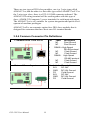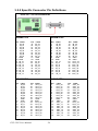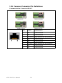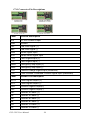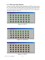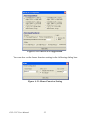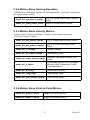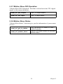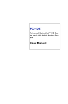
1
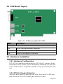
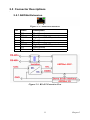
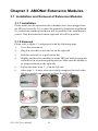
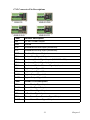
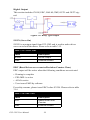
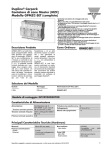
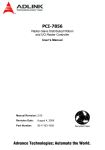
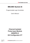
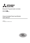
PCI-1202
2-Port AMONet™ RS-485 Master
Card
User Manual
Copyright
The documentation and the software included with this product are copyrighted 2004 by Advantech Co., Ltd. All rights are reserved. Advantech
Co., Ltd. reserves the right to make improvements in the products
described in this manual at any time without notice. No part of this manual may be reproduced, copied, translated or transmitted in any form or
by any means without the prior written permission of Advantech Co., Ltd.
Information provided in this manual is intended to be accurate and reliable. However, Advantech Co., Ltd. assumes no responsibility for its use,
nor for any infringements of the rights of third parties, which may result
from its use.
Acknowledgements
AMONet and PCI-1202 are trademarks of Advantech Inc.
Intel and Pentium are trademarks of Intel Corporation.
Microsoft Windows and MS-DOS are registered trademarks of
Microsoft Corp.
All other product names or trademarks are properties of their respective
owners.
Part No. 2003120200
1st Edition
Printed in Taiwan
May 2005
PCI-1202 User Manual
ii
Product Warranty (2 years)
Advantech warrants to you, the original purchaser, that each of its products will be free from defects in materials and workmanship for two years
from the date of purchase.
This warranty does not apply to any products which have been repaired or
altered by persons other than repair personnel authorized by Advantech,
or which have been subject to misuse, abuse, accident or improper installation. Advantech assumes no liability under the terms of this warranty as
a consequence of such events.
Because of Advantech’s high quality-control standards and rigorous testing, most of our customers never need to use our repair service. If an
Advantech product is defective, it will be repaired or replaced at no
charge during the warranty period. For out-of-warranty repairs, you will
be billed according to the cost of replacement materials, service time and
freight. Please consult your dealer for more details.
If you think you have a defective product, follow these steps:
1.
Collect all the information about the problem encountered. (For
example, CPU speed, Advantech products used, other hardware
and software used, etc.) Note anything abnormal and list any
onscreen messages you get when the problem occurs.
2.
Call your dealer and describe the problem. Please have your manual, product, and any helpful information readily available.
3.
If your product is diagnosed as defective, obtain an RMA (return
merchandize authorization) number from your dealer. This allows
us to process your return more quickly.
4.
Carefully pack the defective product, a fully-completed Repair and
Replacement Order Card and a photocopy proof of purchase date
(such as your sales receipt) in a shippable container. A product
returned without proof of the purchase date is not eligible for warranty service.
5.
Write the RMA number visibly on the outside of the package and
ship it prepaid to your dealer.
iii
CE
This product has passed the CE test for environmental specifications
when shielded cables are used for external wiring. We recommend the use
of shielded cables. This kind of cable is available from Advantech. Please
contact your local supplier for ordering information.
Technical Support and Assistance
Step 1. Visit the Advantech web site at www.advantech.com/support
where you can find the latest information about the product.
Step 2. Contact your distributor, sales representative, or Advantech's customer service center for technical support if you need additional
assistance. Please have the following information ready before
you call:
- Product name and serial number
- Description of your peripheral attachments
- Description of your software (operating system, version, application software, etc.)
- A complete description of the problem
- The exact wording of any error messages
Packing List
Before setting up the system, check that the items listed below are
included and in good condition. If any item does not accord with the
table, please contact your dealer immediately.
In addition to this User Manual, the package should also include the following items:
1.
PCI-1202: 2-Port AMONet RS-485 Master Card
2.
Advantech Driver Disc
PCI-1202 User Manual
iv
Contents
Chapter
1 Introduction ..................................................... 2
1.1
Card Description ............................................................... 2
1.2
1.3
1.4
Features ............................................................................. 3
Specifications .................................................................... 4
Supported Software ........................................................... 4
1.5
Chapter
Figure 1.1:Functional Block Diagram of PCI-1202 ...... 2
Figure 1.2:PCI-1202 Applications ................................. 3
1.4.1
1.4.2
Application Development ................................................. 5
Figure 1.3:Application Development ............................ 5
Figure 1.4:Flow Chart for Building an Application ...... 6
2 Installation ....................................................... 8
2.1
2.2
Check What You Have...................................................... 8
PCB Board Layout ............................................................ 9
2.3
Hardware Installation ........................................................ 9
2.4
2.5
Figure 2.1:PCB Layout of the PCI-1202 ....................... 9
2.3.1
2.3.2
2.3.3
2.3.4
Hardware Configuration ................................................ 9
PCI-Slot Socket Selection .............................................. 9
Installation Procedure .................................................. 10
Troubleshooting ........................................................... 10
Driver Installation ........................................................... 10
Connector Descriptions ................................................... 11
2.5.1
2.5.2
2.5.3
Chapter
Programming Library .................................................... 4
EzLINK .......................................................................... 4
AMONet Extension ..................................................... 11
Figure 2.2:AMONet Extension .................................... 11
Figure 2.3:RS-485 Extension Port ............................... 11
Digital I/O Connector(CN5) ........................................ 12
Figure 2.4:Digital I/O Connector ................................. 12
Figure 2.5:Digital Input Circuit ................................... 13
Figure 2.6:Digital Output Circuit ................................. 13
AMONet Extension Interface ...................................... 13
Figure 2.7:AMONet Slave Module Address Setting ... 13
3 AMONet Extension Modules ....................... 16
3.1
Installation and Removal of Extension Modules ............ 16
3.2
DIO Slave Modules......................................................... 17
3.1.1
3.1.2
3.2.1
3.2.2
3.2.3
Installation ................................................................... 16
Removal ....................................................................... 16
Figure 3.1:Inst. and Removal of Extension Modules .. 16
Features ........................................................................ 17
Specifications ............................................................... 17
Products Introduction ................................................... 17
Figure 3.2:ADAM-375XX Products & ADAM-3936 . 17
v
3.2.4
3.2.5
3.2.6
3.2.7
3.3
Motion Slave Modules .................................................... 23
3.3.1
3.3.2
3.3.3
3.3.4
3.3.5
3.3.6
Chapter
Common Connector Pin Definitions ............................ 18
Specific Connector Pin Definitions ............................. 20
Digital Input Signal Connection .................................. 22
Figure 3.3:NPN Sinking Type Input ............................ 22
Table 3.1:DI Pins ......................................................... 22
Digital Output Signal Connection ................................ 23
Figure 3.4:Relay Type Output ..................................... 23
Table 3.2:OUT1&OUT2 Pins ...................................... 23
Features ........................................................................ 23
Specifications ............................................................... 24
Product Introductions ................................................... 24
Figure 3.5:ADAM-32xx Products Series ..................... 24
Common Connector Pin Definitions ............................ 26
1-to-1 Cable Information ............................................. 32
Motion Signal Connection ........................................... 33
Figure 3.6:NPN Sinking Type Input ............................ 33
Table 3.3:STA Pins ...................................................... 33
Table 3.4:STP Pins ...................................................... 33
Table 3.5:PEL and MEL Pins ...................................... 34
Table 3.6:ORG Pins ..................................................... 34
Table 3.7:SLD Pins ...................................................... 35
Table 3.8:Table 3.8: ALM Pins ................................... 35
Table 3.9:INP Pins ....................................................... 35
Table 3.10:RDY Pins ................................................... 35
Table 3.11:DI Pins ....................................................... 36
Figure 3.7:PNP/NPN Sinking Type Input ................... 36
Table 3.12:LTC Pins .................................................... 37
Table 3.13:EMG Pins .................................................. 37
Table 3.14:BRK+/BRK- Pins ...................................... 37
Figure 3.8:Relay Type Output ..................................... 38
Table 3.15:SVON Pins ................................................ 38
Table 3.16:ERC Pins .................................................... 38
Table 3.17:RALM Pins ................................................ 39
Table 3.18:CMP Pins ................................................... 39
Table 3.19:OUT1&OUT2 Pins .................................... 39
Table 3.20:BSY Pins .................................................... 39
Figure 3.9:DDA Pulse Output ..................................... 40
Table 3.21:DDA Pulse Pins ......................................... 40
Figure 3.10:Encoder Feedback Input Signal ................ 40
Table 3.22:Encoder Pins .............................................. 41
4 Utility Software.............................................. 44
4.1
EzLink ............................................................................. 44
4.1.1
4.1.2
4.1.3
PCI-1202 User Manual
Minimum System Requirements ................................. 44
Description ................................................................... 44
Figure 4.1: Start-up of EzLink ..................................... 45
Scan Master Cards ....................................................... 45
Figure 4.2:Scan Master Cards ...................................... 45
Figure 4.3:Scanning Master ........................................ 46
vi
4.1.4
4.1.5
4.1.6
4.1.7
4.1.8
Chapter
Figure 4.4:Scan is Completed ...................................... 46
Figure 4.5:Scan Results .............................................. 46
Remote Slave Module .................................................. 47
Figure 4.6:Remote Slave Module ................................ 47
Figure 4.7:Status for the Slave Connection ................. 47
Scan Remote Slave Modules ....................................... 48
Figure 4.8:Scan Slave Modules ................................... 48
Figure 4.9:Scan Error ................................................... 48
Figure 4.10:Successful Scan Result ............................ 48
Slave Module Status Display ....................................... 49
Figure 4.11:Scan Results ............................................. 49
Figure 4.12:Message about the slave module .............. 49
DIO Type Slave Module .............................................. 50
Figure 4.13:DI 32 ......................................................... 50
Figure 4.14:DI16DO16 ................................................ 50
Figure 4.15:DO 32 ....................................................... 50
1-axis Motion Slave ..................................................... 51
Figure 4.16:Operation of 1-axis Motion Slave ............ 51
Figure 4.17:Configuration of 1-Axis Motion Slave ..... 51
Figure 4.18:Pulse I/O Configuration ........................... 52
Figure 4.19:Home Function Setting ............................. 52
5 AMONet API ................................................. 54
5.1
5.2
5.3
Data Definitions .............................................................. 54
AMONet Master Control API ......................................... 55
5.2.1
5.2.2
5.2.3
Hardware Installation ................................................... 55
Local I/O Operation ..................................................... 55
Ring Operation ............................................................. 55
Motion Slave ................................................................... 56
5.3.1
5.3.2
5.3.3
5.3.4
5.3.5
5.3.6
5.3.7
5.3.8
System Installation ....................................................... 56
Motion Slave Homing Operation ................................. 57
Motion Slave Velocity Motion .................................... 57
Motion Slave Point-to-Point Motion ........................... 57
Motion Slave Position Control and Counter ................ 58
Motion Slave Position Compare and Latch ................. 58
Motion Slave DIO Operation ....................................... 59
Motion Slave Status ..................................................... 59
vii
PCI-1202 User Manual
viii
CHAPTER
1
2
Introduction
This chapter gives an overview of the
product features, applications, and
specifications for PCI-1202
Sections include:
• Card Description
• Features
• Specifications
• Supported Software
• Application Development
Chapter 1 Introduction
The Advantech PCI-1202 motion controller is designed for users who
need to develop powerful applications quickly and easily. PCI-1202 is a
standard PCI-Bus motion controller with a high-speed real-time network
extension called AMONet. Advantech optimizes the software to help you
get your advanced motion profiles as quickly as possible.
AMONet is a new series of products designed for versatile automation
applications especially with distributed motion control requirements.
PCI-1202 is equipped with 2 master rings, and each master ring can connect with up to 64 slave modules. There are 2 categories of slave modules; one is for 1-axis motion control; the second is for digital I/O with 4
types, 32-IN, 32-OUT, 16-IN & 16-0UT and 24-IN & 8-OUT.
1.1 Card Description
The PCI-1202 is a Standard AMONet PCI-Bus Interface Master Card.
Figure 1.1: Functional Block Diagram of PCI-1202
PCI-1202 User Manual
2
Figure 1.2: PCI-1202 Applications
1.2 Features
• 2 Rings of AMONet master
• Programmable baud-rate up to 20 Mbps transfer rate
• Max. 128 AMONet digital slave modules support
• Easy installation with RJ45 phone jack and LED diagnostic
3
Chapter 1
1.3 Specifications
• Number of Rings: 2
• Transmission Speeds: 2.5, 5, 10, 20 Mbps with automatic data flow
control
• Serial Interface: half duplex RS-485 with transformer isolation
• Cable Type: CAT5 UTP/STP Ethernet cable
• Surge Protection: 10 kV
• Communication Distance: Max. 100 m (20 Mbps/32 slave modules)
• Communication Slave Module Capacity: 2 Rings with Max. 128 (1
ring has 64 slaves)
• Digital Input: 8-Ch isolated, sink type, 0-24 V DC, Max. 50 mA current , 10 mA sink current
• Digital Output: 4-Ch isolated, open collector type, 5~30 V DC voltage
Max. 10 mA sink current (open collector)
• PCI Specification: 2.2, supports 32-bit, 3.3 or 5 V DC operation
• Power Consumption: +5 V DC at 0.5 A typical
• Working Temperature: 0 to 60° C
1.4 Supported Software
1.4.1 Programming Library
For customers who are writing their own programs, we provide BCB++/
VB/VC++ programming libraries and Windows 2000/XP DLL for PCI1202. These function libraries are shipped with the board. There is also
support for Windows 2000/XP, and Embedded XP.
1.4.2 EzLINK
EzLINK is a utility software tool for AMONet. It is usually used offline
to test and debug the communication status, I/O slave module operation
and motion slave operation.
PCI-1202 User Manual
4
1.5 Application Development
Figure 1.3: Application Development
5
Chapter 1
Fig. 1-4 is a flow chart that illustrates the recommended process in using
this manual to develop an application. Refer to the related chapters for
details of each step.
Figure 1.4: Flow Chart for Building an Application
PCI-1202 User Manual
6
CHAPTER
2
2
Installation
This chapter describes how to install
PCI-1202.
Sections include:
• Check What You Have
• PCB Board Layout
• Hardware Installation
• Driver Installation
• Connector Descriptions
Chapter 2 Installation
This chapter describes how to install the PCI-1202. Please follow these
steps below to install the PCI-1202.
• Check what you have (section 2.1)
• Check PCB Board (section 2.2)
• Install hardware (section 2.3)
• Install software driver (section 2.4)
Understanding the I/O signal connections and their operation (chapter
3,4)
Understanding the connectors’ pin assignments (the rest of the sections)
and wiring the connections
2.1 Check What You Have
In addition to this User Manual, the package should also include the following items:
• PCI-1202: 2-Port AMONet RS-485 Master Card
• Advantech Driver Disc
• An optional terminal board for wiring purposes. (If a different model is
ordered.)
If any of these items are missing or damaged, contact the dealer from
whom you purchased the product. Save the shipping materials and carton
in case you want to ship or store the product in the future.
PCI-1202 User Manual
8
2.2 PCB Board Layout
Figure 2.1: PCB Layout of the PCI-1202
Name
Description
PCI-1202
CN1
RJ-45, AMONet extension connector
CN2
RJ-45, AMONet extension connector
CN5
DSUB 15-pin digital I/O connector
2.3 Hardware Installation
2.3.1 Hardware Configuration
PCI-1202 is a standard extension device of PCI for PC systems. All the
functions in a base system, such as the memory allocation, I/O port locations, and the address assignment, should be setup by following the manual.
2.3.2 PCI-Slot Socket Selection
Most PCs have both PCI and ISA slots. Don’t force the PCI-1202 card
into an ISA slot. PCI-1202 can be only used in PCI slots.
9
Chapter 2
2.3.3 Installation Procedure
1.
Please read this manual first, and then setup the jumper and switch
of the product in accordance to your needs.
2.
Turn off your PC’s power, and make sure the AC power is disconnected. Also turn off the power on all accessories (printer, modem,
monitor, etc.) connected to the computer.
3.
Open the chassis cover of the PC, and install the card. PCI-1202
can only be installed in a standard 32-bit PCI extension slot. It can’t
be used in a standard ISA or other extension slot.
4.
Before handling PCI-1202, discharge any static buildup on your
body which may damage the product.
5.
Position PCI-1202 in the correct PCI slot, and fix it. Secure the card
in place at the front PCB panel of the system unit by using screws
removed from the socket.
6.
When removing the product, be sure to cut off the power first. Then
take PCI-1202 out of the system board.
2.3.4 Troubleshooting
If your system doesn’t boot correctly, please turn it off and make sure the
AC power is disconnected. Open the chassis cover of the PC and confirm
that PCI-1202 is firmly attached in its socket, that screws are locked and
PCI-1202 is set with correct jumper and switch configuration.
Please make sure the PC system is working correctly when PCI-1202 is
removed. If the PC system is working correctly after removing PCI-1202,
please follow standard installation steps to reinstall PCI-1202. If the system still can’t boot correctly after the reinstallation of PCI-1202, please
contact your supplier for support.
2.4 Driver Installation
Auto-Run from the Advantech Driver CD. Choose Driver Installation ->
PCI-1202.
Follow the procedures of the installer.
After setup installation is completed, restart Windows.
PCI-1202 User Manual
10
2.5 Connector Descriptions
2.5.1 AMONet Extension
Figure 2.2: AMONet Extension
Pin
Label
Description
1
2
3
4
5
6
7
8
FG
FG
RS485+
FG
FG
RS485FG
FG
Filed Ground
Filed Ground
High Speed RS-485 protocol
Filed Ground
Filed Ground
High Speed RS-485 protocol
Filed Ground
Filed Ground
Figure 2.3: RS-485 Extension Port
11
Chapter 2
2.5.2 Digital I/O Connector(CN5)
Figure 2.4: Digital I/O Connector
Pin
Label
Description
1
INPUT1
Digital Input #1
2
INPUT2
Digital Input #2
3
INPUT3
Digital Input #3
4
INPUT4
Digital Input #4
5
GND
Power Ground
6
INPUT5
Digital Input #5
7
INPUT6
Digital Input #6
8
INPUT7
Digital Input #7
9
INPUT8
Digital Input #8
10
N.C.
Reserved
11
OUTPUT1
Digital Output #1
12
OUTPUT2
Digital Output #2
13
OUTPUT3
Digital Output #3
14
OUTPUT4
Digital Output #4
15
GND
Power Ground
PCI-1202 User Manual
12
Figure 2.5: Digital Input Circuit
Figure 2.6: Digital Output Circuit
2.5.3 AMONet Extension Interface
Figure 2.7: AMONet Slave Module Address Setting
13
Chapter 2
PCI-1202 User Manual
14
CHAPTER
3
2
AMONet Extension
Modules
Sections include:
• Installation and Removal of Extension Modules
• DIO Slave Module
• Motion Slave Modules
Chapter 3 AMONet Extension Modules
3.1 Installation and Removal of Extension Modules
3.1.1 Installation
Please make sure the extension (slave) modules have been plugged into
the DIN rail correctly. Try to move the module by hand after installation.
No vertical movement up and down will be possible if the installation is
correct. Only horizontal movement right and left will be possible.
3.1.2 Removal
Please refer to figure 3.1 and proceed with the following steps.
1.
Use a flat screwdriver
2.
Plug this screwdriver into the bar on the right end
3.
Push the screwdriver to pull out the bar
4.
Slightly pull the slave module out of the DIN rail while keeping the
screwdriver in its position pulling the bar. Make sure the module is
no longer attached on the right side.
5.
Follow the same steps 2 ~ 4 on the left side.
6.
After steps 1 ~ 4 have been successfully completed for both sides,
the slave module can be removed from the DIN rail.
Figure 3.1: Installation and Removal of Extension Modules
PCI-1202 User Manual
16
3.2 DIO Slave Modules
3.2.1 Features
• DIN rail mounting (LxWxH): 124 x 72 x 53 mm
• Max. 20 Mbps transfer rate
• 3-Wire terminal board for actuator/sensor
• Easy installation with RJ45 phone jack and LED diagnostic
• Serial interface: half duplex RS-485 with transformer isolation
3.2.2 Specifications
• Cable Type: CAT5 UTP/STP Ethernet cable
• Surge Protection: 10 kV
• Transmission Speed: 2.5, 5, 10 and 20 Mbps
• On-line module insertion and removal
• I/O Isolation Voltage: 2.5 kVrms
• Input Impedance: 2.4 k/0.5 Ω, Input current: ±10 mA (Max)
• Output Types: NPN/PNP open collector Darlington transistors
• Switch Capacity: each output channel is 60 mA at 24 V DC
• Response Time: On to Off, about 180 µs; Off to On, about 1.2 µs
• Power Supply: +18 V DC to +30 V DC, consumption: 3 W typical
• Operating Temperature: 0 ~ 60° C
3.2.3 Products Introduction
Figure 3.2: ADAM-375XX Products Series and ADAM-3936
17
Chapter 3
There are two types of DIO slave modules, one is a 3-wire type called
ADAM-37xx, and the other is a flat-cable type called ADAM-37xxF. For
the 3-wire type slave, there is a PCL-10136M connector onboard. The
ADAM-3936 wiring terminal will be used together with this type of
slave. ADAM-3936 supports 3 screw terminals for each input and output.
The ADAM-37xx is very suitable for system integration and quick development of machine prototypes.
ADAM-37xxF is an economic option for a DIO slave modules that is
designed for customers that have their own I/O terminal boards.
3.2.4 Common Connector Pin Definitions
Communication Conn. RJ-45
Pin
1
2
3
4
5
6
7
8
External Power Input connector
PCI-1202 User Manual
18
Pin
1
2
3
4
5
6
Label Description
NC
Filed Ground
NC
Filed Ground
RS485+ High Speed
RS-485 protocol
NC
Filed Ground
NC
Filed Ground
RS485- High Speed
RS-485 protocol
NC
Filed Ground
NC
Filed Ground
Label
24V
GND
FG
24V
GND
FG
Description
DC 24V
DC 24V Ground
Field Ground
DC 24V
DC 24V Ground
Field Ground
ID Setting DIP Switch
Pin
1
2
3
4
5
6
Label
A5
A4
A3
A2
A1
A0
ON
1
1
1
1
1
1
OFF
0
0
0
0
0
0
Note: Node Number=
32xA5+16xA4+8xA3+4xA2+2xA1
+A0
Configuration Settings
PinLabel Description
1
2
3
4
5
6
B1
B0
TD
TM
BK
TR
ON OFF
*Baud-Rate Setting
1 0
*Baud-Rate Setting
1 0
Time-out Status Latch
Watchdog Mode
Reserved
Terminate Resistance
Enable Disable
How to use Baud-Rate Setting
B0
OFF
OFF
ON
ON
B1
Baud-Rate Setting
OFF 1/4 System Clock
ON 1/8 System Clock
OFF 1/16 System Clock
ON 1/32 System Clock
Note:
default system clock = 80 Mhz
19
Chapter 3
3.2.5 Specific Connector Pin Definitions
ADAM-375x Pin Definitions
ADAM-3752
Pin
1
2
3
4
5
6
7
8
9
10
11
12
13
14
15
16
17
18
Label
IN_00
IN_01
IN_02
IN_03
IN_04
IN_05
IN_06
IN_07
GND
GND
IN_10
IN_11
IN_12
IN_13
IN_14
IN_15
IN_16
IN_17
ADAM-3758
Pin
19
20
21
22
23
24
25
26
27
28
29
30
31
32
33
34
35
36
Label
IN_20
IN_21
IN_22
IN_23
IN_24
IN_25
IN_26
IN_27
GND
GND
IN_30
IN_31
IN_32
IN_33
IN_34
IN_35
IN_36
IN_37
Pin
1
2
3
4
5
6
7
8
9
10
11
12
13
14
15
16
17
18
ADAM-3756
Pin
1
2
3
4
5
6
7
8
9
10
11
12
13
14
15
16
17
18
Label
IN_00
IN_01
IN_02
IN_03
IN_04
IN_05
IN_06
IN_07
GND
GND
IN_10
IN_11
IN_12
IN_13
IN_14
IN_15
IN_16
IN_17
Label
IN_00
IN_01
IN_02
IN_03
IN_04
IN_05
IN_06
IN_07
GND
GND
IN_10
IN_11
IN_12
IN_13
IN_14
IN_15
IN_16
IN_17
Pin
19
20
21
22
23
24
25
26
27
28
29
30
31
32
33
34
35
36
Label
IN_20
IN_21
IN_22
IN_23
IN_24
IN_25
IN_26
IN_27
GND
GND
OUT_30
OUT_31
OUT_32
OUT_33
OUT_34
OUT_35
OUT_36
OUT_37
Pin
19
20
21
22
23
24
25
26
27
28
29
30
31
32
33
34
35
36
Label
OUT_20
OUT_21
OUT_22
OUT_23
OUT_24
OUT_25
OUT_26
OUT_27
GND
GND
OUT_30
OUT_31
OUT_32
OUT_33
OUT_34
OUT_35
OUT_36
OUT_37
ADAM-3754
Pin Label
19
OUT_20
20
OUT_21
21
OUT_22
22
OUT_23
23
OUT_24
24
OUT_25
25
OUT_26
26
OUT_27
27
GND
28 GND
29
OUT_30
30
OUT_31
31
OUT_32
32
OUT_33
33
OUT_34
34
OUT_35
35
OUT_36
36
OUT_37
PCI-1202 User Manual
Pin
1
2
3
4
5
6
7
8
9
10
11
12
13
14
15
16
17
18
20
Label
OUT_00
OUT_01
OUT_02
OUT_03
OUT_04
OUT_05
OUT_06
OUT_07
GND
GND
OUT_10
OUT_11
OUT_12
OUT_13
OUT_14
OUT_15
OUT_16
OUT_17
ADAM-375xF Pin Definitions
ADAM-3754F
ADAM-3754F
CN1
Pin
1
3
5
7
9
11
13
15
17
19
21
23
25
27
29
31
33
CN2
Label
OUT_00
OUT_01
OUT_02
OUT_03
OUT_04
OUT_05
OUT_06
OUT_07
OUT_10
OUT_11
OUT_12
OUT_13
OUT_14
OUT_15
OUT_16
OUT_17
FG
Pin
2
4
6
8
10
12
14
16
18
20
22
24
26
28
30
32
34
Label
+24V
GND
+24V
GND
+24V
GND
+24V
GND
+24V
GND
+24V
GND
+24V
GND
+24V
GND
FG
ADAM-3752F
Label
OUT_20
OUT_21
OUT_22
OUT_23
OUT_24
OUT_25
OUT_26
OUT_27
OUT_30
OUT_31
OUT_32
OUT_33
OUT_34
OUT_35
OUT_36
OUT_37
FG
Pin
2
4
6
8
10
12
14
16
18
20
22
24
26
28
30
32
34
Label
+24V
GND
+24V
GND
+24V
GND
+24V
GND
+24V
GND
+24V
GND
+24V
GND
+24V
GND
FG
Pin
2
4
6
8
10
12
14
16
18
20
22
24
26
28
30
32
34
Label
+24V
GND
+24V
GND
+24V
GND
+24V
GND
+24V
GND
+24V
GND
+24V
GND
+24V
GND
FG
ADAM-3752F
CN1
Pin
1
3
5
7
9
11
13
15
17
19
21
23
25
27
29
31
33
Pin
1
3
5
7
9
11
13
15
17
19
21
23
25
27
29
31
33
CN2
Label
IN_00
IN_01
IN_02
IN_03
IN_04
IN_05
IN_06
IN_07
IN_10
IN_11
IN_12
IN_13
IN_14
IN_15
IN_16
IN_17
FG
Pin
2
4
6
8
10
12
14
16
18
20
22
24
26
28
30
32
34
Label
+24V
GND
+24V
GND
+24V
GND
+24V
GND
+24V
GND
+24V
GND
+24V
GND
+24V
GND
FG
Pin
1
3
5
7
9
11
13
15
17
19
21
23
25
27
29
31
33
21
Label
IN_20
IN_21
IN_22
IN_23
IN_24
IN_25
IN_26
IN_27
IN_30
IN_31
IN_32
IN_33
IN_34
IN_35
IN_36
IN_37
FG
Chapter 3
ADAM-3756F
ADAM-3756F
CN1
Pin
1
3
5
7
9
11
13
15
17
19
21
23
25
27
29
31
33
CN2
Label
IN_00
IN_01
IN_02
IN_03
IN_04
IN_05
IN_06
IN_07
IN_10
IN_11
IN_12
IN_13
IN_14
IN_15
IN_16
IN_17
FG
Pin
2
4
6
8
10
12
14
16
18
20
22
24
26
28
30
32
34
Label
+24V
GND
+24V
GND
+24V
GND
+24V
GND
+24V
GND
+24V
GND
+24V
GND
+24V
GND
FG
Pin
1
3
5
7
9
11
13
15
17
19
21
23
25
27
29
31
33
Label
OUT_00
OUT_01
OUT_02
OUT_03
OUT_04
OUT_05
OUT_06
OUT_07
OUT_10
OUT_11
OUT_12
OUT_13
OUT_14
OUT_15
OUT_16
OUT_17
FG
Pin
2
4
6
8
10
12
14
16
18
20
22
24
26
28
30
32
34
3.2.6 Digital Input Signal Connection
Figure 3.3: NPN Sinking Type Input
IN1 & IN2 (Digital Input)
Digital input for each axis is shown in table 3.1.
Table 3.1: DI Pins
Label
Description
GND
External Ground
DI
General DI
PCI-1202 User Manual
22
Label
+24V
GND
+24V
GND
+24V
GND
+24V
GND
+24V
GND
+24V
GND
+24V
GND
+24V
GND
FG
3.2.7 Digital Output Signal Connection
Figure 3.4: Relay Type Output
OUT1 & OUT2 (Digital Output)
Digital output for each axis is designed for general-purpose output function. Please refer to the following table 3.2.
Table 3.2: OUT1&OUT2 Pins
Label
Description
GND
External Ground
DO
Digital Outputs
3.3 Motion Slave Modules
3.3.1 Features
• DIN rail mounting L x W x H: 124 x 72 x 53 mm)
• Max. 20 Mbps transfer rate
• Max. 6.5 MHz, 1-Axis pulse output
• 28-bit counter for incremental encoder
• Programmable acceleration and deceleration time
• T-curve and S-curve velocity profiles support
• Change speed on-the-fly
• Simultaneously start/stop on multiple motion control modules
(reserved)
• Easy installation with RJ45 phone jack and LED diagnostic
• Easy installation for servo or stepping motor driver
23
Chapter 3
3.3.2 Specifications
Series interface: Half duplex RS-485 with transformer isolation
Cable type: CAT5 UTP/STP Ethernet cable
Surge protection: 10 kV
Transmission speed: 2.5, 5, 10 and 20 Mbps
Programmable Pulse output mode: ±OUT/DIR, ±CW/CCW, ±A/B phase
Programmable pulse command speed: Max 6.5Mpps / Min 0.05pps
Position range: 28 bits (±134,217,728 pulses)
Home return mode: 13 types
Velocity profiles: T-curve, S-curve
Counter for encoder feedback signals: 28 bits up/down
Position latch input: LTC
Position compare output: CMP
Incremental encoder input: ±EA, ±EB
Encoder index signal input: ±EZ
Machine interface: PEL, MEL, ORG, SLD
Servo driver interface: ALM, RDY, SVON, INP, ERC
Simultaneous start/stop motion input: STA, STP (Reserved)
LED indicator: PWR, RUN, ERR, PEL, MEL, ORG, SLD
Power supply: +18V DC to +30V DC, consumption: 3W typical
Operating temperature: 0 to 60° C
3.3.3 Product Introductions
Figure 3.5: ADAM-32xx Products Series
PCI-1202 User Manual
24
Unlike traditional motion card solutions, AMONet supports remote
motion slave modules for extended multiple-axis applications. All these
extended motion slave modules are connected serially by a simple CAT5
cable with RJ45 connectors. This reduces wiring between the motion
driver and controller and provides a motion control system that is very
suitable for highly integrated machine automation applications.
AMONet supports driver-specific motion slave modules such as the
motion slave module for Mitsubishi J2-Super series Driver/Motor, and
Panasonic Minas A type servo driver/motor.
Please select the matching cable PCL-10120M or PCL-10150M and plug
this cable into both the motion driver and motion slave module. AMONet
also supports general purpose motion slave modules for general driver/
motors including step driver/motors. This general-purpose motion slave
module is designed with many screw terminals onboard to support easy
wiring. Please refer to the relevant installation guides.
25
Chapter 3
3.3.4 Common Connector Pin Definitions
Communication Connector RJ-45
PCI-1202 User Manual
Pin
Label
Description
1
NC
Filed Ground
2
NC
Filed Ground
3
RS-485+
High Speed RS-485 protocol
4
NC
Filed Ground
5
NC
Filed Ground
6
RS-485-
High Speed RS-485 protocol
7
NC
Filed Ground
8
NC
Filed Ground
26
External Power Input Connector
Pin
Label
Description
1
24V
DC 24V
2
GND
DC 24V Ground
3
FG
Field Ground
4
24V
DC 24V
5
GND
DC 24V Ground
6
FG
Field Ground
27
Chapter 3
Slave ID Setting DIP Switch
Pin
Label
ON
OFF
1
A5
1
0
2
A4
1
0
3
A3
1
0
4
A2
1
0
5
A1
1
0
6
A0
1
0
Note: Node Number=32xA5+16xA4+8xA3+4xA2+2xA1+A0
PCI-1202 User Manual
28
Configuration Setting
Switch
Label
Description
ON
OFF
1
B1
1
0
2
B0
Baud-Rate
Setting
1
0
3
TD
Time-Out Status Latch
Enable
Disable
4
TM
Watchdog
Mode
Enable
Enable
5
*BK
*Break and
Rescan Communication
Enable
Disable
6
TR
Terminate
Resistance
Enable
Disable
*BK function is reserved.
How to Use the Baud-Rate Setting
B0
B1
Baud-Rate Setting
OFF
OFF
1/4 System Clock
OFF
ON
1/8 System Clock
ON
OFF
1/16 System Clock
ON
ON
1/32 System Clock
Note: default system clock = 80 MHz
29
Chapter 3
CN1 Connector Pin Descriptions
Label
General Description
24V
DC 24V Power Output
GND
Ground
PEL
End Limit Signal (+)
MEL
End Limit Signal (-)
ORG
Home Signal Input
SLD
Ramp-Down Signal Input
LTC+
Latch Signal Input (+)
LTC-
Latch Signal Input (-)
EMG+
Emergency Stop Input (+)
EMG-
Emergency Stop Input (-)
PCS
Position Change Signal Input (Reserved)
CLR
Clear Position Command Counter Signal Input (Reserved)
Label
ADAM-3210 Description
OUT+
Pulse Signal Output (+)
OUT-
Pulse Signal Output (-)
DIR+
Direction Signal Output(+)
DIR-
Direction Signal Output(-)
EA+
Encoder A Phase (+)
EA-
Encoder A Phase (-)
EB+
Encoder B Phase (+)
EB-
Encoder B Phase (-)
EZ+
Encoder Z Phase (+)
EZ-
Encoder Z Phase (-)
PCI-1202 User Manual
30
CN2 Connector Pin Descriptions
Label
General Description
24V
DC 24V Power Output
GND
Ground
STA
Simultaneous Start Input (Reserved)
STP
Simultaneous Stop Input (Reserved)
CMP
Position Compare Output
BSY
Motion Busy Signal Output
BRK
Machinery Break Signal Input (106-M131-J2S)
BRK+
Machinery Break Signal (+) Input
BRK-
Mechanical Brake Release Signal (-) Input
IN1
Digital Input Signal #1
IN2
Digital Input Signal #2
OUT1
Digital Output Signal #1
OUT2
Digital Output Signal #2
Label
ADAM-3210 Description
RDY
Servo Ready Signal input
SVON
Servo On Signal Output
ALM
Servo Alarm Signal Input
INP
In-Position Signal Input
ERC
Clear Servo Error Counter Signal Output
ALMC
Servo Alarm Clear Signal Output
31
Chapter 3
3.3.5 1-to-1 Cable Information
ADAM-3211/PMA
ADAM-3212/J2S
ADAM-3213/YS2
PCI-1202 User Manual
32
3.3.6 Motion Signal Connection
Digital Input (1)
This section includes STA, STP, PCS, CLR, PEL, MEL, ORG, SLD,
ALM, INP, RDY, IN1 and IN2 signal:
Figure 3.6: NPN Sinking Type Input
STA (Simultaneous Start)
STA is used to start all the motors connected to the same ring simultaneously. Please refer to table 3.3 for detailed information.
Table 3.3: STA Pins
Label
Description
STA
Simultaneous Start Signal
GND
External Ground
STP (Simultaneous Stop)
STP is used to stop all the motors connected to the same ring simultaneously. Please refer to table 3.4 for detailed information.
Table 3.4: STP Pins
Label
Description
STP
Simultaneous Stop Signal
GND
External Ground
33
Chapter 3
PCS (Position Change)
This function is conserved for the further application, not supported by
the current dynamic link library (DLL) driver now.
CLR (Clear Position Command Counter)
This function is conserved for the further application, not supported by
the current dynamic link library (DLL) driver now.
PEL & MEL (Plus End Limit / Minus End Limit)
There are two end-limit signals called PEL and MEL. The default setting
is Normal-Close type signals from external sensors (Can be set by SW2).
PEL indicates the limit of motion in the plus direction and MEL indicates
the limit of motion in the minus direction. The relative signal names, pin
number are shown in the following table.
Table 3.5: PEL and MEL Pins
Label
Description
GND
External Ground
PEL
Plus End Limit
MEL
Minus End Limit
ORG (Origin)
The origin signal is necessary when the position feedback is of the incremental type or if no feedback encoders are used. The origin signals are
used to indicate the origin of the system. Please refer to table 3.6 for
detailed information.
Table 3.6: ORG Pins
Label
Description
GND
External Ground
ORG
ORG signal
PCI-1202 User Manual
34
SLD (Slow Done)
The SLD signals are used to help the axis decelerate to stop by hardware.
Please refer to table 3.7 for descriptions of the signal name, pin number.
Table 3.7: SLD Pins
Label
Description
GND
External Ground
SLD
SLD Signal
ALM (Servo Alarm)
ALM- input signal from ALM signal at servo driver. The servo driver
will issue ALM output when it is under abnormal operation or overload.
Please refer to table 3.8 for a description.
Table 3.8: Table 3.8: ALM Pins
Label
Description
GND
External Ground
ALM
Servo ALM input
INP (Servo In Position)
INP is an input signal at PCI-1202 and is used to read the INP status
inside servo driver. Please refer to table 3.9 for descriptions.
Table 3.9: INP Pins
Label
Description
GND
External Ground
INP
Servo In-Position Input
RDY (Driver Ready)
RDY is an input signal and is used to read the RDY signal at servo driver.
Please refer to table 3.10.
Table 3.10: RDY Pins
Label
Description
GND
External Ground
RDY
Servo RDY input
35
Chapter 3
IN1 & IN2 (Digital Input)
Digital input is shown in table 3.11.
Table 3.11: DI Pins
Label
Description
DI
General DI
GND
External Ground
Digital Input (2)
This section includes LTC+, LTC-, EMG+, EMG-, BRK+ and BRK- signal:
Figure 3.7: PNP/NPN Sinking Type Input
PCI-1202 User Manual
36
LTC+ & LTC- (Counter Latch)
LTC is used to latch the value in the counter when the LTC input is
active. Table.3.12 lists the signal name and pin number.
Table 3.12: LTC Pins
Label
Description
LTC+
LTC- Input
LTC-
LTC- Input
GND
External Ground
EMG+ & EMG- (Emergency Stop)
EMG is shown in table 3.13.
Table 3.13: EMG Pins
Label
Description
EMG+
Emergency Stop
EMG-
Emergency Stop
GND
External Ground
BRK+ (Machinery Break Signal) & BRK- (Machinery Break Release
Signal)
BRK+ and BRK- is used to control the motor break function. Table.3.14
lists the signal name, pin number and axis number.
Table 3.14: BRK+/BRK- Pins
Label
Description
BRK+
Machinery Break Signal
BRK-
Machinery Break Release Signal
GND
External Ground
37
Chapter 3
Digital Output
This section includes SVON, ERC, RALM, CMP, OUT1 and OUT2 signal:
Figure 3.8: Relay Type Output
SVON (Servo On)
SVON is an output signal from PCI-1202 and is used to make driver
servo-on to hold the motor. Please refer to table 3.15.
Table 3.15: SVON Pins
Label
Description
SVON
SVON Output
GND
External Ground
ERC (Reset Driver error counter/Deviation Counter Clear)
ERC output will be active when the following conditions are activated.
• Homing is complete
• PEL/MEL is active
• ALM is active
• User issues EMG by software
For safety reasons, please issue ERC before SVON. Please refer to table
3.16.
Table 3.16: ERC Pins
Label
Description
ERC
Reset Driver error
Counter
GND
External Ground
PCI-1202 User Manual
38
RALM (Reset Servo Alarm)
This RALM signal is designed to reset ALM status inside the servo driver
if the alarm status can be reset. Please refer to table 3.17 for a description.
Table 3.17: RALM Pins
Label
Description
GND
External Ground
RALM
ALM reset output
CMP (Position Compare)
CMP signals are used to make a comparison between target value and
actual value and generate a trigger signal output. Please refer to table 3.18
for the signal name and pin number.
Table 3.18: CMP Pins
Label
Description
CMP
CMP Output
GND
External ground
OUT1 & OUT2 (Digital Output)
Digital output is designed for general-purpose output function. Please
refer to the following table 3.19.
Table 3.19: OUT1&OUT2 Pins
Label
Description
DO
Digital Outputs
GND
External Ground
BSY (Motion Busy Signal Output)
BSY signals indicate the current status of the motors.
Table 3.20: BSY Pins
Label
Description
BSY
Motion busy signal output
GND
External Ground
39
Chapter 3
DDA Pulse Output
This section includes OUT and DIP signal:
OUT and DIR (Pulse Output Control)
There are six types of pulse output for PCI-1202. Specify the electrical
specification as differential or open collector. Then select DIR/OUT or
CW/CCW. Refer to table 3.21 for the pin definition of the DIR/OUT
pins. You can also refer to the dipswitch setting in chapter 2.
Figure 3.9: DDA Pulse Output
Table 3.21: DDA Pulse Pins
Label
Description
OUT+
OUT(+)
OUT-
OUT(-)
DIR+
DIR(+)
DIR-
DIR(-)
Encoder Feedback Signal
EA, EB, and EZ for differential line driver input. Please refer to table
3.22 for the encoder input signal descriptions.
Figure 3.10: Encoder Feedback Input Signal
PCI-1202 User Manual
40
Table 3.22: Encoder Pins
Label
Description
EA+
Encoder A(+)
EA-
Encoder A(-)
EB+
Encoder B(+)
EB-
Encoder B(-)
EZ+
Encoder Z(+)
EZ-
Encoder Z(_)
41
Chapter 3
PCI-1202 User Manual
42
CHAPTER
4
2
Utility Software
Sections include:
• EzLink
Chapter 4 Utility Software
4.1 EzLink
EzLink is a user-friendly utility for the purpose of testing and debugging
AMONet. EzLink supports two types of remote slaves: DIO slave modules, and 1-axis motion slave modules.
There are three main steps to make use of EzLink: First, you scan how
many master cards are installed in the system. Then you can connect the
master and slave devices. After that, you can scan how many slave modules are installed in each ring of the master. EzLink can identify the type
of slaves as being DIO or Motion slave automatically and can test their
functions.
EzLink is designed to assist in testing system configurations. This can
reduce the communication effort between software programming engineers and hardware engineers. You do not have to do any coding during
the system configuration testing with EzLink. It is a really helpful tool to
both hardware and software engineers.
4.1.1 Minimum System Requirements
PC: IBM PC Compatible with at least x586 CPU
Memory: 128 MB RAM
OS: Windows 2000/XP
4.1.2 Description
Start-up of EzLink
The menu shown in figure 4.1 will be displayed when you start-up
EzLink. The menu selection is on top of the display. In the middle is an
SDI operation menu. Multiple dialog boxes can be shown in this display.
On the top is the tool bar, which can be used to do basic operations. In the
left window is an overview of the master card and slave modules that are
currently connected. On the right is information about slave modules
including slave ID. At the bottom, messages about the system such as
communication status and detailed operation information are displayed.
PCI-1247 User Manual
44
Figure 4.1: Start-up of EzLink
4.1.3 Scan Master Cards
Click on the first button on the tool bar to scan master cards in the system.
All master cards will be identified after the scanning is completed as
shown in figure 4.2 to 4.5, and all master cards will be listed in the menu.
Figure 4.2: Scan Master Cards
45
Chapter 4
Figure 4.3: Scanning Master
Figure 4.4: Scan is Completed
Figure 4.5: Scan Results
PCI-1247 User Manual
46
4.1.4 Remote Slave Module
After completely scanning the master cards, you can connect the master
and remote slaves by clicking on the connect button on the tool bar as
shown in figure 4.6 and figure 4.7. Whether the slave is connected or not
connected with the master cards can be read from the bottom window that
shows system status.
Figure 4.6: Remote Slave Module
Figure 4.7: Status for the Slave Connection
47
Chapter 4
4.1.5 Scan Remote Slave Modules
After the connection between the master and slave has been set up successfully, you can scan the slave modules that are installed in this ring of
the master card. Both the number and types of slave modules will be displayed on the left. The slave modules can be either DIO slave or 1-axis
motion slave as shown in figure 4.8 to 4.10.
Figure 4.8: Scan Slave Modules
Figure 4.9: Scan Error
Figure 4.10: Successful Scan Result
PCI-1247 User Manual
48
4.1.6 Slave Module Status Display
All master cards and slave modules will be displayed on the left menu
after you have successfully scanned the master, connected the master and
slave, and scanned all slaves. Please refer to figure 4.11.
Figure 4.11: Scan Results
You can click on each individual slave module in the menu, the information about the selected slave module will be displayed on the right as
shown in figure 4.12. In this dialog box , the ID and Type of the slave
module will be displayed.
Figure 4.12: Message about the slave module
49
Chapter 4
4.1.7 DIO Type Slave Module
2 types of icons are applied in the operation box of DIO type slave module. The green lamp is for input signal, the red button is for output signal.
User can click on the red button and send output signals thereafter. User
can read the input status from the green lamp. Please refer to the following pictures Fig.4.13 ~Fig.4-15
Figure 4.13: DI 32
Figure 4.14: DI16DO16
Figure 4.15: DO 32
PCI-1247 User Manual
50
4.1.8 1-axis Motion Slave
There are 2 menus for the 1-axis motion slave modules. One is for operation , the other is for configuration as shown in the following figures
Fig.4.16 and Fig.4.17. Before proceeding to the operation menu , please
check the settings in the configuration menus first. Correct I/O configuration settings are necessary for successful operations.
Figure 4.16: Operation of 1-axis Motion Slave
Please check the following settings including ALM, ERC, INP, ORG,
LTC, SLD and especially the type of pulse output and encoder inputs.
Figure 4.17: Configuration of 1-Axis Motion Slave
51
Chapter 4
Figure 4.18: Pulse I/O Configuration
You can also set the home function setting in the following dialog box:
Figure 4.19: Home Function Setting
PCI-1247 User Manual
52
CHAPTER
5
2
AMONet API
Chapter 5 AMONet API
This chapter provides a brief introduction to the AMONet API. For more
detailed function descriptions and programming examples, please refer to
the Programming Guide in the CD.
CDROM\Manual\PCI-1202 Programming Guide.pdf
5.1 Data Definitions
Name
Description
Range
U8
8-bit ASCII character
0 to 255
I16
16-bit signed integer
-32768 to 32767
U16
16-bit unsigned integer
0 to 65535
I32
long integer
-2147483648 to 2147483647
U32
32-bit unsigned long integer
0 to 4294967295
F32
32-bit single-precision floating-point
-3.402823E38 to
3.402823E38
F64
64-bit double-precision
floating-point
-1.797683134862315E308 to
1.797683134862315E309
Boolean
logic value
TRUE, FALSE
PCI-1202 User Manual
54
5.2 AMONet Master Control API
This section describes the API of the PCI-1202 master card, including
hardware installation, local I/O operation, and ring operation.
5.2.1 Hardware Installation
“Hardware installation” functions initialize/terminate the PCI-1202
device on your system.
Function Name
Description
_1202_open
Initialize system resource
_1202_close
Release all resources
5.2.2 Local I/O Operation
“Local I/O Operation” functions help you read and write digital signals
through the local board port (CN5).
Function Name
Description
_1202_lio_read
Read input value from local 10
_1202_lio_write
Write output value to local 10
5.2.3 Ring Operation
“Ring Operation” functions initialize/terminate the onboard master rings
and enable/disable the functionality of the rings.
Function Name
Description
_mnet_start_ring
Start ring communication
_mnet_stop_ring
Stop ring communication
_mnet_reset_ring
Soft reset ring and recorder data
_mnet_get_ring_active_table
Get the active slave table
_mnet_enable_soft_watchdog
Enable watch dog
_mnet_set_ring_quality_param
Set the ring communication quality
_mnet_get_slave_info
Get the slave information
_mnet_get_error_device
Get the first error slave device
55
Chapter 5
5.3 Motion Slave
This section describes the API of the distributed motion/DIO functions,
include system installation, homing operation, velocity motion, point-topoint motion, position control and counter, position compare and latch,
DIO function and slave module status readback.
5.3.1 System Installation
Function Name
Description
_mnet_m1_initial
Initial The Remote Axis Resource
_mnet_m1_set_pls_iptmode
Set Encoder Input Mode
_mnet_m1_set_pls_outmode
Set Pulse Command Output Mode
_mnet_m1_set_feedback_src
Set The Counters Input Source
_mnet_m1_set_alm
Set Alarm Logic And Operating Mode
_mnet_m1_set_inp
Set INP Logic And Operating Mode
_mnet_m1_set_erc
Set ERC Logic And Timing
_mnet_m1_set_erc_on
Fource ERC Output
_mnet_m1_set_sd
Set SD Logic And Operating Mode
_mnet_m1_set_svon
Set Servo Driver ON
_mnet_m1_set_ralm
Output Servo Driver Alarm Reset.
_mnet_m1_set_pcs
Set PCS Logic
PCI-1202 User Manual
56
5.3.2 Motion Slave Homing Operation
“Motion Slave Homing Operation” sets/enables the “go home” operation
for your remote motors.
_mnet_m1_set_home_config
Set The Home/Index Logic Configuration
_mnet_m1_start_home_move
Begin A Home Return Action
5.3.3 Motion Slave Velocity Motion
“Motion Slave Velocity Motion” controls your remote motors by
“Velocity Control” mode.
_mnet_m1_set_tmove_speed
Set A Trapezoidal Velocity Profile
_mnet_m1_set_smove_speed
Set A S-Curve Velocity Profile
Move
_mnet_m1_v_change
Speed Change
_mnet_m1_fix_speed_range
Immediately Stop
_mnet_m1_unfix_speed_range
Release The Speed Range Constrain
_mnet_m1_v_move
Accelerate An Axis To A Constant
Velocity With Trapezoidal Profile,
See Description
_mnet_m1_sd_stop
Slow Down To Stop
_mnet_m1_emg_stop
Immediately Stop
_mnet_m1_get_current_speed
Get Current Speed
5.3.4 Motion Slave Point-to-Point Motion
_mnet_m1_start_r_move
Begin An RelativeMove
_mnet_m1_start_a_move
Begin An AbsoluteMove
57
Chapter 5
5.3.5 Motion Slave Position Control and Counter
_mnet_m1_set_command
Set The Command Value
_mnet_m1_get_command
Get The Command Value
_mnet_m1_reset_command
Reset The Command Value To
Zero.
_mnet_m1_set_position
Set The Command Value
_mnet_m1_get_position
Get The Command Value
_mnet_m1_reset_position
Reset The Position Value To
Zero.
_mnet_m1_get_error_counter
Get The Command Value
_mnet_m1_reset_error_counter
Reset The Error Counter To
Zero.
5.3.6 Motion Slave Position Compare and Latch
“Motion Slave Position Compare and Latch” help you set/control the soft
limit/trigger comperator’s functions.
_1202_set_ltc_logic
Set Latch Logic
_mnet_m1_get_latch_data
Get Latch Data
_mnet_m1_set_soft_limit
Set Soft Limit
_mnet_m1_enable_soft_limit
Enable Limit
_mnet_m1_disable_soft_limit
Disable Limit
_mnet_m1_set_comparator_mode
Set General-Purposed Comparator
_mnet_m1_set_comparator_value
Check Current Comparator Data
_mnet_m1_get_comparator_value
Set Trigger Comparator Value
_mnet_m1_set_trigger_comparator
Set Trigger Comparator
_mnet_m1_set_trigger_comparator_value
Set Trigger Comparator Value
PCI-1202 User Manual
58
5.3.7 Motion Slave DIO Operation
“Motion Slave DIO Operation” functions read and write the TTL digital
signal via the remote modules.
_mnet_m1_dio_output
Set TTL Output Status
_mnet_m1_dio_input
Set TTL Input Status
5.3.8 Motion Slave Status
“Motion Slave Status” functions give you the information of your remote
devices.
_mnet_m1_get_io_status
Get The Motion I/O Status Of MNET
AXIS Controller
_mnet_m1_motion_done
Return The Motion Status Of AMONet
Motion Slave
59
Chapter 5
PCI-1202 User Manual
60