1
EPC-1800 Series User Manual
EPC-1800 Series
EPC-1800 Series User Manual
Version: V1.02013S03
To properly use the product, read this manual thoroughly is necessary.
Part No.: 81-00EPC10-012
1
EPC-1800 Series User Manual
Revision History
Date
Revision
Description
2013/9/09
1.0
Document Creation
2014/09/15
1.1
1. Modify the description about COM port settings.
2. Add contents about EPC-1820, EPC-1801 and EPC-1821
2
EPC-1800 Series User Manual
© Copyright 2014TPM
The product, including the product itself, the accessories, the software, the manual and the software
description in it, without the permission of TPM Inc. (“TPM”), is not allowed to be reproduced, transmitted,
transcribed, stored in a retrieval system, or translated into any language in any form or by any means, except
the documentation kept by the purchaser for backup purposes.
The names of products and corporations appearing in this manual may or may not be registered trademarks,
and may or may not have copyrights of their respective companies. These names should be used only for
identification or explanation, and to the owners’ benefit, should not be infringed without any intention.
The product’s name and version number are both printed on the product itself. Released manual visions for
each product design are represented by the digit before and after the period of the manual vision number.
Manual updates are represented by the third digit in the manual vision number.
Trademark
MS-DOS and Windows 95/98/NT/2000/XP/CE, Visual Studio, Visual C++, Visual BASIC are
registered trademarks of Microsoft.
Other product names mentioned herein are used for identification purposes only and may be trademarks
and/or registered trademarks of their respective companies.
3
EPC-1800 Series User Manual
Electrical safely
To prevent electrical shock hazard, disconnect the power cable from the electrical outlet before
relocating the system.
When adding or removing devices to or from the system, ensure that the power cables for the devices
are unplugged before the signal cables are connected. Disconnect all power cables from the existing
system before you add a device.
Before connecting or removing signal cables from the motherboard, ensure that all power cables are
unplugged.
Seek professional assistance before using an adapter or extension card. These devices could interrupt the
grounding circuit.
Make sure that your power supply is set to the voltage available in your area.
If the power supply is broken, contact a qualified service technician or your retailer.
Operational safely
Please carefully read all the manuals that came with the package, before installing the new device.
Before use ensure all cables are correctly connected and the power cables are not damaged. If you detect
any damage, contact the dealer immediately.
To avoid short circuits, keep paper clips, screws, and staples away from connectors, slots, sockets and
circuitry.
Avoid dust, humidity, and temperature extremes. Do not place the product in any area where it may
become wet.
If you encounter technical problems with the product, contact a qualified service technician or the dealer.
4
EPC-1800 Series User Manual
Contents
CONTENTS .................................................................................................................................................................................. 5
1. INTRODUCTION ...................................................................................................................................................................... 7
1.1. OVERVIEW .................................................................................................................................................................................. 7
1.2. HARDWARE SPECIFICATIONS ........................................................................................................................................................... 8
1.3. MOTIONNET COMPATIBLE DEVICES .................................................................................................................................................. 8
2. DIMENSIONS AND INTERFACES ............................................................................................................................................... 9
2.1. MECHANICAL DIMENSIONS FOR ALL TYPES ......................................................................................................................................... 9
2.2. INTERFACES ............................................................................................................................................................................... 10
2.3. PIN ASSIGNMENT FOR EACH CONNECTOR........................................................................................................................................ 11
2.3.1. CN1 of EPC-1800 ................................................................................................................................................ 11
2.3.2. CN1 of EPC-1801 and EPC-1821 ........................................................................................................................ 12
2.3.3. Side 24V DC Input............................................................................................................................................... 13
2.3.4. Motionnet Interface .............................................................................................................................................. 13
3. MOTIONNET INTRODUCTION ............................................................................................................................................... 15
3.1. WHAT IS MOTIONNET? ............................................................................................................................................................... 15
3.2. MOTIONNET FUNCTIONS ............................................................................................................................................................. 15
3.3. ADVANTAGE OF MOTIONNET ........................................................................................................................................................ 16
4. SOFTWARE UTILITIES ............................................................................................................................................................ 18
4.1. MYCONFIG ............................................................................................................................................................................... 18
4.1.1. Server on EPC-1800 series .................................................................................................................................. 18
4.1.2. PC side settings .................................................................................................................................................... 18
5. PROJECT ENCRYPTION .......................................................................................................................................................... 25
5.1. BENEFITS .................................................................................................................................................................................. 25
5.2. AES BRIEF INTRODUCTION ........................................................................................................................................................... 25
5.3. FUNCTIONAL ARCHITECTURE......................................................................................................................................................... 25
6. SOFTWARE DEVELOPMENT ENVIRONMENT .......................................................................................................................... 27
6.1. SYSTEM REQUIREMENTS .............................................................................................................................................................. 27
6.1.1. Hardware Requirements....................................................................................................................................... 27
6.1.2. Software Requirements ........................................................................................................................................ 27
6.2. ONLINE DEBUGGING ................................................................................................................................................................... 28
6.2.1. Check the Ethernet IP Address of the EPC-1800 ................................................................................................. 28
6.2.2. Create a New Project ........................................................................................................................................... 28
6.2.3. Connect to EPC-1800 .......................................................................................................................................... 29
7. FUNCTION REFERENCE .......................................................................................................................................................... 34
5
EPC-1800 Series User Manual
7.1. HARDWARE INITIALIZATION........................................................................................................................................................... 34
7.2. LIBRARY INITIALIZATION ............................................................................................................................................................... 34
7.3. MOTIONNET MASTER ................................................................................................................................................................. 35
7.4. DATA DEFINITION ....................................................................................................................................................................... 35
7.5. PLATFORM FUNCTIONS ................................................................................................................................................................ 36
7.5.1. Platform Information Functions ........................................................................................................................... 36
7.5.2. Platform I/O Functions ........................................................................................................................................ 42
7.5.3. Motionnet Related Functions ............................................................................................................................... 48
7.5.4. Platform AES Functions ...................................................................................................................................... 52
7.5.5. Platform Retain Functions ................................................................................................................................... 57
8. APPENDIX A .......................................................................................................................................................................... 64
8.1. THE PLATFORM ERROR CODE LIST TABLE ......................................................................................................................................... 64
8.2. THE MOTION ERROR CODE LIST TABLE ........................................................................................................................................... 65
6
EPC-1800 Series User Manual
1. Introduction
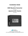
Utilizing the DMP® Vortex86DX chipsets, EPC-1800 series is a compact size and powerful PAC
(Programmable Automation Controller). EPC-1800 provides features including a Motionnet master, a USB
interface, 10/100T Ethernet LAN port and a local DIO interface.EPC-1800 with its fanless design offers
noise-free, ultra reliable operating in the most demanding of industrial environments.
Motionnet is a high-speed serial communication system, a digital serial control interface for communication
between host algorithm and axis-controllers, input/output (I/O) devices and other devices. The EPC-1800 is
an ideal system for industrial automation, machine automation and motion control markets.
1.1. Overview
Figure 1-1: overview of the EPC-1800
7
EPC-1800 Series User Manual
1.2. Hardware Specifications
CPU
•
DMP Vortex86DX 800MHz
Memory
•
SDRAM 256MB DDR2
Operating System
•
•
WinCE 5.0 (softPLC version)
WinCE 6.0 (programming version)
D-SUB Male Connector
EPC-1800:
D-SUB 26 Male Connector x1
• RS422/RS485 (COM1)
• RS232_9P (COM2)
• RS232_3P (COM3)
• RS232_3P (COM4)
EPC-1801 & EPC-1821
• RS232_3P (COM1)
• RS422/RS485 (COM2)
USB
•
1 x USB 2.0
Motionnet
•
•
Motionnet Master x 1 (EPC-1800, EPC-1801)
Motionnet Master x 2 (EPC-1821)
Ethernet
•
1 x RJ45 for 10/100T based LAN
Power Requirements
•
•
24V DC /300mA
Power consumption: 5W
DIO (Isolation 2.5KVDC)
•
•
4-channel input (EPC-1800)
8-channel input/8-channel output (EPC-1801, EPC-1821)
Storage
•
2GB onboard flash memory (with operating system occupied)
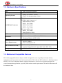
1.3. Motionnet Compatible Devices
EPC-1800 equipped Motionnet chipsets which is designed for users to quickly and easily develop
applications, such as motion control and controls of I/O. EPC-1800 and EPC-1801 have 1 Motionnet master
and EPC-1821 has 2 Motionnet masters equipped. Motionnet is a new series of products designed for
versatile automation applications, especially with motion control requirements. The built-in Motionnet will
be introduced later.
8
EPC-1800 Series User Manual
2. Dimensions and Interfaces
EPC-1800 series provides necessary input/output (I/O) interfaces. Besides often used serial communication
ports, there are user friendly interfaces including LAN and USB. In this section, the function and pin
definition of these interfaces will be illustrated.
2.1. Mechanical dimensions for all types
Figure 2-1: dimensions
9
EPC-1800 Series User Manual
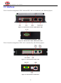
2.2. Interfaces
The I/O interface arrangement of EPC-1800 and EPC-1801 are introduced by the following figures.
Figure 2-2: main interfaces of EPC-1800 and EPC-1801
Figure 2-3: side interfaces of EPC-1800 and EPC-1801
The I/O interface arrangement of EPC-1821 is introduced by the following figures.
Figure 2-4: main interfaces of EPC-1821
Figure 2-5: side interfaces of EPC-1821
10
EPC-1800 Series User Manual
2.3. Pin Assignment for Each Connector
In the following subsections, the pin assignment for each connector will be introduced.
2.3.1. CN1 of EPC-1800
The CN1 26-pin definition of EPC-1800 is shown as below:
Pin No.
1
2
3
4
5
6
7
8
9
10
11
12
13
Definition
DCD2
RXD2
TXD2
DTR2
DGND
DSR2
RTS2
CTS2
RI2
DGND
RXD3
TXD3
DGND
Description
Pin No.
Data carrier detect
14
RX
15
TX
16
Data terminal ready
17
st
1 RS232 DGND
18
Data set ready
19
Request to send
20
Clear to send
21
Ring indicator
22
DGND
23
rd
3 RS232 RX
24
rd
3 RS232 TX
25
rd
3 RS232 DGND
26
Definition
RXD4
TXD4
DGND
R+
RT+
TDGND
DI3
DI2
DI1
DI0
GND
Table 2-1: pin assignment of DI/O interface of EPC-1800
Digital GPIO input signal circuit in SINK mode (NPN) is illustrated as follows.
Figure 2-6: DI NPN logic circuit of EPC-1800
11
Description
4th RS232 RX
4th RS232 TX
4th RS232 DGND
RS422/485 R+
RS422/485 RRS422/485 T+
RS422/485 TRS422/485 DGND
Digital input 3
Digital input 2
Digital input 1
Digital input 0
DI ground
EPC-1800 Series User Manual
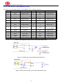
2.3.2. CN1 of EPC-1801 and EPC-1821
The CN1 26-pin definition of EPC-1801 andEPC-1821 is shown as below:
Pin No.
Definition
Description
Pin No.
Definition
Description
1
DO0
Digital output 0
14
DI6
Digital input 6
2
DO1
Digital output 1
15
DI5
Digital input 5
3
DO2
Digital output 2
16
DI4
Digital input 4
4
DO3
Digital output 3
17
R+
RS422/485 R+
5
DO4
Digital output 4
18
R-
RS422/485 R-
6
DO5
Digital output 5
19
T+
RS422/485 T+
7
DO6
Digital output 6
20
T-
RS422/485 T-
8
DO7
Digital output 7
21
option
Grounding for RS422
Else for RS485
9
GND
Ground
22
DI3
Digital input 3
10
GND
Ground
23
DI2
Digital input 2
11
RXD3
RS232 RX
24
DI1
Digital input 1
12
TXD3
RS232 TX
25
DI0
Digital input 0
13
DI7
Digital input 7
26
GND
Ground
Table 2-2: pin assignment of DI/O interface of EPC-1801 and EPC-1821
Figure 2-7: DI NPN logic circuit of EPC-1801 and EPC-1821
Figure 2-8: DO0~DO3 NPN logic circuit of EPC-1801 and EPC-1821
12
EPC-1800 Series User Manual
Figure 2-9: DO4 ~ DO7 NPN logic circuit of EPC-1801 and EPC-1821
Figure 2-10: RS422/RS485 wiring illustration of EPC-1801 and EPC-1821
Note that the “option” signal needs to be connected to GND for using of RS422.
2.3.3. Side 24V DC Input
Pin No.
Definition
Description
1
24V
24V DC power input
2
GND
Ground
3
FG
Frame ground
Table 2-3: power connector pin definition
2.3.4. Motionnet Interface
Pin Pin Mark
Pin Description
1
NC
Reserved
2
NC
Reserved
3
RS485+
4
NC
Reserved
5
NC
Reserved
6
RS485-
7
NC
Reserved
8
NC
Reserved
Motionnet protocol +
Motionnet protocol -
Table 2-4: pin definition of the Motion Ring
13
EPC-1800 Series User Manual
2.3.5. RS1 – Rotary switch
The rotary switch on the EPC-1800 series controller is for specifying the application executable to be
brought up when system is up and running. 0 is default and no application will be running. 1 is for
MyConfig server and 2 is for MyLink server. 3 and 4 are reserved for MULTIPROG related settings. 5 and 6
are available for users to set when the user application needs to be running when system is up. Via
MyConfig can configure the auto execution settings.
RS1 value
Operating Mode
Details
0
MyConfig Server Mode
Set default IP address 192.168.1.100
1
MyConfig Server Mode
2
MyLink Server Mode
3
Backup
Backup whole system to CF card
4
Restore
System restore from CF card
5
User define
Set user application via MyConfig
6
User define
Set user application via MyConfig
7
KW Mode + Modbus Slave over RTU
Cold
8
KW Mode + Modbus Slave over RTU
Stop
9
KW Mode + Modbus Slave over RTU
Warm
A
KW Mode + Modbus Slave over TCP
Cold
B
KW Mode + Modbus Slave over TCP
Stop
C
KW Mode + Modbus Slave over TCP
Warm
D
KW Mode
Cold
E
KW Mode
Stop
F
KW Mode
Warm
14
EPC-1800 Series User Manual
3. Motionnet Introduction
3.1. What Is Motionnet?
Motionnet is a super high-speed serial communication system. The G9000 devices provide input/output (I/O)
control, motor control, CPU emulation and message communication with high speed serial communications
(up to 20Mbps) all of which are required by current Factory Automation techniques. Motionnet always
transfers 4 bytes of data in 15.1μsec using cyclic communication to control input and output. While this data
is being transferred, it can communicate a maximum of 256 bytes, such as motor control data, and the LSI
controls the data transmission using interrupts. Communication times can be calculated using formulas,
allowing users to see that Motionnet guarantees the real-time oriented support needed by FA industries.
3.2. Motionnet Functions
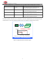
Figure 3-1: Motionnet system architecture
Provides a communication protocol based on the RS485 standard.
Can communicate variable length of data from 1 to 128 words (when a 16-bit CPU is used)
An LSI central device (G9001) controls the bus.
I/O wiring can be greatly reduced by using a G9002 I/O device.
Motor control wiring can be reduced by using a G9003 PCL.
Using a G9004 CPU emulation device reduces the wiring for general devices connected to a CPU. Data
can be exchanged between CPUs by changing the G9004 mode.
New devices can be added to the system on the fly.
Systems can be isolated using pulse transformers.
Transfer speed up to 20 Mbps.
15
EPC-1800 Series User Manual
Maximum 64 slave devices for each serial line on a master device.I/O control of up to 256 ports (2048
points), motion control of up to 64 axes, and LSI control of up to 128 devices.
I/O and status communication time for each device when inputting/outputting and reading status data
for each device, the system automatically refreshes the center device RAM each communication
cycle.(Cyclic communication: 15.1 µsec./local device)When 32 local devices are connected (1024
points of I/O): 0.49 msec. When 64 local devices are connected (2048 points of I/O): 0.97 msec.
Data communication time cyclic communication can be interrupted with a command from the CPU.
Data communication time: 19.3 µsec. to send or receive 3 bytes (e.g. when writing feed amount data to
the G9003).Data communication time: 169.3 µsec. to send or receive 256 bytes.
Serial communication connection cable. Multi-drop connections using LAN cables or dedicated cables.
Total cable length of one line: 100 m (20 Mbps/32 local boards) (10 Mbps/64 local boards).Cable
length between local boards: 0.6 m or longer.
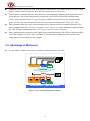
3.3. Advantage of Motionnet
It is possible to connect from center to terminal controller parts by one cable.
SENSOR
SENSOR
SENSOR
SENSOR
SENSOR
SENSOR
SENSOR
SENSOR
ACTUATOR
ACTUATOR
ACTUATOR
ACTUATOR
ACTUATOR
ACTUATOR
ACTUATOR
ACTUATOR
ACTUATOR
ACTUATOR
MOTOR
Motion.NET
100m
Extension
Analog I /O
SENSOR
SENSOR
SENSOR
SENSOR
SENSOR
SENSOR
SENSOR
SENSOR
Digital I /O
Master
Motion
ACTUATOR
ACTUATOR
ACTUATOR
ACTUATOR
ACTUATOR
ACTUATOR
ACTUATOR
ACTUATOR
ACTUATOR
ACTUATOR
MOTOR
WIRE-SAVING / LONG-DISTANCE
Figure 3-2: wire-saving and long-distance support
16
EPC-1800 Series User Manual
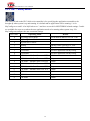
In cyclic communication, a communication cycle is as follows when a 20 Mbps speed is selected.
Number of local devices
Communication cycle
Remarks
8
0.12 ms
If all of the local devices connected are I/O
devices, 256 I/O points can be used.
16
0.24 ms
If all of the local devices connected are I/O
devices, 512 I/O points can be used.
32
0.49 ms
If all of the local devices connected are I/O
devices, 1024 I/O points can be used.
64
0.97 ms
If all of the local devices connected are I/O
devices, 2048 I/O points can be used.
If a different number of local devices are connected, or when the communication cycle is interrupted by data
communications, refer to the calculation formulas in the user's manual to calculate the time latency.
Master
CYCLE TIME
20Mbps
Slave Module
x 64 Slave
64 Slaves < 1.04ms
1.04ms
0.56ms
32
512 -DI / 512-DO
64
NODE
1024 -DI / 1024-DO
On 20Mbps , Max. Cycle Time = 15.1 x NODE + 71.4 [FIFO Time] in us
HIGH-SPEED / TIME-DETERMINISTIC
Figure 3-3: high-speed and time deterministic support
17
EPC-1800 Series User Manual
4. Software Utilities
There are two software utilities provided to help users easily make use of EPC-1800.
1. MyConfig – for configuring the settings in EPC-1800.
2. MyLink – for diagnosing and testing functionality of Motionnet modules.
4.1. MyConfig
MyConfig is a software utility designed for EPC-1800. Besides providing basic hardware information,
MyConfig also supports online updates so that users can set and view the hardware status through Ethernet.
Recommended Hardware Requirement
PC Hardware: PC or laptop with Intel Centrino or above CPU
Memory: 1GBRAM
OS: Windows XP or Win7
LAN card: RJ-45 10/100/1000 Mbps
Software Installation
EasyPAC needs 2 files: MyConfigSvr.exe and EZPACSDK.dll
PC needs 1 file: MyConfig.exe
4.1.1. Server on EPC-1800 series
Before powering up EPC-1800, please make sure the SW1 is switched to position 1. PC is supposed to have
the same network section as EPC-1800 (IP address: 192.168.1.100) when the network cable is hooked up. If
these two settings are correct, we can power up the EPC-1800. It will beep an alert sound if the system is
successfully brought up and MyConfigSrv.exe will be started automatically. If there is no beep for a while,
that means that there is Ethernet failure or the IP address is in conflict with someone else.
4.1.2. PC side settings
4.1.2.1 Login
Users can login MyConfig with EPC-1800 IP address and password. MyConfig provides two kinds of login
accounts which have different privileges. The default password for an administrator is admin and the default
password for a guest is guest. The password canbe updated after the initial login. The administrator has the
privilege to view and change settings, and the guest can only view the current settings. Below illustrates the
case of an administratorinitially logging in with rotary switch set to 0, and using default IP address
192.168.1.100.
18
EPC-1800 Series User Manual
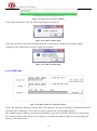
Figure 4-1: MyConfig login page
After logging in, there are 6 tabs – PAC info, Auto Execute, Update, AES code, Modbus Parameters and
About MyConfig.
Figure 4-2: system information of EasyPAC
4.1.2.2 PAC Info
Users can see the EPC-1800 basic hardware information at the top half of the page. At the bottom half, users
can set up IP addresses, subnet masks, gateways, admin passwords and guest passwords.
19
EPC-1800 Series User Manual
Figure 4-3: Hardware basic information
Figure 4-4: change settings of IP, subnet mask, gateway, admin and guest password
Note that only if the user is in the same network section can they change the EPC-1800 IP address. The IP
address, subnet mask and gateway settings can be saved if the “Save” button is hit. This save will take effect
after restarting the system. The admin and guest password will change immediately when new a password is
input and “Save” button is pressed.
4.1.2.3 Update
It provides an online software update. Please make sure the PC is connected to the internet before an online
update. If the “Check for Updates” button is pressed, it will show up the software versions on EPC-1800 and
user’s PC at the top half. At the bottom half it shows the latest software versions provided from TPM.
Figure 4-5: connect to FTP server
The upper frame shows information including 1: PC side version, 2: EasyPAC side version and 3: the latest
version in FTP site. If the older version displays “?.?”it means that there is one or more components which
do not match with the newer version ones.
20
EPC-1800 Series User Manual
Figure 4-6: update software page
In this “Update” tab, it would show up the software versions that are out of date. There is also a hint
message informing when software needs to be updated. After the OK button is pressed, MyConfig starts
connecting to the FTP server and downloading files.
Figure 4-7: download from FTP
Upload to EPC-1800.
Figure 4-8: update to EasyPAC
When select files need to be updated press the “Start Update” button and it will start updating and a pop-up
progress bar, like the one below, will appear.
21
EPC-1800 Series User Manual
Figure 4-9: progress bar of software updating
If the update includes PC only, the following dialog box will pop up.
Figure 4-10: update complete dialog
If the software update completes including EasyPAC, it will pop up a dialog box saying the update
completed. EPC-1800 needs to reboot to apply new software.
Figure 4-11: update complete dialog
4.1.2.4 AES Code
Figure 4-12: dialog window for generating AES key
Secure ID: display the hardware id of the EPC-1800. Moreover, the system integrator caninput the hardware
id of other EPC-1800 in the “Secure ID” text box to generate the corresponding AES key.
EPC-1800provides an AES key encryption mechanism to protect our customers. The SI key is supposed to
be 16 numeric digits. If the SI key is not 16 digits or it contains non-numeric digits, an error message will
show up as the figure below.
22
EPC-1800 Series User Manual
Figure 4-13: insufficient digits
4.1.2.5 Modbus Parameter
The “Modbus Parameters” page lets users edit Modbus related parameters for KW applications of EasyPAC.
Modbus requires settings of slave ID, TCP and RTU parameters. MyConfig provides sets of default settings
in advance. Users can change the settings and press the “Save Settings” button to transmit the settings to
EasyPAC.
Next time when users login to MyConfig, the prior settings or the default values will be shown in the
Modbus parameters page. Users can always login to check in this page. This page is shown in the following
figure.
23
EPC-1800 Series User Manual
Figure 4-14: setting of Modbus parameter dialog
4.1.2.6 Recover Factory Default Settings
If users forget the changed password of admin or guest, or the changed settings of the IP, Modbus, etc is not
working, a solution is to recover the factory settings. The step-by-step recovery from factory settings is as
follows:
1.
Press the recovery button
2.
The EPC-1800 would roll back to the default IP address: 192.168.0.100. Now we could connect to it
with MyConfig.
The “PAC info” tab has previous set IP address shown in “Saved IPAddress”.
3.
and then reboot.
24
EPC-1800 Series User Manual
5. Project Encryption
This chapter is intended to give a brief overview of the project encryption for EPC-1800. The following
section will give background information that is necessary to fully understand the functions and how to
achieve hardware encryption of the system.
5.1. Benefits
TPM is a development system provider with EPC-1800 as one of the products. System integrators could
adapt EPC-1800 as the base system to develop applications for their customers. However, customers could
find the top source vendor which is TPM and perhaps, in the worst case, clone the storage in the system and
purchase extra systems from TPM directly. In case of customers bypassing the original system provider,
which would cut down benefits for the system integrators cooperating with TPM, EPC-1800 introduces a
method called project encryption. Through project encryption, the system integrators can lockup certain
functionalities or set timers to constrain the system running time. Only the authorized products can be
working properly. The authorization is held by one, and only one, system integrator.
With the project encryption technology, the system integrators cooperating with TPM will be tightly coupled
in a cooperating relationship, instead of vicious competition to make a win-win partnership.
5.2. AES Brief Introduction
This standard specifies the Rijndael algorithm, a symmetric block cipher that can process data blocks of 128
bits, using cipher keys with lengths of 128, 192, and 256 bits. Rijndael was designed to handle additional
block sizes and key lengths; however, they are not adopted in this standard. Throughout the remainder of
this standard, the algorithm specified herein will be referred to as “the AES algorithm.” The algorithm may
be used with the three different key lengths indicated above, and therefore these different “flavors” may be
referred to as “AES-128”, “AES-192”, and “AES-256”.
Since the AES encryption/decryption algorithm is not the main function of EPC-1800, the detailed
introduction is not introduced in this manual. Please refer to Wikipedia for more information.
5.3. Functional Architecture
Each EPC-1800 is equipped with an identification chip that has a unique serial number. The unique serial
number plays the role as the content for AES algorithm. We will call the unique serial number the “hardware
id” from now on. Another key held by the system integrator is called the SI key, used for
encryption/decryption for the AES algorithm to make the registration key. The illustration of the making of
the registration is as the following figure.
25
EPC-1800 Series User Manual
Figure 5-1: generation of the registration key
From the above figure, the hardware id is obtainable within EPC-1800, taken as the content for the AES
algorithm. The SI key, hard coded by the system integrator, is the key to calculate the output value and the
registration key. The registration key is like the activation code to activate the full functionalities of the
EPC-1800 and it is not invertible. Even though the whole data including the registration key could be cloned,
the end user or the system integrator’s customer cannot obtain the SI key. If an end user wants to buy a
replacement from other resources instead of the designated system integrator, it is not doable since the
hardware id would be different with the original one. Therefore, the calculated registration key with the
original SI key and different hardware id as content would not match so that the specific functionalities
could not be working or the system could only run for certain time period.
Once the system integrator gets EPC-1800, a very important thing needed to do is to assign a set of SI key
with a byte array of length 8 to it. With this SI key, the system integrator can generate the AES key (byte
array of length 16) using the provided function application interface _ezpac_generate_aes_key. This function
will be introduced later. The generated AES key should be given to end users as the activation code when the
user brings up the system at first time. AnEPC-1800 should check the validity and set the corresponding flag
in the FRAM right after the system initialization using function _ezpac_verify_aes_key,
_ezpac_write_fram_byte. Hereafter, when the system is brought up, it reads the flag from FRAM. If the read
value matches the pre-defined value, the system bypasses the check AES key procedure and operates
normally as the system integrator designed. If the values from the designated address in FRAM do not match,
the system could only run a certain time or some advanced functions become locked. Only with the correct
activation code can you bring the system up with full functionalities and unlimited running time.
26
EPC-1800 Series User Manual
6. Software Development Environment
6.1. System Requirements
The sections below describe the system and software requirements for developing EPC-1800 applications.
Note that the programming using C/C++/C# needs to check the following settings for the environment. If the
programming is through KW MULTIPROG, please refer to MULTIPROG programming manual.
6.1.1. Hardware Requirements
Processor: 1 GHz
RAM: 256MB
Available hard disk space: 3GB
6.1.2. Software Requirements
Operating system: Microsoft Windows XP or 7
SDK: Microsoft Visual Studio 2005
Need service pack 1 and .NET compact framework 2.0 service pack 1 installed
SDK: Microsoft Visual Studio 2008
Need service pack 1 installed
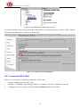
If there are connection problems on online debugging, please copy the 5 online debug files from
developing PC to EPC-1800 and try again. Once the files are copied to the specified location on
EPC-1800, it will be copied to folder \Windows automatically after restarting the system.
The location of the online debug files would be located at described below.
Windows XP/7 32-bit OS (source):as shown in figure 7-1
C:\Program Files\Common Files\microsoft shared\CoreCon\1.0\Target\wce400\x86\*.*.
Windows 7 64 Bit OS (source): as shown in figure 7-1
C:\Program Files (x86)\Common Files\microsoft shared\CoreCon\1.0\Target\wce400\x86\*.*.
27
EPC-1800 Series User Manual
Figure 6-1: file path for remote debugger files
EPC-1800 (destination):
\USB\Project
Transfer the files from PC to EPC-1800 using FTP software. The destination location of EPC-1800 is
\USB\Project. The account to log in FTP service of the EPC-1800 is account: admin and password: admin.
6.2. Online Debugging
Online debugger is a very useful tool when developers are developing their projects. EPC-1800 also
provides an online debugger mechanism to help users easily online debug and monitor variables. There are
some preliminaries need to prepare of both developing PC and EPC-1800 before starting the online
debugging.
6.2.1. Check the Ethernet IP Address of the EPC-1800
Configure the IP address by using MyConfig. In the following instances, 192.168.1.130 is used as an
example.
Please make sure the IP address of EPC-1800 and the SDK machine are in the same network subnet.
SmartPAC is the server of the running application and connected with the SDK machine to achieve online
debugging. The Sequence to establish a connection to the EPC-1800 will be introduced next.
6.2.2. Create a New Project
When create a new EPC-1800 project, please select “Smart Device” → “Windows CE 5.0” as the project
type as shown in the follow figure.
28
EPC-1800 Series User Manual
Figure 6-2: select Windows CE 5.0 as the project type
Go to the properties of the project and uncheck the checkbox of “Deploy the latest version of .NET Compact
Framework (including Service Packs) as shown below.
Figure 6-3: uncheck the checkbox highlighted
6.2.3. Connect to EPC-1800
There are several steps to establish a connection to EPC-1800.
1. Open the sample project for EPC-1800.
Example: C:\TPM\EPC-1800\Samples\VS2005_VC\Platform_demo(VC)\Platform_demo.sln
2.
Configure the device option by selecting Tools Options in the function menu.
29
EPC-1800 Series User Manual
Figure 6-4: tools - options
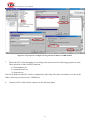
3.
4.
5.
6.
Configure the target device IP address
It is necessary to configure the target IP address before making a connection. This could be done
through “Device Tools Devices” from the option window as the 1st step in Figure 6-5.
Select the target device (EPC-1800 for this example) as marked as the 2nd step in Figure 6-5 and hit the
“Properties…” button as the 3rd step.
The EPC-1800 properties dialog will be popped-up. Click the “Configure…” button to configure as the
4th step in Figure 6-5.
Specify the target IP address and click OK button to finish the configuration process as shown as the 5th
and 6th step in Figure 6-5.
30
EPC-1800 Series User Manual
Figure 6-5: step sequence to configure the target device IP address for SDK machine
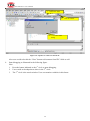
7.
Launch the EPC-1800 debugging service using telnet and execute the following programs in order.
There should be 2 telnet consoles launched.
1. Clientshutdown.exe
2. ConmandClient2.exe
3. CMAccept.exe
Note the IP address of the EPC-1800 is configured by MyConfig. The three executables are in the in the
folder created in previous section, \USB\Project
8.
Connect to EPC-1800 with the sequence in the following figure.
31
EPC-1800 Series User Manual
3.
Select EPC-1800
2.
1.
Click to connect
Connection status
dialog
Figure 6-6: sequence to connect to SmartPAC
9.
Also users could select hit the “Close” button to disconnect from EPC-1800 as well.
Start debugging as illustrated in the following figure.
Note.
1. Press the button indicated as the 1st circle to start debugging.
2. Users could set breakpoints as show in the 2nd circle.
3. The 3rd circle is the watch window. Users can monitor variables in this frame.
32
EPC-1800 Series User Manual
Figure 6-7: the debugging window
33
EPC-1800 Series User Manual
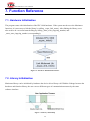
7. Function Reference
7.1. Hardware Initialization
The program starts with initialization of the EPC-1800 hardware. If the system needs to use the Motionnet
functions, it is necessary to link the library by calling _ezpac_link_mnet(). After linking the library, users
also need to do a reset and start the Ring by calling _mnet_reset_ring(ring_number) and
_mnet_start_ring(ring_number) correspondingly.
Figure 7-1: hardware initialization interface
7.2. Library Initialization
Motionnet library can be initialized by hardware the device driver library call. With the Linkage between the
hardware and function library, the user can use different types of communication masters by the same
software interface.
Figure 7-2: library relationship
34
EPC-1800 Series User Manual
7.3. Motionnet Master
The operation of Motionnet extension is divided into the following 2 groups. One is the Motionnet master
device, the other is the slave device.
Figure 7-3: illustration of master-slave
7.4. Data Definition
Type
Description
Range
U8
8-bit ASCII character
0 to 255
I16
16-bit signed integer
-32768 to 32767
U16
16-bit unsigned integer
0 to 65535
I32
32-bit signed long integer
-2147483648 to 2147483647
U32
32-bit unsigned long integer
0 to 4294967295
F32
32-bit single-precision
floating-point
-3.402823E38 to 3.402823E38
F64
64-bit double-precision
floating-point
-1.797683134862315E308 to 1.797683134862315E309
Boolean
Boolean logic value
TRUE, FALSE
35
EPC-1800 Series User Manual
7.5. Platform Functions
7.5.1. Platform Information Functions
Function name
Description
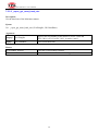
_ezpac_initial
Initialize EPC-1800 platform.
_ezpac_get_device_type
Retrieve the type of the platform. It will return EPC-1800 for this case.
_ezpac_beep
Set the buzzer on for specified time.
_ezpac_beep_start
Turn on or off the buzzer.
_ezpac_read_rotary_switch_1
Read the number of the rotary switch.
36
EPC-1800 Series User Manual
7.5.1.1 _ezpac_initial
Description:
Initialize EPC-1800 platform
Syntax:
I16 _ezpac_initial()
Argument:
None
Return:
PLATFORM_NoError
The API is successfully returned.
Others
Please refer to the error code table at Appendix A.
37
EPC-1800 Series User Manual
7.5.1.2 _ezpac_get_device_type
Description:
Retrieve the type of the platform. It will return EPC-1800 for this case.
Syntax:
I16 _ezpac_get_device_type(U8* Type)
Argument:
[input]
U8* Type
Return the type of the controller.
Return:
PLATFORM_NoError
The API is successfully returned.
Others
Please refer to the error code table at Appendix A.
38
EPC-1800 Series User Manual
7.5.1.3 _ezpac_beep
Description:
Set the buzzer on for specified time.
Syntax:
I16 _ezpac_beep(U32 Duration)
Argument:
[output]
U32 Duration
Duration that the buzzer is set to on.
Return:
PLATFORM_NoError
The API is successfully returned.
Others
Please refer to the error code table at Appendix A.
39
EPC-1800 Series User Manual
7.5.1.4 _ezpac_beep_start
Description:
Turn on or off the buzzer.
Syntax:
I16 _ezpac_beep_start(U8 OnOff)
Argument:
[output]
U8 OnOff
Set on or off of the buzzer.
Return:
PLATFORM_NoError
The API is successfully returned.
Others
Please refer to the error code table at Appendix A.
40
EPC-1800 Series User Manual
7.5.1.5 _ezpac_read_rotary_switch_1
Description:
Read the number of the rotary switch.
Syntax:
I16 _ezpac_read_rotary_switch_1(U8 *Val)
Argument:
[input]
U8 *Val
The number of the rotary switch.
Return:
PLATFORM_NoError
The API is successfully returned.
Others
Please refer to the error code table at Appendix A.
41
EPC-1800 Series User Manual
7.5.2. Platform I/O Functions
Function name
Description
_ezpac_get_led0
Get the status of LED 1
_ezpac_set_led0
Set the status of LED 1
_ezpac_get_led3
Get the status of LED 2
_ezpac_set_led3
Set the status of LED 2
_ezpac_read_lio
Read local DI
42
EPC-1800 Series User Manual
7.5.2.1 _ezpac_get_led0
Description:
Get the status of LED 1
Syntax:
I16 _ezpac_get_led0(U8* OnOff)
Argument:
[input]
U8 *OnOff
Return the status of LED 1.
Return:
PLATFORM_NoError
The API is successfully returned.
Others
Please refer to the error code table at Appendix A.
43
EPC-1800 Series User Manual
7.5.2.2 _ezpac_set_led0
Description:
Set the status of LED 1
Syntax:
I16 _ezpac_set_led0 (U8 OnOff)
Argument:
[Output]
U8 Data
Set the value of LED 1.
Return:
PLATFORM_NoError
The API is successfully returned.
Others
Please refer to the error code table at Appendix A.
44
EPC-1800 Series User Manual
7.5.2.3 _ezpac_get_led3
Description:
Get the status of LED 2
Syntax:
I16 _ezpac_get_led3(U8* OnOff)
Argument:
[input]
U8* OnOff
Return the status of LED 2.
Return:
PLATFORM_NoError
The API is successfully returned.
Others
Please refer to the error code table at Appendix A.
45
EPC-1800 Series User Manual
7.5.2.4 _ezpac_set_led3
Description:
Set the status of LED 2
Syntax:
I16 _ezpac_set_led3(U8 OnOff)
Argument:
[output]
U8 Data
Set the value of LED 2.
Return:
PLATFORM_NoError
The API is successfully returned.
Others
Please refer to the error code table at Appendix A.
46
EPC-1800 Series User Manual
7.5.2.5 _ezpac_read_lio
Description:
Read local DI.
Syntax:
I16 _ezpac_read_lio(U8* Val)
Argument:
[input]
U8* Val
Return the status of local DI
Return:
PLATFORM_NoError
The API is successfully returned.
Others
Please refer to the error code table at Appendix A.
47
EPC-1800 Series User Manual
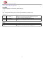
7.5.3. Motionnet Related Functions
Function name
Description
_ezpac_link_mnet
Activate the Motionnet master.
_ezpac_get_mnet_baud_rate
Get the baud rate of the Motionnet master.
_ezpac_set_mnet_baud_rate
Set the baud rate of the Motionnet master.
48
EPC-1800 Series User Manual
7.5.3.1 _ezpac_link_mnet
Description:
Activate the Motionnet master.
Syntax:
I16 _ezpac_link_mnet ()
Argument:
None
Return:
PLATFORM_NoError
The API is successfully returned.
Others
Please refer to the error code table at Appendix A.
49
EPC-1800 Series User Manual
7.5.3.2 _ezpac_get_mnet_baud_rate
Description:
Get the baud rate of the Motionnet master.
Syntax:
I16 _ezpac_get_mnet_baud_rate (U16 RingNo, U8* BaudRate)
Argument:
[output]
U16 RingNo
Specify the ring number of the master. For EPC-1800 and
EPC-1801, it is 0. For EPC-1821, it can be 0 and 1.
[input]
U8* BaudRate
The current baud rate.
Return:
PLATFORM_NoError
The API is successfully returned.
Others
Please refer to the error code table at Appendix A.
50
EPC-1800 Series User Manual
7.5.3.3 _ezpac_set_mnet_baud_rate
Description:
Set the baud rate of the Motionnet master.
Syntax:
I16 _ezpac_set_mnet_baud_rate (U16 RingNo, U8 BaudRate)
Argument:
[output]
U16 RingNo
Specify the ring number of the master. For EPC-1800 and
EPC-1801, it is 0. For EPC-1821, it can be 0 and 1.
[output]
U8* BaudRate
The baud rate to be set.
Return:
PLATFORM_NoError
The API is successfully returned.
Others
Please refer to the error code table at Appendix A.
51
EPC-1800 Series User Manual
7.5.4. Platform AES Functions
Function name
Description
_ezpac_get_secure_id
Get the SECURE_ID of the system in 8 bytes array format.
_ezpac_generate_aes_key
Generate the AES_KEY with SI_KEY and SECURE_ID.
_ezpac_verify_aes_key
Check the validity of the generated AES_KEY.
52
EPC-1800 Series User Manual
7.5.4.1 _spc2_get_secure_id
Description:
Get the SECURE_ID of the system in 8 bytes array format.
Syntax:
I16 _ezpac_get_secure_id (U8 SecureID[8])
Argument:
[input]
U8 SecureID[8]
Pointer to an 8-byte array indicating the Secure ID. If SecureId is
not null, the data read from security ASIC will be used to
generate AES_KEY.
Return:
PLATFORM_NoError
The API is successfully returned.
Others
Please refer to the error code table at Appendix A.
53
EPC-1800 Series User Manual
7.5.4.2 _ezpac_generate_aes_key
Description:
Generate the AES_KEY with SI_KEY and SECURE_ID.
Syntax:
I16 _ezpac_generate_aes_key (U8 SI_Key[16], U8 SecureID[8], U8 AES_Key[16])
Argument:
[output]
U8 SI_KEY[16]
Pointer to a 16-element byte-array indicating SI key.Every
element is an integer ranged from 0 to 9.
[output]
U8 SecureId[8]
Input the 8-byte array indicating the Secure ID.
[input]
U8 AES_KEY[16]
The generated AES_KEY in 16-byte array format.
Return:
PLATFORM_NoError
The API is successfully returned.
Others
Please refer to the error code table at Appendix A.
54
EPC-1800 Series User Manual
7.5.4.3 _ezpac_verify_aes_key
Description:
Check the validity of the generated AES_KEY.
Syntax:
I16 _ezpac_verify_aes_key (U8 SI_Key[16], U8 AES_Key[16], U8* Validity)
Argument:
[output]
U8 SI_KEY[16]
[output]
U8 AES_KEY[16]
[input]
U8 *Validity
Pointer to a 16-element byte-array indicating SI key.Every
element is an integer ranged from 0 to 9.
Input the 16-byte array indicating the AES_KEY.
The result of the checking. 0: invalid,1: valid
Return:
PLATFORM_NoError
The API is successfully returned.
Others
Please refer to the error code table at Appendix A.
55
EPC-1800 Series User Manual
AES Key Example:
U8 SID[8];
U8 SIK[16] = {1,2,3,4,5,6,7,8,9,0,1,2,3,4,5,6};
U8 AesKey[16];
U8 Validity;
//every element is an integer ranged from 0 to 9
// Generate AES Key
_ezpac_initial();
_ezpac_get_secure_id(SID);
_ezpac_generate_aes_key(SIK, SID, AesKey);
// Check AES Key
_ezpac_verify_aes_key(SIK, AesKey, ref Validity);
Secure ID Array
09
e8
1b
f6
05
00
00
05
[7]
[6]
[5]
[4]
[3]
[2]
[1]
[0]
SI Key Array
1
2
3
4
5
6
[15] [14] [13] [12] [11] [10]
7
8
9
0
1
2
3
4
5
6
[9]
[8]
[7]
[6]
[5]
[4]
[3]
[2]
[1]
[0]
AES Key Array
9507
f73e
8bb9
5a78
d4a7
48dc
bb4a
537b
[15][14]
[13][12]
[11][10]
[9][8]
[7][6]
[5][4]
[3][2]
[1][0]
56
EPC-1800 Series User Manual
7.5.5. Platform Retain Functions
Function name
Description
_ezpac_read_fram_byte
Read a byte data from a retainable memory.
_ezpac_read_fram_word
Read a word data from a retainable memory.
_ezpac_read_fram_dword
Read a double word data from a retainable memory.
_ezpac_write_fram_byte
Write a byte data to a retainable memory.
_ezpac_write_fram_word
Write a word data to a retainable memory.
_ezpac_write_fram_dword
Write a double word data to a retainable memory.
57
EPC-1800 Series User Manual
7.5.5.1 _ezpac_read_fram_byte
Description:
Read a byte data from a retainable memory.
Syntax:
I16 _ezpac_read_fram_byte(U16 Offset, U8* Val)
Argument:
[output]
U16 Offset
Specify the offset the retainable memory.
[input]
U8* Val
Return the value of the retainable memory.
Return:
PLATFORM_NoError
The API is successfully returned.
Others
Please refer to the error code table at Appendix A.
58
EPC-1800 Series User Manual
7.5.5.2 _ezpac_read_fram_word
Description:
Read a word data from a retainable memory.
Syntax:
I16 _ezpac_read_fram_word(U16 Offset, U16* Val)
Argument:
[output]
U16 Offset
Specify the offset the retainable memory.
[input]
U16* Val
Return the value of the retainable memory.
Return:
PLATFORM_NoError
The API is successfully returned.
Others
Please refer to the error code table at Appendix A.
59
EPC-1800 Series User Manual
7.5.5.3 _ezpac_read_fram_dword
Description:
Read a double word data from a retainable memory.
Syntax:
I16 _ezpac_read_fram_dword(U16 Offset, U32* Val)
Argument:
[output]
U16 Offset
Specify the offset the retainable memory.
[input]
U32* Val
Return the value of the retainable memory.
Return:
PLATFORM_NoError
The API is successfully returned.
Others
Please refer to the error code table at Appendix A.
60
EPC-1800 Series User Manual
7.5.5.4 _ezpac_write_fram_byte
Description:
Write a byte data to a retainable memory.
Syntax:
I16 _ezpac_write_fram_byte(U16 Offset, U8 Val)
Argument:
[output]
U16 Offset
Specify the offset the retainable memory.
[output]
U8 Val
Set the value of the retainable memory.
Return:
PLATFORM_NoError
The API is successfully returned.
Others
Please refer to the error code table at Appendix A.
61
EPC-1800 Series User Manual
7.5.5.5 _ezpac_write_fram_word
Description:
Write a word data to a retainable memory.
Syntax:
I16 _ezpac_write_fram_word(U16 Offset, U16 Val)
Argument:
[output]
U16 Offset
Specify the offset the retainable memory.
[output]
U16 Val
Set the value of the retainable memory.
Return:
PLATFORM_NoError
The API is successfully returned.
Others
Please refer to the error code table at Appendix A.
62
EPC-1800 Series User Manual
7.5.5.6 _ezpac_write_fram_dword
Description:
Write a double word data to a retainable memory.
Syntax:
I16 _ezpac_write_fram_dword(U16 Offset, U32 Val)
Argument:
[output]
U16 Offset
Specify the offset the retainable memory.
[output]
U32 Val
Set the value of the retainable memory.
Return:
PLATFORM_NoError
The API is successfully returned.
Others
Please refer to the error code table at Appendix A.
63
EPC-1800 Series User Manual
8. Appendix A
8.1. The Platform Error Code List Table
PLATFORM_NoError
0
PLATFORM_NotReady_Error
-9000
PLATFORM_CheckDeviceNotMatch_Error
-9001
PLATFORM_Unknown_Error
-9005
PLATFORM_DeviceUnknown_Error
-9006
PLATFORM_Version_Error
-9010
PLATFORM_Open_File_Error
-9011
PLATFORM_Write_File_Error
-9012
PLATFORM_Read_File_Error
-9013
PLATFORM_Out_Of_Range_Error
-9020
PLATFORM_InvalidParameter_Error
-9021
PLATFORM_GetSecureIdFailed_Error
-9022
PLATFORM_GenAesKeyFailed_Error
-9023
PLATFORM_InformationType_Unknown_Error
-9030
PLATFORM_Debug_Infomation_0
-9040
PLATFORM_Debug_Infomation_1
-9041
PLATFORM_Debug_Infomation_2
-9042
PLATFORM_Debug_Infomation_3
-9043
PLATFORM_NotSucceed_Error
-9090
64
EPC-1800 Series User Manual
8.2. The Motion Error Code List Table
ERR_NoError
0
ERR_BoardNotInitYet
-14001
ERR_BoardInitializedAlready
-14002
ERR_InvalidBoardNumber
-14003
ERR_InvalidAxisNumber
-14004
ERR_InvalidParameter1
-14011
ERR_InvalidParameter2
-14012
ERR_InvalidParameter3
-14013
ERR_InvalidParameter4
-14014
ERR_InvalidParameter5
-14015
ERR_InvalidParameter6
-14016
ERR_InvalidParameter7
-14017
ERR_InvalidParameter8
-14018
ERR_InvalidParameter9
-14019
ERR_InvalidParameter10
-14020
ERR_InvalidParameter11
-14021
ERR_InvalidParameter12
-14022
ERR_SlowDownPointError
-14031
ERR_Err3PointsInput
-14032
ERR_GetCenterFailed
-14033
ERR_CompareBufferFull
-14034
ERR_AxisNotStoppedYet
-14035
65