1
AT&T
®
MERLIN II
COMMUNICATIONS SYSTEM
Feature Module 2
Data Communications Guide
©1988 AT&T
All Rights Reserved
Printed in USA
Issue 2
May, 1988
NOTICE
The information in this document is subject to change without notice. AT&T assumes no responsibility
for any errors that may appear in this document.
MERLIN is a registered trademark of AT&T
To order copies of this document, call the AT&T Customer Information Center, 1-800-432-6600 and
include the document number 518-600-039 with your order.
Contents
Section 1: Introduction
What’s in This Guide
How to Use This Guide
Data Communications with the MERLIN II System
1-1
1-2
1-3
Section 2: Planning Data Options
Planning Overview
Components of the MERLIN II System
Identifying Line and Station Modules
Reserving Line Jacks
Reserving Station Jacks for Voice and Data Workstations
Reserving Jacks for Computer Access and Modem Pools
Planning Data Hunt Groups
Master Planning Form
Incoming Modem Pool Form
Data Hunt Group Form
2-1
2-3
2-5
2-8
2-9
2-14
2-20
2-21
2-25
2-27
Section 3: Connecting Hardware and Setting Options
Installation Overview
Simultaneous Voice and Data at Digital Stations
Digital Stations for Data Communications Only
Simultaneous Voice and Data at Analog Stations
Local Host Computer Access
Modem Pools
3-1
3-2
3-6
3-7
3-9
3-12
Section 4: Administering Data Options
Administration Overview
4-1
Basic Administration for Analog Station Jacks
4.3
Modem Pools
4-4
Data Hunt Groups
4-6
The Local Host Interface Feature
4-8
Data Status Buttons for Digital Voice Terminals
4-9
Simultaneous Voice and Data at Analog Voice Terminals 4-10
Section 5: Using Data Equipment for Calls
Overview
Data Calls with Digital Voice and Data Equipment
Data Calls with an Analog Voice Terminal
Data Calls to Digital Stations from Other Locations
Special Information for Placing Data Calls
Voice Calls Dialed from a Computer or Data Terminal
Index
5-1
5-3
5-10
5-12
5-13
5-15
What’s in This Guide
The information in this guide is divided into five sections, as described below.
SECTION 1:
INTRODUCTION
This section tells what’s in the guide and how to use it. It also gives an
overview of data communications with the MERLIN®II Communications
System. In addition, it defines basic terms.
SECTION 2: PLANNING
DATA OPTIONS
This section helps system administrators make basic decisions about how to
use the data options that the MERLIN II system provides. It includes forms
for recording those decisions.
SECTION 3: CONNECTING
HARDWARE AND SETTING
OPTIONS
This section explains how to connect data hardware to the control unit and to
other equipment in the MERLIN II system. It also provides information on
setting option switches for data stands, data modules, and modems.
SECTION 4:
ADMINISTERING DATA
OPTIONS
This section shows administrators how to use the information on the planning
forms to customize the system to meet specific data communications needs,
SECTION 5: USING DATA
EQUIPMENT FOR CALLS
This section explains how to handle internal and outside data calls and how
to place voice calls from a computer or data terminal. It contains separate
instructions for people with digitaI and analog ‘voice terminals.
What’s in This Guide 1-1
How to Use This Guide
This guide to data options is intended as a supplement to the MERLIN II
System Manual that you received with your system. How you should use the
guide at any particular time depends on what you want to do.
SETTlNG UP DATA
OPTIONS FOR THE FIRST
TIME?
Use the information in Section 2, “Planning Data Options” to decide which
options you want for your system and complete the appropriate forms. If
your data equipment hasn’t been installed, follow the instructions in
Section 3, “Connecting Data Hardware and Setting Options.” (If you aren’t
experienced in hardware installation, have someone else perform this step.)
After the equipment is installed, perform the procedures in Section 4,
“Administering Data Options” that apply to your system.
MAKING CHANGES TO A
SYSTEM WITH DIGITAL
DATA CAPABILITY?
Update your planning forms to reflect the changes you want to make. Then
perform the appropriate procedure(s) in Section 4, “Administering Data
Options.” If the change requires changing hardware or hardware option
settings, see Section 3, “Connecting Hardware and Setting Options.”
MAKING A DATA CALL
FOR THE FIRST TIME?
See the relevant entries in Section 5, “Using Data Equipment for Calls."
How to Use This Guide 1-2
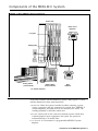
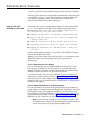
Data Communications with the MERLIN II System
The MERLIN II system provides for simultaneous voice and data
communications using internal or outside telephone lines. A person with a
data terminal or personal computer can make a data call to a host computer,
for example, then place or receive voice calls without affecting the data
connection.
SYSTEM COMPONENTS
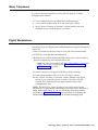
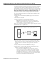
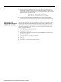
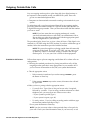
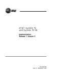
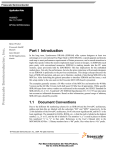
Figure 1-1 shows how data and voice equipment is connected in the
MERLIN II system. As this illustration shows, the system can accommodate
several different types of voice and data workstations. Two special features
of the MERLIN II system, data hunt groups for local host computer access
and modem pools, allow users to share the data communications equipment
needed for internal and outside data calls.
NOTE: Compatibility with the PC/PBX Connection and other data
products will be discussed in the documentation for those products.
Definitions of the terms used in Figure 1-1 and elsewhere in this guide are
found in “Definitions of Basic Terms. ” Section 2 provides a detailed
description of the basic components of the MERLIN II system.
Data Communications with the MERLIN II System 1-3
FIGURE 1-1 Connectivity diagram for system components.
Two ports to
single 4 - pair
wiring point
Data
Analog Voice
Terminal
Analog
station
module
General
Purpose
adapter
ANALOG
Modem
VOICE AND
DATA
Modem
pool #2
Basic
telephone
module
Digital
Outside Line
station
Outside Line
MPDM
MPDM
Host
computer
7406 with
data stand
MPDM
Data Hunt
Group
Data
terminal
PT 510D
DIGITAL
VOICE
AND
DATA
Data
Terminal
PC/PBX Connection
DIGITAL
Control Unit
1-4 Data Communications with the MERLIN II System
DATA
ONLY
DEFINITIONS OF BASIC
TERMS
Analog
Designed to transmit signals as continuous electrical
waves. Analog voice terminals such as the 10-button
and 34-button deluxe models can be directly connected
only to analog jacks at the control unit.
Basic Telephone
and Modem
Interface (BTMI)
Connects basic telephones and data communications
devices, such as modems, to analog station jacks at
the MERLIN II control unit.
Call Progress
Messages
Messages sent to a computer or data terminal from the
control unit, data module, modem, or data stand.
These messages tell the user how calls are proceeding.
If a call can’t go through, an explanatory message
such as Incompatible Far End appears.
Control Unit
The master component in the MERLIN II system. It
manages all call traffic for the system and controls all
system responses.
Data
Communications
Equipment (DCE)
A device used to transmit binary data to and/or from a
communication channel.
Data Hunt Group
A group of digital station jacks that are assigned a
common access number. When a call is placed to a
data hunt group, the system checks the jacks in
round-robin fashion and connects the call to the first
one available.
Data Metering
A feature of a data stand that allows it to
communicate with another DCE or DTE (see Data
Terminal Equipment below) device at a rate lower
than the rate set for the terminal to which the data
stand is connected.
Data Module
A general term used in this guide to refer to the
Modular Processor Data Module (MPDM) and the
Modular Trunk Data Module (MTDM).
Data Rate or Speed
The rate at which digital data signals are sent between
data communications equipment and/or data terminal
equipment. For example, the data rate of a modem
that transmits at 1200 bits per second (bps) is 1200.
Data Stand
A device that provides a DCE interface when
connected to a 7406 voice terminal for a data terminal
or personal computer.
Data Terminal
Equipment (DTE)
A device used to convert character information to
and/or from binary data.
Digital
Designed to transmit signals as a sequence of separate
electrical pulses. Digital voice terminals such as the
7406 model and digital personal terminals such as the
PT51OO can be directly connected only to digital jacks
at the control unit.
Data Communications with the MERLIN II System 1-5
Digital Data
Endpoint
Data communications equipment that receives and
transmits digital data signals to the control unit. The
7406 data stand, the Personal Terminal [PT) 51OD, the
MPDM, and the MTDM are digital data endpoints.
Line Jack
A jack that connects an outside line to the control
unit.
Local Host
Computer Access
A method of connecting digital station jacks to an onsite computer for data only calls by MPDMs. Some or
all of these digital station jacks may be put in a data
hunt group.
Modem
Configuration
The equipment that comprises a member of a modem
pool. A modem configuration is made up of a
MTDM, a modem, and all required cables and cords.
If it is connected to an analog station jack, it also
includes a BTMI.
Modem Pool
A group of modems and associated equipment used to
convert digital data to analog data or vice versa.
Pooling makes it possible for users to share a limited
number of modems. Calls come into incoming
modem pools at the analog end of the modem
configuration; calls come into outgoing modem pools
at the digital end of the modem configuration.
Modular Processor
Data Module
(MPDM)
A DCE device that converts digital data signals from
the control unit switching facilities to EIA RS-232-C
data signals for a computer or data terminal and vice
versa. MPDMs are used with data terminals or
computers for data only at digital stations and for local
host computer access.
Modular Trunk
Data Module
(MTDM)
A DTE device that serves as the interface between the
control unit and a modem. Together with a modem,
it changes digital data signals from the switching
facilities to analog signals that can be transmitted over
standard telephone lines or vice versa. MTDMs are
used in modem pools.
Outside Line
The telephone lines that come from your local
telephone company central office (CO) to your
building. These lines may be connected to your
MERLIN II control unit or to a modem for use in
modem pools on dedicated outside lines.
Station
Any location in the MERLIN 11 system where wires
from the control unit end at a voice terminal and/or
data device.
Station Jack
A jack that connects the wires from a voice terminal
and/or a data device to the control unit.
1-6 Data Communications with the MERLIN II System
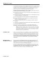
DATA CONNECTIVITY FOR
A TYPICAL BUSINESS
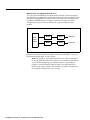
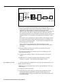
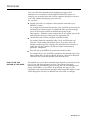
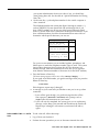
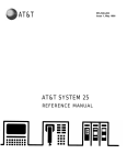
Figure 1-2 shows how one department of a typical business makes use of the
data capabilities the MERLIN II system provides. At the brokerage firm of
Bye, Loew, and Zelli, the staff of the commodities group use two types of
digital workstations connected to the MERLIN II system. This arrangement
allows them to:
• Communicate with others in the firm via electronic mail.
• Work with files from the firm’s minicomputer at their own terminals.
• Access the minicomputer or their own terminals from outside the office.
The consultants, research assistant and group secretary use a data hunt group
to access the firm’s minicomputer. The consultants and the research assistant
use an outgoing modem pool to place calls to the Porknbeans Line and other
subscription information services for commodities traders.
Data Communications with the MERLIN II System 1-7
FIGURE 1-2 Data connectivity for the commodities group at Bye, Loew, and Zelli.
Modem pool for
outgoing calls
Data hunt group
for in - house computer
MPDM
unit
Mini
computer
Control
MPDM
Data hunt group
for modem pool
MPDM
7406 with
FINANCIAL
CONSULTANT
GROUP SECRETARY
7406 with
PT 51OD
FINANCIAL
CONSULTANT
1-8 Data Communications with the MERLIN II System
Data
Data
Planning Overview
You can set up your MERLIN II system to provide:
• Simultaneous voice and data, voice only, or data only communications at
digital and analog workstations
• Local host computer access
• Modem pools for incoming and outgoing data calls
• Data hunt groups for local host computer access and outgoing modem
pools
The planning required to integrate data communications into your system
includes: ●
Making sure you have (or have ordered) the components needed for the
data options you want
●
Reserving the appropriate station lacks on analog, digital, or basic
telephone modules to connect the components to the MERLIN II system
control unit
●
Reserving the appropriate outside lines for modem pools on dedicated
lines
●
Making sure you have enough AC power outlets (one for each modem or
data module if you use stand-alone mountings, fewer if you use multiple
mountings)
The Planning Forms
As you plan data options, you record your decisions on the Master Planning
Form and the appropriate forms for the particular data options you select.
The Master Planning Form is provided in both. the MERLIN 11 System Planning
Guide and the MERLIN 11 System Manual. You may record information about
data options on:
• The Data Hunt Group Form and Incoming Modem Pool Form provided
with this guide
• Various forms provided with your MERLIN System Manual such as the
Call Restriction and AIlowed Lists Forms and the System Speed Dial Form
You use the Master Planning Form to reserve the jacks needed to connect
both voice and data components to your control unit. To insure that you’ll
have a fully integrated voice and data communications system, this section of
the guide shows how to fill out the Master Planning Form for all the stations
in your system, not just those with data capability.
Planning Overview 2-1
How to Use this Section of the Guide
This section provides:
• General information to help you decide how your system should operate
• Boxed instructions for recording your decisions on planning forms
How you use this section depends on whether you’re planning data options
for a new MERLIN II system or for a system that has already been
administered.
IF YOU’RE FILLING OUT
FORMS FOR A NEW
SYSTEM
If you’re planning data options for a system that hasn’t been administered
yet, you need photocopies of the MERLIN II system planning forms. Make
copies of the Data Hunt Group Form and the Incoming Modem Pool Form
provided at the end of this section.
If you don’t have copies of the forms provided in either the MERLIN II System
Planning Guide or Section 2 of the MERLIN II System Installation and
Administration Manual, remove the originals and copy them. Make sure to
copy both sides of all two-sided forms and return the originals to their proper
place. You won’t need all these forms for recording data options, but you’ll
probably use them when you plan voice features for your system.
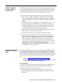
Read the explanations in this section of the guide, then follow the boxed
instructions to record information on data options on your Master Planning
Form and other forms. When you’ve finished, you can go to your MERLIN II
System Planning Guide or MERLIN II System Manual to finish planning your
MERLIN II system.
IF YOU'RE UPDATING THE
FORMS FOR A RUNNING
SYSTEM
If you’re adding data capability tO a MERLIN II system that has already been
administered, get the existing forms for your system. Make copies of the
Data Hunt Group Form and the Incoming Modem Pool Form provided at the
end of this section.
Follow the boxed instructions under “Identifying Line and Station Modules”
to identify the modules being added to your system. To select data options,
follow the boxed instructions in:
Reserving Station Jacks for Voice and Data Workstations"
• "Reserving Jacks for Computer Access and Modem Pools"
• "Planning Data Hunt Groups"
When you’ve finished planning data options, go on to Section 3 of this guide,
"Connecting Hardware and Setting Options."
2-2 Planning Overview
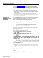
Components of the MERLIN II System
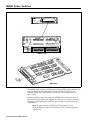
FIGURE 2-1 Basic MERLIN II System Components.
Control unit
Power
Power failure
telephone
Line jacks
Station jacks
1
Analog station
(voice terminal)
!
Digital station
(voice terminal)
Basic
telephone
To network interface
If you aren’t familiar with the MERLIN II system, study Figure 2-1. Then
read the definitions of basic terms that follow,
• Control Unit: When the system is installed, modules containing a power
source; a processor; and jack connection for outside lines, MERLIN II
system telephones, and other devices are mounted on a carrier. The
resulting assembly is called the control unit.
• Line Jacks: The line jacks on the control unit modules connect outside lines
or optional paging or music equipment to the system. The system can
accommodate up to 56 outside lines.
• Voice Terminal: A voice terminal is a programmable MERLIN II system
telephone.
Components of the MERLIN II System 2-3
• Station: A station is the endpoint of any connection within the MERLIN II
system. It can be a voice terminal, a basic telephone, a General Purpose
Adapter (GPA), a modem, a data terminal, or a personal computer.
– Analog Station: An analog station is one with an analog voice terminal,
data device, and/or accessory. Analog voice terminals such as the 10button, 22-button, and 34-button models can be directly connected
only to analog station jacks on the control unit.
—
Digital Station: A digital station is one with a digital voice terminal or
data device, Digital stations such as the 7406 voice terminal and the
Personal Terminal (PT) 510D can be directly connected only to digital
station jacks on the control unit.
—
Basic Telephone: A basic telephone is a standard Touch-Tone or rotary
telephone. Basic telephones in regular use are connected to basic
telephone jacks on the control unit. Basic telephones used exclusively
as Power Failure Telephones are connected to power failure jacks on
line modules on the control unit.
• Station Jacks: The station jacks are those jacks on the modules in the
control unit that connect stations to the system. The system can
accommodate up to 72 responding stations.
2-4 Components of the MERLIN II System
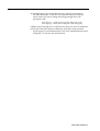
Identifying Line and Station Modules
During this first phase of planning you’ll be deciding how you want voice
and data components connected to jacks on the MERLIN II system control
unit and recording your decisions on the. Master Planning Form.
The jacks on the control unit modules provide points of connection for the
system’s outside lines and stations.
The system’s outside telephone lines connect to line jacks, as do
loudspeaker paging equipment and the music source for Music-on-Hold,
if your system has these options.
Data devices, voice terminals, and basic telephones connect to station
jacks.
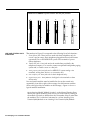
TYPES OF MODULES
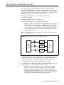
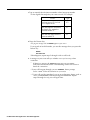
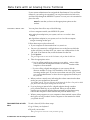
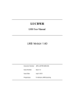
The first step in planning your system is to decide what line and station
modules will appear in each slot in your control unit. The various types of
modules are described below and shown in Figure 2-2. An explanation of
how the MERLIN II system assigns numbers to lines and station jacks on
modules is found under “Automatic Numbering of Jacks on Line and Station
Modules. ”
The 4-Line/8-Analog Voice Terminal (408) Module has four line jacks near
the top of the module and eight station jacks on the bottom portion of the
module.
The 8-Analog Voice Terminal (008) Module has eight station jacks at the
bottom.
The 4-Line with Touch-Tone Receivers (400 w/HTR) and &Line (800)
modules have line jacks on their top portions.
The 12-Basic Telephone (012) Module has 12 station jacks— four at the
top and eight at the bottom.
The digital Station (O08D) Module has four station jacks at the top— and
four near the bottom.
There is a power failure jack for every four outside line jacks on a module.
Identifying Line and Station Modules 2-5
FIGURE 2-2 The MERLIN II system modules and their jack positions.
400 W/TTR
408
012
800
— 1
—
—
2
008D
1
—
2
—
2
—
1
3
4
4
J
LINE AND STATION JACK
FUNCTIONS
The numbers in Figure 2-2 correspond to the following list of jack functions:
1
Power failure jacks: These jacks are used with basic telephones only. In
case of a power outage, basic telephones plugged into these jacks become
operational. Do not use MERLIN II system voice terminals as power
failure telephones.
2
Outside line jacks: These jacks are for the outside lines provided by the
telephone company. YOU can also connect an optional-loudspeaker paging
system and/or a music source to a line jack.
3
Analog station jacks: These jacks are for MERLIN II system analog voice
terminals, analog data devices, or accessories only.
4
Basic telephone jacks: These jacks are for basic telephones only.
5
Digital Station jacks: These jacks are for digital voice terminals or data
devices only.
Line and station modules must be installed in slots on the control unit
sequentially, from left to right, with no empty slots left between modules.
(Slots to the right of the last module can be left empty.) Figure 2-1 shows a
typical module installation.
On the drawing labeled "Module Location” on the Master Planning Form,
identify the type of module in each slot on your control unit by writing in
the module type (such as 008D) above the slot number. Keep in mind that
the module in slot 1 of the basic unit must be a 4-Line/8-Analog Voice
Terminal (408) Module or an 8-Analog Voice Terminal (008) Module.
2-6 Identifying Line and Station Modules
AUTOMATIC NUMBERING
OF JACKSON LINE AND
STATION MODULES
When you turn the power on at the power supply module, the system scans
the modules from left to right and from bottom to top. As it does so, it
identifies the type of module installed in each slot in the control unit.
Beginning with line 01 and station 01, the system numbers the line jacks and
station jacks from the bottom to the top of each module, and from left to right
Labels for the control unit jacks are provided with the system. The station
jack labels are numbered 01 through 88. The line jack labels are numbered 01
through 56. Once the control unit is assembled and these labels affixed to the
modules, you can teIl at a glance which jacks are for outside lines and which
NOTE: The administrator can assign different numbers to lines and
stations. See “Flexible Numbering” in the MERLIN II 5ystem
If you later replace a module with one of a different type, the system
continues to operate as though the original module were still in place. You
must perform a speciaI administration procedure to change your system’s line
and/or station numbers and relabel the jacks accordingly. Refer to Section 3
ldentifying Line and Station Modules 2-7
Reserving Line Jacks
You use the Master Planning Form to reserve line jacks for:
• Outside lines
• Music-on-Hold, if you use this feature
• Loudspeaker Page, if you use this feature
The “Line Jacks” section of the Master Planning Form has six columns. The
first and fourth columns, headed “Line Jack, ” list all the possible line jack
numbers (01 through 56). In the columns headed “Telephone No. or
Equipment, ” you identify the outside telephone line or piece of equipment
connected to each line jack on your control unit.
OUTSIDE LINE
CONNECTIONS
To simplify system administration, you should plan to connect your outside
telephone lines to an unbroken sequence of line jacks, beginning with line
jack 01. You should also plan to group your lines together according to type.
Reserve the line jacks at the beginning of the sequence for your local lines,
and reserve jacks later in the sequence for special-purpose lines such as
WATS and foreign exchange (FX) lines.
If you know the telephone numbers for your system’s outside lines, do the
following:
1 Match each outside line with a line jack on the control unit.
2 Under "Telephone No. or Equipment," enter the telephone number for
each outside line next to the number for its line jack.
If you don’t yet know the telephone numbers for your system’s outside
lines, do the following:
1 Enter the type of line (local, WATS, etc.) you plan to connect to each
line jack next to the number for that line jack.
2 When you find out the telephone numbers for your outside lines, enter
them next to the appropriate line jack numbers.
EQUIPMENT
CONNECTIONS
Now that you’ve reserved enough line jacks on the control unit for your
outside telephone lines, you can reserve a line jack for any optional
equipment that requires one. If you use the Music-on-Hold feature, you need
to reserve a line jack for a music source such as a radio, tape player, or stereo
system. If your business has a loudspeaker paging system, you need to
reserve a line jack for the paging equipment.
To make it easy to add outside lines in the future, use the last line jack(s) on
your control unit for the Music-on-Hold and/or Loudspeaker Page connection.
If your system has Music-on-Hold, write “music source” on the line next to
the number of the line jack used to connect the music source to the system.
If your system has loudspeaker paging, write "paging system" next to the
number of the line jack used to connect paging equipment to the system.
2-8 Reserving Line Jacks
Reserving Statio n Jacks for Voice and Data Workstations
You must reserve station jacks on the Master Planning Form for:
• Analog voice terminals
• Basic telephones
• Digital workstations used for voice and data or for data communications
only
NOTE: You also reserve station jacks for any devices such as data
modules, modems, and BTMIs that are used for local host computer
access and outgoing and incoming modem pools. “Reserving Jacks
for Computer Access and Modem Pools, ” which follows, explains
how to plan for these data options.
The"Station Jacks" section of the Master Planning Form lists the numbers (01
through 88] for all possible station jacks on the control unit. You record the
jack type for each station jack on the modules in your control unit: "A" for
analog, "D" for digital, or "B” for basic telephone. Next you identify by
person, location (such as "mail room"), or function (such as "incoming
modem pool") the station connected to each station jack on your control unit.
STATION JACK TYPE
The first step in filling out the "Station Jacks" section of the Master Planning
Form is to identify the type of jack that each station number represents. The
Module Location drawing shows the order in which modules containing
analog, digital, and/or basic telephone station jacks are installed in your
control unit. Keep in mind that station jacks on these modules are numbered
from the bottom to the top of each module and from left to right across the
control unit.
You’ll note that the first eight jacks are already identified with an "A" on the
form. This is because the module in slot 1 must be a 4-Line/8-Analog Voice
Terminal (408) module or an 8-Analog Voice Terminal (008) Module.
In the "Jack Type" column, record the jack type for each station jack o
your control unit: "A" for analog, "D" for digital, or "B" for basic
telephone.
Reserving Station Jacks for Voice and Data Workstations
2-9
Analog Stations
Filling out the "Station Jacks" section of the Master Planning Form for analog
stations basically consists of assigning intercom numbers to stations by
matching station jack numbers with people, locations, or functions. But the
following analog stations require special consideration:
• Attendant stations
• Stations with the Simultaneous Voice and Data feature
• Stations with the Voice Announcement to Busy Voice Terminal feature
ATTENDANT STATIONS
Attendant stations are voice terminals that are specially administered for call
handling and other duties of telephone attendants such as receptionists.
Only analog voice terminals can be attendant stations.
Station 10
In every system, the station connected to station jack number 01 is the
primary attendant position and the central administration point. The voice
terminal connected to station jack 01 is called the administrator/attendant
console and is assigned intercom number 10.
On the row for station jack 01 on the Master Planning Form, identify the
primary attendant station as follows:
1 In the "Station Jack" column, write "Att" next to the preprinted “01”
identify this as an attendant station.
to
2 In the "Person, Location, or Function" column, write in the name or
location of the primary attendant.
Other Attendant Stations
Certain stations in addition to station 01 can serve as attendant positions.
They are the stations connected to every fourth analog station jack after
number 01 on the control unit. For example, if the first 16 station jacks on
your control unit are on analog station modules, the possible attendant
stations (in addition to station 01) are those connected to jacks 5, 9, and 13.
Your system can have as many as eight attendant stations, depending on the
number of analog station modules you have.
Identify other possible attendant stations in your system as follows:
1 In the "Station Jack" column, write "Att" next to the number for every
fourth analog station jack after station jack number 01.
2 Fill in the "Person, Location, or Function" column for the stations
you know will be attendant stations when your system is up and
running.
3 Remove the "Att" designation from those station jacks that you won’t
use as attendant stations.
2-10 Reserving Line Jacks
STATION JACK PAIRS
Among the many optional features you can choose for one or more stations in
your system are the following:
●
Voice Announcement to Busy Voice Terminal
A person whose voice terminal has this feature can hear an announcement
through the speaker even though he or she is on a call. To provide this
feature, you assign the voice terminal two station jacks, called a voice/voice
pair, as explained below. (Digital 7406 voice terminals can’t use this
feature, since they don’t receive voice announcements over their
speakers.)
●
Simultaneous Voice and Data
A person whose station is administered for this feature can conduct voice
and data calls at the same time. To provide this feature, you assign an
analog voice terminal two station jacks, called a voice/data pair, as
explained below. (Digital stations don’t need a second jack to provide
simultaneous voice and data capability,)
An analog station with one of these options requires two consecutive analog
station jacks on the control unit. The jacks are an odd-numbered analog
station jack and the next higher (even-numbered) analog station jack. This
requires special wiring. (See Section 3 of this guide, " Connecting Hardware
and Setting Options.")
NOTE: You can assign either of these options to any of the analog
stations in your system, but you cannot assign both options to the
same station.
Voice/Voice Pairs
The first (odd-numbered) station jack in the pair provides the analog station’s
intercom number. Calls can’t be placed to the intercom number associated
with the even-numbered jack.
To reserve pairs of jacks for analog stations that will have the Voice
Announcement to Busy Voice Terminal feature, do the following:
1 In the "Station Jack" column, draw a box around the pair of jack
numbers that you plan to assign to each analog station with this
feature.
NOTE: You can assign this feature to an attendant position.
2 In the "Person, Location, or Function" column, next to the first (odd)
number of each boxed pair, identify the station by person or location.
3 In the "Person, Location, or Function" column, next to the second
(even) number of each boxed pair, write “VVP” (for voice/voice pair).
Reserving Station Jacks for Voice and Data Workstations 2-11
Voice/Data Pairs
The first (odd-numbered) station jack of the pair assigned to an analog station
equipped for Simultaneous Voice and Data provides the intercom number for
that station. Calls can’t be placed to the intercom number associated with the
even-numbered jack.
Assign pairs of jacks to analog stations that will have the Simultaneous
Voice and Data feature as follows:
1 In the "Station Jack" column, draw a box around each pair of numbers
representing analog station jacks that you plan to assign to these
stations.
NOTE: YoU can assign this option to an attendant station.
2 In the "Person, Location, or Function" column, next to the first (odd)
number in each boxed pair, identify the station by person or location.
3 In the "Person, Location, or Function" column, next to the second
(even) number in each boxed pair, write “VDP" for (voice/data pair).
REMAINING ANALOG
STATIONS
Now that you’ve reserved station jacks on the control unit for stations that
need special consideration, you can reserve station jacks on 4-Line/8-Analog
Voice Terminal (408) Modules or on 8-Analog Voice Terminal (008) Modules
for any other analog stations in your system.
To reserve station jacks for the remaining analog stations, do the
following:
1 In the "Person, Location, or Function" column, identify each station in
your system by person or location.
Note: You might not have an analog station for each analog jack on
your control unit. If so, just leave the spaces blank next to those
station numbers on the Master Planning form. You can't use the
station number associated with an analog staion jack for a digital
station or basic telephone.
2-12 Reserving Line Jacks
Basic Telephones
If you have any basic telephones, reserve jacks for them on a 12-Basic
Telephone (012) Module.
To reserve station jacks for basic telephones, do the following:
1
Locate station numbers with "B" in the "Jack Type" column.
2
In the "Person, Location, or Function” column, identify each basic
telephone in your system by person or location.
Digital Workstations
You reserve jacks on 8-Digital Station (008D) Modules for digital workstations
such as the:
• 7406 voice terminal with data stand for voice and data communications
• PT 510D for voice and data communications
• Modular Processor Data Module (MPDM) connected to a data terminal or
personal computer for data communications only
NOTE: The 7406 voice terminal with data stand requires a local power
supply. See Section 3 of this guide, "Connecting Hardware and
Setting Options," for details.
To reserve station jacks for digital workstations, do the following:
1 Locate station numbers with "D" in the "Jack Type" column.
2 In the "Person, Location, or Function" column, identify each digital
station in your system by person, location, or function. Add the
notation "DO" (data only) for any digital stations used for data
communications only.
NOTE: The MERLIN II System Installation and Administration Manual
describes how to plan Flexible Numbering of lines and stations and how to
assign alphanumeric labels. If you are considering using these features,
see Section 2, "Planning the System, " for instructions on completing the
Master Planning Form and completing the Flexible Numbering form.
Reserving Station Jacks for Voice and Data Workstations 2-13
Reserving Jacks for Computer Access and Modem Pools
If you want your system to have local host computer access or incoming or
outgoing modem pools, you need to reserve station jacks for these data
options.
Local Host Computer Access
Local host computer access is a method of connecting digital station jacks on
the MERLIN II system control unit to the EIA RS-232-C ports of an on-site
computer. This connection is made through Modular Processor Data Modules
(MPDMs). MPDMs convert the digital data signals sent through the control
unit to EIA RS-232-C data signals that the computer can receive, and vice
versa.
Users access the computer by placing a data call to a station jack that you’ve
designated for local host computer access. If you have as many computer
access station jacks as users or if people need to be sure of having access to
the computer at any time, you can give each person a different station
number to call. However, if many people share a computer, you may prefer
to assign some or all of the station jacks to a data hunt group with a single
access number (see “Planning Data Hunt Groups” ).
To reserve jacks on digital station modules at the control unit for local host
computer access, follow these steps:
1 Determine the total number of station jacks you’re going to use for
access to a bcal host computer. Keep in mind that you need an
MPDM for each jack.
2 On the "Station Jacks" section of the Master Planning Form, locate that
nurnber of available digital station jacks.
3 In the "Person, Location, or Function" column for each jack number,
write "LHCA - MPDM" (for local host computer access using a Modular Processor Data Module).
2-14 Reserving Jacks for Computer Access and Modem Pools
2-14 Reserving Jacks for Computer Access and Modem Pools
Modem Pools
Modem pools are groups of modems and associated equipment used to
convert digital data signals to analog data signals or vice versa. Signals must
be converted in this way for:
• Outside calls to and from digital stations
• Internal calls between digital and analog endpoints
Putting modems in pools makes it easier for users to share a limited number
of modems. Each modem pool is used exclusively for either incoming or
outgoing calls.
Each modem configuration in a modem pool consists of:
A Modular Trunk Data Module (MTDM) with an RS-232-C Interface.
A 2212C or other compatible modem.
Where required, a Basic Telephone and Modem Interface (BTMI). BTMIs
are required if the modem connects to a jack on an analog module rather
than to a jack on a basic telephone module or to a dedicated outside line.
Modem Pools Using MERLIN II System Lines
Typically, modem pools handle calls that are placed and received through the
MERLIN II system control unit. The lines used for these calls maybe
assigned only to members of a modem pool or they may be shared with other
stations in the MERLIN II system. As Figure 2-3 shows, these configuration
require one station jack on a digital station module and one station jack on
either an analog station module or a basic telephone module.
FIGURE 2-3 Modem pool for calls through the MERLIN II system control unit.
Basic
telephone
module
Digital
station
module
I
Reserving Jacks for Computer Access and Modem Pools 2-15
Modem Pools on Dedicated Outside Lines
You can bypass the MERLIN II system control unit and connect an outside
line directly to a modem for use with that modem only. Because the line isn’t
connected to the MERLIN II system control unit, calls aren’t recorded by the
Call Report (SMDR) feature. As Figure 2-4 shows, this type of modem
configuration requires only one station jack, a jack on a digital station
module.
FIGURE 2-4 Modem pools for calls on dedicated outside lines.
1
Digital
3
2
MTDM
station
module
Outside line
Modem
/
MTDM
Modem
Outside line
Instructions for planning different types of modem pools follow. Carry out
the instructions that apply to your system.
NOTE: The people in your business need to know what modem pools
to use for particular data calls and how to access those pools. When
you’ve finished planning your modem pools, it’s a good idea to
prepare a user information sheet on them. The sheet should list
modem pool access numbers and describe any special considerations
for using the modem pools you’ve set up.
2-16 Reserving Jacks for Computer Access and Modem Pools
OUTGOING MODEM
POOLS ON MERLIN II
SYSTEM LINES
You need to pair digital station jacks with analog or basic telephone jacks to
create modem configurations for outgoing calls on MERLIN II system lines.
You can group into modem pools any modem configurations for outgoing
calls that have the same station jack type, modem type, and speed.
TO reserve jacks for outgoing modem pool pairs, perform these steps:
1 In the "Person, Location, or Function" column on the Master Planning
Form, write "OMP #1 - MTDM" (for outgoing modem pool number 1,
using an MTDM) next to an available station jack number marked "D"
(digital).
2 Locate a jack marked "A" (analog) or "B" (basic telephone) to pair with
the digital station jack. Write "OMP #1" in the "Person, Location, or
Function" column if the jack is a basic telephone jack or write "OMP
#1 - BTMI" in the "Person, Location, or Function" column if the jack is
for an analog telephone jack and a BTMI is required.
3 Repeat steps 1 and 2 for each modem configuration that has the same
modern type, station jack type, and speed.
4
Repeat steps 1 through 3 for each group of modem pool pairs.
5 Record the station number of each analog or basic telephone jack in an
outgoing modern configuration on a separate Station Configuration
Form. The Station Configuration Forms are found in the MERLIN II
System Installation and Administration Manual. Cross out the words
"Voice Terminal" and write "Station" above the crossed-out words.
On the spaces provided for identifying button assignments, record the
lines or line pools to be assigned to the outgoing modem
configurations. Section 4, "Administering Data Options," explains how
to assign lines to these station jacks.
INCOMING MODEM POOLS
ON MERLIN II SYSTEM
LINES
You need to pair digital station jacks with analog or basic telephone jacks to
create modem configurations for incoming calls on MERLIN II system lines.
You can group into modem pools any modem configurations for incoming
calls that have the same station jack type, modem type, and speed and record
this information on the Incoming Modem Pool Form and Master Planning
Form.
NOTE: See "Modem Pools on Dedicated Outside Lines" for
information on filling out the Incoming Modem Pool Form for modem
pools that don’t use MERLIN II system lines.
Line Assignments
You need to assign lines or line pools to the analog or basic telephone jacks
for modem pool members so that data calls can come into these jacks.
Keep these points in mind as you assign lines:
• It’s best not to assign the same lines or line pools to voice terminals and
to incoming modern pools because the moderns will answer voice calls
as data calls.
Reserving Jacks for Computer Access and Modem Pools
2-17
• Lines and line pools assigned to modem pools can also be assigned to
other stations in the system. However, the line or line pool should be set
to ring only at the jack for the modern pool member.
• If you want to permit simultaneous incoming data calls to a single
telephone number, you can have your local telephone company supply a
telephone line hunt group. With this arrangement, one number applies to
several lines that you can assign to the members of the incoming modem
pool.
Group Call Distribution
For efficient call handling, you may want to assign the same lines or line
pools to all members of a modem pool, then assign the Group Call
Distribution feature to the modem pool members. Whenever a call comes in
on one of the lines assigned to a modem pool with Group Call Distribution,
the system scans the analog or basic telephone jacks for the members of the
modem pool and connects the call to the first available station jack.
To reserve jacks for incoming modem pool pairs, perform these steps:
1 If you'll have more than two incoming modem pools,. make the
required number of copies of the Incoming Modem Pool Form.
2 In the "Person, Location, or Function" column on the Master Planning
Form, write "IMP #1 - MTDM" (for incoming modem pool number 1,
using an MTDM) next to an available station jack number marked "D"
(digital).
3 Locate a jack marked "A" (analog) or "B" (basic telephone) to pair with
the digital station jack. Write "IMP # l" in the "Person, Location, or
Function" column for a basic jack number or write "IMP # 1 - BTMI" in
the "Person, Location, or Function" column for an analog telephone
jack number to indicate that a BTMI is required.
4 Repeat steps 2 and 3 for each modem configuration that has the same
modem type, station jack type, and speed.
5 Repeat steps 2 through 4 for each group of modem pool pairs.
6 Enter the number of the first modem pool (Modem Pool) on the
form. Check the appropriate box or fill in the blank to record modem
type, jack type and speed to indicate whether the modem pool
uses the Group Distribution feature.
7 On the Master Planning Form, locate the pairs of station jacks that you
plan to assign to Modem Pool 1. On the Incoming Modem Pool Form
record each pair of station numbers on a separate line in the column
headed "Station Jack Numbers."
8 In the column headed "Lines/Line Pools," record the numbers of the
outside lines or line pools that should be assigned to the analog or
basic telephone jack in each pair of station jacks.
9 Repeat steps 6 through 8 for each incoming modem pool. Number
your additional pools in turn with 2, 3, etc.
2-18 Resewing Jacks for Computer Access and Modem Pools
MODEM POOLS ON
DEDICATED OUTSIDE
LINES
You may want to set up incoming or outgoing modem pools on dedicated
outside lines if:
You have a large volume of data communications and want to keep the
outside lines for your MERLIN II system available for voice calls.
You use specialized outside lines for data communications.
You don’t have sufficient analog or basic telephone jacks for all the
modem pools you want to set up.
Identifying Station Jacks on the Master Planning Form
The first step in planning for modem pools on dedicated outside lines is to
enter the appropriate information on the Master Planning Form.
Follow these steps to reserve digital station jacks for modem pools on
dedicated outside lines:
1 In the "Person, Location, or Function" column on the Master Planning
Form, locate an available jack marked "D" (digital). Next to the jack
number, write "IMPP-DL-M" (for incoming modem pool pair on a
dedicated line, using an MTDM) or "OMPP-DL-MTDM" (for outgoing
modem pool pair on a dedicated line, using an MTDM).
2 Repeat step 1 for each modem configuration on a dedicated outside
line.
Completing the Incoming Modem Pool Form
If you have incoming modem pools on dedicated lines, you need to enter
information about those pools on the Incoming Modem Pool Form.
Follow these steps to complete the Incoming Modem Pool Form:
1 Determine the total number of incoming modem pools on dedicated
outside lines that you have. Keep in mind that only modems of the
same type and speed can make up a modem pool.
2 Record the number of the modem pool, the modem type, and the
speed in the appropriate places. Don't check a jack type and check
"No" to show that the modem pool doesn't have the Group Call
Distribution feature.
3 Referring to the Master Planning Form, record the station numbers of
all digital jacks marked "IMPP-DL-MTDM" that have modem
configuartions with the modem type and speed marked. Write the jack
numbers on the consecutive lines.
4 On the crresponding line under "Lines/Line Pools," write the number
of the outside line connected to the modem.
5 Repeat step 2 through 4 for each incoming modem pool on a
dedicated line in your system.
Reserving Jacks for Computer Access and Modem Pools 2-19
Planning Data Hunt Groups
Data hunt groups are groups of digital station jacks with a single access
number. These jacks provide access, through a data module, to:
• A local host computer
• An outgoing modem pool
When someone dials the number for the data hunt group, the MERLIN II
system checks the jacks in round-robin order and directs the call to the first
available jack in the group. It generates a busy message if all the jacks in the
group are in use.
CONSIDERATIONS FOR
SETTING UP DATA HUNT
GROUPS
Keep these points in mind as vou plan data hunt groups:
A
• The modem configurations in outgoing modem pools have to be
interchangeable. They must have the same modem type and speed
setting, since callers won’t know which station jack they are accessing
when they dial the data hunt group number for the outgoing modem
pool.
• You can set up data hunt groups for outgoing modem pools on dedicated
outside lines. But you can't place outgoing modem configurations that use
dedicated outside lines in the same data hunt group as modem
configurations that use standard MERLIN II system lines.
TO reserve jacks on digital station modules at the control unit for data hunt
groups, follow these steps:
1 On the Master Planning Form, identify each station jack that you’re
assigning to a data hunt group. Write "DHG" (for data hunt group) in
the "Person, Location, or Function" column to the right of the existing
entry. (The completed entry for a station jack in a data hunt group for
local host computer access, for example, would be
"LHCA-MPDM-DHG.")
2 The default code numbers for datta hunt groups are listed on the Data
Hunt Group Form as *870 through *875. Those are the numbers users
dial to reach the local host computer or modem pool, unless different
numbers are assigned through Flexible Numbering. Follow these steps
to identify the station jacks in each data hunt group, beginning with
the first group:
a Complete the top of the column by checking the appropriate boxes
for a local host curnputer or outgoing modem pool. If the data hunt
group is for an outgoing modem pool, select the modem type and
jack type. Record the data speed.
b
Refer to the Master Planning Form and write in the number of each
station jack that you want to assign to the data hunt group
(maximum of 16). Record each jack number on a separate line.
NOTE: If you're assigning the station jacks for modem pools on
dedicated outside lines to a data hunt group, record the telephone
number of the line next to the station jack number.
2-20 Planning Data Hunt Groups
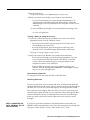
Master Planning Form
Line
Jack
Default
Line
No.
01
Line
Jack
Default
Line
No.
801
29
829
02
802
30
830
03
803
31
831
04
804
32
832
05
805
33
833
06
806
34
834
07
807
35
835
08
808
36
836
09
809
37
837
10
810
38
838
11
811
39
839
12
812
40
840
13
813
41
841
14
814
42
842
15
815
43
843
16
816
44
844
17
817
45
845
18
818
46
846
19
819
47
847
20
820
48
848
21
821
49
849
22
822
50
850
23
24
823
51
851
824
52
852
25
825
53
853
26
826
54
854
27
827
55
855
28
828
56
856
Telephone No. or Equipment
Telephone No. or Equipment
*Flexible numbering applies:
❑ Yes
❑ No
Master Planning Form 2-21
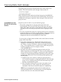
Master Planning Form
Module Location
Expansion unit
Basic unit
I
I
I
Power
supply
slot
2-22 Master Planning Form
I
I
Power
Power
slot
identification:
1
0
1
2
3
4
5
Power
supply
slot
6
7
8
9
10 11
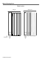
Master Planning Form
Station Jacks
Jack
Default
Station Type
Icom
Jack
(A,D,B) No.
01
A
10
02
A
11
03
A
12
04
A
13
05
A
14
06
A
15
07
A
16
08
A
17
09
18
10
19
11
20
12
21
13
22
14
23
15
24
16
25
17
26
18
27
19
28
20
29
21
30
22
31
23
32
24
33
25
34
26
35
27
36
Person,
Label
Location,
or Function
Face
I
1
I
I
Jack
Default
Station Type
Icom
Jack
(A,D,B) No.
31
40
32
41
33
42
34
43
35
44
36
45
37
46
38
47
39
48
40
49
41
50
42
51
43
52
44
53
45
54
46
55
47
56
48
57
49
58
50
59
51
60
52
61
53
62
54
63
55
64
56
65
57
66
28
37
58
67
29
38
59
68
30
39
60
69
Person,
Label
Face
Location,
or Function
Flexible numbering applies:
❑ Y E S
❑
N O
●
Master Planning Form 2-23
Station Jacks (Continued)
Jack
Default
Station Type
Icom
(A,D,B) No.
Jack
Label
Face
Person,
Location,
or Function
Jack
Default
Station Type
Icom
Jack
(A,D,B) No.
61
700
75
714
62
701
76
715
63
702
77
716
64
703
78
717
65
704
79
718
66
705
80
719
67
706
81
720
68
707
82
721
69
708
83
722
70
709
84
723
71
710
724
72
711
85
86
73
712
87
726
74
713
88
727
2-24 Master Planning Form
725
Label
Face
Person,
Location,
or Function
Incoming Modem Pool Form
Modem Pool
❑ 2212C Modem ❑ Other (Model
❑ Analog Jack
❑ Basic Telephone Jack
❑ Yes
Pool members in Call Distribution group?
..
Speed
❑ No
L i n e s / L i n e
Station Jack Numbers
1
)
P o o l s
1
2
3
4
5
6
7
8
9
10
11
12
13
14
15
16
Modem Pool
❑ 2212C Modem ❑ Other (Model
❑ Analog Jack
❑ Basic Telephone Jack
Pool members in Call Distribution group?
❑ Yes
Station Jack Numbers
)
Speed
❑ No
Lines/Line Pools
1
2
3
4
5
6
7
8
9
10
11
12
13
14
15
16
Incoming Modem Pool Form 2-25
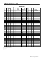
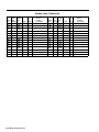
Data Hunt Group Form
*870
*871
*872
❑ Local Host Computer
❑ Local Host Computer
❑ Local Host Computer
❑ Outgoing Modem Pool
❑ Outgoing Modem Pool
❑ Outgoing Modem Pool
❑ 2212C ❑ Other (Model
❑ 2212C
❑ Other (Model
)
❑ Analog Jack ❑ Basic Tel. Jack
Speed
❑ 2212C ❑ Other (Model
)
❑ Analog Jack ❑ Basic Tel. Jack
❑ Analog Jack
S p e e d
1
2
3
4
5
6
7
8
9
10
11
12
13
14
15
16
Speed
1
2
3
4
5
6
7
8
9
1 0
1 1
1 2
1 3
1 4
1 5
1 6
1
2
3
4
5
6
7
8
9
1
1
1
1
1
1
1
0
1
2
3
4
5
6
* 873
❑ Local Host Computer
❑ Outgoing Modem Pool
❑ 2212C ❑ Other (Model
)
❑ Analog Jack ❑ Basic Tel. Jack
)
❑ Basic Tel. Jack
*874
❑ Local Host Computer
❑ Outgoing Modem Pool
❑ 2212C ❑ Other (Model
)
❑ Analog Jack ❑ Basic Tel. Jack
’875
❑
❑
❑
❑
Local Host Computer
Outgoing Modem Pool
2212C ❑ Other (Model
)
Analog Jack ❑ Basic Tel. Jack
Speed
1
2
3
4
5
6
7
8
9
1 0
1 1
1 2
1 3
1 4
1 5
1 6
1
2
3
4
5
6
7
8
9
1
1
1
1
1
1
1
1
2
3
4
5
6
7
8
9
0
1
2
3
4
5
6
1
1
1
1
1
1
1
0
1
2
3
4
5
6
Data Hunt Group Form 2-27
Installation Overview
DIGITAL STATION
CONNECTIVITY
The diagrams and descriptions below are typical hardware configurations for
a MERLIN II system with voice and data capability. They include:
A digital station equipped for simultaneous voice and data
communications
• A 7406 voice terminal with a data stand (Z703A), connected to a data
terminal
• A Personal Terminal (PT) 510D
A digital station equipped for data communications only
An analog station equipped for simultaneous voice and data
communications
Local host computer access
Modem pools for:
• Data calls from a digital data endpoint
• Data calls to a digital data endpoint
• Data calls on dedicated outside lines
This section gives general instructions for connecting Data Terminal
Equipment (DTE) and Data Communications Equipment (DCE) to the
MERLIN II control unit. It also discusses setting data options to ensure that
equipment throughout the system is compatible.
NOTE: Compatibility with the PC/PBX Connection and other data
products will be provided with the documentation for that equipment.
HOW TO USE THIS
SECTION
This. section of the guide provides guidelines for connecting data equipment
to a MERLIN II system. It is intended to supplement, not replace, the
documentation provided with the hardware. For detailed installation
information, consult the appropriate hardware manual.
BEFORE YOU BEGIN
The Master Planning Form shows the station jacks on the control unit that
should be used for each data hardware configuration in your system. Keep
the completed form handy for reference as you connect cords to jacks on
station modules.
This section of the guide assumes that all the required station modules have
been installed in your control unit. It also assumes that you have the
components and cables required to assemble and connect the data hardware
planned for your system. If you don’t have the equipment you need, contact
your equipment supplier or technical consultant.
ABOUT THE NUMBERED
DIAGRAMS
Many of the figures in this section illustrate data connectivity for the
MERLIN II system. These diagrams, along with the Master Planning Form,
the Data Hunt Group Form, and the Incoming Modem Pool Form, provide a
guide for connecting data communications hardware to other equipment and
to the control unit. The numbers in each connectivity diagram correspond to
those of the explanatory notes beneath the figure.
Installation Overview 3-1
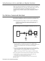
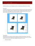
Simultaneous Voice and Data at Digital Stations
Digital voice and data workstations are connected to jacks on the 8-Digital
Station (008D) Modules in the control unit. These digital stations require only
one control unit jack connection for simultaneous voice and data
communications. Descriptions of typical digital configurations follow. For
information on the PC/PBX Connection, see the documentation for that
system.
The 7406 Voice Terminal with Data Stand
You can add data capability to a station with a digital voice terminal such as
the 7406 model by adding a data stand, local power, and a data terminal. The
connectivity diagram seen in Figure 3-1 shows a typical configuration.
NOTE: Be sure to set the switches as shown, under "Option Switches
on the Data Stand” before you connect the data stand to the
MERLIN II system.
FIGURE 3-1 A digital voice terminal equipped for simultaneous voice and
data.
7406 with
data stand
Digital
station
module
Local
power
1 The 4-pair modular cord running from the jack on the 8-Digital Station
(008D) Module in the control unit terminates at a standard telephone wall
jack at the voice terminal location. The maximum cable length is
1000 feet.
2 An ac power outlet provides required local power for the data stand. The
power cord runs from the ac outlet equipped with a power supply to the
standard telephone wall jack equipped with a power adapter.
NOTE: If you are using a KS-22911 L1 power supply, use a 400 B2 adapter.
3 The 4-pair modular cord runs from the local power adapter to the data stand.
4 Standard RS-232-C connectors and cable connect the data stand to the
data terminal. The maximum cable length is 50 feet.
For more information on installing the data stand, see the instructions
provided with it.
3-2 Simultaneous Voice and Data at Digital Stations
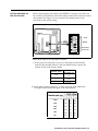
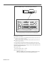
OPTION SWITCHES ON
THE DATA STAND
Before connecting the data stand to the MERLIN 11 system, you need to set
the switches on the bottom of the data stand to match those of the associated
data terminal. See Figure 3-2 for an example. The shaded portion of the
switch shows the switch setting.
FIGURE 3-2 Option switch settings on the 7406 data stand.
]
Parity
Speed
Disconnect
For Future Use
Enlarged view
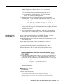
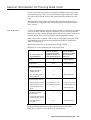
Follow these steps to set data option switches:
1 Set the parity switch (switch 1) for even or odd parity to match the data
terminal. (See the table below.) If the data terminal has no parity, the
position of the switch doesn’t matter.
Terminal parity
Even
On
Odd
Off
None
2
Set switch
1 to:
On or Off
Set the speed switches (switches 2, 3, and 4) as shown in the table below.
The speed should match the speed of the data terminal.
19200
Off
Off
Off
9600
Off
Off
On
4800
Off
On
Off
2400
Off
On
On
1200
On
Off
Off
300
On
Off
On
Simultaneous Voice and Data at Digital Stations 3-3
3 Set the disconnect sequence switch (switch 5) for escape or break.
Disconnect
4 Set option switch
sequence
Set switch 5 to
Escape, Escape
On
Break, Break, Break
Off
6 to off. (This switch reserved for future use).
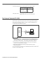
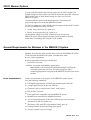
The Personal Terminal (PT) 510D
.
The PT 510D is a smart data terminal with a built-in programmable telephone.
The connectivity diagram in Figure 3-3 shows a typical configuration for a
PT 510D used in the MERLIN II system.
FIGURE 3-3 Connectivity for a PT 510D.
Digital
station
module
\
PT 510D
1 The 4-pair modular cord running from the jack on the 8-Digital Station
(008D) Module in the control unit terminates at a standard telephone wall
jack at the PT 510D location. The maximum cable length is 1000 feet.
2 The terminal line cord supplied with the M 510D connects the telephone
line jack on the terminal to the wall jack.
3 The ac power cord supplied with the PT 510D connects the ac power
outlet to the terminal.
For more installation information, see “Installation"in the User’s Guide: AT&’T
Personal Terminal Model 510D.
3-4 Simultaneous Voice and Data at Digital Stations
The Personal Terminal (PT) 510D
TERMINAL OPTIONS
The data communications options of the PT 510D can be set by Terminal
Setup A or B screens. You can also use options stored with the Directory
entry or sent by a host computer. Initially, Terminal Setup A and B have
factory-set values selected for the broadest applicability. Change these values,
where necessary, to match the data devices the users will call. Possible
speeds range from 300 to 19200 bits per second (bps).
You must standardize the basic settings for sending and receiving data for all
PT 510D in the system.
Other options, however, such as cursor and keyclick settings, are a matter of individual user preference.
The PT 510D user’s guide lists data communications options. Default settings
are marked. You can change any of these options as soon as the terminal is
powered up,
CALL HANDLING
FEATURES
Cover buttons (*40 and *50) cannot be programmed to any of the seven
buttons located on the touch sensitive screen below the dial pad on the
PT 510D. See the User’s Guide: 7406D and 7406B for specific call handling
features.
Simultaneous Voice and Data at Digital Stations 3-5
Digital Stations for Data Communications Only
Your Master Planning Form identifies any stations where personal computers
or data terrninals are connected to digital station jacks on the control unit
through Modular Processor Data Modules (MPDMs) for data communications
only. (The “Person, Location, or Function” column contains the phrase “DOMPDM.") An MPDM is a device that converts digital data signals sent
through the control unit to EI.A RS-232-C data signals that the computer can
receive and converts the computer’s sending signals back to digital data.
The following equipment is required for a digital station equipped for data
communications only:
• Modular Processor Data Module (MPDM) equipped with an RS-232-C
Interface
• Data terminal or computer
• Cables and connectors for connecting the components
NOTE: Before you activate these stations, set the switches on the
MPDM faceplate and the RS-232-C Interface (see "MPDM Option
Switches" under "Local Host Computer Access").
Figure 3-4 is a connectivity diagram that shows a typical configuration for data
communications only at a digital station.
FIGURE 3-4 A digital station equipped for data communications only.
Digital
station
module
Data
terminal
1 The 4-pair modular cord runs from a jack on the 8-Digital Station (008D)
Module at the control unit to a standard telephone wall jack at the data
terminal location. The maximum cord length for this connection is
1000 feet.
2 A 4-pair modular cord connects the MPDM to the wall jack.
3 Standard RS-232-C connectors and cable connect the MPDM to the data
terminal. The maximum cable length is 17 feet.
NOTE: If a number of MPDMs are to be connected at a common
location, you can put as many as eight in one multiple mounting
rather than installing each in a stand-alone mounting. A multiple
mounting reduces the number of ac power sockets needed to power
the MPDMs. See the documentation that came with your MPDM for
information on the multiple mounting connections.
3-6 Digital Stations for Data Communications Only
Simultaneous Voice and Data at Analog Stations
The Master Planning Form shows which analog stations should have
simultaneous voice and data capability. The numbers of the station jacks to
which each of these stations should be connected are boxed on the form.
Note that the jack pairs are consecutively numbered jacks on the same
4-Line/8-Analog Voice Terminal (408) Module or 8-Analog Voice Terminal
(008) Module. Each pair includes an odd-numbered jack and the jack with
the next higher even number, such as jacks 15 and 16.
The fundamental wiring scheme that joins the required pairs from each jack
into one 4-pair cord is indicated in the wiring diagram of Figure 3-5.
FIGURE 3-5 Wiring diagram: 4-pair connection from odd/even adjacent ports.
0 0 0
6 5 4 3 2
I
8 7 6 5 4 3 2 1
Odd
5 4
Even
At some point between the voice terminal and the odd/even jack pair, the
voice pair (5 and 4) from the even jack is joined with the other three pairs (4
to 8, 5 to 7) to make a complete 4-pair connection to the voice terminal.
To equip an analog station for simultaneous voice and data communication,
you need the following:
Analog voice terminal
General Purpose Adapter (GPA)
AT&T DATAPHONE® II 2212C modem or other compatible modem with
modular connection capability
Data terminal or computer
Cables and connectors for connecting the components
The connectivity diagram in Figure 3-6 shows a typical configuration for an
anaIog station with simulta.neous voice and data capability.
Simultaneous Voice and Data at Analog Stations 3-7
FIGURE 3-6 An analog station equipped for voice and data, using a jack field.
Apparatus bOX
with Z601A
adapter
General
Analog
station
, purpose
3
adapter
Modem
4
module
Data Terminal
1 If you have a jack field, the 4-pair modular cords running from the two
analog station jacks at the control unit terminate at Z601A adapters in an
apparatus box of the jack field. A wire pair is attached to the Z601A
adapter for the odd-numbered jack from the next higher (even-numbered)
jack to provide a data path in a single 4-pair cable. The 4-pair cable runs
from the apparatus box in the jack field to a standard wall-jack at the voice
terminal location. The maximum cord length for the connection is 1000
feet.
If you don’t have a jack field, the 4-pair modular cords running from the
two analog station jacks in the control unit terminate at a standard wall
jack at the voice terminal location. The maximum cord length from each
analog station jack is 1000 feet.
See the MERLIN II System Installation and Administration Manual for more
information on wiring methods that connect a second voice/data path to
one station.
2 The 4-pair modular cord that comes with the voice terminal connects the
voice terminal to the wall jack.
3 The connection from the voice terminal to the GPA is another 4-pair cord
that comes with the GPA.
4 A standard 2-pair modular connector cord runs between the GPA and the
modem.
5 Standard RS-232-C connectors and cable connect the modem to the data
terminal or computer. The maximum cable length is 50 feet.
EQUIPMENT OPTIONS
Set up the equipment for simultaneous voice and data communications at an
analog station as follows:
1 Administer the paired analog station jacks for the Simultaneous Voice and
Data feature.
2 Put the GPA in the Auto mode.
3 Consult the lists of option settings provided in the documentation for the.
modem and the data terminal or computer. Set the options to be
compatible with the settings on the data device with which the user will
be communicating.
3-8 Simultaneous Voice and Data at Analog Stations
Local Host Computer Access
Your Master Planning Form identifies the station jacks that should be
connected through MPDMs to a local host computer. (The "Person, Location,
or Function" column contains the phrase " LHCA-MPDM." ) Some or all of
the digital station jacks for the local host computer may be administered as a
data hunt group to provide a common access number.
Setting up local host computer access requires the following:
• Local host computer
• MPDMs equipped with RS-232-C Interfaces
• Cables and connectors for connecting the components
NOTE: Be sure to set the switches on the MPDM faceplates and the
RS-232-C Interfaces as described in "MPDM Option Switches" before
activating local host computer access. Some computers act as DCE
devices and may require an MTDM or special wiring. If an MTDM can
be used, the switch settings are the same as MPDM but you don’t
need to set auto answer.
Figure 3-7 shows the connectivity diagram for a typical local host computer
access configuration.
FIGURE 3-7 Connectivity for local host computer access.
1
2
3
MPDM
Digital
station
,
Local
MPDM
module
host
computer
MPDM
\
1 The 4-pair modular cord running from the jack on the 8-Digital Station
(008D) Module at the control unit terminates at a standard telephone wall
jack at the MPDM location. The maximum cable length is 1000 feet.
2 A 4-pair modular cord connects the MPDM to the wall jack.
3
Standard RS-232-C cables and connectors connect the MPDM to the local
host computer. The maximum cable length is 17 feet.
NOTE: If a number of MPDMs are to be connected at a common
location, you can put as many as eight in one multiple mounting
rather than having each in a stand-alone mounting. A multiple
mounting reduces the number of ac power sockets needed to power
the MPDMs. See the documentation that came with your MPDM for
information on the multiple mounting connections.
Local Host Computer Access 3-9
MPDM Option Switches
FIGURE 3-8 MPDM and RS-232-C interface option switch settings.
MPDW Facaplate
The MPDM faceplate has two Dual In-line Package (DIP) option switches, one
with 10 positions and the other with 12 position-as seen in Figure 3-8. In
addition, the RS-232-C Data Interface Circuit Pack has an 8-position DIP
option switch.
The documentation that came with your MPDMs discusses the function of
each switch setting. Follow the suggestions below to set switches unless the
computer or data terminal to which the data modules connect has different
requirements.
NOTE: All option switches on the RS-232-C Data Interface Circuit
Pack should be off unless the data device to be connected requires a
specific lead.
3-10 Local Host Computer Access
The following table lists the option settings for the MPDM faceplate.
Option
Comment
Data Rate
300 to 19200 bps
Select one speed, from 300 to 19200 bps, for data calls.
If the caller will use a modem pool, you must select the
same speed the modem uses.
TRBK
If ON, TRBK allows for three or more "breaks" to
disconnect a data call. If you choose this option, you
must also select ASYN, with the DISC and KYBD
options set to ON.
FDX
OFF selects full-duplex operation.
ASYN
OFF selects asynchronous operation and allows the
TRBK and DISC options to function.
Ext
Can be set to either ON or OFF.
DISC
If ON, DISC allows two seconds of a continuous
spacing signal (long break) to disconnect a keyboarddialed call. The KYBD option must also be ON.
KYBD
For data devices connected to the MPDM:
KYBD must be OFF if data devices are not to receive
call progress messages.
KYBD must be ON if data devices are to originate calls,
receive call progress messages, or disconnect calls
using the TRBK or DISC options.
OFF-PRTY
O/EV-l/OD
These option switches work together to determine the
parity for call progress messages:
Parity set to
PRTY
E/O
Odd
ON
1/OD
Even
ON
O/EV
One
l/OD
OFF
Zero
O/EV
OFF
The KYBD option must also be ON.
DMLL
Must be OFF.
MKBY
Must be OFF.
SIGLS
Must be OFF.
AANs
Must be ON, to enable the MPDM’s automatic answer
feature.
Local Host Computer Access 3-11
Modem Pools
Modem pools allow many digital endpoints to share a limited number of
modems for incoming and outgoing data calls. Your Master Planning Form,
Data Hunt Group Form, and Incoming Modem Poo1 Form list the control unit
jacks that should be assigned to each modem configuration that is a member
of a modem pool. The forms also provide other information about the
modem pools, such as whether a’ modem pool is incoming or outgoing and
what type of modem is used.
Each modem configuration in a modem pool includes the following:
• 2212C or other compatible modem
• Modular Trunk Data Module (MTDM) with RS-232-C Interface
An MTDM is a DTE device that seines as an interface between the control
unit and a modem. With the modem, it changes digital data signals from the
switching facilities to analog signals that can be transmitted over standard
telephone lines, and vice versa.
NOTE: If the modem is connected to an analog station jack rather
than to a basic telephone jack or a dedicated outside line, it requires a
Basic Telephone and Modem Interface (BTMI).
The diagrams that follow show typical configurations for modem pool
members connected to:
Basic telephone jacks at the control unit
Analog station jacks at the control unit
Dedicated outside lines (lines that aren’t connected to the MERLIN II
system control unit)
MODEM COMPATIBILITY
See "General Requirements for Modems in a MERLIN II System" for
information on using modems other than the 2212C modem in the MERLIN II
system.
MTDM AND MODEM
OPTION SETTINGS
Be sure to set the option switches on your equipment as described in "MTDM
Option Switches" and "2212C Modem Options" before activating modem
pools.
3-12 Modem Pools
Modem Configuration Connected to a Basic Telephone Jack
The connectivity diagram in Figure 3-9 shows modem pool members
connected to jacks on a 12-Basic Telephone (012) Module at the control unit.
This configuration doesn’t require a BTMI.
FIGURE 3-9 Modem pool members connected to basic telephone jack.
1
Basic
telephone
1
module
Digital
station
module
3
1
A 2-pair modular cord connects the modem to a jack on a 12-Basic
Telephone (012) Module at the control unit. The maximum cable length is
1000 feet.
2
Standard RS-232-C connectors and cable connect the MTDM to the
modem. The maximum cable length is 17 feet.
3
A 4-pair modular cord connects the MTDM to a jack on an 8-Digital
Station (008D) Module at the control unit. The maximum cable length is
1000 feet.
NOTE: If a number of MTDMs are to be connected at a common
location, you can put as many as eight in one multiple mounting
rather than installing each in a stand-alone mounting. A multiple
mounting reduces the number of ac power sockets needed to power
the MTDMs. See the documentation that came with your MTDM for
information on the multiple mounting connections.
Modem Pools 3-13
Modem Configuration Connected to an Analog Station Jack
Figure 3-10 is a connectivity diagram that shows a modem pool member
connected to an analog station jack. This configuration requires a BTMI.
FIGURE 3-10 A modem pool member with a BTMI connected to an analog
station jack.
1 A 4-pair modular cord connects the BTMI to a station jack on a
4-Line/8-Analog Voice Terminal (408) Module or an 8-Analog Voice
Terminal (008) Module at the control unit. The maximum cable length is
1000 feet.
2 A 2-pair modular cord connects the BTMI and the modem. The maximum
cable length is 50 feet.
3 Standard RS-232-C connectors and cable connect the MTDM to the
modem. The maximum cable length is 17 feet.
4 A 4-pair modular cord connects the MTDM to an 8-DigitaI Station (008D)
Module jack at the control unit. The maximum cable length is 1000 feet.
NOTE If a number of MTDMs are to be connected at a common
location, you can put as many as eight in one multiple mounting
rather than installing each in a stand-alone mounting. A multiple
mounting reduces the number of ac power sockets needed to power
the MTDMs. See the documentation that came with your MTDM for
information on the multiple mounting connections.
3-14 Modem Pools
Modem Configuration Connected to a Dedicated Outside Line
The connectivity diagram seen in Figure 3-11 shows modem pool members
connected to dedicated outside lines. This configuration doesn’t require a
BTMI.
FIGURE 3-11 Modem pool members connected to dedicated outside lines.
1
Digital
MTDM
3
2
A
.
Modem
Outside line
Modem
Outside tine
station
module
1
MTDM
A 4-pair modular cord connects the MTDM to a jack on an 8-Digital
Station (008D) Module at the control unit. The maximum cable length is
1000 feet.
2 Standard RS-232-C connectors and cable connect the MTDM to the
modem. The maximum cable length is 17 feet.
3 A 2-pair modular cord connects the modern to the wall jack at which the
telephone company line terminates. (Dedicated lines aren’t connected to
the MERLIN 11 system control unit.)
NOTE: If a number of MTDMs are to be connected at a common
location, you can put as many as eight in one multiple mounting
rather than installing each in a stand-alone mounting. A multiple
mounting reduces the number of ac power sockets needed to power
the MTDMs. See the documentation that came with your MTDM for
information on the multiple mounting connections.
MTDM Option Switches
The MTDM faceplate comes with two DIP option switches, one with 10
positions and the other with 12 positions. In addition, the RS-232-C Data
Interface Circuit Pack has an 8-position DIP option switch. You need to be
sure these switches are set correctly for operation with incoming and outgoing
modem pools in your MERLIN 11 system.
SWITCH SETTINGS FOR A
TYPICAL MODEM POOL
The example in Figure 3-12 shows switch settings for the M TDMS in a 1200
baud outgoing modem pool. A note indicates how the settings would change
if this were an incoming modem pool. Review Figure 3-12, then refer to the
MTDM manual to set option switches for your equipment.
Modem Pools 3-15
FIGURE 3-12 MTDM settings in a 1200 baud outgoing modem pool.
‘ For an incoming modem pool, this switch would set for KYBD (keypad).
The settings are as follows:
In the set of 10 switches on the MTDM, all the switches are set to the OFF
position except switches 3 and 10.
In the set of 12 switches on the MTDM, all the switches are set to the OFF
position except switch 4.
All 8 switches on the RS-232-C interface circuit pack are set to the OFF
position (unless the data device to be connected requires a specific lead).
The following settings may have to change n order to meet requirements for
different outgoing modem pools:
● The
speed switch
. The switch marked "OFF" or " PRTY"
● The
switch marked "O/EV" or "I/O"
NOTE: The KYBD option would change in addition to the options
above if the MTDM was used in an incoming modem pool.
3-16 Modem Pools
2212C Modem Options
You can set both hardware and software options for the 2212C modem. The
default settings for these options are listed in the manual provided with your
2212C modem. Most of these default settings are correct for use in the
MERLIN II system.
Leave the hardware options in the default positions. This provides the
proper lead sequence used by the MERLIN II system.
YOU need to change two of the default software options for the 2212C modem
to use it in a MERLIN II system, as follows:
• Set the "far end sends first (I)" option to "n."
• Set the “received-space disc (4)” option to "n."
All other default settings for the 2212C modem are correct for use in the
MERLIN II system. See the manual provided with the modem for detailed
information on installing and using the 2212C modem.
General Requirements for Modems in the MERLIN II System
Modems other than the 2212C modem may work with the MERLIN II system.
To be used with the MERLIN II system, a modem must meet:
●
A set of basic requirements.
●
Specific requirements for the type of modem pool
in which it is to be used.
Guidelines for modem compatibility appear below.
Modems can meet these requirements through fixed features
or through options that can be set. An option setting may make a
modem appropriate for one pool in the MERLIN II system, but not for
another.
Note:
BASIC REQUIREMENTS
In order for a modem to work properly in the MERLIN II system, it must
have the following capabilities:
●
FuI1-duplex operation-for switched telecommunications networks
●
A single speed between 300 bps and 19200 bps
●
Characters sent in asynchronous, binary, serial format
●
EIA-RS-232-C Interface
●
Peak signal level compatible with the MERLIN II system
●
Modular jack connection-for telephone network
●
Loss of carrier disconnect-so that the modem drops received carrier
detection EIA lead RLS (carrier on)
●
Disconnect if EIA lead DTR (data terminal ready) goes off
●
Passing of break character and long space signal
●
Saving of options on power outage
Modem Pool 3-17
REQUIREMENTS FOR
OUTGOING MODEM
POOLS
In addition to meeting the systemwide requirements, a modem used for
outgoing calls must have the following characteristics:
●
Touch-Tone dialer that can pause and can dial digits 0 through 9, #,
and *.
● Detection
● Ability
● EIA
REQUIREMENTS FOR
INCOMING MODEM POOLS
of dial tone
to take terminal dialing instructions
lead DSR and RLS on before a call is placed (follows DTR)
In addition to meeting the systemwide requirements, a modem used for
incoming calls must have the following characteristics:
● Auto-answer
● Compatible
3-18 Modem Pools
feature
parity and character length with MTDM
Administration Overview
You need to perform certain administration procedures that aren’t described
MERLIN II System Manual to use digital data communications equipment with
your MERLIN II system. You use the administrator/attendant console (the
voice terminal at intercom number 10) to perform the administration
procedures described in this section of the guide.
HOW TO USE THIS
SECTION OF THE GUIDE
This section shows how to administer data options for systems that contain
digital data equipment. It describes these administration procedures:
● Administering analog station jacks used for BTMIs in modem pools or for
the Simultaneous Voice and Data features
● Assigning lines and features to incoming and outgoing modem pools
● Setting up data hunt groups for access to local host computers and
outgoing modem pools
● Adding or removing the local host interface from station jacks
● Programming Data Status buttons for digital voice teerminals
● Assigning the Simultaneous Voice and Data features to analog voice
terminals
Separate administration procedures are provided for the MERLIN II Display
Console and the BIS-34D Console.
Whether you use this section of the guide by itself or as a supplement to the
MERLIN II system manuals depends on the type of system you’re
administering.
If You’re Administering a New System
If you’re administering a newly installed MERLIN II system, you must set
basic operating conditions for the system before you can administer data
options. Complete instructions for basic administration are provided in the
MERLIN II System Installation and Administration Manual.
If you haven’t already clone so, get your MERLIN II System Installation and
Administration Manual and turn to Section 4, "Administering the System."
Read the "Overview," then complete steps 1 through 3 of the administration
procedure. When you’ve finished this basic administration, you’ll be ready to
administer data options.
If You’re Adding Data Options to an Existing System
For your convenience, this section of the guide includes the procedures for
setting analog voice terminal types and assigning the Simultaneous Voice and
Data feature to analog voice terminals. Therefore, you maybe able to add
data capability to a running MERLIN II system using just this guide. If you
need more information, refer to Section 4, "Administering the System" in the
MERLIN II System Installation and Administration Manual.
NOTE: If you make any changes to system settings or features, such
as Call Restriction, while you’re administering data options, be sure to
record those changes on the appropriate planning forms.
Administration Overview 4-1
INFORMATION FOR
USERS
Once you’ve administered the data options for your system, be sure to give
the people in your business the information they need to select modem pools,
access a local host computer.
FORMS FOR DATA
OPTIONS
Which forms you use to administer your system depends on the particular
data options you’ve selected. Get out the forms you completed for Section 2
of this guide, “Planning Data Options,” and review the data options you
chose. Then perform the appropriate administration procedures for your
system.
4-2 Administration Overview
Basic Administration for Analog Station Jacks
When you administer a MERLIN II system, you assign operating conditions,
lines, and features to the station jacks to which voice terminals are connected.
In a system with digital data capability, you also administer station jacks for
data equipment, such as modem pools.
Keep these points in mind as you administer data options:
● There
are special requirements for administering analog station jacks to
which Basic Telephone and Modem Interface (B’TMI) devices are
connected. If you have modem pool members that use BTMIs, follow the
guidelines in “Administer Basic Telephones” in Section 4 of the MERLIN II
System Installation and Administration Manual.
●
If you use the Simultaneous Voice and Data feature for analog voice
terminals or have modem pools, be sure to set the voice terminal type for
the analog station jacks.
– For voice terminals with Simultaneous Voice and Data, set the highernumbered (data) station jack to the same voice terminal type as the
lower-numbered (voice) jack. You must perform this procedure for
both jacks in the voice/data pair.
– For modem pools with BTMIs, identify the station jack to which the
BTMI is connected as one ready to receive a voice terminal with flat
membrane buttons (non-BIS/HFAI).
Basic Administration for Analog Station Jacks 4-3
Modem Pools
You administer the analog or basic telephone station jacks for modem pools in
the same way you administer station jacks for analog voice terminals or basic
telephones. This includes assigning lines and optional features to station
jacks, as shown in the administration procedures that follow.
Perform the first three procedures, which are required, then carry out any of
the optional procedures that apply to your system.
Assign lines or line pools to each of the analog or basic telephone jacks for
the modems in the pool.
Assign the jacks for an incoming modem pool to a Call Distribution Group
for better management of incoming calls.
Specify Ringing Options for lines assigned to incoming modem pools.
Assign Call Restrictions to the analog or basic telephone jacks for the
modems in outgoing modem pools.
Assign System Speed Dial codes to the telephone numbers of remote
computers.
Administer an Automatic Route Selection table to place outgoing data calls
on the most appropriate line pool.
Each of these actions is described below. For detailed administration
procedures, see the appropriate sections of the MERLIN II System Manual.
NOTE: If you haven’t already done so, follow the steps in “Procedure
for Setting the Voice Terminal Type, ” later in this section, to identify
station jacks for BTMIs as ready to receive voice terminals with flat
membrane buttons (non-BIS/HFAI).
ASSIGNING LINES
Calls can come into and go out of a modem pool only on the lines that are
assigned to the analog or basic telephone jack for that modem pool. Check
your Station Jack Configuration Forms and Incoming Modem Pool Form to
see which lines or line polls should be assigned to each modem pool. Then
follow the instructions in the appropriate Line Assignments entry for your
type of system in Section 2 of the MERLIN II System Manual to make the
assignments.
SETTING UP CALL
DISTRIBUTION GROUPS
To use the Group Call Distribution feature, you assign the analog or basic
telephone jack for each modem in an incoming modem pool to a Call
Distribution group. Then you assign to the group the lines or line pools on
which calls are received by the incoming modem pool.
once you’ve administered this feature, the MERLIN II system directs each
incoming call on these lines to the next available modem in the modem pool,
in round-robin order. See “Group Call Distribution” in Section 2 of the
MERLIN II System Manual to set up Call Distribution groups.
4-4 Modem Pools
SPECIFYING RINGING
OPTIONS FOR INCOMING
MODEM POOLS
Unless you assign different lines to each modem in a pool or use the Group
Call Distribution feature, you need to specify where the call should ring first.
Otherwise calls will ring at all the modems in the modern pool
simultaneously.
• Set lines for immediate ring at only one of the modems in the modem
pool.
. Set lines for delayed ring at the other modem(s) in the modern pool.
See "Ringing Options" in Section 2 of the MERLIN II System Manual to assign
Ringing Options to lines connected to modems in modem pools.
ASSIGNING CALL
RESTRICTIONS
Once a person making an outgoing data call is connected to a modem, the
administration of the analog or basic telephone jack for that modem
determines what types of outside and toll calls are permitted and what line or
line pool is used for the call. For example, someone with an outward
restricted voice terminal can place a data call to any endpoint if the modem
through which the call is placed isn’t restricted.
You can restrict the types of data calls that can be placed through your
outgoing modem pools. For example, you may want a modem pool to be
used only for local calls to a host computer in the same city. If so, you can
administer the analog jacks of the modem pool members to be toll restricted.
If you want people to be able to place long distance data calls to specific area
codes or exchanges, you can assign one or more allowed lists to the analog or
basic telephone jacks.
NOTE: Modem pools on dedicated outside lines can’t be restricted by
the MERLIN II system.
To administer calling restrictions, follow the instructions in "Call Restriction"
and "Allowed Lists" in Section 2 of the MERLIN II System Manual.
ASSIGNING SYSTEM
SPEED DIAL CODES
For security reasons, you may not want to give the telephone number of a
remote computer to the people who use outgoing modem pools. If so, assign
a System Speed Dial code to the telephone number. People dial the 3-digit
code to place data calls to the remote computer. If you mark the code when
you administer it, the code rather than the telephone number appears on
your reports, if you use the Call Report feature.
To assign codes to telephone numbers of remote computers, see “System
Speed Dial” in Section 2 of the MERLIN II System Manual.
USING AUTOMATIC
ROUTE SELECTION FOR
OUTGOING DATA CALLS
If you use the Automatic Route Selection feature, you may want to specify
the line pool(s) that the system uses for outgoing data calls to particular area
codes or exchanges. If so, see “Automatic Route Selection” in Section 2 of
the MERLIN II System Manual.
Modem Poois 4-5
Data Hunt Groups
In Section 2, "Planning Data Options," you may have grouped digital station
jacks together into data hunt groups for more efficient data communications.
To administer a data hunt group, you assign the appropriate digital station
jacks to the group or remove them from the group.
. For a data hunt group for local host computer access, you administer the
station jacks for the Modular Processor Data Modules (MPDM) connected
to the computer.
. For a data hunt group for an outgoing modem pool, you administer the
station jacks for the Modular Trunk Data Modules (MTDM) connected to
the modems in the modem pool.
PROCEDURE FOR
ADMINISTERING DATA
HUNT GROUPS
Get your Data Hunt Group Form and follow the appropriate procedure below
to set up or change data hunt group(s) for your system. If you’re making a
change, be sure to record the new information on the form.
NOTE: Your console beeps once (the MERLIN II system error tone) if
you try to assign a station jack to a data hunt group when:
● The
jack is on an analog station module.
• The jack has already been assigned to a different data hunt group.
● The
data hunt group already contains 16 jacks.
To administer data hunt groups, enter administration mode and follow the
appropriate procedure below.
With a MERLIN II System Display Console
1
From the administration menu, touch these buttons:
2 Dial
the group number (default *870 through *875).
3 Touch
4 Green lights appear next to the buttons for any jacks that are assigned to
this data hunt group. Touch the Auto Intercom button for each jack
whose status you want to change until the green light shows the
apprpriate code:
Green light on = station jack assigned to data hunt group
Green light off = station jack not assigned to data hunt group
5 Touch
,then repeat steps 2 through 4 for each data hunt group
you want to administer.
6 Touch
the appropriate button to administer another data option, or touch
Conference to return to the administration menu, or leave ‘administration
mode.
With a 34-Button Console
1 Touch Message.
4-6 Data Hunt Groups
2
Dial #.
3
Dial the code (*870 through *875) for the data hunt group you want to
administer.
4 Green lights appear next to the buttons for any jacks that are assigned to
this data hunt group. Touch the Auto Intercom button for each jack
whose status you want to change until the green light shows the
appropriate code:
Green light on = station jack assigned to data hunt group
Green light off = station jack not assigned to data hunt group
5 Repeat steps 2 through 4 for each data hunt group you want to administer.
6 If you have other data options to administer, go to step 2 of the procedure
for the option you are administering. If not, leave administration mode by
sliding the T/P switch to the center position.
Data Hunt Groups 4-7
The Local Host Interface Feature
When you assign a digital station jack to a data hunt group, the system
automatically assigns the local host interface feature to the jack. This limits
the number of call progress messages that are exchanged between digital data
endpoints when a data call is placed.
If you remove a jack from a data hunt group, you must also remove the local
host interface. Then, if you use that jack for a voice terminal with data
capabilities or for a personal terminal or computer, the user sees all the
standard call progress messages on the screen.
PROCEDURE FOR ADDING
AND REMOVING THE
LOCAL HOST INTERFACE
To remove the local host interface feature, enter administration mode and
follow the appropriate procedure below.
With a MERLIN II System Display Console
More , M o r e ,
Data
,
LocHost
.
2 Touch
the Auto Intercom button for each jack whose status you want to
change until the green light shows the appropriate code:
Green light on = station jack has local host interface
Green light off = station jack doesn‘t have local host interface
3 Touch
the appropriate button if there are other data options that you want
to administer, or touch Conference to return to the administration menu.
With a 34-Button Console
1 Touch
2 Dial
Message.
the 4-character code #321.
3 Green
lights appear next to the buttons for any jacks that have the local
host interface feature. Touch the Auto Intercom button for each jack
whose status you want to change until the green light shows the appropriate code:
Green light on = station jack doesn't have local host interface
Green light off = station jack doesn‘t have local host interface
4 If you have other data options to administer, go to step 2 of the procedure
for the option you are administering. If not, leave administration mode by
sliding the T/P switch to the center position.
4-8 The Local Host Interface Feature
Data Status Buttons for Digital Voice Terminals
If a digital voice terminal has a Data Status button, the green light next to the
button goes on whenever a data call is in progress. The light is off whenever
the digital data endpoint is idle.
Users can program Data Status buttons on their own voice terminals by
following the instructions given in Section 5, "Using Data Equipment for
Calls." If you prefer to assign this feature yourself, perform the procedure
below.
PROCEDURE FOR
PROGRAMMING DATA
BUTTONS
Use the Centralized Programming procedure dexrived in Section 2 of the
MERLIN II System Manual or follow the steps below to assign this feature to
buttons on digital voice terminals.
1 Label
an available button Data.
#33 to enter programming mode.
In programming mode, the voice terminal rings every 5 seconds to remind you that you
can‘t place or receive calls.
2 Dial
3 Touch
4
the button you want to program.
D i a l *93.
D i a l the intercom number of the voice terminal.
6 D i a l # 00 to return the voice terminal to call-handling mode.
5
Data Status Buttons for Digital Voice Terminals 4-9
Simultaneous Voice and Data at Analog Voice Terminals
You may have assigned a second control unit station jack to one or more
analog voice terminals in your system. The second station jack provides a
path for data calls, so the person at that voice terminal can make voice and
data calls at the same time.
Check your Master Planning Form. The boxed pairs of intercom numbers
with "VDP" (voice/data pair) written next to the odd number in the pair
identify voice terminals that should have the Simultaneous Voice and Data
feature. To administer the feature, you:
Identify the station jacks for that voice terminal as a voice/data pair.
Identify the type of analog voice terminal (BIS/HFAI or membrane button)
in the voice/data pair.
Program an Auto Answer-All button on the voice terminal.
PROCEDURE FOR
ADMINISTERING THE
SIMULTANEOUS VOICE
AND DATA FEATURE
Enter administration mode and follow the appropriate steps below to
designate analog station jacks as voice/data pairs.
NOTE: Your console beeps once (the MERLIN II system error tone) if
the station jacks you specify can’t be administered for the
Simultaneous Voice and Data feature. You can’t assign this feature if:
● One
● The
2
or both jacks aren’t on an analog station module
jacks have already been assigned as a voice/voice pair
Green lights appear next to the buttons for any jacks that are assigned to
voice/data pairs. Touch either Auto Intercom button for the voice/data
pair until the green lights next to both buttons show the appropriate code:
Greem lights on = station jacks assigned to voice/data pair
Green lights off = station jacks not assigned to voice/data pair
3
If you haven’t already identified the voice terminal as having raised plastic
buttons (a BIS/HFAI model) or flat membrane buttons (models without the
BIS or HFAI features) go to step 1 of "Procedure for Setting the Voice
Terminal Type," below.
4
Touch the appropriate button to administer another data option, or touch
Conference to return to the administration menu.
With a 34-Button Console
1 Touch
Message.
The green light next to Message becomes steady. The other lights go off.
2 Dial the 4-character code #211.
If the system can be administered, the green light next to Message remains steady and you
hear two beeps.
4-10 Simultaneous Voice and Data at Analog Voice Terminals
NOTE: If the light next to Message flashes, you can’t perform this
procedure right now. Take one of these actions:
– Wait for the light to become steady, then continue with step 4.
–
3
Leave administration mode by sliding the T/P switch to the center
position and try this procedure again later.
Green lights appear next to the buttons for any jacks that are assigned to
voice/data pairs. Touch either Auto Intercom button for the voice/data
pair until the green lights next to both buttons show the appropriate code:
Green lights on = station jacks assigned to voice/data pair
Green lights off = station jacks not assigned to voice/data pair
4
5
PROCEDURE FOR
SETTING THE VOICE
TERMINAL TYPE
If you haven’t already identified the voice terminal as having raised plastic
buttons (a BIS/HFAI model) or flat membrane buttons (models without the
BIS or HFAI features) go to step 2 of "Procedure for Setting the Voice
Terminal Type," below.
If you have other data options to administer, go to step 2 of the procedure
for the option you are administering. If not, leave administration mode.
As part of the basic administration of the MERLIN II system, you must
identify each analog voice terminal in your system as either:
●A
membrane-button voice terminal (5-button, 10-button, 34-Button, or 34button deluxe) model.
●A
BIS/HFAI voice terminal (A BIS-10, BIS-22, BIS-34, BIS-34D, or 10button Hands-Free Answer on Intercom) model.
For voice terminals with the Simultaneous Voice and Data feature, you need
to perform the following procedure for both station jacks. Enter
administration mode, and follow the appropriate procedure below.
With a MERLIN II System Display Console
2 Check
your Station Configuration Forms to see which voice terminals are
not BIS/HFAI models. Touch both Auto Intercom buttons for each voice
terminal that has the Simultaneous Voice and Data feature until the green
lights show the appropriate code:
Green light on = BIS or HFAI voice Terminal
Green light off = flat membrane button voice terminal
3 Touch
Conference to return to the administration menu, or leave
administration mode.
With a 34-Button Console
1
Touch Message.
2 Dial
the 4-character code #320.
If this is a new system, green lights come on next to all the buttons for analog stations,
except the button for intercom number 10. If you‘re changing this setting on-an
administered system, lights come on next to the Auto Intercom buttons@ stations
previously identified as BIS/HFAl.
Simultaneous Voice and Data at Analog Voice Terminals 4-11
3
Check your Station Configuration Forms to see which voice terminals are
not BIS/HFAI models. Touch both Auto Intercom buttons for each voice
terminal that has the Simultaneous Voice and Data feature until the green
lights show the appropriate code:
Green light on = BIS or HFAI voice terminal
Green light off = membrane-button voice terminal
4
PROCEDURE FOR
PROGRAMMING AN AUTO
ANSWER-ALL BUTTON
If you have other data options to administer, go to step 2 of the procedure
for the option you are administering. If not, leave administration mode.
Analog voice terminals with the Simultaneous Voice and Data feature must
have an Auto Answer-All button so that incoming calls can be answered
automatically by the modem. Use the Centralized Programming procedure
described in Section 2 of the MERLIN II System Manual or follow the steps
below to program buttons.
1
Label the button Auto Answer-All.
2
Slide the T/P switch to P.
In programming mode, the voice terminal rings every 5 seconds to remind you that you
can ‘t place or receive calls.
3
Touch the button you want to program.
4
Dial *75.
5
Slide the T/P switch to the center position.
4-12 Simultaneous Voice and Data at Analog Voice Terminals
Overview
Your voice and data communications equipment is setup to allow
simultaneous voice and data calls through the MERLIN II system. For
example, you can make a data call to a host computer, then place or receive
voice calls without interrupting your data call.
You can place:
Internal data calls to a computer or data terminal connected to your
MERLIN II system
For example, the personnel files for Bye, Loew, and Zelli are stored in the
brokerage firm’s minicomputer. To update the files, the office manager
places a call from her terminal to the data hunt group for the
minicomputer. When the system connects her to an available port on the
minicomputer, she logs in, then opens the appropriate file.
Outside data calls to a host computer in another location
For example, financial consultants at Bye, Loew, and Zelli often call
TapeNet, a stock market information service. They place these calls
through a modem pool for outgoing calls. When the data connection is
made, they log into TapeNet’s system and request information on
particular companies.
Data calls into your MERLIN II system from another location
For example, Bye, Lowe, and ZeIli’s president makes frequent trips to the
firm’s branch office in Newport Beach. He places a data call to the home
office each day to read and respond to his electronic mail.
HOW TO USE THIS
SECTION OF THE GUIDE
The methods you use for data communications depend to some extent on the
type of voice and data equipment you have. This section of the guide
discusses placing, disconnecting and receiving data calls at both digital and
analog workstations. As you follow the procedures that apply to your
equipment, keep in mind that the messages and prompts that appear on your
screen during data calls may be different from those used as examples.
Overview 5-1
Basic Information on Data Calls
Consult the table below to see where to find information about data
communications with the type of workstation you use.
I
If you have:
See:
●A
7406 digital voice terminal with data stand
connected to a computer or data terminal
● An AT&T Personal Terminal (PT) 510D
• An MPDM connected to a computer or data
terminal for data calls only
The appropriate entry in "Data
Calls with Digital Voice and
Data Equipment"
An analog voice terminal such as the 10-button,
or M-button model connected to a computer or
data terminal through a modem
"Data Calls with an Analog
Voice Terminal"
A need to place a data call to a digital station,
such as a computer or data terminal with a
modem, from outside the MERLIN II system
“Data Cails to Digital Stations
from Other Locations”
NOTE. If you have a PC/PBX Connection, consult the documentation
that came with it form instructions on data calls.
Special Information on Data Calls
"Special Information for Placing Data Calls" appears after the basic
instructions for placing, disconnecting, and receiving data calls. It provides
additional information on selecting lines, using MERLIN II features, and
interpreting call progress messages.
"Line Selection" discusses the prefixes you can dial to specify the line on
which an outgoing data call from a digital station will be placed. This
information is of particular interest to administrators who must help users
select the appropriate lines for data calls.
"Privacy" explains how to activate the Privacy feature for an outgoing data
call.
"System Speed Dial" discusses using a code in place of a telephone
number when placing an outgoing data call.
"Call Progress Messages" provides a complete list of the messages that
may appear on the terminal screen during data calls.
Information on Placing Voice Calls with Data Equipment
"Voice Calls Dialed from a Computer or Data Terminal" shows how to use a
personal computer or data terminal to place voice calls within and outside the
MERLIN II system.
5-2 Overview
Data Calls with Digital Voice and Data Equipment
How you place a data call from within the MERLIN II system depends on the
type of data endpoint you’re calling and where it’s located.
●
You place internal calls to other digitaI data endpoints directly by dialing
their intercom or data hunt group numbers.
●
You place outside calls and calls to analog stations in your system through
outgoing modem pools.
To call a remote host computer, for example, you dial
number of the appropriate outgoing modem pool or the station number of a
specific outgoing modem pool member. Once you’re connected to a modem,
you have the modem dial the telephone number of the host computer.
Internal Data Calls
The way you place calls to other digital data endpoints in your system
depends on the type of voice and data equipment you have. T O place
internal digital data calls, such as calls to your company’s host computer or
another digital station, follow the set of procedures below that applies to your
equipment.
WITH A 7406 DIGITAL
VOICE TERMINAL AND
DATA STAND
The procedures that follow show how to:
● Place
an internal data call
● Disconnect
● Program
a data call
a Data Status button on your voice terminal
Placing a Data Call
Follow the steps below to place a data call. Keep in mind that you maybe
able to store numbers for data calls if your computer has a telephone directory
or if your data terminal has programmable feature buttons.
1
If your computer or data terminal is off, turn it on.
2
Press the Break key.
The DIAL: prompt appears on your screen. If you have a Data Status button prvgrummed
on your mice terminal, the green light next to the button goes on.
NOTE: For the call to go through, the Data Terminal Ready (DTR) from
the computer or data terminal must be on.
Data Calls with Digital Voice and Data Equipment 5-3
3 Type
an asterisk, then the intercom number or data hunt group number
for the digital data endpoint you want to reach. For example:
To call:
Data hunt group *871 for local
“871
The data endpoint connected to
the digital voice terminal at
intercom number 25
“25
The data-only digital station at
intercom number 35
“35
host computer access
4
Type:
Press the Return key.
Call progress messages such as RINGING appear on your screen.
If you typed an invalid number, you see this message when you press the
Return key:
DENIED
DISCONNECTED
If that happens, repeat steps 2 through 4 with a valid code.
5
A message on your screen tells you whether or not you’ve set up a data
connection:
—
If there is no answer, the RINGING message stays on your screen.
Follow the instructions under "Disconnecting a Data Call" below to
break the connection.
– If your call has gone through, you see ANSWERED, then a prompt,
such as LOGIN: Follow the instructions on your screen.
— If your call can’t be completed, you see an explanatory phrase, such as
BUSY or unavailable, then the message DISCONNECTED . Repeat
steps 2 through 4 or try your call again later.
5-4 Data Calls with Digital Voice and Data Equipment
Disconnecting a Data Call
You can disconnect a data call by using the Break or the Escape key on your
keyboard. Which key you use depends on how the disconnect sequence
switch (switch 5 on the bottom of-the data stand) is set. See Figure 5-1.
Follow this procedure to disconnect a data call:
1
Perform the appropriate step, depending on how your data stand DIP
switches are set:
– If switch 5 is set to the right (the on position), press the Escape key
twice within a 2-second period. Pause slightly between presses.
– If switch 5 is set to the left (the off position), press the Break key three
times within a 4-second period. Pause slightly between presses.
The message DISCONNECTED appears.
2
If the call doesn’t disconnect, repeat step 1.
You may also be able to disconnect a data call by:
●
Pressing the Disconnect button if your computer or data terminal has one.
Using a long continuous break (more than 3 seconds).
Turning off your computer or data terminal.
●
Pressing the Self-Test button on the back of the data stand.
●
Turning off DTR from your computer or data terminal.
Data Calls with Digital Voice and Data Equipment 5-5
Programming a Data Status Button
If you have a Data Status button on your voice terminal, the green light next
to the button goes on whenever a data call is in progress. You can program
this feature on an available button if you want to be reminded that you have
an active data call.
Follow these steps to program a Data Status button:
1 Type or print “Data” on the label of an available button with lights.
2 Dial
#33 to enter programming mode.
In programming mode, the voice terminal rings every 5 seconds to remind you that you
can ‘t place or receive voice calls.
3 Touch
4 Dial
the button you want to program.
*93.
5 Dial the intercom number of your voice terminal.
6 Dial
#00 to return to call-handling mode.
Receiving Data Calls
The data stand automatically answers any incoming data calls, such as
electronic mail messages, when:
• Your computer or data terminal is on.
and
• The Data Terminal Ready lead is on.
If you use the Do Not Disturb feature to keep voice calls from ringing at your
voice terminal, the data stand can still answer incoming data calls.
You see a message like this on your screen when you receive a data call:
INCOMING CALL - ANSWERED
If the caller disconnects, you see this message:
WITH A PERSONAL
TERMINAL (PT) 510D
With the PT 510D, you can type the number or use the Directory feature to
place a data call. For information on setting up Directory entries, see the
PT 510D User’s Guide.
Follow the appropriate procedure below to place an internal data call.
Placing a Data Call Using the Keyboard
1
From the PHONE or DATA screen press the DATA ON/OFF block; or
from the DATA screen press the Break key on the keyboard.
2
When the DIAL: prompt appears, type an asterisk, then the intercom
number or data hunt group number.
For example, if data hunt group 871 connects you to your in-house host
computer, type:
*871
5-6 Data Calls with Digital Voice and Data Equipment
3 Press
the Return key.
Call progress messages such as RINGING appear on your screen.
4 Check
–
your screen to see whether you’ve made a data connection.
If your call went through, you see the message ANSWERED and a "D"
appears between the third and fourth action blocks. Follow the
standard login or access procedure for the computer to which you’re
connected.
– If your call didn’t go through, you see an explanatory message, such
try your call again later.
Placing a Data Call Using the Directory
1
If you have a Directory entry for the number you want to call, take the
appropriate action from the Directory screen:
– If you aren’t in Show Mode, press the target next to the entry for the
data endpoint you want to call.
– If you are in Show Mode, press the target next to the entry, then
press the CALL action block target at the bottom of the screen.
Call progress messages appear on your screen.
2
Check your screen to see whether you’ve made a data connection.
– If your call went through; you see the message ANSWERED . You also
see a "D" between the third and fourth action blocks on the Data
screen. Follow the standard login or access procedure for the
computer to which you’re connected.
– If your call didn’t go through, you see an explanatory message, such
as BUSY, then the message DISCONNECTED . If this happens, repeat
step 1 or try your call again later.
Disconnecting a Data Call
To disconnect a data call, press the DATA ON/OFF block.
Receiving Data Calls
If you’re at your desk, you hear a tone and see a "D" between the third and
fourth action blocks on the screen. The "D" remains on the screen throughout
the data call. You can view stored messages by accessing the Data screen.
The screen shows in-progress data calls only. If you were away from your
terminal when a data call came in, you won’t know that a message has been
stored in the buffer. Be sure to check the Data screen for stored messages
before you place a data call yourself. Otherwise you’ll erase any stored
messages.
WITH A COMPUTER OR
DATA TERMINAL SET UP
FOR DATA ONLY
If you have a personal computer or data terminal that’s connected to an
MPDM for data communications only, follow the instructions for placing data
calls given in the Modular Processor Data Module User's Guide.
Data Calls with Digital Voice and Data Equipment 5-7
Outgoing Outside Data Calls
You use outgoing modem pools to place data calls from digital stations to:
●
Computers or data terminals outside your MERLIN II system. These calls
go out over standard telephone lines.
• Computers or data terminals connected to analog voice terminals in your
system.
To make these calls, you place an internal data call to an outgoing modem
pool using either the station number for a specific modem pool member or a
3-digit data hunt group number. Then you have the modem dial the number
you want to reach.
NOTE: If you have more than one outgoing modem pool, consult
your data information sheet or talk with your administrator. He or
she can help you select the modem pool with the appropriate speed
and line assignments for your data call.
The procedure below shows how to p!ace a data call from a 7406 digital voice
terminal or a PT510D using the 2212C modem. If you have a different type of
modem, follow the instructions provided with the modem.
NOTE: This procedure applies to placing outside data calls manually
using just the keyboard. If you have a PT 510D, you may want to set
up Directory entries for automatic dialing of outside calls through
modem pools. If so, see your User’s Guide for that equipment.
PLACING A DATA CALL
FoIlow these steps to place an outgoing outside data call or a data call to an
analog station:
1
Following the standard procedures for placing internal data calls, call the
outgoing modem pool that’s most appropriate for your outside call. If
you’re not sure what number to dial, ask your system administrator.
2
Take the appropriate action:
— If the connection is made and you see the message ANSWERED , press
the Return or Enter key.
—
3 When
—
If the message RINGING stays on the screen, disconnect the call and
try again later.
you have a prompt, take the appropriate action:
For outside lines: Type a line or line pool access code, if required,
followed by a comma. If you’re using a modem connected to a basic
telephone jack, you must type one of these access codes:
– If your system is pooled, type: 9,
– If your system is square, type: 88,
—
For analog stations: If you’re calling an analog station with data, type
the intercom number and skip to step 5.
Do not press the Return or Enter key.
NOTE: You also use access codes to select particular lines or line pools for
your calls. Check your data information sheet, if you have one, or ask
5-8 Data Calls with Digital Voice and Data Equipment
your system administrator what access codes, if any, you should use
when placing data calls. See the table in “Special Information for Placing
Data Calls. ”
4
On the same line, type the telephone number for the outside computer or
data terminal.
The telephone number can contain the digits O through 9, asterisk ( * ),
and any MERLIN II System Speed Dial code (#60 through #99). If you
have a 2212C modem, you can use any of the special characters listed
below or see the 2212C user’s manual for aIl the special characters. If you
have a different modem, check the documentation that came with it to
determine which special characters you can use.
If you want to:
Dial the Touch-Tone
c h r a c t e r
#
Type:
#
#
Pause for 2 seconds
Wait up to 30 seconds for
a dial tone before
continuing
to
+
dial
For your own convenience you can include hyphens, parentheses, and
blank spaces to make the telephone number easier to read. T’he system
ignores these characters when it places the call. The characters are
counted, though, when the modem checks to be sure you’ve typed no
more than the maximum number of characters 36 for the 2212C modem).
5
Press the Return or Enter key.
Call status messages appear on the screen, such as Dialing and Ringing . . . . . . . . .
If you typed an invalid number, you get this message when you press the
Return or Enter key:
Invalid Number
If this happens, repeat steps 3 through 5.
6
A message on your screen tells you whether or not you’ve set up a data
connection:
- If your call has gone through, you get the message that the call has
been answered ( Answered or Connected ) and a prompt, such as
Login: Follow the instructions on your screen.
– If your call can’t be completed, the system gives you an explanatory
message, such as Busy or No answer and disconnects the outside call.
Repeat steps 3 through 5 or disconnect your internal call and try
again.
DISCONNECTING A DATA
CALL
To end a data call, follow these steps:
1
Log off from your keyboard.
2
Perform the same procedure you use to disconnect internal data calls.
Data Calls with Digital Voice and Data Equipment 5-9
Data Calls with an Analog Voice Terminal
If your system administrator has assigned the Simultaneous Voice and Data
feature to your analog voice terminal, you can place and receive both voice
and data calls through the MERLIN II system. You use your voice terminal to
place data calls.
NOTE: Be sure that you have set the appropriate options on the
modem.
PLACING A DATA CALL
You can place data calls to any of the following:
• A host computer outside your MERLIN II system
● An
analog data endpoint in your system, such as a co-worker’s data
terminal
●A
digital data endpoint in your system, such as a local host computer,
using an incoming modem pool
Follow these steps to place a data call:
1
If your computer or data terminal isn’t on, turn it on.
2
On your voice terminal, a red light shows next to the line on which the
system will place your data call. If you want to use a different line for the
call, such as an intercom line, touch the button for that line.
3
Touch Speaker.
The green light comes on next to the line button, and you hear the dial tone.
4
Take the appropriate action:
– If you’re calling outside your system or to an analog station within
your system, dial the telephone number or intercom number of the
computer or data terminal.
– If you’re calling a digital data endpoint in your system, dial the
intercom number or Group Call Distribution code of the appropriate
incoming modem pool. If you have more than one such pool, consult
your system administrator to select the most appropriate modem pool
for your call.
DISCONNECTING A DATA
CALL
5
When you hear a steady tone, indicating that a data connection has been
made, put your modem into data mode.
Your speaker goes off. The green light next to the button for the line or line pool on which
you placed the call stays on throughout the dirts call.
6
If you’re placing an internal call to a digital endpoint through a modem
pool, press the Break key on your keyboard. When you see the DIAL:
prompt type an asterisk, then the intercom number or data hunt group
code for the computer or data terminal and press the Return key.
7
When a prompt appears on your computer or data terminal screen, follow
the login or access procedure for the computer or data terminal to which
you placed the call.
To end a data call, follow these steps:
1 Log off from your keyboard.
2 Turn
off your modem.
The green light next to the line or line pool button goes off.
5-10 Data Calls with an Analog Voice Terminal
RECEIVING A DATA CALL
You can receive data calls if your modem and your computer or data terminal
are on. Your modem automatically answers incoming data calls if your
General Purpose Adapter is set for automatic answer and you’ve activated the
Auto Answer-All feature at your voice terminal. For example, your computer
or data terminal may receive and store electronic mail messages that you can
read at your convenience.
On your voice terminal, the green light flashes next to the line button for an
incoming data call until the modem answers the call.
Data CalIs with an Analog Voice Terminal 5-11
Data Calls to Digital Stations from Other Locations
You use incoming modem pools to place data calls to digital stations from
outside your MERLIN II system. For example, you may call the host
computer connected to your company’s MERLIN 11 system from your home.
PLACING A DATA CALL
DISCONNECTING A DATA
CALL
Follow these steps to place a data call to an incoming modem pool:
1
Select the most appropriate incoming modem pool, if you have more than
one. Consult your data information sheet or ask your system
administrator which is the best modem pool for the call.
2
Dial the telephone number of the incoming modem pool.
Your modem generates call progress messages or tones.
3
When you’re connected to the incoming modem pool, follow the same
steps you use to place’ an internal data call.
To end a data call into your MERLIN II system, follow these steps:
1
Log off from your keyboard.
2
Perform the procedure you use to disconnect internal data calls.
3
Hang up your telephone or disconnect your computer from the telephone
line.
5-12 Data Calls to Digital Stations from Other Locations
Special Information for Placing Data Calls
If your system has several lines or line pools available for data calls, callers
may need to specify a line or line pool when they place a data call. Callers
may also want to use the Privacy and System Speed Dial features for data
calls.
Information on selecting lines and using special features for data calls is
provided below, along with a list of the call progress messages that callers
may receive.
LINE SELECTION
To place an outgoing data call from a digital station, you first place an internal
call to a modem. You then direct the modem to place a call on a particular
line or line pool by entering the appropriate line selection prefix, as shown in
the table below. Next, you enter a pause and the telephone number.
What code you use to specify a line or line pool depends on the type of line
representation your system has and whether the modem is connected to
either of the following:
● An
analog station jack at the control unit through a BTMI
● Directly
to a basic telephone jack at the control unit
And the modem is
connected to a basic
telephone module, the
line selection prefix is:
And the modem is
connected to a BTMI,
the line selection
prefixes are:
88
882 through 889
(none)
882 through 889
For the main pool
(default Pool 9)
9
9
For other line pools or
individual lines
88
884 through 889
9 + pool access code
(9 or 890 through 899)
9 + pool access code
(9 or 890 through 899)
88
884 through 889
9
9
88
884 through 889
If your system’s line
representation is:
Square
Behind-Switch
Pooled with Button Access:
Pooled with Dial Access:
For line pools to which
station has Dial Access
For other lines or line
pools
Pooled with Automatic
Route Selection:
For line pools to which
station has Dial Access
For other lines or
line pools
For more detailed information on line selection prefixes, see "Basic
Telephones" in Section 2 of the MERLIN II System Manual.
Special Information for Placing Data Calls
5-13
PRIVACY
SYSTEM SPEED DIAL
You can use the 3-digit code #31 to activate the Privacy feature when dialing
an outgoing data call. To instruct the modem to make the data call private,
take the appropriate action:
– If the modem is connected to a Basic Telephone Module,
the line selection prefix.
enter #31 before
– If the modem is connected to a BTMI, enter #31 afier the
prefix.
line selection
TO place a data call to a number that has been assigned a System Speed Dial
code ( #60 through #99), take one of these actions:
– If the modem is connected to a Basic Telephone Module, enter the code in
place of the line selection prefix and telephone number. (If your system is
square, it places the call on the first available line in the sequence of lines
assigned to the station jack; if your system is pooled, it uses the main
pool for the call.)
– If the modem is connected to a BTMI, enter the code in place of the
telephone number.
CALL PROGRESS
MESSAGES
If the Data Terminal Ready (DTR) lead is on, users may see the following
messages when they place or receive data calls:
ABANDONED
Appears after the notice of an incoming call if the caller
disconnects before the data endpoint answers. This message
may be seen when the MPDM isn’t set for automatic
answering.
ANSWERED
Generated when the data endpoint being called answers.
BUSY
For an outside call, indicates that the line or line pool the
caller selected or the data endpoint being called isn’t available.
For an internal call, indicates that the destination data
endpoint is already on a call.
DENIED
Appears if the caller enters an invalid dialing sequence.
DIAL:
Generated when the caller goes offhook.
RINGING
For an outside call, appears when ringing begins. For an
internal call, appears when the data endpoint being called
begins alerting.
TRY AGAIN
UNAVAILABLE
5-14 Special information for Placing Data Calls
Appears if a resource needed for the call, such as a particular
modem configuration, isn’t available for use.
Generated during an internal call if the destination data
endpoint is not a working data endpoint or if the caller enters
the code for an empty data hunt group.
Voice Calls Dialed from a Computer or Data Terminal
YOU can dial internal or outside voice calls at the keyboard of your computer
or data terminal. When you place a call, you can specify a particular line or
line pool or let the MERLIN II system select the first available line from
among those assigned to your station. If your computer or data terminal is
programmed with a telephone directory, you can use that feature to place
voice caIls quickly.
PROCEDURE FOR
PLACING VOICE CALLS
Follow the steps below to place a voice call from your keyboard. Be sure to
type all numbers and characters on the same line. If you make a mistake, just
backspace to erase the incorrect characters and retype the entry. The
character "@" may be used to delete the entire line. Don’t press the Return
or Enter key until you’ve entered all the information the system needs to
place the call.
1 Follow
the standard procedure to get the
DIAL:
prompt.
2
Type v or V to identify this as a voice call.
3
If you’re placing an intercom call, type > 7 then go to step 5.
4
For outside calls, the system, automatically selects a line or line pool from
among those assigned to your voice terminal or PT 510D, as it does when
you use the dial pad to place a call. If you want to specify a particular
line or line pool, perform the appropriate step below. If not, go on to
step 5.
5
6
–
To place the call on a specific line assigned to your voice terminal,
type > and the line code (801 through 856). For example, you type
> 801 to select line 01 for the call.
–
If you have a pooled system, outgoing calls are placed on the main
pool (default Pool 9) unless you specify a different line pool (or a line)
for the call. To place the call on a line pool other than the main pool,
type > and the line pool code if assigned to your voice terminal. For
example, you type > 891 to select Pool 891 for the call.
Type the number you want to call or the System Speed Dial code for the
number.
Press the Return or Enter key.
The system terminates the data call and switches the call to the voice terminal.
7 If your voice terminal has a speaker or a microphone, it goes on
automatically and you hear the call being placed. If not, lift your handset
to be connected to the call.
EXAMPLES
You may find the following examples of voice calls dialed from the keyboard
helpful.
To place an outside voice call to 555-1276 on line pool 891, the caller types
v > 891,555-1276 and then presses the Enter or Return key.
To place a voice call to a co-worker whose intercom number is 33, the caller
types v > 7 33 and then presses the Enter or Return key.
Voice Calls Dialed from a Computer or Data Terminal 5-15
CONSIDERATIONS
Keep these points in mind when you place voice calls from your computer or
data terminal:
●
To generate the Touch-Tone character #, type the pound sign twice
( # # ). Otherwise the system will read the characters that follow the
pound sign as a System Speed Dial code or personal Speed Dial code.
●
You can’t include the "wait for dial tone" character ( + ) in the dialing
sequence for a voice call.
●
Any calling restrictions assigned to the voice terminal apply to voice calls
dialed at the keyboard.
●
If more than 24 characters are entered in the dial string, the call is denied.
●
The characters "-", "(" , ")", and "space" are ignored but counted when
determining the maximum dial string length.
●
A comma ( , ) causes the system to pause for 1.5 seconds when dialing
out digits .
●
A percent sign ( % ) causes the system to change to Touch Tones if dialing
on an outside line set to rotary.
5-16 Voice Calls Dialed from a Computer or Data Terminal
Index
A
ABANDONED message, explanation of, 5-14
Administering
data options, 1-2
data options to an existing system, 4-1
a new system, 4-1
Administration overview, 4-1 – 4-2
Administrator/attendant console assigned to intercom
number 10, 2-10
Analog, definition of, 1-5
Analog station, definition of, 2-4
Analog station jack. See Jack, analog station
ANSWERED message, explanation of, 5-14
Attendant station 10 as central administration point, 2-10
Attendant stations
locating, 2-10
other than intercom 10, 2-10
Auto Answer-AU button, procedure for programming, 4 - 2
Automatic numbering of control unit jacks, 2-7
Automatic Route Selection, using for outgoing data calls, 4-5
B
Basic telephone, definition of, 2-4
Basic telephone jack. See Jack, basic telephone
Basic Telephone and Modem Interface, 2-15, 4-3
definition of, 1-5
not required when modem connected to dedicated
outside line, 3-15
not required with modem connected to a basic
telephone jack, 3-13
required with modem connected to an analog
station jack, 3-14
BUSY message, explanation of, 5-14
c
Call Distribution Group, assign jacks for modems in
modem pool, 4-4
Call Progress Messages. See Messages
Call Report, calls not recorded, 2-16
Call restrictions, assigning to modems in a modem pool, 4-5
Call Restriction and Allowed Lists forms, 2-1
Centralized programming,
4-9
Changes, making to a system with digital data capability, 1-2
Components of the MERLIN II system, 2-3-2-13
Computer, 2-20, 3-9
setting options for with simultaneous voice and data
analog stations, 3-8
Connecting hardware and setting options, 1-1
Connectivity diagram for system components, 1-3
Control unit, definition of, 1-5, 2-3
Control Unit Jacks. See Jacks
D
Data call
with an analog voice terminal, 5-10 – 5-11
basic information for, 5-2
call progress messages with, 5-14
to digital stations from outside the MERLIN II
system, 5-12
with digital voice and data equipment, 5-3 - 5-9
disconnecting an outgoing outside, 5-9
disconnecting from outside the MERLIN II system, 5-12
disconnecting on a PT 510D, 5-7
disconnecting with an analog voice terminal,
procedure for, 5-10
internal, 5-1
making the first, 1-2
making and receiving, 1-2
outgoing line selection, 5-13
outgoing, privacy with, 5-14
outside, 5-1
placing an outgoing outside, 5-8- 5-9
placing from outside the MERLIN II system, 5-12
placing internal with a personal computer or terminal
set up for data only, 5-7
placing internal with a Personal Terminal 510D
5-6 – 5-7
placing using the directory of a PT 510D, 5-7
placing using the keyboard of a PT 510D, 5-6 – 5-7
placing with an analog voice terminal, procedure
for, 5-10
procedures for disconnecting with a 7406 digital voice
terminal and data stand, 5-5
procedures for placing with a 7406 digital voice
terminal and data stand, 5-3 –5-4
receiving, 5-6
receiving on a PT 510D, 5-7
receiving with an analog voice terminal, 5-11
special information for, 5-2
special information for placing, 5-13 – 5-14
using System Speed Dial with, 5-14
Data communications equipment, 3-1
definition of, 1-5
with the MERLIN II system, 1-3 – 1-8
Data connectivity, example, I-7
Data hardware
connecting, 1-2
setting options, 1-2
Data hunt group, 1-3, 3-9, 4-1
considerations for setting up, 2-20
definition of, 1-5
planning, 2-20
procedure for administering, 46
Data Hunt Group form, 2-27, 3-1
Data metering, definition of, 1-5
Data module, definition of, 1-5
Data options
planning, 1-2, 2-1
setting up for the first time, 1-2
Data rate or speed, definition of, 1-5
Data stand, definition of, 1-5
with 7406 voice terminal, 3-2 - 3-4
Data status buttons, 4-1
procedures for programrning, 5-6
program on voice terminals, 4-9
Data terminal, 3-7
Data terminal equipment, 3-1
definition of, 1-5
Dedicated outside lines, connected to modem
pools, 3-12
Definitions of basic terms, 1-3
DENIED message, explanation of, 5-14
DIAL message, explanation of, 5-14
Digital, definition of, 1-5
Digital data endpoint, definition of, 1-5
Digital station, definition of, 2-4
Digital station jack. See Jack, digital station
Digital stations for data communications only, 3-6
Do Not Disturb feature with data calls, 5-6
Index l-l
F
Form
CaIl Restriction and Allowed Lists, 2-1
Data Hunt Group, 2-1, 2-2, 3-12
Incoming Modern Pool, 2-1, 2-2, 3-1
Incoming Modem Pool, completing, 2-19
Master Planning 2-1, 2-18, 3-9
Master Planning, identifying station jacks on, 2-19
System Speed Dial, 2-1
Voice Terminal Configuration, modification to, 2-17
Forms
for data options, 4-2
filling out for a new system, 2-2
updating for a running system, 2-2
G
General Purpose Adapter, 3-8
Group call distribution, assigning lines or line pools of
a modem pool, 2-18
I
Incoming Modem Pool form, 2-25, 3-12, 4-6
completing, 2-19
Incoming modem pools
on MERLIN II system lines, 2-17 – 2-18
requirements for, 3-18
Internal data calls, 5-1
placing, 5-3 – 5-7
J
Jack
analog, administering for modem pools, 4-4
analog station, description of, 2-6
analog station, connected to modem pools, 3-12
basic telephone, 2-6, 2-13
basic telephone, administering for modem pools, 4-4
basic telephone, connected to modem pools, 3-12
basic telephone, modem configuration connected to, 3-13
digital station, 2-13
digital station, description of, 2-6
outside line, description of, 2-6
simultaneous voice and data, connection, 3-2
Jack field, 3-8
Jacks
automatic numbering of, 2-7
control unit, description of, 2-5 – 2-6
line, reserving, 2-8
line and station, functions of, 2-6
power failure , description of, 2-6
reserving digital station modules for local host
computer access, 2-14
reserving for computer access and modem pools,
2-14 –2-19
station, voice/data pair, 2-11
station, voice/voice pair, 2-11
L
Labels
line jack, 2-7
station jack, 2-7
Line assignments to modem pool members, 2-17
Line jack, definition of, 1-5, 2-3
Line jack section of Master Planning Form, completing, 2-8
Local host computer access, 2-14, 3-9– 3-11
definition of, 1-5
I-2 Index
Local host interface feature, assigned automatically, 4-8
procedure for removing, 4-8
Loudspeaker page, 2-8
M
Master Planning form, 2-14, 3-1
completing line jack section,2-8
completing station jack section, 2-9 – 2-12
identifying station jacks on, 2-19
line jacks section, 2-21
Messages
call progress, on outgoing data calls, 5-14
definition of, 1-5
Modem, 2-15, 3-12
(2212C) options, hardware and software, 3-17
Modem configuration
definition of, 1-5
connected to a basic telephone jack, 3-13
connected to a dedicated outside line, 3-15
connected to an analog station jack, 3-14
Modem pools, 1-3, 2-15-2-16, 3-12-3-18, 4-1
administering, 4-4 - 4-5
on dedicated outside lines, 2-16 – 2-19
definition of, 1-5, 2-15
using MERLIN 11 system lines, 2-15
Modem settings, options for with simultaneous voice and
data at analog stations, 3-8
Moderns, general requirements for, 3-17 – 3-18
Modular Processor Data Module (MPDM), 2-13, 2-14, 3-6
definition of, 1-5
option switches, 3-10 – 3-11
Modular Trunk Data Module (MTDM), 2-15, 3-12
definition of, 1-5
option switches, 3-15 – 3-16
Modules
(008) 8-Analog voice terminal, description of, 2-5
(008D) 8-Digital station, description of, 2-5
(800) 8-Line, description of, 2-5
(400) 4-Line, description of, 2-5
(408) 4-Line/8-Analog voice terminal, description
of, 2-5
line and station, identification of, 2-5- 2-7
(01.2) 12-Basic telephone, description of, 2-5
types of, 2-5 –2-6
Music-on-Hold, 2-8
O
Option switches. See Switches
Outgoing modem pools
on MERLIN II system lines, 2-17
requirements for, 3-18
Outside data calls, 5-1
outgoing 5-8 – 5-9
Outside line, definition of, 1-5
Outside line jack. See Jack, outside line
P
Personal terminal (PT) 510D, 3-1, 3-4 - 3-5
options, 3-5
Power failure jack. See Jacks, power failure
Privacy with outgoing data calls, 5-14
R
RINGING message, explanation of, 5-14
Ringing options for incoming modem pools, specifying, 4-5
-
s
Simultaneous voice and data, 2-11, 4-1
at analog stations, 3-7-3-8, 4-10 - 4-12
at digital stations, 3-2- 3-5
feature, 4-14, 5-10
procedure for administering, 4-10 - 4-11
Station, definition of, 1-5, 2-4
Station jack, definition of, 1-5
Station jack pairs
kind of, 2-11
need for, 2-11
Station jack section of Master Planning Form,
completing, 2-9 – 2-18
Station jacks. See also Analog station jacks
and Digital station jacks
analog, administering, 4-1
for data equipment, administering, 4-3
definition of, 2-4
voice/data pair, 2-11
Station 10, attendant station, 2-10
Switches
Dual In-line Package (DIP), 3-10
DIP on MTDM faceplate, 3-15
DIP on RS-232-C data interface circuit pack, 3-15
MPDM option, 3-10 - 3-11
MTDM option, 3-15 - 3-16
option, on the data stand, 3-3 - 3-4
System components, 1-3 - 1-5
System Speed Dial, placing an outgoing data call with, 5-14
System Speed Dial Codes, assigning to telephone numbers
of remote computers, 4-5
System Speed Dial form, 2-1
T
Telephone line hunt group, 2-18
Terminals. See Voice Terminals
TRY AGAIN message, explanation of, 5-14
u
UNAVAILABLE message, explanation of, 5-14
‘Using data equipment for calls, 1-1, 5-1 - 5-16
v
Voice Announcement to Busy Voice Terminal, 2-11
Voice calls
dialed from a computer or data terminal, 5-15 - 5-16
procedure for placing, 5-15
Voice terminal
definition of, 2-3
8-Analog (008) module, description of, 2-5
4-Line/8-Analog (408) module, description of, 2-5
7406, with data stand, 2-13, 3-1, 3-2 - 3-4
7406, with data stand, placing internal data
calls with, 5-3- 5-6
Voice terminal configuration form, modification to, 2-17
Voice-data terminals, 1-1
Index I-3