1
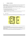
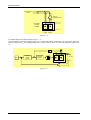
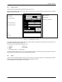
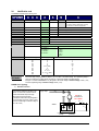
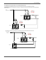
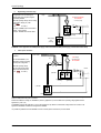
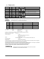
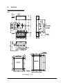
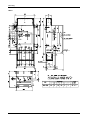
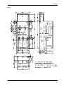
SILCOPAC SPDMR
RECTIFIER/REGENERATIVE CONVERTER
FOR DC BUS
Answer Drives S.r.l. - Partially owned by Ansaldo Sistemi Industriali -S.p.A.
answerdrives.com
SILCOPAC SPDMR
DIGITAL RECTIFIER/REGENERATIVE CONVERTER FOR DC BUS
Code:
Revision:
IMSPD026I
0.4
SW Version:
Date:
0.2 NRG
Dec-07
For further information and comment, please contact us at:
www.answerdrives.com
Answer Drives S.r.l. thanks you for choosing a product of the SILCOPAC family and for any useful advice aimed at the improvement of this manual.
TABLE OF CONTENTS
PREFACE
III
GENERAL SAFETY PRECAUTIONS
IV
CHAPTER 1A: GENERAL FEATURES'
1A.1 PRINCIPLE OF OPERATION
1A.2 RECEPTION CONTROL
1A.3 STORAGE
A1-1
A1-1
A1-3
A1-3
CHAPTER 2A: IDENTIFICATION CODE
A2-1
CHAPTER 3A: TECHNICAL DATA
A3-1
CHAPTER 4A: MOUNTING
4A.1 OUTLINE DIMENSION, MOUNTING, SAFETY CLEARANCE
4A.2 WEIGHTS AND DIMENSIONS
A4-1
A4-1
A4-7
CHAPTER 5A: CONNESSIONI INTERNE
5A.1 POSITION OF BOARDS
5A.2 CONNESSIONI INTERNE
A5-1
A5-1
A5-2
CHAPTER 6A: POWER CONNECTION DIAGRAMS
6A.1 SCHEMI DI COLLEGAMENTO DEI CIRCUITI DI POTENZA
A6-1
A6-1
CHAPTER 7A:
7A.1
7A.2
7A.3
CONNECTIONS
TERMINAL BOARDS
GROUND CONNECTIONS
CONNECTIONS DIAGRAMS
A7-1
A7-1
A7-3
A7-4
CHAPTER 8A: SIZING
8A.1 SPDMR
8A.2 AUTOTRANSFORMER
8A.3 LINE REACTORS
8A.4 PROTECTIONS
A6-1
A6-1
A6-2
A6-4
A6-5
CHAPTER 9A: OVERLOAD CURVES
A6-1
CHAPTER 1B: PARAMETERS
1B.2 TUNING PARAMETERS
1B.3 DRIVE PARAMETERS
B1-1
B1-5
B1-7
CHAPTER 1C: USER'S INTERFACE
1C.1 BASIC DIAGNOSTICS
1C.2 KEYPAD SPDI1 / SPDI2
C1-1
C1-1
C1-3
SPDMR
i
Table of contents
CHAPTER 2C: START UP
C2-1
2C.1 DESCRIPTION OF THE CONTROL SCHEME...............................................................................................C2-1
2C.2 PRELIMINARY CONTROLS............................................................................................................................C1-4
2C.3 CUSTOMIZATION OF THE P BOARD............................................................................................................C2-4
2C.4 LOAD RESISTORS FOR THE CURRENT TRANSFORMER) ........................................................................C1-5
2C.5 CUSTOMIZATION OF THE C BOARD ...........................................................................................................C2-7
2C.6 PARAMETRIZATION.......................................................................................................................................C1-9
2C.7 CALIBRATION OF THE TRANSDUCER.........................................................................................................C2-9
2C.8 VOLTAGE REFERENCE OF THE DC BUS..................................................................................................C1-12
2C.9 PRECHARGE AND DISCHARGE OF THE DC BUS ....................................................................................C2-12
2C.10 CURRENT REGULATOR AND VOLTAGE REGULATOR ............................................................................C1-13
2C.11 PARAMETERS BLOCK.................................................................................................................................C2-14
2C.12 JUMPERS OF "COREA" BOARD) ................................................................................................................C2-15
2C.13 LOCATION OF THE TEST POINTS IN THE C BOARD................................................................................C1-17
2C.14 TERMINALS AND TRIMMERS OF P BOARD ..............................................................................................C2-19
2C.15 PPRCRX BOARD..........................................................................................................................................C2-20
CHAPTER 3C: TROUBLESHOOTING
C3-1
CHAPTER 4C: MAINTENANCE.................................................................................................................................................C4-1
4C.1 ROUTINE MAINTENANCE .............................................................................................................................C4-1
4C.2 REPLACING THE THYRISTORS....................................................................................................................C4-1
4C.3 REPLACEMENT OF INTERNAL FUSES........................................................................................................C4-5
4C.4 REPLACING THE FANS .................................................................................................................................C4-5
4C.5 REPLACING THE C BOARD...........................................................................................................................C4-6
Answer Drives S.r.l shall not be liable for technical or editorial omissions in this manual, nor shall it be liable
for incidental or consequential damages resulting from the use of information contained in this manual.
ii
SPDMR
PREFACE
This manual provides detailed information and the safety rules concerning the installation and startup, use and maintenance of the converters
series SPDMR.
The manual has been written for Specialized operators involved in the installation, assembly, startup and maintenance of converters SPDMR,
and it has three different safety typologies, indicated by the specific symbols to identify information requiring special attention:
CAUTION!
Indicates an incorrect action which may determine dangerous situations for the operators.
Furthermore, it warns the personnel about possible dangers which may occur during the
maintenance operations.
Dangerous Voltage It signals the presence of high voltages with the subsequent risk of death or
electric shock for the operators.
It indicates the situations which may endanger the safety of people and/or damage the
equipment.
WARNING
It indicates a procedure which should be performed or avoided to perform in a correct way
operations of installation, repairing or replacement without damaging the inverter.
It indicates operations in whose field electrostatic discharges must be avoided.
☞
REMARK
3
Generic WARNING symbol.
It is used to explain an instruction, an operation of repairing or other.
Generic REMARK symbol.
CAUTION!
Make sure you fully read and understand this MANUAL before performing any intervention on the
SPDMR.
SPDMR
iii
Safety Precautions
SAFETY PRECAUTIONS
This section contains information about safety necessary and useful for the personnel operating with the SPDMR. The information is general
and concerns the risks, for operators or for maintenance personnel, related to the operation and maintenance of the converter. The lack of
observance of these rules may cause an hazard to the safety of people, with risk of death and of damaging the inverter, motor or operating
machine.
Before operating with the unit, read the safety instructions.
CAUTION!
All the operations of electric maintenance and installation on the SPDMR must be performed by qualified
technicians.
All the standard electric safety procedures must be respected:
• Never touch inside the converter; only after making sure there is not a high temperature and/or in
voltage.
• Always wear protection shoes insulated, in rubber and protection glasses.
• Never work alone.
• Never connect to the system any grounded device of measurement or oscilloscope.
• Never remove safety screens.
• Always pay maximum attention when handling components or performing measurements inside the
panel.
DANGER!
•
The SPDMR and all the other devices connected MUST BE GROUNDED IN A SUITABLE WAY.
•
The voltages on the terminals of output of the SPDMR are dangerous, be it when the drive is activated, be it when the same is not
operating. Also consider that the motor may turn in any moment as soon as the power supply is connected.
If the drive is installed in the panel, never operate it with the doors of the panel open.
•
DANGER! RISK OF FIRE, SERIOUS DAMAGE!
•
Several converter has not internal fuses; foresee suitable fuses (see Chapter 8 for caliper and type). Do not use fuses different from
those specified; wrong fuses may cause fire, serious damage to personnel equipment and/or parts connected nearby. Some units
need auxiliary fuses for the separated lines related to the fans and auxiliary circuits.
Do not apply power to the drive if you presume that inside of the container or of the components humidity has penetrated, dust or
•
caustic/corrosive chemical agents.
DANGER! RISK OF FIRE, SERIOUS DAMAGE OR INJURIES!
SPDMR are devices of open type and must be installed strictly according to the instructions of this MANUAL and in total agreement
•
with the standards and rules in force.
•
Never store flammable material inside, over or near the inverter.
IT IS ABSOLUTELY FORBIDDEN TO
•
WARNING
•
•
•
iv
Operate the drive with voltage greater then the 10% of the rated value.
Apply power to the terminals of output of the SPDMR.
Connect SPDMR in parallel, directly on the terminals in output
Connect capacitive loads to the terminals in output of the SPDMR
SPDMR
Safety Precautions
DANGER! RISK OF DEATH OR ELECTRIC SHOCK!
Before performing maintenance on the unit, strictly follow these safety points:
•
Perform the procedure of block/exclusion of electric power supply and open the main
disconnecting switch of the panel.
•
Make sure that all the power supplies which reach the SPDMR (main and auxiliary power supply)
are disconnected before performing maintenance on the drive.
Await at least three (3) minutes after disconnecting power supply before performing maintenance
on the unit. Refer to the safety plate existing on all the inverters.
The SPDMR is supplied with many automatic functions of reset and restart which can restart
automatically the unit. Do not activate these functions if there are dangerous situations.
Do not change the distances of insulation, nor remove materials and insulation covers.
Coordinate the voltage and the rated current of the load.
If you must perform some insulation tests on the motor and on the cables, first disconnect the
cables from the drive. Do not perform on the components of the SPDMR of the test by high
potential.
Pay attention not to damage any part of the SPDMR during the movement.
Protect the drive from atmospheric agents and adverse environmental conditions (temperature,
humidity, vibrations, collisions, etc). If you must store temporarily the inverter outside, take special
precautions (see Chapter 2).
DANGER •
•
•
•
•
•
•
The SPDMR contains components sensitive to the electrostatic charges; such components may be
damaged if handles in a non suitable way. During the operations of maintenance or replacement of the
electronic cards, follow the points indicated here below:
CAUTION!
Use a kit of maintenance for the electrostatic charges. You must take suitable precautions against the
electrostatic discharge (ESD):
Wear static belts suitably grounded.
Handle the cards from the edges.
The cards should not enter in contact with highly insulating materials as plastic sheets, insulating
surfaces, parts of synthetic tissues.
The cards shall be located on conductive surfaces only
The cards must be packed in conductive sheets before the shipment.
Warranty and limitsof liability
WARRANTY: for the conditions of warranty please refer to the module “GENERAL CONDITIONS OF WARRANTY” enclosed to the Order
Acceptation.
LIMITS OF LIABILITY: Answer Drives S.r.l. shall not be considered liable for missing technical information or errors in this manual,
nor for accidental damages due to the use of the information contained in this manual.
SPDMR
v
Safety Precautions
vi
SPDMR
A
GENERAL FEATURES
The SILCOPAC D in the version for the regenerative braking (abbrev. SPDMR) are AC/DC converters for the power supply in direct current of
the inverters, series GT3000
They are used in the applications in which there are drives performed with asynchronous motors, fed by one or more inverters connected to a
common bus d.c., where the needs of the plant require special modalities of braking or a frequent use in regenerative operation.
In the classic configurations the braking power of the motors is dissipated on suitable resistance but, in the applications in which this energy is
considered as important, it is convenient to use a converter DC/AC connected in antiparallel on the Bus DC to recover to the mains power
supply the current generated by the group inverters-motors.
The control circuit is digital and it is single for the whole series SPDMR which ranges from size 110Acc to 3800Acc.
The use of digital techniques offers important advantages:
• The drive can be easily configured via software according to the system characteristics;
• you can have a powerful diagnostics on the conditions of the drive;
• the operator can interact with the drive through a user’s interface which allows him to exchange and display the data, commands, different
information;
• It is possible to connect the drive in a centralized system of digital control, through a serial communication connection.
1A.1
Principle of operation
The part of power of the converter is made of two three-phase Graetz bridges by thyristors connected in antiparallel (figure 1.1 - 1), the first one
to supply the bus d.c. (operation as feeder), the second to recover in the mains the energy generated by the inverters (regenerative operation).
SPDMR
Rectifier
C/L+
bus d.c.
U1/L1
V1/L2
W1/L3
Regen
1U2/1T1
1V2/1T2
1W2/1T3
D/L-
Figure A1.1 - 1
The control circuit commands the two bridges in order to keep constant the voltage on the bus d.c., either during the motorizing operation of the
inverters, or during the regenerative operation.
The SPDMR converters have been designed to operate in regenerative mode in a continuative way, up to the rating current and their use allows
an important saving of energy in those cases in which the inverters frequently toggle from motorizing to regenerative operation.
Besides the normal operations of power supply of the bus d.c. and of regenerative braking, the converter SPDMR can be used also to perform
the precharge of the bus d.c.
To ensure the correct operation in regenerative mode with constant output voltage, the voltage of power supply of the regenerative bridge must
be risen by 20 ÷ 25% with an autotransformer, compared to the power supply voltage of the rectifying bridge (figure 1.1 - 2).
A1-1
SPDMR
General features
Power supply
mains
step-up
autotransformer
+
Reversible
converter
SPDMR
–
Rectifier
bridge
Regenerative
bridge
Figure A1.1 - 2
The simplified diagram of the control is illustrated in figure 1.1 – 3.
The control operates so that when the voltage on the bus d.c., by effect of the operation in regenerative mode of the inverters, tends to rise
besides a reference value Vref , the regenerative bridge starts to conduce current from the bus d.c. to the mains, keeping the voltage at value
Vref .
Vrif
+
–
DC bus
Voltage
regulator
–
+
+
Current
regulator
DC Bus
–
Figure A1.1 - 3
A1-2
SPDMR
General features
1A.2
Reception controls
Upon the reception, the packaging must be integral and without signs of shocks.
When opening the packaging, check that the content corresponds to the equipment ordered, verifying the code which is located on the plate
applied on the side of the converter.
SPDM Identification
Serial Number
Product test date
Power supplì Voltage
Line Frequency and Phases
Rated output Voltage (V)
Rated output Current (A)
Code
Bar Code
Figure A1.2 - 1: Plate applied to the converter
Verify that there are eventual options required. The options (normally supplied as separated) are accompanied by the accessories and the
instructions for installations and startup with the drive.
Each equipment is accompanied by the following documents:
•
•
•
•
Product card
Test report
Manual
Parameterization sheets
(Code mod.25)
(Code 8CP9998).
(Test configuration)
Verify that the equipment does not show any sign of damage, checking the status of the framing and the closing front panel; check that the
internal connections are integrated and correct; also check the integrity of the cards.
1A.3
Storage
If the converter is not installed immediately, it must be stored in a clean and dry environment, keeping it in its original packaging. Where the
mentioned conditions cannot be observed, protect the equipment with waterproof coverings.
The storage temperature must range between –30°C and +85°C.
SPDMR
A1-3
General features
SPDMR
SCHEDA PRODOTTO / PRODUCT SHEET MOD. / TYPE 25-9
A.O. / ORDER CONF.
CONSEGNA RICHIESTA / DELIVERY TIME:.
CLIENTE / CUSTOMER.
Euro
ORDINE CLIENTE / P.O.:.
1
2
QUANTITA` / QUANTITY
CONVERTITORE / CONVERTER
3
RETE DI ALIMENTAZIONE./ POWER SUPPLY.
4
5
MANUALE IST.
USER MANUAL
S Italiano/ Italian
S Francese/ French
S Inglese/English
S Tedesco/ German
OPZIONI / OPTIONS
6
7
SPDI1
SPDI2
8
SPDKS
9
10
11
12
13
14
15
16
17
SPRI1
Kit remotaggio connettore SPDI1/2 /SPDI1/2 connector remote. kit
SPDI/O
Espansione I/O digitali / Logic I/O Expansion
SPDS1
Seriale RS485 / Serial link RS485
FLAT-CABLE
SPDI1/2 - SPRI1
FILTRO RC /RC FILTER
REATTORE TRIFASE / THRE PHASE LINE REACTOR
ATRS 50
AUTOTRASFORMATORE SINCRONISMO
S 415-440-480-500/380
ATRS 22
SYNCHRONISM AUTOTRANSFORMER
S 220-240/380
FUSIBILI U.R.
S lato CA / AC Side
Q.ta’ / Q.ty
U.F. FUSE
S lato CA / AC Side
Q.ta’ / Q.ty
S lato CC / DC Side
Q.ta’ / Q.ty
S lato CC / DC Side
Q.ta’ / Q.ty
BASE PORTAFUSIBILE.
S 80 mm
Q.ta’ / Q.ty
FUSE HOLDER
S 110 mm
Q.ta’ / Q.ty
AL24
ALIMENTATORE 24VC.C. PER I/O DIGITALI / LOGICS I/O 24 VD.C. POWER SUPPLY
18
19
20
Tastiera / Keypad
Tastiera con connettore CENTRONICS
Keypad with CENTRONICS connector
Kit di remotaggio SPDI1/SPDI1 remote kit
28730753
25908304
25908306
20642202
223862
204699
206698
20653
21242
20653
21242
206535
212430
420166
TOTALE / .TOTAL AMOUNT
COMPILATORE / EDITOR:
A1-4
APPROVAZIONE / APPROVED BY:
DATA / DATE:
SPDMR
2A
Identification code
The SPDMR is identified by the following mark:
SPDMR
X X X
X
X
N
X
SUFFIX
50 = Frame V (version 2 fan)
51= Frame IV without collector bars (CT loose)
40 = Frames IV-V with fuses trip indicator
CONNECTION
R = reverse bridge generating
F = forward bridge motoring
blank = base version (forward and reverse bridges)
FAN POWER SUPPLY VOLTAGE
S = 230V / 60Hz
D = Standard version
G = 440V 60Hz 1,65A
POWER SUPPLY VOLTAGE
4quadrant
2 quadrant (connections R-F)
D = 400/500 V
G = 500/625 V
K = 690/860 V
W= 750/937 V
REMARK
G = 500 V
K = 690 V
W= 750 V
M= 850 V
N= 950 V
CURRENT (A)
Power supply voltage
frame
110
350
600
750
1K0
1K5
1K7
2K0
2K5
3K6
3K8
G
G
G
K
G
K-W – (NDR)
K
D-G
G–K-W
G – K - W – (NDR)
G
I
II
III
IIILL
IIILL
IV
IV
IV
V
V
V
The power supply voltage (specified by letters D, G or K) refers to the rectifier bridge. The regenerating bridge is
sized to be supplied with a voltage which is at maximum 1.25 times the voltage of the feeding bridge.
Example: on converter SPDMR600G it may be applied at the rectifier bridge a maximum voltage of 500V (+10%)
and to the regenerating bridge a maximum voltage of 625V (+10%).
SPDMR Circuit Typology
1)
Standard connection”
It is the standard application described in this
manual: it is used a four quadrant converter.
The letter that identifies the power supply
voltage refers to the forward bridge.
(for example W means that it may be applied to
the forward bridge a maximum voltage of 750V
and to the reverse bridge a maximum voltage of
1,25 * 750 = 937V).
Vin = power
supply voltage
ATR step-up
autotransformer
Vs = 1,25Vin
+
Fus.
L
SPDMR
D
–
Forward bridge
motoring
SPDMR
Reverse bridge
generating
A2-1
Circuit Tipology
This configuration can be made also with two or four quadrant parallel bridges (RTTR).
The parallel between the SPDMR and rhe RTTR must be done taking the same criteria used for SPDM and RTT bridges.
If the parallel is made with four quadrant RTTR, it is necessary to double the circuit on DC side composed by the choke, the free wheeling
diode and the fuse.
Vin =
Power supply
ATR Step-up
autotrasnformer
Vs = 1,25Vin
Fus. L
+
SPDMR
D
–
Forward bridge
motoring
Reverse bridge
generating
ATR Step-up
autotrasnformer
Vs = 1,25Vin
+
Fus. L
RTTR
D
–
Forward bridge
motoring
Reverse bridge
generating
If the parallel is made with two quadrant RTTR, it is not necessary the choke, the free wheeling diode and the fuse.
Vin = Power
supply
ATR Step-up
autotrasnformer
Vs = 1,25Vin
+
Fus. L
SPDMR
D
–
Forward bridge
motoring
Reverse bridge
generating
+
RTTR
–
Forward bridge motoring
A2-2
SPDMR
Circuit Tipology
2
Regenerating connection only”
Vin = power
This application use a diode bridge for
motoring (RTD) and a thyristor bridge for
regenerating SPDMR.
supply
TR step-up transformer
Vs = Vf/1,05
Vf = Braking voltage
Define the operating voltage class according
the secondary voltage (Vs) of the
transformer.
(ex. G
Vs= 500 V)
-
The output +SPDMR must be connected to
terminal – of the RTD and
the output –SPDMR to the terminal +RTD
Fus.
L
+
D
–
+
+
SPDMR Thyristors bridge
(regenerating)
Diodes bridge
RTD
(motoring)
-
WARNING!: in this application the SPDM power supply must be insulated from RTD power supply ( a transformer must be used).
3
Twelve pulse connection
This application use a two
converters.
Vin=voltage
power supply
ATR step-up
autotransformer
TR
The converter SPDMR a) is a
sinle bridge converter (motoring)
in twelve pulse configuration.
Vs = 1,25Vin
Define the operating voltage
class according the secondary
voltage of the transformer TR.
(ex. G
Vs= 500 V)
Fus.
Reactor
L
b)SPDMR
+
D
–
Forward bridge
motoring
Reverse bridge
regenerating
+
a) SPDMR
–
Forward bridge motoring
Application 2-3: SPDMR are identical to SPDM (2 quadrant) [The only difference is the control bord (“COREA” instead of CONDB)].
Refers to SPDM manual for power connections.
With the same BUS DC voltage, the SPDMR two quadrant (application 2) must be suitable for an operating voltage greater than the
application 3 ( at list 1,25)
The SPDMR concerning the applications 2 and 3a are identical, the only difference is the internal voltage transducer connection. The
applications 3b SPDMR is identical to the application 1SPDMR.
It is possible to parallel the converter SPDMR: The slave converter (without control board) is named RTTR
SPDMR
A2-3
Circuit Tipology
A2-4
SPDMR
3A TECHNICAL DATA
TYPE
SIZE
SPDMR110G
SPDMR350G
SPDMR600G
SPDMR750K
SPDMR1K0X
SPDMR1K5X
SPDMR1K7X
SPDMR2K0X
SPDMR2K5X
SPDMR3K6X
SPDMR3K8G
I
II
II
IIIL
IIIL
IV
IV
IV
V
V
V
CURRENT
A
110
350
600
750
1000
1500
1700
2000
2500
3600
3800
LOSSES
W
350
1100
1850
2700
3700
5400
6100
7150
8900
12700
14100
MAINS VOLTAGE (1)
D
G
K
W
x
x
x
x
x
x
x
x
x
x
x
x
x
x
x
x
x
x
BLOWER
with two fans single phase 220÷230 V 50 / 60 Hz0.15 A
with a fan single phase 220÷230 V 50 / 60 Hz0.35 A
with a fan single phase 220÷230 V 50 / 60 Hz0.88 A
with a fan three phase 380÷400 V 50 Hz / 440 V 60 Hz
2.2 A
with a fan three phase 380÷400 V 50 Hz / 440 V 60 Hz
1.7/2.A
Table 3A.1
The mains voltage indicated is the power supply voltage of the forward bridge. The power supply voltage of the
recovery bridge must be 1.2÷1.25 times that of the forward bridge.
REMARK
(1)
X
Power supply voltage
Feeding bridge VON [V]
Recovery bridge VREG [V]
3 x 380÷415 ±10%
3 x 460÷520
3 x 440÷500 ±10%
3 x 530÷625
3 x 660÷690 ±10%
3 x 790÷860
3 x 750 ±10%
940
3 x 950 ±10%
D
G
K
W
N
Mains voltage
: power
: control
"D- G- K - W” ±10%
380 V ±15%
400 V +10% - 20%
Output voltage
Vout [V]
510÷560
590÷675
890÷930
1010
30 VA
30 VA
Frequency 45 - 65 Hz with automatic adaptation to the value of frequency and to the cyclic sense.
Dead zone on the current inversion:
Ambient Temperature :
Altitude :
min. 3,3 ms
0 - 40°C
Reduce the rating current by 1.2% for every °C
between 40°C and 65°C max .
0 - 1000 m a.s.l.
Reduce the rating current by 1% for every 100 m between 1000 and 3000 m max.
Storage Temperature.:
-30 +70°C
Relative Humidity :
95% max (without condensate)
The product line Silcopac D complies with the Standard IEC 146.1.1/1991 is coordinated compared to the conditions which can be applied to
the Standard CEI EN 60204.1/1993 (IEC 204.1/1992) "Electric equipment of the Machines ".
The compliance to the standard, which is harmonized to the Community Directives 2006/95/EC "Directive on Low Voltage " and CEE 89/392
"Directive on Machines ", allows the use of the product in a machine equipment undergoing CE markup.
The product line Silcopac D is also complying, according to the tests performed, with the EN61800-3.
The EN61800 is the EMC European Standard for adjustable speed electrical power drive system
CAUTION!
SPDMR
For safety reason, all fuses must be always provided with the auxiliary switch for trip indication.
The SPDMR frame V have the auxiliary switch as standard.
A3-1
A3-2
SPDMR
4A
MOUNTING
Outline dimension, mounting, safety clearance
SIZE I
SPDMR
A4-1
Mounting
SIZE II
A4-2
SPDMR
Mounting
SIZE III
SPDMR
A4-3
Mounting
SIZE IIIL
A4-4
SPDMR
Mounting
SIZE IV
SPDMR
A4-5
Mounting
SIZE V
A4-6
SPDMR
Mounting
Frame V (SPDM2K2-2K5-3K1-3K6-4K0)
FAN
The fan is delivered loose (not installed on the SPDM).
Up to 09.16.2005 two versions was available.
Version 1: standard .
Version 2: optional, (indicated with suffix 50 on the identification code).
After this date the version two is available only. The identification code for every SPDM will have the suffix 50.
NOTE:
the remarks above mentioned are valid also for the RTTR frame V.
VERSION 1
VERSION 2
4A.2 Weights and dimensions
Silcopac D
type
SPDMR110G
SPDMR350G
SPDMR600G
SPDMR750K
SPDMR1K0x
SPDMR1K5x
SPDMR1K7K
SPDMR2K0x
SPDMR2K5x50
SPDMR3K6x50
SPDMR3K8x50
SPDMR3K8G
SPDMR
Frame
I
II
III
IIIL
IIIL
IIIL
IV
IV
IV
V
V
V
width
mm
230
230
230
230
230
230
484
484
484
560
560
560
height
mm
320
420
570
875
875
875
1100(+212)
1100(+212)
1100(+212)
875(+355)
875(+355)
875(+355)
depth
mm
220
240
262
350
350
350
420
420
420
563
563
563
weight
kg
11
17
26
57
57
57
125
125
125
200
320
320
A4-7
Mounting
A4-8
SPDMR