1
INSTRUCTION
MANUAL
R- SERIES
0,37 kW - 2,2 kW
Inverter general purpose
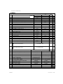
CONTENTS
pg
INTRODUCTION .............................................................................................................................................................. 1
SAFETY INSTRUCTIONS ................................................................................................................................................ 2
Product description ..................................................................................................................................................... 4
Guide to the choice ..................................................................................................................................................... 5
THECNICAL FEATURES .................................................................................................................................................. 6
Terminal block connections ......................................................................................................................................... 7
Power section ............................................................................................................................................................. 7
Power connections ...................................................................................................................................................... 7
Control section ............................................................................................................................................................ 8
Control connections .................................................................................................................................................... 8
Optional terminal features .......................................................................................................................................... 9
Connections .............................................................................................................................................................. 10
INSTALLATION INSTRUCTIONS .................................................................................................................................. 10
Installation gidlines .................................................................................................................................................... 12
Cables ...................................................................................................................................................................... 13
Protections ............................................................................................................................................................... 14
Braking unit ............................................................................................................................................................... 15
Operation .................................................................................................................................................................. 16
Control panel ............................................................................................................................................................. 17
Parameter changes ................................................................................................................................................... 19
INVERTER PARAMETERS ............................................................................................................................................ 20
I/o digital state .......................................................................................................................................................... 21
Parameters quick guide ............................................................................................................................................ 22
Function description: ................................................................................................................................................. 28
Frequency reference ................................................................................................................................................... 28
V / F characteristic .................................................................................................................................................... 31
Freq. jumps - Output freq. limitations - Jogging - Switching freq. - Accel./decel. ramps .................................................. 32
Motor data setting - Motor thermal protection - Prevention of motor stall - inverter lock .................................................. 33
Slip compensation - Instantaneous overload signalling - Prevention of short mains blackout - Pickup of motor in free
rotation (flying restart) - Automatic boost ................................................................................................................... 34
Programmable and non-programmable control inputs ................................................................................................... 35
Relay output (OUT-1) - Dynamic braking .................................................................................................................... 36
Analog output (OUT-AN ) - Direct current braking ........................................................................................................ 37
PID regulator .............................................................................................................................................................. 40
Reset - Autoreset - Protections and alarms ................................................................................................................. 42
MULTIDROP SERIAL LINE CONNECTIONS ................................................................................................................. 43
Serial line .................................................................................................................................................................. 43
Protocol MODBUS ..................................................................................................................................................... 43
ACCESSORIES ............................................................................................................................................................. 51
Programming key [ code KM-PRG ] ......................................................................................................................... 51
CONFORMITY - NORMS ........................................................................................................................................... 52
Identification of the different installation sections ....................................................................................................... 53
External dimensions ................................................................................................................................................. 53
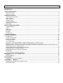
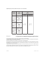
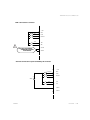
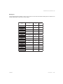
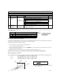
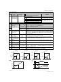
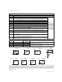
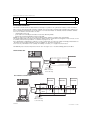
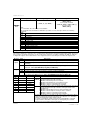
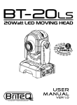
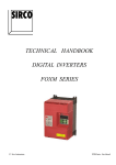
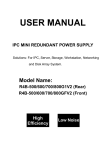
IDENTIFICATION LABEL
MODEL
OPTION
→
Output voltage
specifications
Load specifications
→
→
B
X
present
none
EMC Filter:
A
X
A filter
none
I/O:
X
E
M
O
T
Standard
Encoder Input
Analog Output
RS 485-O
Canbus
Software version:
X
standard
Applicable maximum
motor out:
004 →
008 →
011 →
015 →
022 →
R2M004XXXX
_
S/N
Input specifications
Braking unit:
INPUT
AC 220V -15% / 240V +10%
4,5A 50/60 Hz 1 PHASE
OUTPUT AC 0/220V 2,2A 0,1/480 Hz
0,37 kW AC 3Ph MOTOR
LOAD
made in Italy
CE
0,37
0,75
1,1
1,5
2,2
Serie's name
Voltage class : 2M = 220V single phase
2T = 220V three phase
4T = 380V three phase
kW
"
"
"
"
ENGLISH
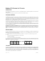
INTRODUCTION
Introduction
The R series Inverters allow an efficient and flexible control of motor speed. In this way, the asynchronous motor can be
used in a wider range of applications.
(3-phases models)®
- R series
R
series
single-phase and 3-phases, with a torque vector control.
The R series inverter series can be used not only for industrial application machinerys, but in many of general building
applications too.
Noise disappearance:
The noiseless operation of the inverter is due to a proper method of creating the waveform of the voltage that supplies
the motor.
Continuity of operation in power failure state:
In case of temporary power failure, the R series Drive inverter stops and starts again, and keeps the preset control
characteristics without having to stop the motor.
Easy operation with the extractable keypad:
The functioning interface is made of a panel consisting of four keys, one display with four 7-segment digits and three leds.
The display and the keys allow you to change all the inverter parameters so as to make it suitable to all applications.
The drive display allows the monitoring of controlled variables as frequency, current, output voltage, cos phi, power and
the storage of the last 4th alarms attempted.
Serial connection:
Besides being controlled from panel, the R series Drive inverter can be easily remote controlled and programmed through
serial connection by means of a proper communication protocol, or with remotable keypad.
However, the run, stop, speed reversal and change operations are performed, as usual, through terminal board.
The R series drive inverter supplies high torques at low revolution numbers without discontinuity thanks to the current
automatic control. It assures a safe start of the motor.
STMDRIVE
User Manual - 1-GB
SAFETY INSTRUCTIONS
General safety instructions
Before the drive installation, connections or any other operation, read carefully its instruction manual to respect correctly all
safety instructions.
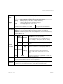
Throughout the text, the following Danger symbols indicate paragraphs containing particular instructions that must be
carefully read so as to assure safety conditions to users:
This warns the user about the presence of a dangerous voltage. It indicates the presence of High
Voltage conditions that can cause serious damages or even death.
This indicates a general danger or very important operation notes.
Warnings
• Electrical devices can represent a risk source for personnel safety. It is therefore necessary to know all usage
methods and unit control devices perfectly before using the machine.
• The machine should then be used by skilled personnel only, aware of the installation and operation rules, in
compliance with the safety and protection standards, and able to interpret all danger warnings.
• In particolari condizioni di programmazione della regolazione, dopo una mancanza di rete, la macchina
potrebbe avviarsi automaticamente.
UL normative instructions
• The inverter must be installed in ambient with protection pollution degree no. 2.
• Risk of electric shock. Disconnect drive power supply before any drive operation.
• High Voltage level is still present after drive power off. Device is live up to 5 minute after removing input Voltage, so do
not perform any drive operation during this period. All the drive terminals are under risk of electric shock: PE, L1, L2,
( L3 for 3-phases type), U, V, W, R, +DC.
• Use exclusively copper cables with working temperature equal and above 60/75°C.
• Make terminal connections of regulation section using a correct nipple cable.
• Use appropriate tools to screw down drive terminals regulation section.
• Tightening torque and cables cross section for all drive sizes are listed below.
2-GB - User Manual
STMDRIVE
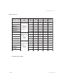
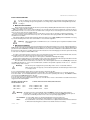
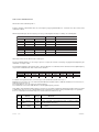
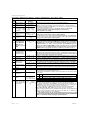
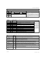
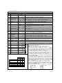
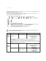
Tightening torque of drive terminals ans cables cross section allowed
Inverter
model
Input
voltage
Cables cross section
AWG
[mm2]
Power
Regulation
24 - 16
(0.2 - 1.5)
26 - 18
(0.2 - 1)
R2M-004-…
R2M-008-…
R2M-011-…
R2M-015-…
R2M-022-…
R2T-004-…
R2T-008-…
R2T-011-…
R2T-015-…
R4T-004-…
R4T-008-…
R4T-011-…
R4T-015-…
R4T-022-…
Warranty notes
220 Vac -15%
240 Vac +15%
50/60Hz
Single-Phase
Terminals: L1 - L2
220 Vac -15%
240 Vac +15%
50/60Hz
3-Phase
Terminals:
L1-L2-L3
380 Vac -15%
460 Vac +15%
50/60Hz
3-Phase
Terminals:
L1-L2-L3
The warranty conditions are scheduled by the supplier at the moment drive purchased.
The supplier decline his responsibility from drive damaging during shipping or unpacking.
The unit is designed for motor speed control only. Do not use it for other applications.
The manufacturer is not responsible for damages deriving from improper use or installation or inadeguate ambient conditions,
as well as for damages due to improper rated values.
Nor will, the manufacturer be responsible for consequential or accidental damages.
No intervention has to be perfomed on parts inside the machine: when installing, just remove the terminal board cover panel.
Any tampering or use of spare parts or other parts not supplied by the manufacturer, besides making the warranty void, may
cause damages and/or serious accidents.
Starting from drive startup its warronty period is 24 months or no more than 36 months (refer to the soles conditions agreed).
The technical data contained in this manual are to be considered correct at printout time. The manufacturer, however, reserves
the right to change, without notice, both the contents and the technical data of the product.
STMDRIVE
User Manual - 3-GB
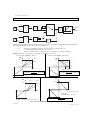
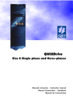
PRODUCT DESCRIPTION
Product description
The R series Drive inverters are converters with D.C. intermediate circuit. When connected with a common single or
threephase mains, they produce a threephase, variable-frequency, A.C. voltage, used to control the speed of three-phase
asynchronous motors.
The control circuit has a properly programmed microprocessor.
The control keyboard allows the user to easily and quickly enter any parameter necessary for the required working conditions.
The three-phase, variable frequency, alternate voltage, controlled by microprocessor, is delivered to the motor through a power
module which uses the most recent IGBT technology.
The use of microprocessor, IGBT technology and modulation frequency programming, assures an extremely accurate and
silent operation.
The software, properly developed for power electronics, allows an accurate and quick control of motor speed, start and stop
times which can be independently adjusted, and other operation conditions:
• Speed control via the current adjustment according to the load, thus allowing the automatic adjustment to the process.
(available in the R series version).
• Automatic boost that allows a safe start of the motor by acting on the torque as a function of the load. Presence of high
torques and rotation evenness at very low frequencies too. (available in the R series version).
•
Direct current braking, with programmable duration and value, allowing a comfortable motor stop.
• Presence of a PID-type inner regulator, which can be freely configured, to control the motor speed and/or torque.
• Presence of a standard series line, with programmable transmission modes, to remote program and/or control the
converter.
Further, the unit is provided with a programmable relay output and an analog output that indicates, through selection, the trend
of the main values of the inverter.
4-GB - User Manual
STMDRIVE
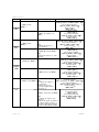
PRODUCT DESCRIPTION
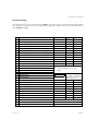
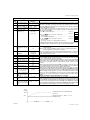
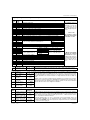
Guide to the choice
Inverter
Input
voltage
model
R2M-004-…
R2M-008-…
R2M-011-…
R2M-015-…
220 Vac -15%
240 Vac +15%
50/60Hz
Single-Phase
Terminals: L1 - L2
R2M-022-…
R2T-004-…
R2T-008-…
R2T-011-…
R2T-015-…
220 Vac -15%
240 Vac +15%
50/60Hz
3Phase
Terminals:
L1-L2-L3
R2T-004-…
R2T-008-…
R2T-011-…
R2T-015-…
380 Vac -15%
460 Vac +10%
50/60Hz
3Phase
Terminals:
L1-L2-L3
R2T-022-…
PV heat
Min. value of
external
inverter
resistor
dissipation
[ohm]
[W]
Inverter
output
[kVA]
Rated
output
current
[A]
PN motor
recommended
[kW]
1.0
2.2
0.37
20
100
1.6
3.9
0.75
30
100
2.2
5.5
1.1
40
100
2.9
7.0
1.5
50
50
3,8
9,0
2,2
90
50
1.0
2.2
0.37
20
100
1.6
3.9
0.75
30
100
2.2
5.5
1.1
40
100
2.9
7.0
1.5
50
100
0,9
1,3
0,37
20
100
1.6
2,2
0.75
30
100
2.1
2,8
1.1
40
100
2.9
4
1.5
50
100
3,8
5,5
2,2
90
100
Protection degree IP 20
STMDRIVE
User Manual - 5-GB
TECHNICS CHARACTERISTICS
Input
voltage
single-phase, 220/240 V, tolerance -15%+10%;
voltage
frequency
frequency from 47 Hz to 63 Hz.
three-phase from 0V to input voltage.
from 0.1 to 480 Hz; resolution 0.1 Hz (0,01 Hz if set via serial line).
(switching frequency : from 1kHz to 18 kHz, programmable).
continuous output: nominal current of the inverter type .
overload capacity : to 150% for 30" every 20'.
acceleration time: 0.01" to 9999"
via the terminal board it is possible to
accel./decel. deceleration time: 0.01" to 9999"
select up to 4 previously programmed
" S " characteristic: 0.0" to 10.0"
ramp torques
ambient temp.: from 0°C [32°F] to +40°C [104°F] (temperture close to the inverter);
storage temp.: from -20°C [-4°F] to +60°C [140°F]
Environment ventilation: self or forced cooling according to the power; free of dust or corrosive gases
conditions
humidity: from 20% RH to 90% RH, non-condensing
installation: max. 2000 meters [3280 feet] on the sea level (for higher levels, the features have to be derated)
protection degree: IP 20
Output
current
start ( forward run ) or programmable,
direction ( reverse run ) or programmable,
Digital
external alarm (the action is programmable).
optoisolated Operation
2 other signals selectable between:
NPN or PNP signals
alarm reset; frequency selector: F1, F2, F3; ramp selector: T1,
T2; inverter enabling; d.c. braking enable; start or d.c. braking;
flying restart.
Inputs
Frequency
reference
Analog
External
connections
Relay
Outputs Indications
Analog
Serial
RS-485
selectable according to the voltage: 0/10V , -10V/+10V
or to the current:
0/20 mA or 4/20mA with programmable gain
and offset
configurable for: alarm, inverter, frequency, ramp condition etc.
-10/10V 10 bit (optional) or 0/10V 8 bit (standard): programmable
gain and offset; the signal value can be proportional to:
frequency, voltage, output current or torque, cos ϕ or output
power.
2-wire operation: max. 32 inverters can be parallel-connected;
the transmission parameters are programmable; it can be used
to replace the keyboard panel
Protections
limits: overcurrent, overvoltage, undervoltage (with programmable threshold), inverter overtemperature;
inverter overload, motor overload, braking resistance overload, inner fuse cutoff, phase to phase and
phase to ground shortcircuit, error in the values of the stored parameters.
Standard
functions
programmable V/f characteristic, slip compensation , autoreset (programmable intervention time and
retry number), jump frequency, upper and lower frequency limits, flying restart , power "dips" prevention ,
PID regulator, motor stall or inverter fault prevention, overmodulation, potentiometer function.
6-GB - User Manual
STMDRIVE
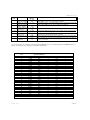
TERMINAL BLOCK CONNECTIONS
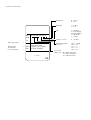
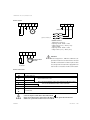
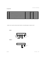
Power Section
R
+DC
PE
U
V
W
PE
GROUND
R
L1
(L)
L2
(N)
L3
(L3)
M
(3-phases models)®
POWER SUPPLY:
-Single-phase (3-phases)
frequency: 50 Hz - 60 Hz +/- 5Hz;
voltage: 220 V (-15%) - 240 V (+10%).
-3-phase (380V)
frequency: 50 Hz - 60 Hz +/- 5Hz;
voltage: 380 V (-15%) - 460V (+10%).
R
+DC
U
V
W
Attention!
R
M
THREE-PHASE
MOTOR
For the single-phase 1,1kW and 1,5 kW sizes, the
ground connection of motor side must be connected
to the M3 screw heatsink. For all the 3-phases 380V
Braking
resistance
sizes, the ground connection of line supply and motor
side must be connected to the M3 screw heatsink.
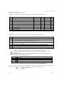
Power connections
TERMINALLS
PE
L1
L2
L3
R
+DC
PE
U
V
W
FUNCTION
GROUND CONNECTION
Single-phase
MAINS POWER SUPPLY: 220V
Three-phases
Note: The external braking resistor drive terminals are NOT protected by
short circuit and minimum resistor value not allowed.
BRAKING RESISTANCE
Positive of the d.c. circuit
POWER GROUND
(1,1kW and 1,5kW single phase and in 3-phases 380V are not included)
THREE-PHASE OUTPUT
(TO THE MOTOR)
Connect only one cable to the Ground terminal
Other connections to the ground must be done on main ground terminal of the
cabinet or system where the inverter is installed.
STMDRIVE
User Manual - 7-GB
TERMINAL BLOCK CONNECTIONS
2
3
4
RUN
EF
IN4
5
6
IN 5
CM-IN
7
14
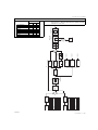
Relè
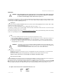
Programmable output:
active when the motor is
running, or....
15
16
17
9
GND-A
18
+
10
LNK+ LNK-
J4 J11 (*)
19
J1 (**)
+10V
Analog input
13
Analog output
12
RS - 485
8
+24V GND-D
REL-NC REL-CM REL-NO OUT OUT-AN IN-Analog +10V REV-V
11
Digit. inp. reference
Inp. pow. supp.
Input common
Digit. input 5
Digit. input 4
Ext. alarm
1
REV
Digital output
Control side: the shield
has not to be connected
Marcia
Direction
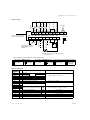
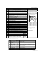
Control section
Potentiometer
-
Programmable 0/10 V output :
proportional to the motor output frequency
or to other values.
(*)Analog Inputs jumper configuration (16 and 18 terminals)
J4 configuration of REF-V (18 terminal)
0-20 mA 4-20mA
0-10 V or -10V/10V
J 11 configuration of REF-AUX (16 terminal)
(**) J 1 configurat. of connection ground (PE terminal)
0-20 mA 4-20mA
0-10 V or -10V/10V
GND floating
GND-D on PE
(8 terminals)
Control connections
REV
RUN
EXTFLT
IN4
IN5
CM-IN
+24 V
GND-D
LNK+
LNK OUT1-NC
OUT1-CM
OUT1-NO
OUT
OUT-AN
REF-AUX
+10V
REF-V
GND-A
1
2
3
4
5
6
7
8
9
10
11
12
13
14
15
16
17
18
19
8-GB - User Manual
SIGNAL TYPE
FUNCTION
TERMINALS N.
Reversal
Run
If b-00=1:
Backward run
Forward run
Alarm from outside
Configurable digital input
Configurable digital input
Digital input common
Aux. power supply for digit. inputs
Optical couplers: 24 V, 6 mA
P-42
P-43
24 V +/- 5%
300 mA
Reference ground for digit. inputs
RS-485 serial line inputs
Contacts of the configurable output relay
P-44
Open collector digital output
P-46
Configurable anal. output
P-48
Auxiliary progr. analog input: AUX-V
P-47
Potentiometer voltage for speed reference
Programmable analog input: REF-V
Common for analog input/output circuit
120 V ac with 0,5 A or 24 V dc with 1 A
50 V 50 mA
0 / 10 V 8bit (standard) or -10 / +10V 10bit (opz.)
0 - 10 V or -10 +10V Ri= 20 KOhm / 0 - 20mA Ri= 500 Ohm
10V +/-5% 10mA
0 - 10 V or -10 +10V Ri= 20 KOhm / 0 - 20mA Ri= 500 Ohm
STMDRIVE
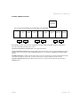
TERMINAL BLOCK CONNECTIONS
OPTIONAL TERMINAL FEATURES
JP6
optional RJ
connector
JP5: removable terminal (OPZ-CAN and/or OPZ-ENC and/or OPZ-SOP)
CAN+
V+
J6
SHIELD
J5
V-
CAN-
J8
ENC.A+
J7
ENC.A-
ENC.B+
J9
ENC.B-
J10
Depending by customer request, the drive regulation board can be equipped with different optional configurations.
The request must be present in the phase order.
OPTO-COUPLED SERIAL LINE (OPZ-SOP): refer to page 43 for details.
CANBUS PROTOCOL (OPZ-CAN): the power supply range of this circuit is 12-30V, so it can be applied on V+ and Vterminals, JP5 connector. CAN+, CAN- and SHIELD terminals are also available for CANOPEN and/or DEVICENET
protocol.
ENCODER (OPZ-ENC): reading of encoder signal. JP5 connector is assigned as encoder input, defaulted to 24V logic
level (J9 and J10 jumpers not inserted) . For 5V encoder logic level, J9 and J10 jumpers must be inserted.
OPTIONAL BOARDS (OPZ-ESE): through RJ JP6 connector it is possible to interface different optional board, as
PROFIBUS card.
STMDRIVE
User Manual - 9-GB
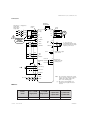
TERMINAL BLOCK CONNECTIONS
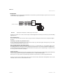
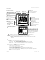
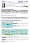
Connections
BRAKING
RESISTANCE
Three-phases / single-phase
supply 220V
Three-phases
supply 380V
Anelli di
ferrite
FILTER
WITHOUT IT
COMMANDS
ARE NOT
FUNCTIONING
Ferrite
toroid
R
L1 (L)
U
L2 (N)
V
L3
W
G
PE
M
7 + 24V
6 CM - IN
Reversal
Run
External alarm
OUT
AN
1 REV
15
0 / 10V factory-set
programmable analog output.
It is proportional to the output
frequency on the motor.
2 RUN
GND - A 19
3 EXTFLT
14
OUT 3
JOG
Alarm reset
Multi-function output
open collector
4 IN4
8
5 IN5
8 GND-D
OUT1-NO
PE (EARTH)
OUT1-NC
8 (*)
OUT1-CM
13
11
12
Multi-function
output active with
a running motor
17 +10V
Speed reference
4k7 Ω
18 IN-Analog
16 IN-Aux-V
19 GND - A
9 LNK +
RS - 485
Note: The connections stated for the control
keys are the most common solution for
a NPN control. Other examples are
given on the following page.
10 LNK -
(*) : PE reference point available on 8
terminal, only if J1 jumper has been
inserted.
EMC filter
Inverter
model
0.37 - 0.75kW
Single-phase
1.1 - 2,2kW
Single-phase
0.37 - 1.1kW
3-phase 220V
3-phase 380V
1.5-2,2kW
3-phase 220V
3-phase 380V
R series
optional internal
external
external
external
10-GB - User Manual
STMDRIVE
TERMINAL BLOCK CONNECTIONS
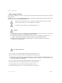
PNP connections controls:
7 + 24V
Reversal
Run
1 REV
2 RUN
External alarm 3 EXTFLT
JOG
Alarm reset
WITHOUT THE JUMPER,
COMMANDS ARE NOT
FUNCTIONING
4 IN4
5 IN5
6 CM - IN
8 GND-D
Control connections opto-isolated by the inverter:
+
7
+ 24V
Reversal
1
REV
Run
2
External alarm 3
RUN
EXTFLT
24V
JOG
Alarm reset
STMDRIVE
4
IN4
5
IN5
6
CM - IN
8
GND-D
User Manual - 11-GB
INSTALLATION INSTRUCTIONS
INSTALLATION GUIDELINES
In order to obtain a safe operation of the unit, assembly and start-up should be performed by skilled personnel only, according to the general regulations concerning safety conditions when working with high currents
or voltages.
•
Mechanical installation
Removal of the heat produced by the inverter is performed by ventilating with natural air flow, in low power models,
and by means of fan in all other models.
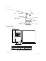
When assembling, leave a space of at least 40 mm (1.6"). from the sides and, on the heatsink side, 150 mm (6"). above
and below the inverter, soas to assure a free circulation of the cooling air. In case of stacking of more units, leave a vertical
space of at least 300 mm (12"). between them.
The site should assure the ventilation air is free from dust or corrosive gases, otherwise a regular cleaning of the cooling surfaces must be performed. Avoid, in any case, the condensation of the sprayed fluids. The ambient humidity
should never exceed 90%.
In working conditions, the temperature inside the cabinet should never exceed 40° C (104°F). If it should, it will be necessary
to perform a derating of the unit or a forced ventilation so as to avoid air stagnation.
Warning:
•
When calculating the overall dimensions, also consider the space required for installation of antinoise filters.
Electrical installation
The inverters are designed to operate in an industrial environment where high levels of electro-magnetic disturbance
(EMI) must be expected. Good installation practice usually ensure trouble-free operation, however it is suggested that a good
ground connection and RFI filters should be used. The RFI filters ensure a reduction of radiated or conducted interference when
the inverter is in a interference sensible environment. The instructions on the following page show how to perform the wiring
in order to be in compliance with the EMC norms.
In order to connect the inverter, just remove the cover which protects the power and control terminal boards; it can be
removed by acting on the clip placed on the front upper side of the cover itself.
The R series is foreseen for a single-phase or three-phases 220/240V and 380Vpower supply.
As for the power supply cables, we recommend to use two or three-wire shielded cables where the ground cable is external
and parallel to the shield; their dimensions must follow the values listed on page 3.
The same cable can be used for motor connection too. The cable length should never exceed 30 m (98"). If it should,
use additional inductances, series-connected with cables, to balance the parasitic capacities. In this case, a reduction
of motor voltage can be noticed.
Warning:
The inverter power supply must be protected by means of fuses or automatic switches.
Make sure the cables are properly connected and, in particular, check that the ground connection
is correctly locked.
In case of shielded power supply cables, ground connect the shield on both sides.
The power cables must be kept separate from the signal cables. The standards require the use of separate raceways.
For control cables, use a shielded cable with a section of at least 0.5 mm 2 (0.0008 spuare inches). The shield should be
connected to the terminal 19 on drive side only.
For connection of reference signals or serial line, use twisted cables.
Connect spark quenching units in parallel to relay coils, solenoid valves, remote control switches located near the unit, as
suggested on the following table:
REMOTE CONTROL SWITCH
OR SOLENOID VALVE
220 V, 240 V
220 V, 240 V
380 V, 460 V
>30 A
<30 A
CHARACTERISTICS OF SPARK QUENCHING UNIT
0.5uF + 100Ohm 1/2 W
0.1uF + 100Ohm 1/2 W
0.5uF + 100Ohm 1/2 W
250 V
250 V
1000 V
Warning: The failure protection circuit towards earth must ONLY protect the inverter against failures
towards earth, occurring on the motor cable or on the motor itself. It is NOT designed to protect
people who accidentally touch the motor or the corresponding supplying cable.
It is forbidden: to connect PFC devices to output terminals between inverter and motor;
to connect capacitors between output terminals or output terminals and earth;
Note:
It is not advisable to connect remote control switches to output terminals between inverter and motor
if, while their functioning phase, both the motor and the inverter are running.
12-GB - User
STMDRIVE
INSTALLATION INSTRUCTIONS
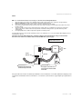
Cables
NB.: To connect the inverter it is necessary to conform to the following indications:
12345-
As for the power connections, the shielding must include only the two power conductors; the ground wire,
which is obligatory, must be external to the shield and run parallel to it.
Both the inverter side and the motor or filter side of the shield must be grounded.
The ferrite toroid must be put on the inverter side of the cable in a way to cover the part of the cable uncovered
from the shield.
The power cables must be kept separated from the signal cables; it is forbidden to install power and signal
cables in the same conduit or duct. It is important to hold motor wiring as far as possible from the power
supply wiring.
Use high quality motors, with low parasitic capacities towards ground.
The input filter increases leak currents towards ground; so it is advisable use a overcurrent switch with a tripping current
not lower than 100 mA .
The figure shows the wiring method in compliance with the stated standards by using an external filter.
Part of inverter models are available with an internal EMC filter (class A type).
Part of inverter models are
available with an internal
L3
L2
L1
PE
Control
terminal
Filter
Toroids
W
V
U
PE
+DC
R
Shielded cable and ground
connected only to one side.
main
M
For lengths lower than 20 cm,
it is possible to omit the shield
of the cable
If the system where the inverter is installed is provided with overcurrent switch, this one should be calibrated for a tripping current
not lower than 100 mA and for a time not lower than 0.1 sec. Furthermore, it must be able to support high frequency disturbance
events.
STMDRIVE
User Manual - 13-GB
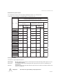
INSTALLATION INSTRUCTIONS
External fuses of power section
The external fuses of power section must be provided by the inverter user on AC input side.
In the table below are listed the recommended types for each inverter size.
F1 - Fuses type
Connections without three-phase reactor on AC input
R/C Fuses manufactured by
Drive
type
Bussmann Div. Cooper (UK) Ltd (200
KA A.I.C.)
Gould Shawmut (50 KA A.I.C.)
Qty
Ratings
Ratings
Mod. No.
Mod. No.
Amps
R2M004
R2M008
R2M011
R2M015
Vac
Amps
10 LCT
10
A25X10-1
10
2
12 LCT
12
A25X12-1
12
2
16 LCT
16
A25X15-1
15
2
20 LCT
20
A25X20-1
20
R2T008
6 LCT
6
10 LCT
2
250
240
R2T004
Vac
A25X6-1
6
3
A25X10-1
10
3
10
R2T011
16 LCT
16
A25X15-1
15
3
10 LCT
10
A25X10-1
10
3
A25X10-1
10
R2T015
R4T004
R4T008
10 LCT
10
420
3
430
R4T011
10 LCT
10
A25X10-1
10
3
R4T015
Inverter protections
L'inverter ha le seguenti protezioni interne:
Overvoltage:
Overcurrent:
Overload:
DC-Link voltage level protection. The inverter trips when the internal voltage of DC capacitors exceed
overvoltage threshold level.
overcurrent protection. The inverter trips when the output current exceed for one instant its preset
maximum level.
overload protection. The inverter trips when the output current exceed the overload max. allowed: 150%
for 30 sec. each 20 min.
Overspeed:
14-GB - User
the inverter is not provided by overspeed protection.
STMDRIVE
INSTALLATION INSTRUCTIONS
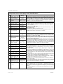
Braking unit
The internal braking unit is available as option. The external resistor must be mounted if the braking unit is used. Refer to the
chapter of parameters section for the correct settings.
STMDRIVE
Inverter
Type
Max Duty Cycle
%
PNBR
[W]
Min. RBR
[Ohm]
R2M004
20 %
300
100
R2M008
25 %
380
100
R2M011
25 %
380
100
R2M015
25 %
741
50
R2M022
25 %
741
50
R2T004
20 %
300
100
R2T008
25 %
380
100
R2T011
25 %
380
100
R2T015
25 %
741
100
R4T004
20 %
300
100
R4T008
25 %
380
100
R4T011
25 %
380
100
R4T015
25 %
741
100
R4T022
25 %
741
100
User Manual - 15-GB
INSTALLATION INSTRUCTIONS
Operation
WARNING Before turning the inverter on, make sure the cover is locked in position. After each turning
off, wait 3 minutes before opening the unit so as to allow the capacitors to discharge.
To avoid inverter damagings, wait 2 minutes before power on.
For safety reasons, at power on or after a reset due to an alarm, the inverter is factory-preset not to start even with run control
in active state. To start the motor, you should set the control first to OFF and then to ON (this safety precaution can be
intentionally cancelled through b-03 parameter).
Turning on
•
The inverter is not provided with an ON/OFF switch. This operation is performed by appliying the mains voltage. After voltage
application, the inverter performs a test.
If an error is encountered during this test, the display will show the message C Err
The display, consisting of four 7-segment digits, shows both letters and numbers. When turned on, it shows the output
frequency value (00 Hz if the motor is stopped).
The inverter is factory-preset to control three-phase asynchronous motors which operate with voltages and currents having
values corresponding to the inverter size.
Run
•
1 - Connect a 4.7 kOhm potentiometer for the speed reference(terminals 13,14,15 )
2 - Power supply the digital inputs ( terminal 5) with +24V. If the inputs have not to be isolated, it is possible to use
the power supply available on the terminal 6.
3 - Connect two contacts for forward and backward run control (terminals 2, 1, and 7/8 ) as shown on page 8.
4 - Close the run contact to start the motor . The motor is started at the frequency selected through the preset
ramp (default P-05= 5 seconds).
WARNING
If the factory - preset values should be modified to adapt the inverter to the application, it can
be made through the control panel where the actual values can be displayed, then modified, and
then permanently stored.
In case it is needed, the default values can be reset via the C02 function
Stop
•
To stop the motor, act as follows:
- Disable the run control. In this way, the motor is stopped with factory-preset ramp (P-06= 5 seconds from max.
frequency to 0 Hz).
- Or set to zero the speed reference potentiometer, so that the user has control over the motor stop.
Caution: in this case the motor, even though it is stopped, is still under voltage.
The motor does not start
•
If after enabling the run control, the motor does not start, first check that the connections shown on the previous pages have
been performed, then check that the factory-preset parameters meet the motor characteristics.
The parameter check is performed by using the keypad: press the M key until the P menu appears , then, throung the ⇑,
⇓ keys select the code of the parameter with the value to be checked and press the E key to read its value. The data of
the motor rating characteristics are important; they can be set via the parameters P-01, P-02, P-09 , P-11, P-12.
• Caption of the function leds mounted behind the front cover
yellow
green
red
16-GB - User
: POWER
: RUN
: ALARM
STMDRIVE
INSTALLATION INSTRUCTIONS
Control panel
Auxiliary keyboard
Yellow Led:
The keyboard is connected to the
inverter with an hexapolar cable ( max 2m)
whose shield is ground connected on the
inverter side
Menu selection key:
Green Led:
Green Led:
forward run (*)
backward run (*)
FFD
REV
FWD
PRG
It allows to scroll through the
parameter sets:
d-xx, F-xx, P-xx, b-xx, C-xx
Mt-00
Hz
A
V
RESET
M
Enter key:
If flashing, the change has not
been stored permanently
E
Decrease Key:
- it selects the parameter inside a
menu
- it decreases the parameter value
- Speed decreasing
Decrease Key:
- it goes to the Selected
Parameter
- Confirmation of the
SIRCO
set value
1
2 3
4 5
6
- it selects the parameter inside
a menu
- it increases the parameter
value
- Speed increasing
Removable keyboard
Fwd
Rev
Prg
M
E
The Leds and the Keys of the
Extractable Keypad have the same
meaning and perform the same
functions of the Auxiliary Keyboard,
with exception of the indication of
the unit of measures.
Caution: the changes made to parameter values have an immediate effect but are not
automatically stored. The storage is performed through the C- 00 control.
(*) NOTE: the flashing of Green Leds indicates the action of the motor stall or inverter fault
prevention.
•
The display is used to show both letters and numbers, e.g.:
P-xx
means:
xxx.x means:
•
P = letter indicating the selected menu
xx = numeric code indicating the parameter progressive number
number, also decimal, indicating the value of the selected parameter
The parameter sets, or MENUS, have the following meaning:
Mt-xx
d-xx
F-xx
P-xx
b-xx
only)
C-xx
STMDRIVE
menu for potentiometer function
menu of the read-only parameters ( display )
menu of the read/write parameters of the terminal board selectable frequencies
menu of the read/write parameters
menu of the read/write parameters, ON/OFF type ( they can be changed with a stopped motor
menu of control-type parameters
User Manual - 17-GB
INSTALLATION INSTRUCTIONS
Control panel
At the start-up, the control panel enters the MONITOR mode thus allowing to read the values assumed by
the d parameters. The chart shows how to switch from one menu to the other and how to act on the
parameters inside the menus.
START-UP
MONITOR MODE
PRESSING M
SWITCHES FROM ONE PARAMETER TO
ANOTHER OF d VIA THE ⇑ ⇓ KEYS (THE
PARAMETER VALUE APPEARS APPROX.
1" AFTER THE KEY RELEASE )
DISPLAYS
IMMEDIATELY ONE OF
THE d display MENU
PARAMETERS
SWITCHIESFROMd
TOANOTHERMENU:
F P b C Mt d
INSIDE THE SINGLE MENU, THE ⇑ ⇓ KEYS SELECT
THE CODE CORRESPONDING TO THE DESIRED
PARAMETER
To CHANGE a parameter value: DISPLAY the corresponding code, then confirm via the E key as stated by the
following chart:
CHANGE MODE
THE SELECTED
PARAMETER IS
CONFIRMED AND ITS
REAL VALUE APPEARS
PRESSING E
TO CHANGE THE VALUES PRESS THE ⇑
⇓ KEYS. (TO INCREASE THE SCAN
SPEED HOLD THESE KEYS PRESSED)
PRESSING E
IT CONFIRMS THE VALUE SELECTED VIA THE ⇑ ⇓
KEYS; IT UPDATES THE PARAMETER VALUE ;
THE PARAMETER CODE APPEARS AGAIN
THE FLASHING LED
MEANS THAT THE VALUE HAS
BEEN CHANGED BUT NOT
PERMANENTLY STORED
IF THE YELLOW LED
REMAINS ON; THE
PARAMETER CAN BE
CHANGED
PRESSING M
IT EXITS THE CHANGE MODE
AND RETURNS TO THE
PARAMETE CODE
Act as follows to STORE permanently the performed changes:
STORAGE MODE
PRESSING M
GO TO C MENU
USING THE ⇑ ⇓ KEYS,
GO TO THE "C-00" CODE AND
PRESS E
USING THE ⇑ ⇓ KEYS,
CHOOSE 7
AND PRESS E
18-GB - User
IF THE YELLOW LED IS ON, THE
STORAGE IS ALLOWED
FIRST "done" APPEARS TO INDICATE THAT THE
CONTROL HAS BEEN ACCEPTED AND
PERFORMED: THE OPERATION IS FINISHED. WHEN
TURNING OFF, THE SETTING REMAINS STORED.
STMDRIVE
INSTALLATION INSTRUCTIONS
Parameters changing
•
Procedure for a parameter change:
Let us assume we turn the inverter on and we want to change the value of the max. working frequency from 50 Hz (factorypreset value) to 100 Hz.
At start-up:
...........................................................................................................
ON DISPLAY
00
ON DISPLAY
P-00
1-
Press M repeatedly until the P menu is displayed: ........................................................
2-
Through the ⇑ ⇓ keys select the code 01 ................................................................... ON DISPLAY
P-01
and press E;
the value of the P-01 parameter is displayed (max. frequency) ............................................. ON DISPLAY
3-
Note the state of PRG LED (page 17): if it is permanently lit, the parameter
can be modified. Press ⇑ to increase the number, ⇓ to decrease it;
( if the key is held down, the digit scan speed is increased).
Now, press ⇑ till the display shows 100.0 ..................................................................
Press E to confirm and enable the value;
(the parameter is displayed again)............................................................................
500
ON DISPLAY
1000
ON DISPLAY
P-01
Press M until the C menu is displayed; through the ⇑ ⇓ keys select the code 00; .......
ON DISPLAY
press E to confirm the selection;
the PRG LED, if permanently lit, indicates the storage enabling.
Through the⇑ ⇓ keys enter the code 7 ........................................................................ ON DISPLAY
Press E to confirm the value;
the message " done" is displayed for 2 seconds to confirm the operation......................... ON DISPLAY
The storage operation is completed.
C-00
NOTE: In this way, the value of max. frequency has been changed, but not
stored in a permanent way (Yellow LED is flashing).
4-
STMDRIVE
7
done
User Manual - 19-GB
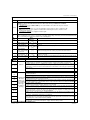
INVERTER PARAMETERS
Parameter display:
At the start-up the inveter enters the monitor mode: the d MENU is active, which allows to read the values acquired by the different
unit of measures, as stated in the table; first, the output frequency parameter is displayed. The same action is obtained by selecting the d MENU via the M key.
CODE
DESCRIPTION
CHANGE RANGE
UNIT
RANGE
MEASUREMENT UNIT
0.1
Hz
0.1
Hz
d-02 output current (rms)
0.1
A
d - 0 3 output voltage (rms)
1
V
1
V
d - 0 0 output frequency
d - 0 1 reference frequency
Fmin.to Fmax.
d - 0 4 continuous voltage (dc)
d - 0 5 output speed
(d-00)*(P-16)
0.01 /0,1/ 1
d - 0 6 reference speed
(d-01)*(P-16)
0.01 /0,1/ 1
d-07 cos ϕ
0.01
d-08 power
0.01
kW
d-09 inverter overload (100% = alarm threshold)
0.1
%
d-10 motor overload (100% = alarm threshold)
0.1
%
d - 1 1 braking resistance overload (100% = alarm threshold)
0.1
%
d - 1 2 last alarm memory
d - 1 3 second to last alarm memory
to reset the alarms use the C-03
d-14third to last alarm memory
control
d - 1 5 fourth to last alarm memory
d - 1 6 digital input state
11 11 11 11
d - 1 7 digital output state
d-1816bit parallel port state
d - 1 9 encoder pulses (updating time)
1/10
d - 2 0 encoder frequency
d - 2 1 encoder speed
each vertical segment
corresponds to an input or
output state, as shown in the
table on next page
0,1
(d-20)*(d-16)
Hz
0,01/0,1/1
d - 2 2 pid reference
0.1
%
d - 2 3 pid feedback
0.1
%
d - 2 4 pid error
0.1
%
d - 2 5 pid integral component
0.1
%
d - 2 6 pid output
0.1
%
0.1
A
d - 2 7 inverter rated current
d - 2 8 software version
d - 2 9 identification code( config. file)
d - 3 0 display test
20-GB - User
xx.xx
xxxx
all segments lit
STMDRIVE
INVERTER PARAMETERS
I/o digital state
DESCRIPTION
CODE
CHANGE RANGE
d-31 software type (related to d-28)
UNIT
RANGE
MEASUREMENT UNIT
xx.xx
d-32 not used
/
d-33 identification file code of parameters configuration
xxxx
d-34 identification file code of regulation configuration
xxxx
d-35 identification code of power size
xx
d-36 internal device temperature
1
°C
NOTE.: Each segment, when lit, indicates that the corresponding input or output are active
- Input:
11 11 11 11
REV
RUN
EXTFLT
IN 5
IN 4
not used
not used
not used
- Output:
11 11
not used
OUT 3
not used
OUT 1
STMDRIVE
User Manual - 21-GB
INVERTER PARAMETERS
Parameters quick guide (F menu, C menu)
F menu: it sets and/or reads the frequencies that can be selected through the terminal board
CODE
DESCRIPTION
F - 0 0 Reference frequency 0
CHANGE RANGE
UNITÀ
0,0 / 500,0
0,1 Hz
PRESET VALUE
0,0
PAG
28
F-01
Reference frequency 1
"
"
"
"
"
"
"
F-02
Reference frequency 2
"
"
"
"
"
"
"
F-03
Reference frequency 3
"
"
"
"
"
"
"
F-04
Reference frequency 4
"
"
"
"
"
"
"
F-05
Reference frequency 5
" "
"
"
"
"
"
F-06
Reference frequency 6
"
"
"
"
"
"
"
F-07
Reference frequency 7
"
"
"
"
"
"
"
F-08
Jogging frequency
"
"
"
"
1.0
32
C menu: it sets and executes some controls: to execute them, select value 7 and confirm via E.
CODE
PERFORMED ACTION
C - 0 0 Permanent storage of all parameters
C - 0 1 Recall of previously stored parameters
(*)
(the currently used parameters are replaced by the previously stored ones)
(*)
C - 0 2 Recall of the factory-set parameters (the storage depends on the operator's choice)
C - 0 3 Zero setting of the alarm memory
(*)
C - 0 4 Recall and storage of the parameters contained in the external programming key [from key to Inv.]
(*)
C - 0 5 Storage of the inverter parameters on the external programming key [from Inv. to key]
C - 0 6 Measure of motor phase resistance and corresponding initialization of parameter P - 12 (page 23) (FOXPM)(*)
(FOXPM) : parameter available in the FOXPM version
Caution: all parameters or part of them can be write-protected through P - 19 parameter;
In case of a non-authorized modification attempt or with a running motor, the following message will be
displayed: Prot.
NOTE: All parameters, which are not listed in the tables, are reserved for future developments; as a
consequence, they must be always set to 0.
PARAMETER
P-19
P-19
P-19
P-19
VAL
0
1
2
3
PERFORMED ACTION
no protection
F non-protected parameters, the others are protected
all parameters are protected
no protection; storage possibility with running motor too; not recommended
NOTE: The sign (*) means that the controls can not be executed with running motor
For safety reasons the P parameters, which can be changed, are divided into three groups or levels. Whether the parameters of
a given level (accessibility) can be changed or not depends on the presetting of the P-20 parameter:
P-20=1 →
1st level (factory setting)
P-20=2 →
2nd level
P-20=3 →
3rd level
22-GB - User
STMDRIVE
INVERTER PARAMETERS
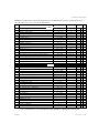
P menu: it sets all the values of the inverter parameters; they are divided into three groups or LEVELS; their access
depends on the code ( 1, 2, 3 ) set via the P - 20 parameter.
CODE
DESCRIPTION
RANGE
UNIT
PR
E S E T
VALUE
PAGE
Level 1
P - 0 0 reference setting
P - 0 1 maximum frequency
P - 0 2 maximum output voltage
P - 0 3 V/F characteristic type
P - 0 4 torque boost at low revolutions (boost)
P - 0 5 acceleration time 1
P - 0 6 deceleration time 1
P - 0 7 "S" curve characteristic ( S )
P - 0 8 modulation frequency
P - 0 9 motor rated current
P - 1 0 motor thermal constant
P - 1 1 rating of motor cos ϕ
P - 1 2 motor stator resistance
P - 1 3 motor efficiency
P - 1 4 min. frequency (offset) for frequency analog reference
P - 1 5 gain for frequency analog reference
( *** )
P - 1 6 conversion constant
P - 1 7 display message setting at start-up (value of d-xx)
P - 1 9 parameter protection code
P - 2 0 programming level
P - 2 1 acceleration time 2
P - 2 2 deceleration time2
P - 2 3 acceleration time 3
P - 2 4 deceleration time 3
P - 2 5 acceleration time 4 / jogging accel. time
P - 2 6 deceleration time 4 / jogging decel. time
P - 2 7 resolution for accel. / decel. ramps
P - 2 8 DC braking level
P - 2 9 frequency for DC braking enabling
P - 3 0 DC braking time at start
P - 3 1 DC braking time at stop
P - 3 2 slip compensation
P - 3 3 time constant of slip compensation
P - 3 4 jump frequency 1
P - 3 5 jump frequency 2
P - 3 6 jump amplitude
P - 3 7 output frequency upper limit
P - 3 8 output frequency lower limit
P - 3 9 parameter not used
P - 4 0 parameter not used
P - 4 1 parameter not used
P - 4 2 IN4 input configuration
P - 4 3 IN5 input configuration
Level 2
0
0-5;9
1
50.0 - 500.0
0.01/0.1 Hz
(P-72) - (**)
1V
(**)
(*)
31
(*)
"
28
50.0 (*)
"
0-4
1
1
0 - 30
1% di (P-02)
3
"
0.01 - 9999
0.01 / 0.1 / 1 s
5.0
32
0.01 - 9999
0.01 / 0.1 / 1 s
5.0
"
0.0 - 10.0
0.1 s
0,0
0 - (**)
1
(**)
(20% -150%)Inom
0.1 A
Inom
33
"
"
(*)
1 - 120
1 min.
20
"
0.01 - 1.00
0.01
(**)
"
0.0 - 99.99
0.01 ohm
0,0
"
0 - 100%
1
100
"
-500 /+500
0,1 / 1 Hz
0
29
0.000 - 9.999
0.001
1.000
"
0.01 - 99.99
0.01
1.00
20
0 - 36
1
0
0-3
1
0
1-3
1
1
0.01 - 9999
0.01 / 0.1 / 1 s
5.0
32
0.01 - 9999
0.01 / 0.1 / 1 s
5.0
"
0.01 - 9999
0.01 / 0.1 / 1 s
5.0
"
0.01 - 9999
0.01 / 0.1 / 1 s
5.0
"
0.01 - 9999
0.01 / 0.1 / 1 s
5.0
"
0.01 - 9999
0.01 / 0.1 / 1 s
5.0
"
0=0.01 1=0.1 2=1
1s
1
"
0 - 100
1%
0
38
0.0 / 500.0
0.1 Hz
0.0
"
0.0 - 60.0
0.1 s
0.0
"
0.0 - 60.0
0.1 s
0.0
"
0.0 - 25.0
0.1 %
0.0
34
0.0 - 10.0
0.1 s
0.1
"
0.0 / 500.0
0.1 Hz
0.0
32
0.0 / 500.0
0.1 Hz
0.0
"
0.0 - 100.0
0.1 Hz
0.0
"
(P-38) + 1
1% di (P-01)
100
"
0 - (P-37)
(P37) -1
0
"
0 - 17
1
4
28/35
0 - 17
1
0
"
NOTE: ( * ) the controls can be executed with stopped motor only ( ** ) the parameter values depend on the inverter size
( *** ) the coefficient allows to convert the frequency displayed in d-00 into output speed for P-05 and P06
STMDRIVE
User Manual - 23-GB
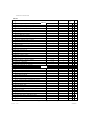
INVERTER PARAMETERS
P menu:
CODE
DESCRIPTION
P
UNIT
RANGE
R E S E T
VALUE
PAGE
Level 2
P - 4 4 OUT-1: output configuration (relais)
P - 4 5 parameter not used
P - 4 6 analog output 3 configuration (OUT3)
P - 4 7 IN-analog : analog input configuration
P - 4 8 analog output configuration
P - 4 9 analog output offset
P - 5 0 analog output gain
P - 5 1 analog output time constant
P - 5 2 max. amplitude of frequency correction by AUX-V
P - 5 3 signalling frequency
P - 5 4 hysteresis amplitude related to P-53
P - 5 5 current limit for overload
P - 5 6 delay time for overload signalling
P - 5 7 autoreset time
P - 5 8 number of autoreset attempts
P - 5 9 encoder updating time
P - 6 0 encoder pulses per Hz
P - 6 1 multiply factor related to P-60
P - 6 2 ohmic value of the braking resistance
P - 6 3 braking resistance power
P - 6 4 braking resistance thermic constant
P - 6 5 input setting by serial line enabling
P - 6 6 output setting by serial line enabling
P - 6 7 serial line configuration
P - 6 8 serial line address
P - 6 9 response delay time on serial line
Level 3
P - 7 0 basic frequency
P - 7 1 V / F intermediate frequency
P - 7 2 V / F intermediate voltage
P - 7 3 ramp start/stop frequency
P - 7 4 output voltage reduction
P - 7 5 undervoltage threshold
P - 7 6 max. time of short mains blackout
P - 7 7 accel. (if b-35=1in dec.) current limit for f<f_base
P - 7 8 accel. (if b-35=1in dec.) current limit for f>f_base
P - 7 9 current limit at constant speed
P - 8 0 current limit for motor pickup
P - 8 1 demagnetization time
P - 8 2 decel. speed to prevent stall at constant speed
P - 8 3 frequency scan time during motor pickup
P - 8 4 voltage reset time
P - 8 5 tolerance at constant speed
P - 8 6 ramp end delay/constant speed
P - 8 7 compensation gain of magnetizing current
p - 8 8 magnetiz. current compens. time constant
p - 8 9 reception time out ( serial communication ) [off if 0,0]
0 - 39
1
2
(*)
36
5
(*)
36
0 - 14
1
0
(*)
39
0 - 30
1
0
(*)
37
-9.99 / +9.99
0.01 V
0.00
"
-9.99 / +9.99
0.01
1.00
"
0.00 - 2.50
0.01 s
0.00
"
0 - 100
1% di (P-01)
0
"
0.0 - 500.0
0.1 Hz
0.0
36
0-39
0.0 - 100.0
0.1 Hz
0.5
"
20 - (**)
1%(mot.)
110
36
0.1 - 25.0
0.1 s
0.1
34
0.1 - 60.0
0.1 s
5.0
42
1 - 250
1
1
"
0.0(=0.01)-25.0
0.1s
0,1
36
"
1 - 9999
1
100
0.01 - 99.99
0.01
1.00
"
1 - 250
1 ohm
(**)
36
0 - 25.00
0.01 Kw
(**)
"
5 - 1250
5s
(**)
"
0 - 255
1
0
36
0 - 15
1
0
"
0 - 19
1
1
44
"
0 - 99
1
0
0 - 250
1 ms
1
(P-71) - 500.0
0.1 Hz
50.0
(*)
31
0 - (P-70)
0.1 Hz
25.0
(*)
"
0 - (P-02)
1V
(**)
(*)
"
0 - 25.0
0.1 Hz
0.0
(*)
"
0 - 100
1%(P02)
100
40 - 80
1%(P02)
50
(*)
34
(*)
"
"
"
0.1 - 25.0
0.1 s
1.0
20 - 150
1%(Inom)
150
33
20 - 150
1%(Inom)
150
"
20 - 150
1%(Inom)
150
"
20 - 150
1%(Inom)
150
34
0.01 - 10.00
0.01 s
(**)
"
0.1 - 25.0
0.1 s
1.0
33
0.1 - 25.0
0.1 s
1.0
34
0.1 - 25.0
0.1 s
0.2
31/34
0.1 - 25.0
0.1 Hz
0.5
33
0.1 - 25.0
0.1 s
1.0
"
0 - 100
1
0
0-3
1
0
0.0 - 25.0
0.1
0.0
44
NB. : ( * ) the controls can be executed with stopped motor only; ( ** ) the values depend on the inverter size.
24-GB - User
STMDRIVE
INVERTER PARAMETERS
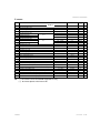
P menu:
CODE
P - 9 0 PID reference
P-91 PID max. positive error
P-92 PID max. negative error
P-93 PID updating time
P-94 proportional term gain
P-95 integral action time
P-96 derivative action time
P-97 proportional term gain
P-98 integral action time
P-99 derivative action time
P-100 parameter not used
P-101 parameter not used
P-102 parameter not used
P-103 parameter not used
P-104 REV-V analog input offset
P-105 REV-V analog input gain
P-106 AUX-V analog input offset
P-107 AUX-V analog input gain
P-108 parameter not used
P-109 parameter not used
P-110 inverter nominal input voltage
P-111
P-112
P-113
P-114
P-115
P-116
P-117
PRESET
RANGE
UNIT
0,0 - 100,0
0,1 %
0,0
40
0,1 - 100,0
0,1 %
5,0
"
0,1 - 100,0
0,1 %
5,0
"
0,00(=0,005) - 2,50
0,01 s
0,00
"
0,00 - 99,99
0,01
0,00
"
0,00 - 99,99
0,01
99,99
"
0,00 - 99,99
0,01
0,00
"
0,00 - 99,99
0,01
0,00
"
0,00 - 99,99
0,01
99,99
"
0,00 - 99,99
0,01
0,00
"
-9,99 / +9,99
0,01V
0,00
29
-9,99 / +9,99
0,01
1,00
"
-9,99 / +9,99
0,01V
0,00
"
-9.99 / +9,99
0,01
1,00
"
1V
DESCRIPTION
VALUE
PAG
Livello 3
set 1
set 2
TOP deceleration time (3-wire control commands)
110-220-380-460
0,00 a 9999
mask of direction rotation (3-wire control commands)
0 a 255
( **) (*)
31
0,01/01/1s
0,0
30
1
0
"
0
37
automatic DC braking level
0 a 100,0
1% P02
automatic DC braking frequency level enabling
0,0 a 50,0
0,1Hz
0,0
30/37
P-114 hysterisis
0,1 a 25,0
0,1Hz
0,2
37
acceleration time of DC braking output
0,01 a 250
0,01/01/1s
0,1
"
deceleration time of DC braking input
0,01 a 250
0,01/01/1s
0,1
"
NB. : ( * ) the controls can be executed with stopped motor only;
( ** ) the values depend on the inverter size.
STMDRIVE
User Manual - 25-GB
INVERTER PARAMETERS
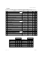
b menu:
It sets the values of ON / OFF parameters; they are divided into three groups, or LEVELS, access to which depends on
the code ( 1, 2, 3 ) set via the P - 20 parameter. They all can be modified with stopped motor only
CODE
DESCRIPTION
RANGE
b - 0 0 run/reversal input configuration
b - 0 1 stop mode
b - 0 2 reversal enabling
b - 0 3 protection
b - 0 4 reference input reversal (input max ⇒ output min)
b - 0 5 current input
b - 0 6 enabling of motor overload protection
b - 0 7 motor type
b - 0 8 configuration of external alarm input
b - 0 9 external alarm tripping mode
P
UNIT
R E S E T
VALUE
PAGE
Level 1
0=RUN/REV
1=FWD/REV
0
27
0=in ramp
1=coast
0
30/35
0=off
1=on
1
"
0=off
1=on
1
30/29
25/29
0=off
1=on
0
0=0/20mA
1=4/20mA
1
"
0=off
1=on
1
25/29
0=standard
1=servoventilated
0
"
0=NO(nor. open)
1=NC(nor.closed)
0
35
0=alarm/lock
1=inverter disabl.
0
"
0=always
1=run only
0
"
0=off
1=on
0
35
0=off
1=on
0
30/35
0=off
1=on
0
35
0=off
1=on (10 min.)
0
"
0=off
1=on
1
35
0=always
1=con. sp. only
0
26
0=off
1=on
0
29
0=always
1=con. sp. only
0
"
0=off
1=on
0
"
0=off
1=on
0
36
0=off
1=on
1=on
0
0
36
0=off
0=off
1=on
0
34/36
0=off
1=on
1
36
b - 2 5 stall prevention at constant speed
0=off
1=on
1
"
b - 2 6 stall prevention during deceleration
b - 2 7 overvoltage prevention
0=off
1=on
1
"
0=off
1=on
0
"
b - 1 0 external alarm detection mode
Level 2
b - 1 1 autoreset handling in case of external alarm
b - 1 2 autoreset enabling
b - 1 3 enabling of autoreset attempt limitation
b - 1 4 enabling of autoreset of auto zero-setting attempts
b - 1 5 autoreset alarm contact
b - 1 6 voltage reduction tripping mode
b - 1 7 enabling of momentary overload control
b - 1 8 tripping mode of momentary overload control
b - 1 9 enabling of momentary overload alarm
b - 2 0 enabling of braking resistance overload protection
b - 2 1 encoder enabling
b - 2 2 encoder channels configuration
b - 2 3 encoder input used as flying restart
b - 2 4 stall prevention during acceleration
/ not used
AUX-V
REF--V
REF--I
current
torque
power
set to 0
26-GB - User
Level 3
feedback switches
reference switches
b-55 b-54 b-53
0
0
1
0
1
0
0
1
1
0
1
0
1
1
0
0
1
1
1
1
1
0
0
0
b - 5 2b - 5 1 b - 5 0
0
0
0
0
1
0
0
1
0
1
0
1
0
0
1
0
1
1
1
0
1
1
1
1
ref. frequency
/ not used
AUX-V
REF--V
REF--I
parameter P-90
freq. after ramp
generator
set to 0
STMDRIVE
INVERTER PARAMETERS
b MENU:
PRESET
UNIT
RANGE
DESCRIPTION
CODE
PAGE
VALUE
Level 3
0=off
1=on
0
34
0=off
1=on
0
"
0=freq. reference
1=freq. max
0
"
0=off
1=on
0
"
0=off
1=on
1
33
0=off
1=on
1
33
0=off
1=on
0
33
0=off
1=on
1
33
0=off
1=on
0
33
0=off
1=on
1
34
b-38 overmodulation (torque increase)
0=off
1=on
0
b-39 terminal board control enabling
b-40 PID regulator enabling
b-41 regulator tripping mode
b - 4 2 enabling encoder synchronizing / PID
b-43 variable adjusted by PID regulator
b-44 error sign reversal
b-45 adjustment mode
b-46 suppression of PID regulator positive output
b-47 suppression of PID regulator negative output
b-48 suppression of positive or negative integral term
b-49 integral term initialization at start
b-50
0=off
1=on
1
35/43
0=off
1=on
0
40
0= running
1= running speed cost.
0
"
0=off
1=on
0
40
0=frequecy
1=voltage
0
40
0=off
1=on
0
"
0=direct
1=sum (feed/forw.)
0
"
0=off
1=on
0
"
0=off
1=on
0
"
0=off
1=on
0
"
0=off
1=on
0
"
b - 2 8 prevention of short mains blackout
b-29 motor pickup enabling (flying restart)
b-30 scan start frequency for pickup control
b-31 motor pickup at start-up
b-32 automatic adjustment of output voltage
b-33 dead times compensation
b-34 automatic boost enabling
b - 3 5 stall prevention to overload in deceleration
b-36 enabling of switching frequency reduction under 5 Hz
b-37 enabling of undervoltage alarm storage
b-51
PID reference input switches
see following table
40/41
PID feedback input switches
see following table
40/41
b-52
b-53
b-54
b-55
b-56 reserved
0=allarm active
1=active withoout allarm
0
b-58 serial line termination
0=no character
1=automatic enabling
0
43
b-59 display menu modality
0=display menu
1=motorpot. menu
0
28
0=not enabled after jog
1=enabled after jog
0
38
0=normal compensation
1=advanced comensation
1
32
0
40
b-57 configuration of the logic allarm relais
b-60 DC braking based on JOG function
b-61 reserved
b-62 dead time compensation
b-63 PID reverse rotation enabling
b-64 overtemperature prevention at low speed
0=foward rotation with pid neg. 1= reverse rotation with pid neg.
0=disabled
1=enabled
1
b-65 derivative PID selection
0=error calculated
1= feedback calculated
0
b-66 current clamp enabling
0=disabled
1=enabled
1
b-67 3-wire control command enabling
0=off
1=on
0
28
b-68 automatic DC braking enabling
0=off
1=on
0
0= continuous
1=discontinuous
1
37
32
b - 6 9 modulation type
STMDRIVE
40
User Manual - 27-GB
INVERTER PARAMETERS
Function description:
Frequency reference
PARA
FUNCTION
METER
Determines the
P - 0 0 inverter operation
frequency
RANGE
[ DEFAULT]
0 - 5; 9
[0]
the values 6,7,8
are not used
Indicates the
max. operation
P - 0 1 frequency
50.0 - 500.0
[ 50,0 ] (Hz)
VA
LU
ES
DESCRIPTION
ASSOCIATED
PARAMETERS
Each parameter value correspond to a different reference:
0 analog input: REF-V (0/10V with J4 not inserted)
1 analog input: REF-V (-/+10V with J4 not inserted)
2 analog input: REF-AUX with J4 inserted (0/20mA [b-05=0] or 4/20mA
[b-05=1] )
3 it selects the frequency set by the F-00 parameter
4 input from serial line with 0.01 Hz resolution
5 encoder input (only with option OPZ-ENC)
9 motorized potentiometer reference
P-01
P-14
P-15
b-04
The set value is the full scale value for the analog inputs and for
the variables of the F menu.
Digital input reference
By configuring the two digital inputs as frequency switches (P-42=1 and P-43=2), it is possible to recall the frequencies set
via the F parameters:
INPUT
In 4
0
1
0
1
DESCRIPTION
In 5
0
0
1
1
la frequenza di riferimento è letta secondo
the frequency reference is the frequency
the frequency reference is the frequency
the frequency reference is the frequency
P00
F-01
F-02
F-03
NOTE:
in the table: 1 = means closed contact,
0 = means open contact;
a non-used input is
considered as 0.
Motorpotentiometer reference by keypad
As alternative of digital/analog input reference can be selected the Motorpotentiometer function, increasing and decreasing the
frequency reference by the using of up and down bottoms on the drive keypad.
Follow the procedure below to enable the function:
-
Set P00=9 (frequency reference through motorpotentiometer)
-
Access to "Mt" menu pushing "M" bottom
-
Increase and decrease the frequency reference through ⇑, ⇓ bottoms. This function allows to storage the reference step, sets
by the user before the drive power-off.
-
Optional: with b59=1 the motorpotentiometer menu, "Mt", will be displayed at drive power on.
N.B. For the function of the motor potentiometer it's need the looking command running (RUN: terminal 2).
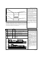
Main analog input reference: REF-V
When the analog input REF-V is selected (voltage or current), it is possible to manage its signal through the following parameters:
P-104
P-105
P-106
P-107
analog input REF-V offset (positive or negative values)
analog input REF-V gain (positive or negative values)
analog input AUX-V offset (positive or negative values)
analog input AUX-V gain (positive or negative values)
P105>1
F rif
P105=1
Frif = ( ( P01 - P104) * P105) * Vrif
10
P01
P105<1
In case of negative input voltage the motor rotation
assumes negative sign.
P104
0
28-GB - User
10
V
STMDRIVE
INVERTER PARAMETERS
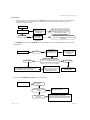
MAIN REFERENCE SELECTION DRAWING:
0/10V
+/-10V
P-00
J4
18
REF-V
ABS(x)
P-104
P-105
0/10V O
+/-10V
0
FREQUENZA DI
P-14
P-15
b-04
1
0-20mA
RIFERIMENTO
2
+/-10V
0/10V
0-20mA
J11
16
REF-AUX
P-106
P-107
b-05
4-20mA
0/10V o +/-10V
0-20mA
P-47
When the analog input REF-V or REF-AUX (voltage or current) are selected, it is possible to manage through the following formula
the frequency input signal (P-104, P-105, P-106, P-107 parameters):
P-14
P-15
b-04
determines the minimum frequency (offset); it can assume negative values too.
it is a gain multiplicative factor G= P15* (P01-P14)/10.
enables the formula reversal (a minimum signal corresponds to a maximum frequency).
Example: with P-00 = 1 the reference is the voltage analog signal type -10/+10 V:
Direct formula: b-04=0 with P14 > 0
F rif
Inverse formula: b-04=1
F rif
P01
P15=1
P15>1
with P14 > 0
P01
P15<1
P15<1
P15>1
P14
P14
0
10
0
V
Frif = P14 + ( ( P01 - P14 ) * P15 ) * Vrif
10
Direct formula: b-04=0 with P14 < 0
10 V
Vrif = 10 / P15
Frif = P01- (
Inverse formula: b-04=1
P15=1
( P01 - P14 )
* P15) * Vrif
10
with P14 < 0
F rif
F rif
P15>1
P15=1
P01
P01
P15<1
0
P14
10
V
P14
0
10
V
Vrif (f=0) = 10 / P15
Vrif (f=P01) =
(P14/(P14-P01)) * (10 / P15)
Vrif (f=0) = (10 / P15) * ( P14 / (P14 - P01 ))
Frif = ( P01- P14 ) - ( ( P01 - P14 ) * P15) * Vrif
10
In any case Frif is always limited between P-73 and P-01.
STMDRIVE
User Manual - 29-GB
3-wire control commands function
This function can be activade by B-67 = 1.
It allows to give Run command and select one of the frequency steps programmed with F-01 - F-07 and P-112, only if 3-wire control
commands enabled.
REV, RUN and IN5 inputs become frequency selectors (positive/negative direction) according to the following table:
Terminals
RUN
off
off
on
on
off
off
on
on
REV
off
off
off
off
on
on
on
on
IN5
off
on
off
on
off
on
off
on
Reference
Function
F-01
F-02
F–03
F–04
F–05
F–06
F–07
STOP
RUN – direction bit1 of P-112
RUN – direction bit2 of P-112
RUN – direction bit3 of P-112
RUN – direction bit4 of P-112
RUN – direction bit5 of P-112
RUN – direction bit6 of P-112
RUN – direction bit7 of P-112
"ON" means contact closed; "OFF" means contact open
For Run command activation, it is necessary to give one of 3 input; the selection of frequency step programmed depends by the
combination of 3 inputs control.
P-112 parameter determines the frequency sign, so the motor direction. It is a 8 bit value, where each bit assumes a digital frequency
step: 0 means forward direction and 1 means reverse direction.
P-112
Posizione
F associata
Peso
bit7
F-07
128
bit6
F-06
64
bit5
F-05
32
bit4
F-04
16
bit3
F-03
8
bit2
F-02
4
bit1
F-01
2
bit0
1
To calculate P-112 parameter value, it is necessary to sum each bit value that has been set to 1.
Example: if it is necessary to use F-01 and F-05 as REV direction and all the others as FWD: bit 1 and bit 5 of P-112 must set to 1;
all the others must be set to 0.
P-112 value will be 2 + 32 = 34 (sum of F-01 and F-05 values).
P-112 defult value is 0; it means FWD direction for all the digital frequency reference.
From STOP to RUN and during multi frequencies selection are executed the standard acceleration/deceleration ramps; from RUN
to STOP (when there are not any command applied to the terminals) the deceleration ramp is determined by P-111 parameter.
If P-111 is 0 (default) the deceleration ramp is not executed; the motor will coast to stop.
VALUE
DESCRIPTION
[ DEFAULT]
P - 1 1 1 stop deceleration time 0,00 / 9999 RUN/STOP deceleration time of 3-wire commands control
[ 0s ]
0 /255,0
3-wire commands control frequency mask of direction rotation
P-112 mask of direction
[0]
(positive/negative directions)
rotation
PARA
METER
FUNCTION
b - 6 7 3-wire
commands
control enabling
0 /1
[0]
0 = disabled
1 = enabled
.
30-GB - User
STMDRIVE
INVERTER PARAMETERS
V / F characteristic
PARA
P - 0 3 Determines the
voltage to be applied to the motor as a function
of the frequency
PARA
P - 7 0 To customize the characteristic:
P - 7 1 the change is possible only if P-03 = 0
P-72
P - 0 2 Selects the max. voltage applied to the
motor. Rating value of
ASSOCIATED
DESCRIPTIION
PARAMETERS
Each parameter value correspond to a
different characteristic:
0 user-defined characteristic
1
2
3
4
FUNCTION
METER
VA
LUE
RANGE
[ DEFAULT]
0-4
[1]
FUNCTION
METER
RANGE
[ DEFAULT]
(P-71) - 500.0
[ 50.0 ]
(Hz)
0 - (P-70)
[ 25.0 ]
(Hz)
0 - (P-02)
[ (**) ]
(V)
(P-72) - (**) (V)
[ (**) ]
the motor V.
linear characteristic for 50 Hz motors
linear characteristic for 60 Hz motors
quadratic characteristic for 50 Hz motors
quadratic characteristic for 60 Hz motors
P-02
P-73
P-04 P-70 P-71 P-72
P-74 P-84 b-16 b-32
P-02
b-16
P-04
b-32
P-73 P-74 P-84
DESCRIPTION
Selects the motor base frequency (rated); this frequency is associated to the
motor max. voltage (max. V set via P-02 and P74) .
Selects the intermediate frequency.
Selects the voltage applied to the motor as regards the intermediate
frequency.
To make this value independent from the inverter supply voltage fluctuation
enable the automatic adjustement function of the output voltage by setting b32=1. In this case, the inverter can be supplied through a voltage higher than the
motor rated one. If b-32=0 then the voltage value set by P-02 must match the
motor rated voltage.
110-220-380-460 Select the choice between nominal input voltage expected. Automatic setted
D27,P02, P09, P72 in function of nominal voltage.
(V)
P - 1 1 0 Inverter nominal
input voltage
P - 0 4 Increases the output voltage at 0 Hz
(% of P-02) and the
torque.
P - 7 3 Selects the freq. ap-
plied to the motor at
start.
The set voltage increase is added to the V/F characteristic in a decreasing
way, until it is annulled at F= Fintermedia. (figure A)
0 - 30
[3]
It is the ramp begin frequency at the start and the ramp end frequency at the
stop.
0 - 25.0
[ 0.0 ]
(Hz)
P - 7 4 Limits the voltage applied
The max. output voltage is limited to the value (P-74*P-02)/100.
0 - 100
[ 100 ]
to the motor(% of P-02).
Controls the voltage
0=always;
b - 1 6 reduction set by P-74 1=con. speed only
parameter.
[0]
States the max. spe- 0.1 - 25.0
(s)
ed
of
voltage
change
P-84
[ 0.2 ]
If b-16=0 the reduction is always active; if b-16=1 the reduction is not active during
the ramps, so that the torque is completely available both in acceleration and
deceleration state (figure B)
Time needed to go from 0% to 100% of V and viceversa
NOTE : too short times cause excessive current peaks.
[ (**) ] = The default value depends on the inverter size.
P-03=3
P-03=1
P-02
V
P-02
P-03=4
V
P-02
P-02
V
(P-02)/2
(P-02)/2
(P-72)
(P-02)/4
(P-02)/4
25
(P-71)
Fig.A
P-03=2
V
25
50 f
(P-70)
50
f
Fig.B
V
P-02
30
100%
60 f
60 f
30
V
P-74
P-72
f
→ P-84 ←
t
P-04
P-71
STMDRIVE
P-70
f
t
User Manual - 31-GB
INVERTER PARAMETERS
Freq. jumps - Output freq. limitations - Jogging - Switching freq. - Accel./decel. ramps
PARA
FUNCTION
METER
P - 3 4 Jump frequency N.
1
P - 3 5 Jump frequency N.
2
Frequency interval
P - 3 6 ∆f on the left or right
of
the
frequency
jump
RANGE
[ DEFAULT]
0.0 - 500.0
[ 0.0 ]
(Hz)
0.0 - 500.0
[ 0.0 ]
(Hz)
0.0 - 100.0
[ 0.0 ]
(Hz)
DESCRIPTION
Particular inverter frequencies can cause mechanical vibrations.
The parameters P-34 P-35 and P-36 set two frequency bands which are crossed
during the ramp phase but which can not be accepted as a normal frequency.
If Fref decreases inside a prohibited area, the inverter uses a frequency set at the
limit of the area defined via P-36.
Ex.: the interval of the N.1 freq. goes from (P-34)-(P-36) to (P-34)+(P-36).
To disable an interval set at 0 Hz the frequency of P-34 or P-35
The two intervals can overlap.
Upper limit of the (P-38) + 1 / 1% di The output frequency can be limited independently of the maximum and
P - 3 7 output frequency (%
minimum values defined by parameters P-01 and P-14.
(P-01) [ 100 ]
of P-01)
Lower limit of the 0 - (P-37) / (P-37) - The output frequency can exceed the maximum frequency set by P-01 up to
the max. value of 110%. This is done by using the slip compensation function
output
frequency
(%
P-38
or the speed feedback with the PID regulator.
1[0]
of P-01)
Selects the seb - 0 0 quence followed
by the RUN and
REV togheter
with the input IxJOG
P - 0 8 Switching freq.
selection (executable with stopped motor only)
b - 3 3 Dead time comp.
b - 6 2 Dead time
compensation
of
b - 6 9 Optimization
high frequency
b - 3 6 commutation
Overtemperature
b - 6 4 prevention at low
speed
0 = off - 1 = on
[0]
0 - (**)
(**)
0 = 1kHz; 1 = 2 kHz; 2 = 3 kHz; 3 = 6 kHz; 4 = 9 kHz; 5 = 12 kHz; 6 = 15 kHz;
7 = 18 kHz.
0 = off - 1 = on
[1]
0 = off - 1 = on
[1]
Dead time compensation: it improves the torque and fluidity actions at low speed.
0 = off - 1 = on
[0]
0 = off - 1 = on
[0]
0 = off - 1 = on
[1]
P - 4 2 It configures the IN4
0-17
P - 4 3 They configure the
0-17
input
IN 5 input
JOGGING is a run control to advance the motor by small amounts. It applies
preset freq. to the motor via param. F-08 with acc. and dec. ramps set via param.
P-25, P-26. It does not allow DC current braking at startup or in stop condition
If b-00 = 0: RUN = run, REV = reversal, and the input Ix-JOG handles the
jogging control. If RUN and Ix-JOG are simult. enabled the first one enabled will
override the other one.If b-00 = 1: RUN = forward run, REV = backward run, the
Ix-JOG enables the jogging control that overrides the normal run control.
High values of the switching frequency reduce or eliminate the electric "noise"
generated by the motor; viceversa, low values give a higher rotation fluidity at
low speed, especially if high torques are required.
"0"
means standard dead time compensation; "1" means advanced dead time
compensation, which performs sinusoidal signal of output current at low speed rotation.
"0" means standard sinusoidal modulation; "1" means flat sinusoidal modulation,
which optimize the inverter heatsink temperature with high frequency commutation.
Frequency automatic commutation to 3 kHz, when output frequency goes below 5 Hz.
"1" means overtemperature prevention at low speed rotation; the inverter will have in
general a better efficiency, fluid motor rotation and low electromagnetic emission.
In order to use IN 4 and IN 5 as ramp selectors, P-42 and P-43 must acquire the
value 5 (selector In T1) and 6 (selector In T2).
The input state combined to the selectors In T1 In T2 defines one of the four possible
ramp couples
DESCRIPTION
In T1 In T2
0
0 accel./decel.ramp 1 (P05 = accel. time -P06 = decel. time)
1
0 accel./decel. ramp 2 (P21 = accel.time -P22 = decel. time)
0
1 accel./decel. ramp 3 (P23 = accel. time -P24 = decel. time)
1 accel./decel. ramp 4 (P25 = accel. time -P26 = decel. time)
It selects the reso- 0 = 0.01 s - 99.99 s 1
P - 2 7 lution through whi- 1 = 0.1 s - 999.9 s
ch the ramp times 2 = 1
s - 9999 s Note: a) 1= closed contact; the controls not used are considered in 0 state.
b) When the jogging control Ix-JOG is active (page 28), the ramp pair 4 is
are defined
[1]
automatically chosen. The acceleration and deceleration times are necessary to
switch from zero Hz to the max. frequency, (P-01), and viceversa.
c) The modification of P-27 can affect the values entered on P-01, P-02,
P-21, P-22, P-23, P-24, P-25, P-26 so these values must be rechecked.
d) Connecting a signal 0/10V to the input REF-AUX the ramps can be lengthenned
in function (proportional) at the signal, with P-47; es. the ramp of 2 sec. and 8V of a
amplitude signal: 2(s)x8(v)=16s of lengthening.
e)The ramp extension can also be generated if the functions of motor stall
and inverter lock are enabled. This actuation is signaled by a flashing GREEN LED
and also on terminal board by properly programming OUT1.
P - 0 7 It selects the ramp 0.0 = linear
0.1s - 10.0 s=
form
" S " shaped ramp
( ** ) the values depend on the inverter size.
32-GB - User
STMDRIVE
INVERTER PARAMETERS
Motor data setting - Motor thermal protection - Prevention of motor stall - inverter lock
RANGE
[ DEFAULT]
P - 0 9 Motor rated current (20% - 150%) Inom.
( from the rating) (*)
[ Inom ]
(A)
1 - (120)
P - 1 0 Sets the motor
thermic constant (*)
[ 30 ]
(min)
0.01 - 1.00
P - 1 1 Motor cos ϕ (obtained
from the rating) (*)
[(**)]
P - 1 2 Equivalent stator
resistance (*)
0.0 - 25.0
PARA
DESCRIPTION
FUNCTION
METER
[(**)] (Ω)
To take advantage of the inverter/motor system features, it is necessary to set the
characteristics of the motor used, through the parameters.
P-10 can be calculated, (necessary only if the motor thermal protection function is
enabled, par. b-06). The higher the value set, the higher the motor capacity of supporting
currents higher than the rated one.
The value of P-12 represents the motor phase resistance in case of star connection,
or 1/3 of the phase resistance in case of delta connection. To get the proper value of
P-12, use the function C-06:
ON DISPLAY:
- 1) Use M to select the C menu .....................................
C-00
- 2) Use the ⇑, ⇓ keys to select the code C-06 .................. ON DISPLAY:
and press E:
the code C-06 is displayed .........................................
ON DISPLAY:
C-06
0
- 3) Use the ⇑, ⇓ keys to select the code 07
ON DISPLAY:
7
and press E:
the stator resistance is automatically measured.
The display will confirm that the operation has been executed .(To see the measured
value, read the value of P-12 that, if necessary, can be manually modified).
b-06
Enables the termal
protection of the motor (*)
B - 0 7 Standard or assisted
ventilation
Limits the acceleration
b - 2 4 current. (*)
Limits the current at
b - 2 5 constant speed. (*)
Limits the voltage dub - 2 6 ring deceleration.
Prevents overvoltage.
b - 2 7 (*)
b - 3 5 Stall prevention to
overload in decel.(*)
P - 7 7 The parameters set
the current threshold
P - 7 8 as a % of Inom (*)
0 = off - 1 = on
[1]
0 = standard
1=assisted
ventilation
0 = off - 1 = on
[1]
0 = off - 1 = on
[1]
0 = off - 1 = on
[1]
0 = off - 1 = on
[0]
0 = off - 1 = on
[1]
20 - 150
[ (150) ]
P-79
Set the deceleration
P - 8 2 ramp when b-25 is
0.1 - 25,0
[1]
( s)
P - 8 5 wich start the ramp
0.1 - 25,0
[ 0,5 ]
( Hz )
state.
Set the delay after wich
P - 8 6 the motor is considered in constant speed
state.
0.1 - 25,0
[ 0,1 ]
(s)
active (*)
Set max. ref. Df after
b-07=0 : motor natural ventilation (at low speed there is a derating of drive
nominal current).
b-07=1 : motor assisted ventilation. Both cases are considered by the drive
internal algorithm to calculate the overload.
The level reached by the protection can be read in d-10, measured in % of the max.
thermic overload allowed for the motor. When this level reaches 100%, the protection trips and the inverter is locked.
Excessive current or voltage can cause motor stall or inverter lock conditions due to
protections tripping.The aim of the parameter is to set thresholds that, when exceeded,
trip some actions that limit currents and voltages:
b-24: if the threshold programmed through P-77 (in acceleration state and if f<P-70,
constant torque zone), or through P-78 (in acceleration state and if f>P-70, constant
power zone) is exceeded, the ramp is stopped until the current remains over this
threshold.
b-25: if the threshold programmed through P-79 is exceeded (constant speed operation) the output frequency is reduced at a rate controlled by P-82; as soon as I falls below
the theshold the frequency start to increase with the selected ramp.
b-26: the ramp is stopped when the voltage on filter capacitors is near the overvoltage
threshold; when the V falls under the threshold the ramp starts again; NOTE: the function
can be unable to prevent the inverter lock in case of high-inertia loads and short ramps.
b-27: if the voltage on filter capacitors exceeds the overvoltage threshold, the output
voltage is set to zero (corresponding to a coast-to-stop). As soon as the voltage reaches
safety levels,a free rotation motor pickup is executed and the deceleration ramp is
restarted.
NOTE: too short ramps can lock the inverter by overvoltage.
The parameters allows to distinguish between the acceleration or deceleration state
and the constant speed state . In fact, too short accel. ramps asregards the motor
capacity, or slight reference variations, either intentional or not, does not mean the motor
to be considered in constant acceleration or deceleration. The switching from one state
to the other can be controlled through P-85, P-86: P-85 set the indifference range to
reference change as regards the constant speed; P-86, instead, set the time after
which, starting from ramp completion, the motor is in constant speed state.
(*) : parameter available in the FOXPM version; ( ** ) the values depend on the inverter size.
Inom
(P-09)
100%
Permanent current for a standard motor
( b-07=0 ).
50%
Permanent current of brake c.c. for a
standard motor.
(P-70)/2
STMDRIVE
(P-70)
f
User Manual - 33-GB
INVERTER PARAMETERS
Slip compensation - Instantaneous overload signalling - Prevention of short mains blackout Pickup of motor in free rotation (flying restart) - Automatic boost
PARA
FUNCTION
METER
P - 3 2 Defines value of the
motor rated slip (% )
s=(no-nnom)*100/no
P - 3 3 Compensation time
constant
RANGE
[ DEFAULT]
0.0 - 25.0
[ 0.0 ]
0.0 - 10.0
[ 0.1 ]
(s)
b - 1 7 Enable the overload
DESCRIPTION
The parameters compensate for the motor speed reduction when increasing the
applied load (slip), changing the inverter output frequency proportionally to the
applied load. Note: a too quick response (P-33 too short) can cause fluctuations
in the output frequency. To obtain a good compensation properly set P-09, P-11,
P-12 and if the reference frequency is close to the maximum frequency, it is
advisable to set on P-37 a value beyond 100%.
0 = off - 1 = on
detection function
[0]
b - 1 8 Select when the detec- 0=always - 1= con.
tion function is active
speed [ 0 ]
b - 1 9 Set the overload locked 0 = off - 1 = on
state
[0]
20 - 200
P - 5 5 Set the tripping level of
the protection
[ 110 ]
(%)
0.1 - 25.0
P - 5 6 Set the delay before
the protection trip
[ 0.1 ]
(s)
The aim of the function which detects the overload is to signal or avoid excessive efforts on the load, causing the istantaneous locking of the inverter and
the allarm signalling.
The threshold defined by P-55 is in % of the motor rated load as obtained
through parameters P-09, P-11.
The threshold exceeding can be signalled through terminal board by configuring the Ox-GTT output.
The parameter P-12 must be accurately set too.
P-56 Set how long the overload can exceed the tripping threshold before the
signalling and the inverter lock functions are enabled
b - 2 8 Enables the prevention
The parameters avoid locking the inverter when a short mains blackout
happens.The mains cut off is stated on the display and on the terminal board by
configuring one of digital outputs OUT1.
Note:on single phase inverter it is advisable to reduce the P-75 value to the
minimum to prevent excessive start-up currents. Otherwise it is possible that
the inverter locks by undervoltage.
The alarm is always enabled if the voltage falls under a given value that depends
on the inverter size; the tripping of the prevention function sets the output voltage
to zero, (coast-to-stop). In this way, the filter capacitors are not completely
discharged thus keeping the control logic active. As soon as the voltage exceeds
the threshold (hysteresis of 6%), a pickup phase of motor in free rotation is
performed, thus resetting the speed in force before the tripping.
of short mains blackout
0 = off - 1 = on
[0]
Determines the under-
P - 7 5 voltage protection tripping threshold
Set the max. duration of
short mains
blackout before the
alarm is enabled
P - 7 6 the
b - 2 9 Enables the tripping of
the motor pickup
b - 3 0 Selects the initial
scanning frequency
b - 3 1 Enables the function
with the first run control
after startup
P - 8 0 Sets the max. current
threshold during the
motor pickup phase
P - 8 1 Demagnetizing time
P - 8 3 Sets the rate of change
of the frequency during
the lock search
P - 8 4 Set the max. rate of
change of the voltage
b - 2 3 Enable the use of encoder for the function.
Enables the automa-
b - 3 4 tic boost.
34-GB - User
40 - 80
[ 50 ] (% di P-02)
0.1 - 25.0
[1]
(s)
0 = off - 1 = on
[0]
0=ref. freq.
1=max. freq.
[0]
0 = off - 1 = on
[0]
The aim of the pickup function of motor in free rotation is to avoid too high startup currents generated when, for some causes the inverter cuts the voltage to the
motor, then a subsequent run command makes a start from zero Hz with the
motor still rotating.
This function generates an initial frequency, b-30, equal to or higher than the
motor one, by gradually increasing, P-84, the output voltage to 100 % and
controlling that the current does not exceed a preset threshold set by P-80, (it is
advisable that this value should be slightly higher than the current absorbed by
20 - 150
the motor) otherwise the output frequency would be reduced and the voltage
[ 150 ] (% di Inom)
would be limited.
The delay between the cut off of the motor voltage and when the motor pickup
0.01 - 10.00
phase start can be controlled by P-81 (demagnetization time).
(s)
The motor is considered frequency-locked when a given frequency is reached so
0.1 - 25.0
that, at full voltage, the current is under the threshold.The motor can then be
[1]
(s)
accelerated or decelerated until the reference is reached.
b-23 enables the use of a frequency obtained from an encoder as initial fre0.1 - 25.0
quency for motor pickup.
[ 0.2 ]
(s)
The motor pickup function can be enabled through terminal board by configuring
one of the inputs as Ix-FLY input. If the Ix-FLY input is active, every time the run
0 = off - 1 = on
control is pressed the motor pickup is performed.
[0]
0 = off - 1 = on
[0]
This function is an alternative to the voltage (and torque) boost obtained through
parameter P-04 (pag. 23).The output voltage is automatically increased as
regards the motor and the connected load characteristics. The efficiency of the
action depends on the accuracy applied when setting the parameters P-09, P11, P-12.
If the programming phase is not performed in the right way, some oscillations may occur.
STMDRIVE
INVERTER PARAMETERS
Programmable and non-programmable control inputs
INPUT
FUNCTION
NAME
TERM.NO.
1
REV Se b-00=0 Run reversal
Se b-00=1 Back. run
For. run
Run
2
RUN
3
EXTFLT
Alarm coming from outside
5
IN5
4
IN4
Configurable digital inputs
DESCRIPTION
Terminals 1, 2, 3, have pre-defined functions; the
other five can be configured through parameter P42, P-43.
If the forward and backward run controls are simultaneously executed (b-00=1) a stop control effect is
generated: the rotation reversal is obtained by decelerating, with selected ramp, up to a zero frequency, then accelerating up to the preset reference
frequency.
Configuration of the configurable digital inputs via: P-42 ( IN 4 ) and P-43 ( IN 5 ):
PARAMETER
VALUE
0
1
2
3
4
5
6
7
8
9
10
11
12
13
14
15
16
17
NAME
CONTROL
DEFAULT
PERFORMED ACTION
STATE
In RES Not active
In SF1 "
In SF2 "
/
/
In JOG Not active
"
In T1
"
In T2
Not Active
In DD
Active
In DE
In ENB Active
In DCB Not active
In FLY Not active
In INC Active
In DEC Not active
In PID Active
In P12 Not active
"
In IM
"
In DM
Resets the alarms ( default function for P-43 on the IN 5 input)
Reference frequency selectors as set by F-xx (page 17)
must not be used
Jogging control ( default function for P-42 on the IN 4 input)
Acceleration/deceleration ramp selectors (page 24)
Motor output disabling (if enabled, causes a coast-to-stop)
Motor output enabling (if disabled, causes a coast-to-stop)
D.C. braking enabling
D.C. braking control
Enables the motor pickup function in free rotation
Enables the ramp execution
Enables the ramp deceleration till zero Hz
PID regulator enabling
Selector of PID regulator coefficients
Motorized potentiometer value increase
Motorized potentiometer value decrease
NOTE: If no input
is configured to
enable (disable) a
control, this control is automatically considered as
active (inactive) as
shown on the column DEFAULT STATE.
The combined parameters, corresponding to single controls, are active through the following actions:
PARA
METER
b-01
b-02
b-03
b-08
b-09
b-10
b-11
b-39
B-60
VALUE
[DEFAULT]
Sets stop condi- 0
tion
1 [0]
Enables motor re- 0
versal
1 [1]
Safety
0
1 [1]
Set the state of ex- 0
ternal alarm IN Set 1 [ 0 ]
external alarm ac- 0
tion
1 [0]
External alarm de- 0
tection mode
1 [0]
Extern. alarm reset 0
management
1 [0]
Term. board con- 0
trol management 1 [ 1 ]
DC braking enabl. at 0
1 [0]
the STOP, by the
FUNCTION
DESCRIPTION
The control causes a ramp deceleration up to zero Hz
The control cuts off the voltage to the motor so that it coasts-to-stop
Disables the control for motor rotation reversal
Enables the control for motor rotation reversal
The safety command for run control is disabled
Enables the safety command for run control (*)
Sets the input as normally open (N.O.).The contact closure generates the alarm state
Sets the input as normally closed (N.C.).The opening generates the alarm state
The alarm state caused by EXTFLT locks the inverter (released only through a reset)
The alarm state caused by EXTFLT disables the motor while the control is active
Allows the inverter to detect the external alarm at any moment
Allows the inverter to detect the external alarm only if the motor is running
If EXTFLT causes the inverter lock, a manual reset only can be executed
If EXTFLT causes the inverter lock, an automatic reset can be executed if b-12=1
Ignores the controls from terminal board (except EXTFLT, Ix-DE, Ix-DD)
Enables the control from terminal board
It allows enabling/disabling of DC braking function, when JOG command is released.
JOG command
(*) If the "Safety" command is active, the inverter, before starting, has to detect a switching from a non-active to an active
state of the run command.
STMDRIVE
User Manual - 35-GB
INVERTER PARAMETERS
Relay output - Dynamic braking - Encoder input
P - 4 4 FUNCTION
VALUE
0
1
2
3
4
5
6
7
8
9
10
11
12
13
14
15
16
17
18
19
20
21
22
23
24
25
26
27
28
29
30
31
32
33
34
35
EVENT DISPLAYED BY THE DIGITAL OUTPUT ( ACTIVE OUTPUT )
NOTES
NAME
Out OK
Out AL
Out RUN
Out STP
Out REV
Out STD
Out RMP
Out EQF
Out NEF
Out GTF
Out LTF
Out RN1
Out RN2
Out UV
Out GTT
Out IL
Out VL
Out IVL
Out FLY
Out BRK
Out CFI
Out ERP
Out EPP
Out EPN
Out ERP(*)
Out EPP(*)
Out EPN(*)
Out ERV
Out EFW
Out EST
Out ERN
Out EF
Out EFN
Out SIU
Out SIV
Out SIW
Inverter in ready state
Inverter in alarm state
The motor is running
The motor is not running
Counter-clockwise rotation (in the opposite case, the output is not active)
Inverter in steady state (end of ramp)
Ramp in progress
Output frequency = programmed frequency P-53, with hysteresis P-54
Output frequency ≠ programmed frequency P-53, with hysteresis P-54
Output frequency > programmed frequency P-53, with hysteresis P-54
Output frequency < programmed frequency P-53, with hysteresis P-54
Ramp end (disabled when the output freq. is < programmed freq. P-53)
Output frequency < programmed frequency P-53 (disabled at ramp end)
Undervoltage with running motor (not depends from short mains blackout)
Output torque > the torque set via P-55
current
In case of ramp extension for limitation of:
voltage
current or voltage
When the motor pickup occurs
The dynamic braking circuit is faulty
The cos ϕ sign is negative
> (P-91) e < -(P-92)
P92
0 P91
the PID regulator error is
> (P-91)
< -(P-92)
as a % of the full scale
> (P-91) e < -(P-92)
the PID regulator error is
> (P-91)
as a % of the full scale
< -(P-92)
reverse encoder rotation
forward encoder rotation
encoder stopped
encoder rotation
States the intervention of external alarm
Denied value of Out EF
Detects the current signal in the U phase
Detects the current signal in the V phase
Detects the current signal in the W phase
configuration of the
b- 5 7 logic allarm rele'
Encoder input
b-21 Frequency
measurement
b - 2 2 Select double or
single input
b-23 Allows use of fencoder
P-59 Sets the pulses
count time
p - 6 0 Encoder pulses
per polar pairs.
p - 6 1 Correction
factor for P-60
The available output on
relay (OUT1)
terminals 11,12,13 can
be configured, via the
meanings listed in the
table, through the parameter
P-44 - P-46
The output is active
when the event listed
in the table occurs.
(*) Means that during
start-up the outputs
are inactive: the outputs will be active not before that the PID regulator
error comes into the tolerance limits at least
once.
0 = off 1 = on This parameter configures the fault rele logic; state of fault of the allarm contact
[0]
0 = off 1 = on
[0]
0 = off 1 = on
[0]
0 = off 1 = on
[0]
0,0(=0,01)-25,0
[1] (s)
1 - 9999
[ 100 ]
0,01 - 99,99
[ 1,00 ]
If the encoder option is installed, it is possible to use its signal according to the settings
of the following parameters: b22=1 allows the connections of two channels encoder
type, which determines a better accuracy of encoder pulses acquired; moreover it is
possible determines the encoder rotation. For single channel encoder use ENC A+
input.
b-23=1 set the f-encoder as initial frequency during the free rotation motor restart.s
P-59 sets the counter encoder pulses updating time; it determines the accuracy of the
speed measurement ans updating time. Using two channe encoder, at the maximum
speed P-59 value must not be higher than 65536.d.
Dynamic braking
PARA
METER
b-20
P-62
P-63
P-64
VALUE
DESCRIPTION
[ DEFAULT]
Thermic protection of 0 = off 1 = on b-20=1 enables the thermic protection of the braking resistor. The protection efficiency
[0]
the braking resistor
depends on the accuracy of parameters P-62, P-63, P-64. The reached protection level
1 - 250
Ohmic value of the
can be displayed through parameter d-11,expressed in %. When the level reaches
braking resistor (Ω)
100%, the protection locks the inverter.
[ (**) ]
Resist. power of the 0,01 - 250
During the braking phase, in case of shortcircuit of the inner braking device, the
braking resistor (W)
corresponding signalling can be displayed through terminal board by properly
[ (**) ]
Thermic constant of
configuring the Ox-BRK output. The only action to be performed in case of shortcircuit
5 - 1250
the braking resistor
is to cut the inverter supply off.
[ (**) ]
(**) the values depend on the inverter size.
FUNCTION
36-GB - User
STMDRIVE
INVERTER PARAMETERS
Analog output (OUT-AN ) - Direct current braking
P-48
TYPE AND MEANING OF THE ANALOG OUTPUT
VALORE
Voltage proportional to the output frequency; full scale value set by P-01.
0
10V-amplitude square wave with frequency equal to the output frequency.
1
10V-amplitude square wave with frequency twice the output frequency.
2
NOTES
The output voltage at terminal N.° 18 of the
control terminal board can vary between 0
and 10V. The meaning assumed by this
voltage depends on the value assigned to
Voltage proportional to the output current; the full scale value is twice the rated I. (*) parameter P-48. The value of the voltage
3
can be changed by properly programming
Voltage proportional to the output voltage; full scale value set by P-02.
4
the parameters P-49, P-50, P-51.
Vout
Analog voltage proportional to the output torque (positive only); the full scale
5
value is twice the rated T.
10V
Analog voltage proportional to the output torque (absolute value); the sign can
6
be obtained by one of the digital outputs.
1
Analog voltage proportional to the output power (positive only); the full scale
7
3V 2
value is twice the motor rated power
4
Voltage proportional to the output power (absolute only);sign obtainable by
8
one of the digital outputs; the full scale value is twice the motor rated power .
Vint
3
5
Voltage proportional to the output cos ϕ (only positive); the full scale value is 1
9
-5V
10 Voltage proportional to the output cos ϕ (absolute value); the sign can be
6
obtained by the digital output.
11 Voltage proportional at the freq. encoder; the full scale is determined P01
-10V
12 Voltage proportional to the reference frequency
13 Voltage proportional to the current in the U phase
1: offset (P-49) = 3; gain (P-50) = 2
14 Voltage proportional to the current in the V phase
2: offset (P-49) = 0; gain (P-50) = 2
15 Voltage proportional to the current in the W phase
3: offset (P-49) = -5; gain (P-50) = 2
16 Voltage proportional to the active current I*cos ϕ
4: offset (P-49) = 10; gain (P-50) = -1
17 Voltage proportional to the magnetizing current I*sen ϕ
5: offset (P-49) = 10; gain (P-50) = -2
18 PID output
6: offset (P-49) = -10;gain (P-50) = 2
19 DC link voltage
20 Output frequency absolute value (-10..+10V)
21 Output torque, positive/negative values (-10..+10V)
Sint
22 Output power, positive/negative values (-10..+10V)
Vout= 10 [ ( ------ (P-50)]+P-49
Sfsc
23 Output cos j, positive/negative values (-10..+10V)
24 Encoder frequency, positive/negative values (-10..+10V)
25 Frequency reference, positive/negative values (-10.+10V)
26 "U" phase output current, positive/negative values (-10..+10V)
Sint: internal signal;
27 "V" phase output current, positive/negative values (-10..+10V)
Sfsc: full scale signal.
28 "W" phase output current, positive/negative values (-10..+10V)
29 Icosj (load current), positive/negative values (-10..+10V)
30 Isinj (load current), positive/negative values (-10..+10V)
VALORE
PARA
FUNZIONE
[ DEFAULT]
METER
- 9,99 / +9,99
P - 4 9 Adds a variable offset to the signal chosen by P-48
[ 0,00 ]
(V)
Controls
the
gain
of
the
analog
output
- 9,99 / +9,99
P-50
[ 1,00 ]
0,00 / 2,50
P-51 Changes the time constant of the analog output filter
[ 0,00 ]
(s)
(*): parameter available in the FOXPM version
Automatic DC braking function
PARA
FUNCTION
METER
b - 6 8 enabling automatic
VALUE
[ DEFAULT]
0 / 1 [0]
DESCRIPTION
0: disable; 1: enable
DC braking
P-113 automatic DC braking 0 - 100%P02 Automatic DC braking level (%of P02), according to P-114
level
P-114 automatic DC braking
frequency enabling
(Hz)
P-115 Hysterisis of P114
parameter
P-116 acceleration time of
DC braking output
p-117 deceleration time of
DC braking input
STMDRIVE
[0]
0,0 / 50,0
[ 0,0 ]
0,1 /25,0
[ 0,1s ]
0,1 / 25,0
[ 0,1s ]
0,1/ 25,0
[0,1s ]
When the frequency level goes below the threshold sets P114
parameter, the output frequency is automatically forced to 0Hz.
Hysterisis of P114 [Hz]
Output frequency acceleration time from 0 Hz to the frequency
threshold set with P114.
Output frequency deceleration time from the frequency threshold
sets with P114 to 0 Hz.
User Manual - 37-GB
INVERTER PARAMETERS
When the frequency reference (and
output) decrease under a value sets
F uscita
with P-114, the output frequency is
automatically sets to 0 Hz, following PF riferimento
117 ramp time; contemporary the output
P-114 + P-115
voltage is automatically sets to a value
P-114
equal P113 (% of P02).
Therefore the inverter gives a DC current
to the motor with an effect similar to the
0 Hz
t
DC brake programmed at the start, with
P-117
P-116
the difference that in this case its control
is automatically managed following the
V uscita
frenatura automatica
output frequency behavior.
The DC current effect remain active until
the frequency reference do not return to
P-113
a value higher than P-114 (with hysterisis
equal to P-115): at this point the DC
P-04
current effect will be cut and the output
frequency will return to the value sets
0V
t
with P-114, following P-116 ramp time;
than the frequency set will reach
If at the START command the frequency reference is higher than P-114, it is normally active following the standard acceleration
the standard acceleration ramp time: other ways the automatic DC brake becomes active. ramp time.
If at the STOP command the frequency reference (and output) is above P-114 value, it is
normally active the standard deceleration ramp time: other ways if the output frequency is
0 Hz, the STOP command becomes immediately active.
VALUE
DESCRIPTION
[ DEFAULT]
0 - 100 (FOXPM)
P - 2 8 DC brake level
DC current in % of P-09.
[0]
(FiXPM)
DC voltage in % of P-02.
Defines
the
frequency
which the decel. ramp is
P-29 Limit frequency below 0,0 / 500,0 locked and the braking below
current is forced. Before forcing
which the braking is [ 0,0 ] the current, Vout is set to zero for a time defined by
forced
(Hz)
parameter P-81 (demag. time).
P-30 Set the braking 0,0 / 60,0 Defines the braking duration at start-up; if P-30 = 0 →
duration at start-up (s) [ 0,0 ] no braking is made at startup.
P-31 Set the braking duration 0,0 / 60,0 Determines the braking duration in stop phase; if P-31
[ 0,0 ] = 0 → no braking is made in stop phase.
in stop phase (s)
b-60 DC brake with JOG 0 - 1 It allows the enabling or disabling of DC brake with JOG
command.
[0]
command
0= disable
1= enable
PARA
FUNCTION
METER
I, f
P-30
P-81
P-28
P-29
P-31
P-28
RUN
Out -RUN
f
t
t
t
P-81
ref
P-28
RUN
In-DCB
Out-RUN
38-GB - User
t
t
t
t
The aim of D.C. braking is to keep
the motor locked in a fixed position,
it is not an alternative to the ramp
deceleration. The D.C. braking
consist in forcing a direct current
that depends from the voltage set by
P-28
and
the
electrical
characteristics of the motor into a
motor phase.
With D.C. braking, the deceleration
time is shorter than in case of coast
to stop. Sometimes, at start-up, it
may be useful to lock the motor for
a preset time before starting the
acceleration ramp.
The function can also be enabled or
disabled through terminal board by
configuring
one
of
the
programmable inputs (Ix-ENB) as
a control.
It is always possible to force a direct
current on the motor, independently
of the values assumed by the
parameters, by configuring one of
the terminal board programable
inputs (Ix-DCB) as control of D.C.
braking.
During the D.C. braking, at
parameter d-00 the display shows
the message " dcb " instead of the
frequency.
STMDRIVE
INVERTER PARAMETERS
Auxiliary analog input ( REF-V ) - Analog output (OUT-AN )
P-47
ACTION
PERFORMED
VALUE
No action
Frequency reference (active if InSF1=on, InSF2=off); the frequency changes in a linear way
from 0 Hz to P-01. With negative voltage can be changed the direction of rotation
Adjusts the output voltage reduction by a proportional value ranging between 20% and P-74.
Adjusts the braking direct current, whose level proportionally changes between 0 and P-28.
0
1
2
3
4
5
6
7
8
Sets the torque threshold; the threshold value proportionally changes between 20 and P-55
Note:The action
generated by the
analog voltage,
variable from 0 and
10 V, applied to
terminal 16 depends on the value assigned to
parameter P-47.
Extension factor of acceleration/deceleration ramps; proportionally changes between 1 and 10.
Extension factor of acceleration ramps only; proportionally changes between 1 and 10.
Extension factor of deceleration ramps only; proportionally changes between 1 and 10.
Changes the frequency reference in a positive way only: to the reference is added a frequency
that proportionally changes between 0 and P-52.
Changes the frequency reference: to the reference is added a frequency that proportionally
changes between -P-52 and +P-52. (NOTE! The sum remain always positive or null).
Adjusts the boost level; the level proportionally changes between 0 and P- 04.
Gain of the frequency reference ( REF-V )
Function is the same as selection “1” but with a -10V..+10V signal (the signal determines the
sense of rotation)
Corrects the frequency reference with an input signal -10V...+10V. If the result of the
correction is negative, the speed is limited to zero.
Corrects the frequency reference with an input signal -10V...+10V. If the result of the
correction is negative, the rotation is reversed.
9
10
11
12
13
14
PARA
VARIATION RANGE
[ DEFAULT]
-9,99 / +9,99V[0,00]
-9.99 / +9.99[1,00]
-9,99 / +9,99V[0,00]
-9,99 / +9,99[1,00]
FUNCTION
METER
P-104
p-105
p-106
P-107
Analog input offset REF-V
Analog input gain REF-V
Analog input gain REF-AUX
Analog input gain REF-AUX
f ref.
P-01
P-47=1
I nom.%
P-107<1
P-107<1
DESCRIPTION
Offset and gain have action on REF-V analog input, according to the
configuration of P-47 parameter.
Offset and gain have action on REF-AUX analog input, according to
the configuration of P-47 parameter.
P-47=3
P-28
Df
P-47=5,6,7
P-47=9
+P-52
10x
1x
P-106
10 V
P-74 V rel.%
t acc./dec.
P-47=2
T sgl.%
P-55
P-47=4
5 V 10 V
10 V
10 V
Df
-(P-52)
P-47=8
boost
P-47=10
P-04
P-52
20%
20%
10 V
For the main input REF-V and auxiliary input REF-AUX can be defined a offset and a gain provide bythe parameter in the upper table.
These parameters are usefull for conditioning the two analog channel toghether the PID. The parameter P-14 (offset) and P-15 (gain)
are valid only when REF-V and REF-AUX are utilized how speed reference, while the parameters P104, P105, P106 and P107 are
always effected. REF-AUX analog input can be configured as voltage or current type (see page 8). Offset and gain parameters are
valid for both cases.
STMDRIVE
User Manual - 39-GB
INVERTER PARAMETERS
PID regulator
PARA
VALUE
DESCRIPTION
[ DEFAULT]
b - 4 0 PID regulator enabling 0 = off 1 = on The regulator is active with running motor only.
[0]
1=on
b - 4 1 Disables the regula- 0=off
1 interrupts the regulator action during the ramp phase.
[0]
tor in ramp phase
1=on
b - 4 2 Enabling encoder syn- 0=off
The up- to-date period of the output regulator are engaged to thatof the encoder
[ 0 ] (P-59), only if the one is used how the refernce signal or feedback.
chronizing / PID
b - 4 3 Select the controlled 0=frequency 0: the regulator controls the output frequency; full scale value defined by P-01;
1=voltage [ 0 ] 1: controls the output voltage; full scale value defined by P-02;
parameter
The sign of the error signal between reference and feedback is reversed (and the
b - 4 4 Reverts the error sign 0 = off 1 = on
[ 0 ] adjustment effect too).
0=direct 1=sum 1:the reg. output is added to the freq. reference value or to the voltage value provided
b - 4 5 Regulation mode
(feed/forw) [ 0 ] by the V/F characteristic; 0: the output act as set by b-43.
1 = on Limits the regulator output in the positive direction; 0 allows the output to assume
b - 4 6 Suppress the regula- 0 = off
[ 0 ] positive values too.
tor positive output
1 = on Limits the regulator output in the negative direction; 0 allows the output to assume
b - 4 7 Suppress the regula- 0 = off
[ 0 ] negative values too.
tor negative output
1 = on Allows the integral term to match the limits set to the output by b-46 and b-47.
b - 4 8 Suppress the integral 0 = off
[0]
term
1 = on Allows the initialization by means of the run control. NOTE: this could cause a very
b - 4 9 Initialisation of the inte- 0 = off
[ 0 ] slow response of the regulator, even with high gains.
gral term at start-up
1 = on If 0-state the versus of rotation don't change only if the PID output is negative
b - 6 3 PID reverse rotation 0 = off
enabling
[ 0 ] if 1-state the versus of rotation is reversed only if the PID output is negative
0 = off
1 = on If 0-state the derivative part of PID is calculated on the error signal.
b - 6 5 derivative PID
[ 0 ] if 1-state the derivative part of PID is calculated on the feedback.
selection
The reference value is derived through the setting of the selector parameters
0.0 - 100.0
P - 9 0 PID reference
[ 0.0 ] shown on the following table.
(%)
Defines the max. positive excursion of the regulator error expressed in % of the full
0.1 - 100.0
P - 9 1 PID maximum positi[ 5.0 ] scale value.
ve error
(%)
Defines the max. negative excursion of the regulator error expressed in % of the
0.1 - 100.0
P - 9 2 PID maximum negati[ 5.0 ] full scale value
ve error
(%)
0.00(=0.005s) - Defines the regulator update time.
P - 9 3 PID update time(s)
2.50
[ 0.00 ]
The regulator enabling and the coefficients selection can be made through
0.00 - 99.99
P - 9 4 Proportional term gain
terminal control board by configuring two out of the five control inputs as Ix[ 0.00 ]
Kp1
0.00 - 99.99
set PID and Ix-P12 input respectively:
P - 9 5 Integral action time
[ 99.99 ]
N. 1 Ix-PID = 1 the PID regulator is controlled from the terminal board.
Ti1
Ix-P12 = 1 selects the coefficient set N. 1; 0 refers to set 2.
0.00 - 99.99
P - 9 6 Derivative action time
When enabling the regulator or changing the coefficients set, the integral
[ 0.00 ]
Td1
term is used according to the present output and coefficients, by taking into
0.00 - 99.99
P - 9 7 Proportional term gain
account possible limits applied to the output and to the integral term; this
[0.00 ]
Kp2
avoid sudden output changes ("bumpless" operation).
0.00 - 99.99
P - 9 8 Integral action time
set
If the coefficient change occurs when the error is significant, the system
[ 99.99 ]
Ti2
N. 2
response speed is affected by the integral action weight, as the proportional
0.00 - 99.99
P - 9 9 Derivative action time
and derivative term weight is compensated by the integral term.
[ 0.00 ]
Td2
A max. tolerance interval can be defined for the error that, if exceeded,
actuates a signalling available on the terminal board by properly configuring
one of the digital output OUT1.
The error tolerance control is enabled when the error falls within the preset
interval for the first time (P91 and P92 ) such a condition can be displayed
feedb. switches
via P46= 21,22, 23. During start-up transient (that is: not before the regulator
b-55 b-54 b-53
error falls within the tolerance limits at least once), it is possible to disable
set at 0
0
0
0
the outputs through P-46 value 24, or 25, or 26. The possible sign reversal
/
0
0
1
made by setting b-44=1 has no importance for tolerance control.
AUX-V
0
1
0
The out-of-tolerance signalling available on the digital outputs can be
REF-V
0
1
1
enabled when exceeding one of the two limits (Ox-ERP), or the positive (OxREF-I
1
0
0
EPP) or negative (Ox-EPN) limit only.
I out (10V=2*Inom)
1
0
1
To facilitate the parameters setting, the following items can be displayed:
T out (10V=2*Tnom)
1
1
0
reference signal:
code d-22 on display,
P out (10V=2*Pnom)
1
1
1
feedback signal:
code d-23,
"
error:
code d-24,
"
integral component:
code d-25,
"
output:
code d-26,
"
METER
FUNCTION
40-GB - User
STMDRIVE
STMDRIVE
Encoder
Aux-V
Ref-V
Ref-I
Current
Torque
Power
Fixed to
b-53
1
0
1
0
1
0
1
0
b54
0
1
1
0
0
1
1
0
b55
0
0
0
1
1
1
1
0
Config
Run at
constant speed
b41=1
b41=0
Sign
<-P92
> P91
<-P92 or > P91
1
s x P95
Ti (G integral)
x P94
Kp (G proportional)
s x P96
Out 23, 26
Out 22, 25
Out 21, 24
min/max
threshold
+
+
+
b46, b47
feed-forward
P00
+
+
b45=1
b45=0
Direct or sum
regulation
b43=1
voltage
frequency
b43=0
Regulated values
OUT
0
1
0
1
0
1
0
1
b40=1
b40=0
Out= Inp x (1-2xb44)
0
NOTE:
_
+
Run
Td (G derivative)
0
0
1
1
0
0
1
1
1
0
0
0
0
1
1
1
1
b52
0
0
0
0
1
1
1
1
ref. frequency
/
REF-AUX
REF-V
REF-I
P - 90 parameter
freq. downstr.r. gen.
set at 0
b51
0
0
1
1
0
0
1
1
B65
b-52 b-51 b-50
Feedback
b-50
0
1
0
1
0
1
0
1
Config
ref. switches
Ref-freq
Encoder
Aux-V
Ref-V
Ref-I
P90
Freq. line acc
Fixed to
Reference
PID BLOCK DIAGRAM
PID REGULATOR
The integral term is set to zero if the integral action time is set to
the max. value, i.e. 99.99. The derivative term is null if the derivative
action time is set to zero.
User Manual - 41-GB
INVERTER PARAMETERS
Reset - Autoreset - Protections and alarms
DESCRIPTION
FUNCTION
Reset
Operation to be executed when the inverter is in alarm state. Three possibilities are available:
a) Keyboard reset:
simultaneously press the ⇑ and ⇓ keys; the action will have effect when the keys are released.
b) Terminal board reset:
it can only be performed if one of the programmable control inputs has been configured as IxRES. In this case, the reset operation is enabled when switching from active to inactive control.
c) Cut the inverter supply off
wait until it is completely off, supply the inverter again.
Autore- As an alternative to manual reset, this function allows an automatic restart in case of lock due to protection tripping. It can
only be enabled if the lock is due to: overcurrent, overvoltage, undervoltage, momentary overload, external alarm (b-11)
set
and is controlled by the parameters defined on the following table:
VALUE
PARA
DESCRIPTION
FUNCTION
[ DEFAULT]
METER
1 = on In case of lock, it automatically restarts the inverter.
b - 1 2 Autoreset enabling 0 = off
[0]
1 = on Allows to limit the number of attempts made by the inverter to execute the
b - 1 3 Enable autoreset at- 0 = off
[0]
tempts limitation
autoreset.
0 = off
Sets to zero the number of attempts performed, if no further locks occur within 10
b - 1 4 Enable the automatic set at zero the num- 1 = on (10min.) min.
[0]
ber of attempts
1 = on During autoreset, it disables the lock signalling contacts on the terminal board
b - 1 5 Set the state of the 0 = off
[1]
if allowed, through parameter setting, to perform the alarm function.
alarm contact during
the autoreset.
0.1 - 60.0
Defines the time, as regards the lock enabling moment, after which the autoreset
P - 5 7 Delay to start the au[5]
(restart) is executed.
toreset function (s)
1 - 250
Sets the max. number of restart attempts after which the inverter remains in lock
P - 5 8 Set the max. number
[1]
state. To restart, execute a manual reset.
of restart attempts
CODE ON
DISPLAY
FUNCTION
C.Err
P.Err
fu
S-OH
Full lock
CODE
DESCRIPTION
Configuration memory error. It is enabled at inverter startup if the configuration memory is not
working properly. To avoid this, try to turn the inverter off and restart it after some minutes.
Parameter memory error. It is enabled if the memory contains inconsistent parameters. Causes:
accidental loss of parameters (turning off during storage phase), memory failure. In case of
accidental loss: turn the inverter off and restart it after some minutes. The factory-preset parameters
will be stored.
Fuse breakage protection: enabled in case of inner fuse breakage. Autoreset is not allowed.
11
Temperature Heatsink sensor broken. Autoreset alarm not allowed.
External protection: enabled by the EXTFLT input on terminal board. Autoreset can be enabled only
if parameter b-11=1.
EF
Overcurrent protection: enabled when the output current exceeds, even momentary, the max.
allowed threshold to protect the inverter. It signals shortcircuits between phases and to ground too.
OC
Lock that can Overvoltage protection: enabled when the voltage at the filter capacitor ends exceeds the max.
programmed threshold to protect the inverter.
be reset
OU
( alarm con- Undervoltage protection: enabled when the voltage at the filter capacitor ends falls below the min.
tact enabling threshold programmed to avoid troubles due to torque reduction. Autoreset is allowed. If b-37=0,
UU
and storage of the alarm storage is disabled.
Overtemperature protection: enabled when the heat sink temperature exceeds the max. threshold
alarm type,
programmed to protect the inverter. Autoreset is not allowed.
the display is Inverter overload protection: enabled when the direct current exceeds the max. threshold for the
OH
flashing)
max. allowed time (IxT) to protect the inverter. Autoreset is not allowed (FOXPM).
OLI
Motor overload protection: enabled when the direct current exceeds the max. threshold for the max.
allowed time (I2xT), to protect the motor. The levels and times depend on setting of the motor
OLm
characteristic data. Autoreset is not allowed (FOXPM).
Braking resistor overload protection: enabled when the power dissipated by the braking resistor
OLr
exceeds the max. threshold for the max. allowed time. The levels and times depend on setting of
the resistor characteristic. Autoreset is not allowed.
Protection for momentary motor overload: it is active, after enabling (b-17=1), when the torque
OT
delivered by the motor exceeds the programmed level for the preset time, to protect the connected
mechanical parts or the worked material (FOXPM).
Protection for lack phase supply (it's valid for 3-phase supply): It's active after 30s from the
ph
disconnecting of one between the phase supply. Autoreset isn't possible.
(*) : parameter available in the FOXPM version
42-GB - User
13
1
2
3
4
5
6
7
8
9
10
STMDRIVE
MULTIDROP SERIAL LINE CONNETIONS
CODE ON
DESCRIPTION
CODE
OCH
Protection overcurrent: it's active (in option to OC ) for higher current-spike or short circuit .
12
OHR
Overtemperature of regulation card (switch-of the device and waiting the cooling)
14
FUNCTION
DISPLAY
RS 485 SERIAL INTERFACE
The RS 485 serial line allows the data transmission through a loop made of two symmetrical conductors, which are twisted
with a common shield. The RS 485 serial line is available on 9 and 10 (LINK+ and LINK-) della regulation drive terminals. The
resistor terminationis determined by J7 and J8 jumpers: not inserted termination not available; inserted termination available.
For a correct serial line connection make sure that:
shielded cables have used
power cables and controlling board cables ar located into different panduits
-
must be present the termination to the bus extremity.
Available as option it is possible an opto-coupled serial line, which guarantee a reliable serial communication.
The external supply voltage to provide for the serial line is within a range of 12-30V and it must be applied on JP5 connector, V+ and
V- terminals (V- becomes the potential ref. of serial line: No jumper on J5 - J6).
In the standard drive configuration the serial line is not opto-coupled; in this case the power supply is internally provided and the J5
- J6 jumper must be inserted (termination resistor not available: J7 - J8 jumper not inserted).
If it is necessary a termination resistor (example for multidrop connection), J7 - J8 jumper must be inserted.
The FOXLINK protocol has been improved to have an error message in case of not allowed writing parameter modified.
SINGLE CONNECTION
REGOLAZIONE
LINK +
LINK -
RS232/
RS485
9
10
100W
100W
PE
Schermo collegato
da un solo lato
Shild connection
to one side only
MULTIDROP CONNECTION
REGOLAZIONE
REGOLAZIONE
REGOLAZIONE
+24 V
LINK +
LINK -
RS232/
RS485
GND-D
PE
Schermo collegato
da un solo lato
Shild connection
to one side only
STMDRIVE
User Manual - 43-GB
SERIAL PROTOCOL
PARA
FUNCTION
METER
P-65
P-66
P-67
P-68
P-69
b-39
P-89
b-58
Enables the input
control via serial line
Enables the output
control via serial line
Defines the transmission param.
Assign an address to
each inverter
Set the response delay time of the inverter
Enables the terminal
board control
Serial link time-out
Termination character
of serial line
VALUE
[ DEFAULT]
0 - 255
[0]
0 - 15
[0]
0 - 19
[1]
0 - 99
[0]
0 - 250
[ 1 ] ( ms )
0 = off
1 = on
[1]
0,0-25,0
[ 0,0 ]
0-1
[1]
DESCRIPTION
The parameter value is a decimal equivalent of the current value of the 8 bit input
register SX8 (see the serial comunication handbook)
The parameter value is a decimal equivalent of the current value of the 8 bit
ooutput register SX8 (see the serial comunication handbook)
See the following table
Assign the unique address between 0 - 99 to each inverter
The delay time between the receipt of the comand and the emission of the
answer
The scope of the parameter is to disable the control of the inverter from the
terminal board to avoid conflicts with the serial line.
If set at 0,0 it disables the function. If they aren't received the correct messages
between withinthe the setted time, automatically b39 assume the 1 state (b39=1).
It allows to insert a termination character of serial line protocol.
0= none / 1= inserted
The R series inverter can comunicate with the proprietary FOXLINK protocol (see following table) else with MODBUS protocol
(pg.48). The parameter P-67 defines the comunication characteristics.
Value
P-67
0
1
2
3
4
5
6
7
8
9
10
11
12
13
14
15
16
17
18
19
20
21
22
23
24
25
26
27
28
29
44-GB - User
Protocol
Foxlink
Foxlink
Foxlink
Foxlink
Foxlink
Foxlink
Foxlink
Foxlink
Foxlink
Foxlink
Foxlink
Foxlink
Foxlink
Foxlink
Foxlink
Foxlink
Foxlink
Foxlink
Foxlink
Foxlink
Modbus
Modbus
Modbus
Modbus
Modbus
Jbus
Jbus
Jbus
Jbus
Jbus
Baudrate
(speed trasmission)
9600
9600
9600
9600
4800
4800
4800
4800
2400
2400
2400
2400
1200
1200
1200
1200
19200
19200
19200
19200
9600
4800
2400
1200
19200
9600
4800
2400
1200
19200
Data Bit
Parity
Stop Bit
7
7
7
8
7
7
7
8
7
7
7
8
7
7
7
8
7
7
7
8
8
8
8
8
8
8
8
8
8
8
even
odd
none
none
even
odd
none
none
even
Odd
none
none
even
odd
none
none
even
odd
none
none
none
none
none
none
none
none
none
none
none
none
1
1
2
1
1
1
2
1
1
1
2
1
1
1
2
1
1
1
2
1
1
1
1
1
1
1
1
1
1
1
STMDRIVE
SERIAL PROTOCOL
Here below are listed specification of the proprietary FOXLINK protocol, while it is referef to the MODBUS description for
the instruction concerning such protocol.
All the transmitted characters are 7 bit ASCII characters.
The value are expressed always with integer numbers in the decimal notation, with measure unit equal to the max
resolution than expected, without different indication (see the manual).
The general transmittion string has the following form:
<EOT>, <HAD>, <HAD>, <LAD>, <LAD>, <STX>, X, x,x,=,n,...,n, <ETX>, <CKS>,<CR>
starting
code
where:
<EOT> =
<STX> =
<ETX> =
<ACK> =
<NAK> =
<HAD> =
<LAD> =
<CKS> =
<CR>
=
X
=
x,x
=
n,...,n
=
inverter address
data
start
DATES
data
end
control
code
(*)
termination character
04H
02H
03H
06H
15H
most significant digit of the inverter address;
less significant digit of the inverter address;
XOR of the characters <STX> e <ETX> ( eventually added to 20H if XOR should be minor than 20H)
0DH (13) the ending character for all strings;
(*) (selectionable with b-58 )
character reppresenting the parameter that is object of the transmittion;
numeric code of the interested parameter;
present value of the interested sizes in writing or reading mode.
Respect to the previous versions the transmittion of a parameter out of the range cause the
response 'E' (not accepted command).
FUNCTION
Display
reading
Reading string
Writing string
Respons
accepted command:
<STX>, D, x,x,=,n,...,n, <ETX>, <CKS>,<CR>
(*)
not accepted command:
<STX>, E, <ETX>, <CKS>,<CR>
(*)
wrong receiving:
<NAK>,<CR> (*)
...,<STX>, D, x,x,
<ETX>,...
NotE:
The values related to d-00, d-01, d-20, are express in 0.01 Hz; the ones related to d-05, d-06, d-21 are
expressed in 0,01;
For the codes related to the code allarms d-12, d-13, d-14, d-15, see the inverter manual.
The values related to d-16, d-17, d-18, are the decimal equivalent of the binary code shown by the display.
The values related d-28, d-29, d-31, d-33, d-34, d-35 is decimal equivalent of the exadecimal code shown by
the display.
It isn't foreseen the possible accepted command d-30.
accepted command:
<STX>, F, x,x,=,n,...,n, <ETX>, <CKS>,<CR>
not accepted command: (*)
<STX>, E, <ETX>, <CKS>,<CR> (*)
wrong receiving:
<NAK>,<CR> (*)
...,<STX>, F, x,x, <ETX>,...
PARAMETERS
F-xx
..,<STX>, F, x,x,=,n,...,n,
<ETX>,..
STMDRIVE
accepted command:
<ACK>,<CR> (*)
not accepted command:
<STX>, E, <ETX>, <CKS>,<CR>(*)
wrong receiving:
<NAK>,<CR> (*)
User Manual - 45-GB
SERIAL PROTOCOL
FUNCTIONS
PARAMETERS
Pxxx
Reading string
Writing string
...,<STX>, P, x,x,
<ETX>,...
..,<STX>, P, x,x,x=,n,...,n,
<ETX>,..
...,<STX>, b, x,x,
<ETX>,...
PARAMETERS
b-xx
Response
accepted command:
<STX>,P,x,x,x=,n,...,n,<ETX>,<CKS>, <CR>
(*)
not accepted command :
<STX>, E, <ETX>, <CKS>,<CR>
(*)
wrong receiving:
<NAK>,<CR> (*)
accepted command:
<ACK>,<CR> (*)
not accepted command :
<STX>, E, <ETX>, <CKS>,<CR>
(*)
wrong receiving :
<NAK>,<CR> (*)
accepted command:
<STX>, B, x,x,=,n, <ETX>, <CKS>,<CR>
(*)
not accepted command :
Nota:
n indicates the value(0 / 1)
of the parameter
..,<STX>, B, x,x,=,n, <ETX>,..
Nota:
n indicates the value(0 / 1) of the
parameter
accepted command:
<STX>, H, =,n, <ETX>, <CKS>,<CR>
(*)
not accepted command :
<STX>, E, <ETX>, <CKS>,<CR>
(*)
wrong receiving:
<NAK>,<CR> (*)
...,<STX>, H, <ETX>,...
REFERENCE
(resolution
0,01Hz)
..,<STX>, H, =,n,...,n, <ETX>,..
...,<STX>, S, x,x,<ETX>,... Nota:
x,x indicates the register or
the register bit;
n indicates the present
value of the register (0/255)
or the bit (0 / 1).
REGISTERS
Sxx
accepted command:
<ACK>,<CR> (*)
not accepted command :
<STX>, E, <ETX>, <CKS>,<CR>
(*)
wrong receiving:
<NAK>,<CR> (*)
accepted command:
<STX>, S, x,x,=,n,...,n, <ETX>, <CKS>,<CR>
(*)
not accepted command :
<STX>, E, <ETX>, <CKS>,<CR> (*)
wrong receiving:
<NAK>,<CR> (*)
..,<STX>, S, x,x,=,n,...,n,<ETX>,..
Nota:
x,x indicates the register or the
register bit;
n indicates the valueto be written in
the register (0/255) or in bit (0 / 1)
the registers S08, S28, S38, S58
aren't accessible writing reachable.
46-GB - User
<STX>, E, <ETX>, <CKS>,<CR>
(*)
wrong receiving :
<NAK>,<CR> (*)
accepted command:
<ACK>,<CR> (*)
not accepted command :
<STX>, E, <ETX>, <CKS>,<CR>
(*)
wrong receiving:
<NAK>,<CR> (*)
accepted command:
<ACK>,<CR> (*)
not accepted command :
<STX>, E, <ETX>, <CKS>,<CR>
(*)
wrong receiving :
<NAK>,<CR>(*)
STMDRIVE
SERIAL PROTOCOL
FUNCTIONS
Reading string
Writing string
..,<STX>, C, x,x, <ETX>,..
COMMANDS
C-xx
Response
accepted command:
<ACK>,<CR>(*)
not accepted command:
<STX>, E, <ETX>, <CKS>,<CR>(*)
wrong receiving:
<NAK>,<CR>(*)
Nota:
The commands C-04, C-05, C-06, are not available.
If the terminal board commands are disabled it's possible to execute, through serial line, the following
commands:
CODE
MEANING
xx
reset hardware
10
reset allarm
11
stop by inertia
12
ramp stop
13
clockwise start
14
counterclockwise start
15
clockwise jog
16
counterclockwise jog in
17
clockwise flying restart
18
counterclockwise flying restart
19
DC braking
20
Management Input - Output
Through the serial line it is entered a series of 8 bit registers which allow to manage the input and the output. The access
to the registers can be bit or byte types: to enter m bit of the register it is enougth to substitute the digit " 8 " with the
"n" digit of the register: S10 locates the bit 0 of the register S18; S15 locate always the 5-th bit of the register S18.
REGISTER
Input
CODE
S08
S18
S28
Output
BIT
NUMB
0
1
2
S38
S48
S58
INPUTS MAP
3
IN4
-
4
5
6
7
INFLT
INRUN
INREV
STMDRIVE
DESCRIPTION
it contains the map of the terminal board inputs (only reading)
it contains the map of the terminal board inputs (only reading) of the inputs set by serial line (reading
and writing)
it contains the map of the inputs actually seen from the inverter (only reading). The contents of S28
derive from: S28 = (S08 AND NOT(P-65)) OR (S18 AND P-65)
it contains the map of the output, programmed, of the inverter (only reading)
it contains the map of the output set by the serial line (reading and writing)
it contains the map of the output actual from by the terminal board (only reading).
The contents of the S58 derive from: S58 = (S38 AND NOT(P-66)) OR (S48 AND P-66)
IN5
OUTPUTS MAP PARAMETER
OUT3
OUT1
-
DESCRIPTION
The terminal board controls are disabled; the management of the inputs
b-39=0 and outputs happens through serial line.
P-65=0: the indicated input isn't considered;
P-65>0: the indicated input is seen from the inverter;
P-66=0: the output is controlled from the program;
P-66>0: the output is controlled by the serial line;
b-39=1 The terminal board controls are disabled; the management of the inputs
and outputs happens through serial line or through contacts of the
terminal board.
P-65=0: the indicated input comes from the terminal board;
P-65>0: the indicated input is manage from the serial line;
P-66=0: the output is controlled from the program;
P-66>0: the output is controlled from the serial line;
The value in decimal base set in P-65 e P-66 reppresent the equivalent of binary
code thet result when the bit of the parameters are setted "0" or "1" in function
how they are managed the inputs and the outputs.
ex.: if P-65 = 01000000(b), (64d), and b-39=1, the input INRUN is controlled
through serial line, while all the other inputs are managed by the comands
coming from to the terminal board as programmed.
User Manual - 47-GB
Modbus RTU Protocol for T0 series
INTRODUCTION
In the chapter the Drive parameters are referred to as 16-bit Modbus registers; a 32-bit Drive parameter covers therefore two
Modbus registers.
See chapter 7 for the following correspondences: parameter index and Modbus register.
THE MODBUS PROTOCOL
The MODBUS protocol defines the format and the communication modes between a system controlling “master” and one or more
“slaves” aimed at answering to the master requests. The protocol states how the master and the slaves start and stop their
communication, how the messages can be exchanged and how the errors can be detected. A common line can host one master
and 247 slaves; this is a protocol logic limit, the device number can be further limited by the physical interface; the present
implementation foresees a maximum number of 64 slaves to be line-connected.
A transaction can be started exclusively by the master. A transaction can have a direct demand/response format or a broadcast
format. The former is addressed to a single slave, the latter to all the line slaves, which, on their turn, give no response. A transaction
can have a single demand/single response frame or a single broadcast message/no response frame.
Some protocol features have not been defined. They are: interface standard, baud rate, parity, stop bit number. The protocol allows
also to choose between two communication “modes”: ASCII and RTU (Remote Terminal Unit). The RTU mode, which is the most
efficient, is implemented in the Drives.
The JBUS protocol is similar to the MODBUS protocol; the only difference is given by the address numbering system: in
MODBUS the numbering system starts from zero (0000 = 1st address) while in JBUS it starts from one (0001 = 1st address); this
variance is maintained throughout the whole system. The following descriptions, if not otherwise stated, refer to both protocols.
MESSAGE FORMAT
In order to communicate between the two devices, the message has to be contained into a “casing”. The casing leaves the
transmitter via a “port” and it is “brought” along the line to a similar “port” on the receiver. MODBUS states the format of the casing,
which, both for the master and for the slave, contains:
•
The slave address for the master stated transaction (the address 0 corresponds to a broadcast message sent to all
the slaves).
•
The code of the function (already performed or to be performed).
•
The data to be exchanged.
•
The error control according to the CRC16 algorithm.
If a slave detects an error in the received message (a format, parity or CRC16 error), the message is invalid and therefore rejected;
when a slave detects an error in the message, it does not perform the required action and does not answer to the demand as if the
address does not correspond to an on-line slave.
ADDR
FUNC
DATA 1
DATA n
CRC
HI
CRC
LO
8bit
8bit
8bit
8bit
8bit
8bit
The address
As stated above, the MODBUS transactions always involve the master (which controls the line) and one slave at the time (with the
exception of broadcast messages). In order to detect the message receiver, the first sent character is a byte containing the numeric
address of the selected slave. Each slave owns therefore a different address number for its identification. The legal addresses go
from 1 to 247, while a master message starting with the address 0 means that this is a “broadcast” message simultaneously
addressed to all the slaves (the address 0 can not be allocated to a slave). Broadcast messages are those messages which do not
need a response to perform their function, i.e. the allocations.
48-GB - User
STMDRIVE
The function code
The second character of the message states the function to be performed by the master message; the slave response contains the
same code, thus stating that the function has been performed.
An implemented subset of the MODBUS functions contains:
•
01
Read Coil Status
•
02
Read Input Status
•
03
Read Holding Registers
•
04
Read Input registers
•
05
Force Single Coil
•
06
Preset Single register
•
07
Read Status
•
15
Force multiple Coils
•
16
Preset Multiple Registers
The 01 and 02 functions, so as the 03 and 04 functions, are similar and interchangeable. See chapter 3 for a complete and detailed
description of the functions.
CRC16
The last two characters of the message contain the cyclic redundancy code (Cyclic Redundancy Check) calculated according to the
CRC16 algorithm.
Message synchronization
The message synchronization between the transmitter and the receiver is obtained by interposing a pause between the messages,
such pause being equal to 3.5 times the character period. If the receiver does not receive for a period equal to 4 characters, the
message is considered to be over; as a consequence the following received byte is treated as the first byte of a new message: an
address.
Serial line setting
The communication foresees the following settings:
•
1 start bit
•
8 data bits (RTU protocol)
•
1 stop bit
•
no parity
The baud rate can be selected among the following values:
Baudrate
byte
1200
2400
4800
9600
19200
Timeout
byte (ms)
33
16
8
4
2
Registers and coils numbering
The parameters already presents in the drive are ordered to compose the registers list and the Mod bus input / output.
The parameters present in the menu “d” , “F”, “P”, “H” are considered Registers.
The parameters present in the menu “B”, “C” , “S” are considered Coils.
STMDRIVE
User Manual - 49-GB
Register
Drive parameter registers
d00 .. d36 valore a 16 bit
d00 .. d36 valore a 32 bit
F00 .. F08
P00 .. P117
H00
Register Modbus
1000 .. 1036
2000 .. 2072
3000 .. 3008
5000 .. 5117
7000
Coil
Drive parameter registers
b00 .. b69
c00 .. c20
S00 .. S58
Coil Modbus
1000 .. 1069
2000 .. 2020
3000 .. 3058
The value at 32 bit are avaiable through two adjacent 16 bit registers wich the less significant 16 bit are contained in the lower
address register. The couple of registers mast be read (or write) with a single message.
Exception codes
This protocol implementation foresees only four exception codes:
Code
Name
01
ILLEGAL FUNCTION
02
ILLEGAL DATA ADDRESS
03
07
ILLEGAL DATA VALUE
NAK - NEGATIVE
ACKNOWLEDGEMENT
Meaning
The received function code does not correspond to a function allowed on the addressed
slave.
The address number, which the data field refers to, is not a register allowed on
the addressed slave.
The value to be allocated, which the data field refers to, is not allowed for this register.
The function can not be performed with the present operating
conditions or attempt to write an only-reading parameter.
For more information to the message formats, make reference to the specific documentation
or directly to the MODBUS standard.
50-GB - User
STMDRIVE
ACCESSORIES
Programming key
[ code KM-PRG ]
The programming key device allows to transfer parameters from and to the
T0 Drive inverter or between inverters.
The data are stored in a E2PROM type memory, so battery backup is not
necessary.
The switch put on the key upper front side allows to protect the stored data
against possible writing procedures. To copy the data from an inverter to the
key or viceversa the keypad panels are used.
Programming key: Use method
- Parameter transmission from the key to the inverter:
- plug the key into the suitable connector ( see page 19)
- select, via the keypad, the C - 04 parameter, choose the code 7 and press E
If the key contains invalid parameters, the factory-preset parameters will be used and the message " Err", will be displayed for
4 sec. Otherwise, data will be permanently stored and the confirmation message " done" will be displayed for 2 sec.
- Parameter transmission from the inverter to the key:
- plug the key into the suitable connector ( see page 19)
- select, via the keypad, the C - 05 parameter, choose the code 7 and press E
If the key is write-protected, the control is interrupted and the message " off" is displayed for 4 sec. Otherwise, the inverter parameters are stored on the key and, at the end of the operation, the message " done" will be displayed for 2 sec. to confirm the
operation.
STMDRIVE
User Manual - 51-GB
CONFORMITY - NORMS
The T0 drive inverters are designed in accordance to all provisions of the 89 / 336 / EEC Directive and CE Marking requirements.
The aim of the Directive is to avoid the products causing harmful interference and, at the same time, to ensure that the products
will perform adequately and safely under electromagnetic interference.
The T0 drive inverters are electrical equipments designed to control the speed of A.C. motors and they can be installed in cabinets or inside a machinery.
The T0 drive inverters can be powered by an industrial AC mains source or by a residential one, but the inverter is not to be considered
as a household tool; therefore it cannot be installed near other household appliances.
The end user is responsible, when installing the inverter, for the compliance with the EMC directives.
If the indicated prevention measures are implemented, the inverter can be normally installed withouth problems concerning EMI.
Standard or norms which R series drive inverters are compliant to:
- Immunity
IEC 801 - 2
electrostatic discharge
IEC 801 - 4
burst on power supply cables
burst on control cables
(capacitive coupling)
burst on connection cables
keyboard FXX-TST.
IEC 801 - 4
8 kV contact
14 kVin air
4 kV 5 kHz
2 kV 5 kHz
IEC 1000 - 4 - 3
IEC 1000 - 4 - 5
IEC 1000 - 4 - 8
high frequency EM fields
surge phase to phase
surge phase to ground
50 Hz EM field
10 V/m
1 kV
2 kV
200 A/m
2 kV 5 kHz
- High frequency emissions
- Voltage disturbance on power supply cables:
The Size 0 inverter can be equipped with an internal filter (as option), which allows the compliance with the EN 55011 (CISPR11)
class A normative within frequency range of 150 kHz ..30 MHz.
The compliance to the EN 55011 (CISPR11) class B requires:
a) the use of an external filter (see table) to be connected in series to power supply the cables
b) the connections between inverter-motor, and inverter-supply system must be shielded
c) a toroid must be put on each cable
- EM emitted disturbance:
As for this parameter:
-
those devices with an internal filter are compliant to EN 55011 (CISPR11) group 1 class A in the following frequency range:
30 MHz, 1 GHz.
-
the devices supplied with an external filter are compliant to EN 55011 (CISPR11) group 1 class B in the following frequency
range: 30 MHz, 1 GHz.
- Internal filter
The inverterof R series can be equipped with an optional internal filter, which allows the compliance with the class A
normative.
52-GB - User
STMDRIVE
DIMENSIONS
Installation description
Connector for the programming key
LED: yellow
green
red
POWER
RUN
ALLARM
Power terminal
board: INPUT
Connector for the
extractable keypad
Control terminal board
Connector for the
auxiliary keyboard
Analog input
switch
Optional
configuration of
jumpers and
connectors
Power terminal
board: OUTPUT
External dimensions
20 (2.76)
191 (7.52)
200 (7.87)
mm (inches)
153 (6.02)
Cooling fan
60 (2.36)
69 (2.72)
T0 ventole
220 monofase
220 trifase
380 trifase
STMDRIVE
004
\
\
60x60x20
Taglie
008
011
\
40x40x20
\
40x40x20
60x60x20 60x60x20
015
60x60x20
40x40x20
60x60x20
User Manual - 53-GB