1
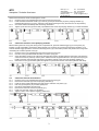
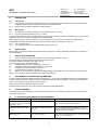
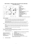
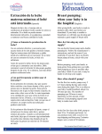
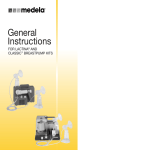
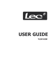
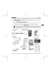
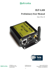
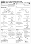
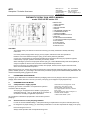
NTS Sp. z o.o.
Sales Office:
ul. Warszawska 749
Borzęcin DuŜy
05-083 Zaborów
NTS
Narzędzia i Technika Serwisowa
tel.: +22 7520600
fax: +22 7520592
www.nts.com.pl
e-mail: [email protected]
PNEUMATIC SPRAY GUN USER’S MANUAL
model CSG-245 RP series 010
PARTS LIST:
1. SPRAY GUN BODY
2. FRONT NUT
3. RELEASE TRIGGER
4. HANDLE
5. AIR PRESSURE CONTROLLER
6. COMPRESSED AIR INLET
7. PUMPING CHAMBER
8. RELEASE-DIFFERENTIAL VALVE
9. REAR NUT
10. ROD FOR PISTON WITHDRAWAL
11. CARTOUCHE CONNECTOR (REDUCER)
12. 400ml SACHET
13. SACHET NOZZLE
14. 310ml CARTOUCHE
15. SPECIAL TOOLS
CAUTION
This symbol draws your attention to the issues involving your safety. Read them carefully and strictly
follow them.
Cut off the pressure supply before carrying out any repairs, maintenance and other operations.
Read the user’s manual before using the spray gun and strictly follow its guidelines.
Contact your nearest dealer or authorised specialist personnel before performing any operations (repairs,
maintenance). Improper operation will render your warranty invalid.
When selecting the product to be pumped with the spray gun, read its Material Safety Data Sheet (MSDS) to
verify its compliance with the work environment and individual safety measures.
Never turn the spray gun outlet towards yourself, other people, animals, and/or objects other than those,
which are to be treated with the product.
While using the spray gun, always wear protective clothing and other protective equipment (safety gloves, goggles, face
guards, overalls, aprons, etc.), according to the instructions provided in sprayed product Material Safety Data Sheet. We
recommend wearing safety goggles at all times.
3.
PACKAGING AND STORAGE
The spray gun is delivered in an individual cardboard packaging sized: 370 mm (length) x 280 mm (width) x 80 mm
(height), white 8t/8343, thickness 2.8-3 mm (low wave). The spray gun is shipped in a polyethylene wrap.
4.
PREPARATION FOR WORK
4.1
Compressed air supply system
The spray gun must be connected to a compressed air system in
accordance with the diagram.
The spray gun is equipped with a “NIPPLE”-type pipe joint
(external thread) (fig. 1 par. 6), which allows the connection of
accessories according to applicable requirements.
Ciśnienie robocze = Working pressure 5-8 bar
Ciśnienie max. = Max. pressure 10 bar
Reduktor z filtrem = Reducer with a filter
Min. przepływ powietrza = Min air flow 200 l/min
Zawór = Valve
Max. długość przewodu = Max. hose length 10 m
Minimalna średnica wewnętrzna
= Minimum inside diameter φ 6 mm
Air consumption is limited and proportional to the number of product
pumpings.
4.2
Sachet insertion in the pumping chamber
In order to avoid accidentall leakage of the product during its replacement in the piston chamber (which may
be dangerous for people nearby), you must always remember to cut off the compressed air supply to the spray
gun
before undoing the front nut.
Always check expiration date of all products being used.
1
NTS Sp. z o.o.
Sales Office:
ul. Warszawska 749
Borzęcin DuŜy
05-083 Zaborów
NTS
Narzędzia i Technika Serwisowa
tel.: +22 7520600
fax: +22 7520592
www.nts.com.pl
e-mail: [email protected]
Never insert cartouches, which are damaged or not full.
4.2.1
Undo the front nut (2) anticlockwise and remove it from the spray gun.
4.2.2
Insert and block the sachet nozzle (13) in the nut (2) and put the sachet (12) in the pumping chamber (7)
(withdraw the piston if it is in front, and push in the sachet ensuring that only the end to be cut off protrudes).
4.2.3
Cut off the sachet immediately after the closing metal band.
4.2.4
Tighten up the front nut (2) with nozzle (13) installed at the end of the pumping chamber (7). Proceed clockwise.
4.3
Cartouche insertion in the pumping chamber
Before undoing the front nut (2) and cutting off the compressed air, press the release trigger (3) to move piston (15)
forward, to make it possible to unscrew the sachet pusher cone if piston (15) comes loose during the operation 4.3.2.
Hold the release trigger pressed to ensure that air keeps piston (15) in its forward position and prevents its turning while
unscrewing the container pusher cone (16).
4.3.1
4.3.2
4.3.3
4.3.4
Undo the front nut (2) anticlockwise and remove it from the spray gun.
Unscrew cone (16) anticlockwise and take it out of the spray gun.
Screw the plastic nozzle on the cartouche clockwise (the nozzle is provided with the cartouche), then place the
cartouche connector (reducer) onto the piston. Make sure that the gasket adheres to front part of the spray gun.
Finally, insert the cartouche and push piston (15) with the reducer to the end of the pumping chamber (7).
Place the front nut (2) with white gasket and tighten it up clockwise until the cartouche is pressed down firmly.
4.4
Cartouche removal and insertion
4.4.1
4.4.2
4.4.3
4.4.4
4.4.5
4.4.6
4.4.7
4.4.8
Undo the front nut (2) anticlockwise and remove it from the spray gun.
Remove the cartouche (14) from the pumping chamber (7).
Insert the rod for piston withdrawal (10) and screw it clockwise onto piston (15).
Pull rod (10) and piston (15) to stroke (travel) end.
Unscrew it anticlockwise and remove it.
Remove the cartouche connector (reducer) (11).
Insert cone (16) and screw it on clockwise.
Tighten it with a 13mm spanner applying a little force.
2
NTS Sp. z o.o.
Sales Office:
ul. Warszawska 749
Borzęcin DuŜy
05-083 Zaborów
NTS
Narzędzia i Technika Serwisowa
tel.: +22 7520600
fax: +22 7520592
www.nts.com.pl
e-mail: [email protected]
5.
DESCRIPTION
5.1
Correct use
5.1.1
5.1.2
The pumping of chemical bonding products (silicone-polyurethane-cement-adhesives-etc.) provided in special
containers, 310ml aluminium or plastic cartouches, and 400ml sachets.
Always work in conditions suitable for certain products.
5.2
Wrong use
5.2.1
5.2.2
The pumping of any other products than those listed in item 5.1.1 above.
Any other use than specified in item 5.1.1 above.
Use the product MSDS to verify if it really matches your equipment, operating conditions, and that the personal protective
equipment used by the operator is suitable for the treated material.
Wile using the spray gun, hold it a minimum of 30 cm away from your face when you release the trigger because
compressed air escaping from the discharge valve may seriously harm your face (eyes, ears, etc.).
5.2.3
5.2.4
Use of loose products.
Use of the spray gun without complete sealing of the front nut (2).
6.
NOISE LEVEL
When trigger (3) is released, the acoustic pressure level corresponds to scale a, measured horizontally at a distance of
50 cm while gluing.
7.
SPRAY GUN OPERATION
7.1
Air flow and product pumping is possible when the following conditions are met:
The main pressure reducing valve and supply valve are open (fig. 2).
The air gun pressure regulator is open (fig. 1, par. 5).
The release trigger (3) is operated manually.
7.2
Sachet loading (into pumping chamber) - see par. 4.2.
7.3
Cartouche loading (into pumping chamber) - see par. 4.3.
7.4
Packaging removal and loading - see par. 4.4.
7.5
Compressed air connection - see par. 4.1.
7.6
Always cut off the pressure supply after finishing working with the spray gun. If the cartouche or sachet are not
empty yet, close them tightly to ensure that they may be reused later.
8.
ADJUSTMENT OF OPERATING PARAMETERS
In order to adjust the pressure with the pressure regulator (fig. 1, par. 5), pull out theplastic knob and turn it anticlockwise
to obtain a gradual increase of pressure and force, with which the product is being pumped. As soon as the parameters
are set, we recommend to push the knob back to block it.
Never exceed maximum allowable pressure (10 bar).
Read the product instructions for use and check the minimum working temperature.
9.
IGNITION HAZARD
A fire hazard may occur depending on the type of product being used. It is prohibited to smoke and use open fire during
work with the spray gun.
10.
IF YOU HAVE PROBLEMS WITH THE EQUIPMENT
PROBLEMS
REASONS
WHAT TO DO
The product does not come out of
the spray gun when you release the
trigger (fig. 3, par. 1).
No compressed air supply.
Check the supply hoses. Open the pressure regulator (see
par. 8 - adjustment of pressure parameters).
Poor and irregular product outflow.
The product is too thick, or pressure
is too low.
Adjust the pressure using the regulator (fig. 1, par. 5).
Increase the pressure if needed. Check if the product and
working temperature are suitable.
The pumping chamber is soiled
after finishing work.
The container has been opened
incorrectly or damaged.
Carefully clean all elements and replace the container. Cut
off the sachet end immediately after the closing metal tape
(see par. 4.2 - sachet insertion).
3
NTS Sp. z o.o.
Sales Office:
ul. Warszawska 749
Borzęcin DuŜy
05-083 Zaborów
NTS
Narzędzia i Technika Serwisowa
tel.: +22 7520600
fax: +22 7520592
www.nts.com.pl
e-mail: [email protected]
11.
CLEANING AND MAINTENANCE
11.1
11.2
11.3
Never expose the spray gun to contact with solvents or acids.
Use only special detergents for spray gun cleaning.
If the spray gun is used according to our guidelines, it will not require any special maintenance.
12.
WARRANTY
We guarantee the quality of our product. If any element is defected due to the manufacturing process, we will replace it
free of charge provided that it is has not been soiled and/or tampered with. All pieces of the set must be delivered to our
company. The manufacturer shall not be held responsible for any damage or harm if the product is used for purposes
other than those intended and contrary to the instructions for use. Spray guns purchased in parts (that is: unassembled,
modified, or incomplete) usually do not have a warranty, since they haven’t been put to final tests (unless these tests
have been specially ordered by the buyer).
4