1
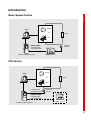
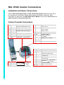
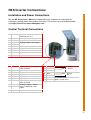
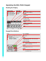
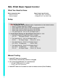
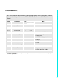
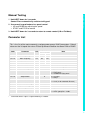
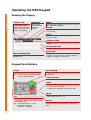
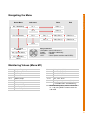
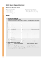
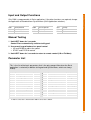
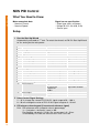
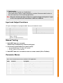
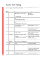
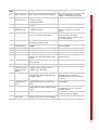
NX Series Inverters
HVAC Pocket Programming Guide
HVAC Pocket Programming Guide / Contents
HVAC Pocket Programming Guide
02
This guide provides a single reference document for the user of NXL HVAC (product codes
starting with HVAC) and NXS (product codes starting with NXS) inverters, when using
Basic Speed Control and PID Control in HVAC applications.
Contents
Introduction
03
NXL HVAC Inverter Connections
Information on control connections of NXL HVAC inverters
04
NXS Inverter Connections
Information on control connections of NXS inverters
05
Operating the NXL HVAC Keypad
Information and tips on operating the keypad
06
NXL HVAC Basic Speed Control
Commissioning and operation in Basic Speed Control
08
NXL HVAC PID Control
Commissioning and operation in PID Control
10
Operating the NXS Keypad
Information and tips on operating the keypad
12
NXS Basic Speed Control
Commissioning and operation in Basic Speed Control
14
NXS PID Control
Commissioning and operation in PID Control
16
Inverter Fault Tracing
Fault codes, possible causes and correcting measures for both product series
18
Introduction
Introduction
Basic Speed Control
Pump
Motor
or
Load
Fan
Pressure
Sensor
Speed Signal
V signal to AI1
mA signal to AI2
Variable Frequency Drive
Control System
PID Control
Pump
Motor
or
Load
Fan
V signal to AI1
mA signal to AI2
Pressure
Sensor
Setpoint Signal
V signal to AI1
mA signal to AI2
Variable Frequency Drive
Control System
03
NXL HVAC Inverter Connections
NXL HVAC Inverter Connections
Installation and Power Connections
See the NXL HVAC Quick Guide and NXL HVAC Safety Guide (attached to each drive)
for information on installation, cabling, cooling, power connections and safety. More
information can be found in the NXL HVAC User’s Manual, which can be downloaded from
http://inverter.ecc.emea.honeywell.com
Control Terminal Connections
1
+ 10 Vref
2
3
4
5
6
7
8
AI1 +
AI1 –
AI2 +
AI2 –
+24 V
GND
DIN1
Reference output
(voltage for potentiometer etc.)
Analogue Input 1 (V signal)
I/O Ground
Analogue Input 2 (mA signal)
+24 V output (max. 0.1 A)
I/O ground
Digital Input 1 (Start forward)
9
DIN2
10 DIN3
Digital Input 3
(Preset speed 1,
default: 10 Hz)
11 GND
I/O Ground
18 AO1 +
Analogue output 1
Range 0–20 mA/RL,
max. 500 Ω
19 AO1 –
A
RS485
B
RS485
30 +24V
21
22
23
04
RO1
RO1
RO1
Relay 1
NO/NC
(fault)
Digital Input 2
(Start reverse)
12
13
14
+ 24 V
GND
DIE1
15
DIE2
16
DIE3
25
26
28
ROE1
ROE1
TI+
29
TI –
Modbus RTU, serial bus
Input for +24 V backup voltage
+24 V output (max. 150 mA)
I/O ground
Exp. Digital Input 1 (Preset
speed 2, default: 50 Hz)
Exp. Digital Input 2
(Fault Reset)
Exp. Digital Input 3
(Disable PID)
Exp. Relay 1
NO (run)
Thermistor Input;
Rtrip = 4.7 k1Ω (PTC)
NXS Inverter Connections
See the NX Series User’s Manual (included with every shipment) for information on
installation, cooling, power connections and safety. The manual can also be downloaded
from http://inverter.ecc.emea.honeywell.com
Control Terminal Connections
1
+10 Vref
2
3
4
5
6
7
8
9
10
AI1 +
AI1 –
AI2 +
AI2 –
+24 V
GND
DIN1
DIN2
DIN3
11
CMA
12
13
14
15
16
17
+24 V
GND
DIN4
DIN5
DIN6
CMB
18
19
AO1 +
AO1 –
20
DO1
NXS Inverter Connections
Installation and Power Connections
Reference output (voltage for
potentiometer etc.)
Analogue Input 1 (V signal)
I/O ground
Analogue Input 2 (mA signal)
+24 V input/output (max. 0.1 A)
I/O ground
Digital Input 1
Digital Input 2
Digital Input 3
Digital input common for DIN1,
DIN2 and DIN3
Same as terminal 6
I/O ground
Digital Input 4
Digital Input 5
Digital Input 6
Digital input common for DIN4,
DIN5 and DIN6
Analogue output 1, default
range: 0–20 mA/RL, max.
500 Ω
Open collector Output
21
22
23
25
26
RO1
RO1
RO1
RO2
RO2
28
29
TI+
TI-
Relay 1
NO/NC
Relay 2
NO
Thermistor Input;
Rtrip = 4.7 kΩ (PTC)
05
Operating the NXL HVAC Keypad
Operating the NXL HVAC Keypad
Reading the Display
RUN and STOP
Indicate if the drive is
running. When RUN
blinks, STOP command
has been given but the
motor is still rotating.
DIRECTION
Active motor
direction visible:
forward or
reverse.
READY
Lights up when AC power is on. In case of a fault,
the symbol will not light up.
ALARM
Lights up to warn that the drive is running outside
a certain limit.
FAULT
Indicates that unsafe operating conditions caused
the drive to stop.
CONTROL PLACE
Active control place is visible: keypad, I/O or
fieldbus.
NUMERIC INDICATIONS
Provide information on values and location in the
menu structure.
UNIT
Unit of the value on screen visible.
Keypad Push-Buttons
LEFT
- In menu: move backward
- In parameter edit mode: move cursor left
- Exit edit mode
Tip: Hold LEFT down 3 – 5 s for
control place change
KEYPAD
REMOTE
UP+ and DOWN–
- Browse the pages in main and submenus
- Edit values
RIGHT
- In menu: move forward
- In parameter edit mode: move cursor right
- Enter edit mode
START and STOP
Control the motor if the keypad is the active control
Tip: Hold STOP down 5 s to launch the
START UP WIZARD
ENTER
- Confirmation of selections
- Fault history reset (2 – 3 s)
RESET
Reset active faults
Note: The motor may start immediately after
resetting the fault!
06
Home Menu
Sub Menu
Value
M1 – Monitoring
V1.1
Value 1
V1.2
Value 2
P2 – Parameters
P2.1
Edit
P2.1.1
Value P2.1.1
Edit P2.1.1
P2.1.2
Value P2.1.2
Edit P2.1.2
Operating the NXL HVAC Keypad
Navigating the Menu
P2.2
K3 – Keypad
S6 – System Menu
E7 – Expander Menu
Edit parameters
UP/DOWN Increase/Decrease
RIGHT
Edit digits individually
ENTER
Confirm
LEFT
Cancel (before confirm with ENTER)
Monitoring Values (Menu M1)
V1.1
V1.2
V1.3
V1.4
V1.5
V1.6
V1.7
V1.8
V1.9
V1.10
V1.11
V1.12
V1.13
V1.14
V1.15*
Output Frequency
Frequency Reference
Motor Speed
Motor Current
Motor Torque
Motor Power
Motor Voltage
DC-link Voltage
Unit Temperature
Analogue Input 1
Analogue Input 2
Analogue Output Current
Extra Analogue Output 1
Extra Analogue Output 2
DIN1, DIN2, DIN3
V1.16**
V1.17*
V1.18**
V1.19
V1.20
V1.21
V1.22
V1.23
V1.24
V1.25
*
**
DIE1, DIE2, DIE3
Relay Output 1
Extra Relays ROE 1, 2, 3
Digital Output 1
PID Reference
PID Actual Value
PID Error Value
PID Output
PFC Autochange 1, 2, 3
Mode
(0 = Not Selected,
1 = Standard,
2 = Fan,
3 = Pump,
4 = High Performance)
Standard I/O
Expander Board I/O (ROE2 and ROE3 not
included in standard delivery)
07
NXL HVAC Basic Speed Control
NXL HVAC Basic Speed Control
What You Need to Know
Motor nameplate data
− Nominal Current
− Nominal Speed
Speed signal specification
− Signal type (volts, milliamps)
− Range (0-10, 2-10, 0-20, 4-20)
Setup
1 Run the Start Up Wizard
Note: Running the Start Up Wizard resets all parameters to their default values.
• Hold STOP button down for 5 seconds
• Select application type FAN or PUMP and confirm with ENTER
• Select motor nominal speed and confirm with ENTER
• Select motor nominal current and confirm with ENTER
• For speed signal 0 – 10 V use AI1 (Analogue Input 1)
2 Control Signal Settings for Speed Signals other than 0 – 10 V
• For other selections full parameter view is needed:
P2.1.14
Parameter Conceal Set to 0 (not in use)
• For speed signal 2 – 10 V use Analogue Input 1
P2.2.6
AI1 Signal Range
Set to 4 (2 – 10 V)
• For speed signal 4 – 20 mA use Analogue Input 2
P2.1.15.14 I/O Reference
Set to 1 (AI2)
• For speed signal 0 – 20 mA use Analogue Input 2
P2.1.15.14 I/O Reference
Set to 1 (AI2)
P2.2.12
AI2 Signal Range
Set to 1 (0 – 20 mA)
Manual Testing
1 Hold LEFT down for 3 seconds
Control Place automatically switches to Keypad
2 Use normal keypad buttons for speed control
• UP and DOWN to adjust the speed
• START and STOP for control
3 Hold LEFT down for 3 seconds to return to remote control (I/O or Fieldbus)
08
This is the list of the most commonly used parameter group: HVAC parameters. Default
values on the list equal the values if FAN or PUMP has been selected in Start Up
Wizard.
*
Code
Parameter
Unit
P2.1.1
P2.1.2
P2.1.3
P2.1.4
P2.1.5
P2.1.6
P2.1.7
P2.1.8
Min. frequency
Max. frequency
Accel. time 1
Decel. time 1
Current limit
Motor nominal current
Motor nominal speed
Start function
Hz
Hz
S
S
A
A
Rpm
P2.1.9
Stop function
P2.1.10
Automatic restart
P2.1.11
P2.1.12
P2.1.13
P2.1.14
Motor nominal voltage
Motor nominal frequency
Preset speed 1
Parameter conceal
V
Hz
Hz
Default
Note
FAN PUMP
20
20
50
50
20.0
5.0
20.0
5.0
1.1 x lL
IL
Value set in Start Up Wizard
1440
Value set in Start Up Wizard
2
0 = Ramp
1 = Flying Start
2 = Conditional Flying Start*
0
0 = Coasting
1 = Ramp
0
0 = Not used
1 = Used
400
50.00
10.00
1
0 = All parameters and menus visible
1 = HVAC group P2.1 visible
NXL HVAC Basic Speed Control
Parameter List
Start mode where Tripless Output Switching is enabled, recommended to be used with all pump
and fan applications
09
NXL HVAC PID Control
NXL HVAC PID Control
What You Need to Know
Motor nameplate data
− Nominal Current
− Nominal Speed
Signal/sensor specification
− Signal type
(volts, milliamps)
− Range
(0-10, 2-10, 0-20, 4-20)
− Sensor span
Setup
3 Run the Start Up Wizard
Note: Running the Start Up Wizard resets all parameters to their default values.
• Hold STOP down for 5 seconds
• Select application type FAN or PUMP and confirm with ENTER
• Select motor nominal speed and confirm with ENTER
• Select motor nominal current and confirm with ENTER
4 Full view of parameters
• P2.1.14
Parameter Conceal
Set to 0 (not in use)
5 Control Signal Settings
• For Volt sensor signal use Analogue Input 1 (AI1)
0 – 10 V
Default
(no settings needed)
2 – 10 V
P2.2.6 AI1 signal range
Set to 4
• For milliamp sensor signal use Analogue Input 2 (AI2)
4 – 20 mA Default
(no settings needed)
0 – 20 mA P2.2.12 AI2 signal range
Set to 1
6 PID
• PID settings
P2.9.1
PID activation
Set to 1 (activate)
P2.9.2
PID reference
no external reference
Set to 2 (value from keypad)
external reference
Set to 0 (AI1) or 1 (AI2)
• Where is the sensor connected?
P2.9.3
Actual value input
Set to 0 (AI1) or 1 (AI2)
• PID reference (set-point)
Note: Only apply if not using external reference from controller!
P3.5
PID reference value (Set point value in percentage)
% = ((set-point – minimum) / span) x 100
For example: set-point is 3.2 bar, the sensor span is 0 – 5 bar.
3.2 divided by 5 is 0.64; the value to set in P3.5 is thus 64
Note: Only one function per input. If there is a need to change mA input to V input or
vice versa, please see instructions in the NXL HVAC User’s Manual. Available for
download at http://inverter.ecc.emea.honeywell.com
10
1 Hold LEFT down for 3 seconds
Control Place automatically switches to Keypad
2 Use normal keypad buttons for speed control
• UP and DOWN for adjusting the speed
• START and STOP for control
NXL HVAC PID Control
Manual Testing
3 Hold LEFT down for 3 seconds to return to remote control (I/O or Fieldbus)
Parameter List
This is the list of the most commonly used parameter group: HVAC parameters. Default
values on the list equal the values if Start Up Wizard selection has been FAN or PUMP.
*
Code
Parameter
Unit
P2.1.1
P2.1.2
P2.1.3
P2.1.4
P2.1.5
P2.1.6
P2.1.7
P2.1.8
Min. frequency
Max. frequency
Accel. time 1
Decel. time 1
Current limit
Motor nominal current
Motor nominal speed
Start function
Hz
Hz
S
S
A
A
Rpm
P2.1.9
Stop function
P2.1.10
Automatic restart
P2.1.11
P2.1.12
P2.1.13
P2.1.14
Motor nominal voltage
Motor nominal frequency
Preset speed 1
Parameter conceal
V
Hz
Hz
Default
Note
FAN PUMP
20
20
50
50
20.0
5.0
20.0
5.0
1, 1xlL
IL
Value set in Start Up Wizard
1440
Value set in Start Up Wizard
2
0 = Ramp
1 = Flying Start
2 = Conditional Flying Start*
0
0 = Coasting
1 = Ramp
0
0 = Not used
1 = Used (3x for automatic Restart)
400
50.00
10.00
1
0 = All parameters and menus visible
1 = HVAC group P2.1 visible
Start mode where Tripless Output Switching is enabled.
11
Operating the NXS Keypad
Operating the NXS Keypad
Reading the Display
RUN and STOP
Indicate if the drive is
running. When RUN
blinks, STOP command
has been given but the
motor is still rotating.
DIRECTION
Active motor
direction visible:
forward or
reverse.
READY
Lights up when AC power is on. In case of a fault,
the symbol will not light up.
ALARM
Lights up to warn that the drive is running outside
a certain limit.
FAULT
Indicates that unsafe operating conditions caused
the drive to stop.
CONTROL PLACE
Active control place is visible: keypad, I/O or
fieldbus.
DESCRIPTION LINE
Displays the description of menu, value or fault.
LOCATION INDICATION
Displays the symbol and number of menu,
parameter etc.
VALUE LINE
Displays the numerical and textual values of
references, parameters etc. and the number of
submenus available in each menu.
Keypad Push-Buttons
LEFT
RESET
- In Menu: move backward
Reset
active faults
- In parameter
edit mode: move cursor left
Note:
Themode
motor may start immediately
- Exit edit
after LEFT
resetting
the3s
fault!
Tip: Hold
down
for
control place change LOCAL
<-> Remote
LEFT
- In menu: move forward
- In parameter edit mode: move cursor left
- In edit mode: exit
Tip: Hold LEFT down 3 – 5 s for
control place change
KEYPAD
REMOTE
12
UP+ and DOWNand the
DOWN–
-UP+
Browse
pages in main and submenus
Browse
the pages in main and submenus
- Edit values
- Edit values
RIGHT
AND
STOP
-START
In Menu:
move
forward
-Control
In parameter
editifmode:
move is
cursor
right control
the motor
the keypad
the active
- Enter edit mode
RIGHT
- In menu: move forward
- In menu: enter edit mode
- In parameter edit mode: move cursor right
ENTER
- Confirmation of selections
- Fault history reset (2 – 3 s)
SELECT
Switch between the last two displays. To see how
the changed new value influences some other
value.
Home Menu
Sub menu
Value
M1 – Monitoring
V1.1
Value 1
V1.2
Value 2
P2 – Parameters
P2.1
Edit
P2.1.1
Value P2.1.1
Edit P2.1.1
P2.1.2
Value P2.1.2
Edit P2.1.2
Operating the NXS Keypad
Navigating the Menu
P2.2
K3 – Keypad
control
S6 – System Menu
E7 – Expander
Menu
Edit parameters
UP/DOWN Increase/Decrease
RIGHT
Edit digits individually
ENTER
Confirm
LEFT
Cancel (before confirm with ENTER)
Monitoring Values (Menu M1)
V1.1
V1.2
V1.3
V1.4
V1.5
V1.6
V1.7
V1.8
V1.9
V1.10
Output Frequency
Frequency Reference
Motor Speed
Motor Current
Motor Torque
Motor Power
Motor Voltage
DC-link Voltage
Unit Temperature
Motor Temperature
V1.11
V1.12
V1.13
V1.14
V1.15
V1.16
V1.17*
*
Voltage Input (AI1)
Current Input (AI2)
DIN1, DIN2, DIN3
DIN4, DIN5, DIN6
DO1, RO1, RO2
Analogue output current (AO1)
Multimonitoring items (displays
3 selectable items simultaneously)
Multimonitoring values can be selected in
V1.17 by using RIGHT arrow to enter the
edit mode
13
NXS Basic Speed Control
NXS Basic Speed Control
What You Need to Know
Motor nameplate data
− Nominal Current
− Nominal Speed
− Nominal Voltage, etc.
Speed signal specification
− Signal type (volts, milliamps)
− Range (0-10, 2-10, 0-20, 4-20)
Setup
1 Run the Start Up Wizard
Automatically activated at 1st start.
To restart the wizard, set P6.5.3 Start Up Wizard to Yes and cycle the main power.
Step Question
Basic Settings
1
Language
2
Application
Application Settings
3
Min. Frequency
4
Max. Frequency
5
Acceleration Time
6
Deceleration Time
Motor Settings
7
Nom. Voltage for the motor
8
Nom. Frequency for the motor
9
Nom. Speed for the motor
10
Nom. Current for the motor
11
Motor Cos ϕ
Speed Signal Settings
12
I/O Reference
Recommendation
Note
English
Basic
20 Hz
Typical for Fan or Pump
50 Hz
Typical for Fan or Pump
30 s for Fan, 15 s for Pump
30 s for Fan, 15 s for Pump
Check motor nameplate
Check motor nameplate
Check motor nameplate
Check motor nameplate
Check motor nameplate
Default typically OK
Default typically OK
Critical
Critical
Default typically OK
mA signal: AI2
V signal: AI1
Default signal: 4 – 20 V
Default signal: 0 – 10 V
2 Other Control Signal Settings
P2.15
Current reference offset
Set to “No offset, 0 – 20 mA”
3 Start function
P2.11
Start Function
Set to “CondFlyStart”
Start mode where Tripless Output Switching is enabled. Recommended function to
be used especially in fan and pump applications.
14
Only DIN3 is programmable in Basic application. If the other functions are required, change
the application to Standard from System Menu (S6.2 Application selection).
DIN1
DIN2
DIN3
Start Forward
Start Reverse
External Fault
DIN4
DIN5
DIN6
Preset Speed 1
Preset Speed 2
Fault reset
DO1
RO1
RO2
Ready
Run
Fault
NXS Basic Speed Control
Input and Output Functions
Manual Testing
1 Hold LEFT down for 3 seconds
Control Place automatically switches to Keypad
2 Use normal keypad buttons for speed control
• UP and DOWN to adjust the speed
• START and STOP for control
3 Hold LEFT down for 3 seconds to return to remote control (I/O or Fieldbus)
Parameter List
This is the list of the basic parameters that is the only group visible when the Basic
application is selected (in addition to Keypad and System Menu, which are always
visible).
Code
P2.1
P2.2
P2.3
P2.4
P2.5
P2.6
P2.7
P2.8
P2.9
P2.10
*
Parameter
Min. frequency
Max. frequency
Acceleration time
Deceleration time
Current limit
Motor nominal voltage
Motor nominal frequency
Motor nominal speed
Motor nominal current
Motor Cos ϕ
Default
0 Hz
50 Hz
3.0 s
3.0 s
IL
400 V*
50 Hz
1440
IH
0.85
Code
P2.11
P2.12
P2.13
P2.14
P2.15
P2.16
P2.17
P2.18
P2.19
P2.20
Parameter
Start function
Stop function
U/f optimization
I/O reference
Current reference offset
Analogue output function
DIN3 function
Preset speed 1
Preset speed 2
Automatic restart
Default
Ramp
Coasting
Not used
AI1
Offset 4-20 mA
Output Freq.
External Fault
0 Hz
50 Hz
Disabled
In 230 V series this is 230 V and in 690 V series this is 690 V.
15
NXS PID Control
NXS PID Control
What You Need to Know
Motor nameplate data
− Nominal Current
− Nominal Speed
Signal/sensor specification
− Signal type (volts, milliamps)
− Range (0-10, 2-10, 0-20, 4-20)
− Sensor span
Setup
1 Run the Start Up Wizard
Automatically activated at 1st start. To restart the wizard, set P6.5.3 Start Up Wizard
to Yes and cycle the main power.
Step Question
Basic Settings
1
Language
2
Application
Application Settings
3
Min. Frequency
4
Max. Frequency
5
Acceleration Time
6
Deceleration Time
Motor Settings
7
Nom. Voltage for the motor
8
Nom. Frequency for the motor
9
Nom. Speed for the motor
10
Nom. Current for the motor
11
Motor Cos ϕ
PID and Sensor Settings
12
PID Reference
13
Actual Input
Recommendation
Note
English
PID Control
20 Hz
Typical for Fan or Pump
50 Hz
Typical for Fan or Pump
30 s for Fan, 15 s for Pump
30 s for Fan, 15 s for Pump
Check motor nameplate
Check motor nameplate
Check motor nameplate
Check motor nameplate
Check motor nameplate
Default typically OK
Default typically OK
Critical
Critical
Default typically OK
Keypad reference
mA signal: AI2
V Signal: AI1
Fieldbus
mA signal: AI2
V signal: AI1
No controller
Signal from controller
Default: 4 – 20 mA
Default: 0 – 10 V
2 Other Control Signal Settings
2 – 10 V: change the value of P2.2.16 AI1 signal range to 20 – 100 %
0 – 20 mA: change the value of P2.2.22 AI2 signal range to 0 – 20 mA
3 PID reference from keypad (if no external reference signal)
R3.4 PID reference value (set-point value in percentage)
% = ((set-point – minimum) / span) x 100
For example: set-point is 3.2 bar, the sensor span is 0 – 5 bar.
3.2 divided by 5 is 0.64; the value to set in P3.5 is thus 64
16
Note: Only one function per input. If there is a need to change mA input to V input
or vice versa, please see instructions in NX User’s Manual.
NXS PID Control
4 Start function
Set P2.4.6 Start Function to “CondFlyStart”
Start mode where Tripless Output Switching is enabled. Recommended function to
be used especially in fan and pump applications.
Input and Output Functions
All inputs and outputs are programmable. Here are the default values:
DIN1
DIN2
DIN3
DIN4
DIN5
DIN6
Start A (PID controller)
External Fault
Fault Reset
Start B (direct frequency reference)
Jogging Speed
Control place A/B selection:
open = A (PID)
closed = B (direct reference)
DO1
RO1
RO2
AO1
Ready
Run
Fault
Output frequency
Manual Testing
1 Hold LEFT down for 3 seconds
Control Place automatically switches to Keypad
2 Use normal keypad buttons for speed control
• Up and down arrows to adjust the speed
• START and STOP for control
3 Hold LEFT down for 3 seconds to return to remote control (I/O or Fieldbus)
Parameter Menus
Here is the list of parameter menus available in PID application.
Code
2.1
2.2
2.3
2.4
2.5
2.6
2.7
2.8
Parameter
Basic parameters
Input signals
Output signals
Drive control
Prohibit frequency
Motor control
Protections
Auto restart
Description
All basic settings for operation and PID
Settings for input signals
Settings for output signals
Specific settings for VFD (Start/Stop functions etc.)
Settings for resonance elimination
Specific settings for motor control
Settings for VFD protections
Settings for automatic restart functions
17
Inverter Fault Tracing
Inverter Fault Tracing
Conveniently, the fault coding and trip logic are similar in all Honeywell NX inverters. This
table thus applies to both NXS and NXL HVAC.
Fault
Code
Fault
Possible Cause
Correcting measures
1
Overcurrent
Frequency converter has detected too
high a current (> 4 * In) in the motor
cable:
- Sudden heavy load increase.
- Short circuit in motor cables.
- Unsuitable motor.
Check loading.
Check cables.
Check motor size.
2
Overvoltage
The DC-link voltage has exceeded the
limits
- Too short a deceleration time.
- High overvoltage spikes in utility.
Increase deceleration time.
3
Earth fault
Current measurement has detected that
the sum of motor phase current is not
zero:
- Insulation failure in cables or motor.
Check motor cables and motor.
5
Charging switch
The charging switch is open when the
Start command has been given.
- Faulty operation.
- Component failure.
Reset the fault and restart.
Should the fault recur, contact the
technical support.
7
Saturation trip
Various causes, e.g. faulty component.
8
System fault
- Component failure.
- Faulty operation.
Cannot be reset from the keypad.
Switch off power. Do not connect
power. Contact Honeywell.
If this fault appears simultaneously with
Fault 1, check motor cables and motor.
Reset the fault and restart.
Should the fault recur, contact the
technical support.
9
Undervoltage
DC-link voltage is under the voltage
limits:
- Most probable cause: too low a supply
voltage.
- Frequency converter internal fault.
In case of temporary supply voltage
break, reset the fault and restart the
frequency converter. Check the supply
voltage. If it is adequate, an internal
failure has occurred.
Contact the technical support.
10
Input line
supervision
Input line phase is missing.
Check supply voltage and cable.
11
Output Phase
Supervision
Current measurement has detected that
there is no current in one motor phase.
Check motor cables and motor.
13
Inverter under
temp.
Inverter over
temp.
Heatsink temperature is under
– 10 °C.
Heatsink temperature is over 90 °C.
Overtemperature warning is issued when
the heatsink temperature exceeds 85 °C.
Check that the inverter is operated
under specified conditions.
Check the correct amount and flow of
cooling air.
Check the heatsink for dust.
Check the ambient temperature.
Make sure that the switching frequency
is not too high in relation to ambient
temperature and motor load.
15
Motor stalled
Motor stall protection has tripped.
Check motor.
Check that pump or fan is not blocked.
16
Motor over temp.
Motor overheating has been detected by
frequency converter motor temperature
model. Motor is overloaded.
Decrease the motor load.
If no motor overload exists, check the
temperature model parameters.
14
18
Fault
Possible Cause
Correcting measures
17
Motor under load
Motor underload protection has tripped.
FAN: check that belt is not broken.
PUMP: check that pump is not dry.
22
EEPROM
checksum fault
Parameter save fault:
- Faulty operation.
- Component failure.
Contact the technical support.
24
Counter fault
Values displayed on counters are
incorrect.
Contact the technical support.
25
Microprocessor
watchdog fault
- Faulty operation.
- Component failure.
Reset the fault and restart. Should the
fault recur, contact the technical
support.
29
Thermistor fault
The thermistor input has detected
increase of the motor temperature.
32
Fan cooling
34
35
Internal bus
communication
Application fault
Cooling fan of the inverter does not start,
when ON command is given.
Ambient interference of defective
hardware.
Selected application does not function.
Check motor cooling and loading.
Check thermistor connection.
(If thermistor input is not in use, it has
to be short circuited.)
Contact the technical support.
Should the fault recur, contact the
technical support.
Contact the technical support.
39
Device removed
Option board removed. Drive removed.
Reset.
40
Device unknown
Unknown option board or drive.
Contact the technical support.
41
IGBT temperature IGBT Inverter Bridge overtemperature
protection has detected to high a motor
current.
Check loading.
Check motor size.
44
Device change
Option board changed. Option board has
default settings.
Reset.
45
Device added
Option board added.
Reset.
50
Analogue input Iin
< 4 mA (selected
signal range 4 to
20 mA)
External fault
Current at the analogue input is < 4 mA.
- Control cable is broken or loose.
- Signal source has failed.
Check the current loop circuitry.
Digital input fault. Digital input has been
programmed as external fault input and
this input is active.
Check the programming and the device
indicated by the external fault
information. Check also the cabling of
this device.
Check keypad connection and possible
keypad cable.
51
52
Keypad
communication
fault
The connection between the control
keypad and the frequency converter is
broken.
53
Fieldbus fault
The data connection between the
fieldbus Master and the fieldbus board is
broken.
Check installation.
If installation is correct, contact the
technical support.
54
Slot fault
Defective option board or slot.
Check board and slot.
Contact the technical support.
55
Actual value
supervision
Actual value has exceeded or fallen
below the actual value supervision limit.
Check the process.
Inverter Fault Tracing
Fault
Code
19
Find out more
For more information on Honeywell’s
frequency converters and other
Honeywell products, visit us online at
http://ecc.emea.honeywell.com
Automation and Control Solutions
Honeywell GmbH
Böblinger Straße 17
71101 Schönaich
Telephone (49) 7031 637 01
Telefax
(49) 7073 637 493
www.honeywell.com
EN2B-0338GE51 R0410
April 2010
© 2010 Honeywell International Inc.