1
Foreword
SIMATIC HMI WinCC flexible 2005 WinCC flexible 2005 Micro
Introduction to
WinCC flexible Micro
1
______________
SIMATIC HMI
WinCC flexible 2005
Micro
User's Manual
WinCC flexible Engineering
System
2
______________
3
Working with Tags
______________
4
Creating Screens
______________
5
Creating an Alarm System
______________
6
Configuring the connection
______________
7
Using Global Events
______________
Structure of Multilingual
Projects
8
______________
9
Project documentation
______________
10
Transfer
______________
11
Configuration Examples
______________
12
Appendix
______________
Order number 6AV6691-1AA01-0AB0
Edition 06/2005
A5E00280157-02
Safety Guidelines
This manual contains notices you have to observe in order to ensure your personal safety, as well as to prevent
damage to property. The notices referring to your personal safety are highlighted in the manual by a safety alert
symbol, notices referring only to property damage have no safety alert symbol. These notices shown below are
graded according to the degree of danger.
Danger
indicates that death or severe personal injury will result if proper precautions are not taken.
Warning
indicates that death or severe personal injury may result if proper precautions are not taken.
Caution
with a safety alert symbol, indicates that minor personal injury can result if proper precautions are not taken.
Caution
without a safety alert symbol, indicates that property damage can result if proper precautions are not taken.
Notice
indicates that an unintended result or situation can occur if the corresponding information is not taken into
account.
If more than one degree of danger is present, the warning notice representing the highest degree of danger will
be used. A notice warning of injury to persons with a safety alert symbol may also include a warning relating to
property damage.
Qualified Personnel
The device/system may only be set up and used in conjunction with this documentation. Commissioning and
operation of a device/system may only be performed by qualified personnel. Within the context of the safety notes
in this documentation qualified persons are defined as persons who are authorized to commission, ground and
label devices, systems and circuits in accordance with established safety practices and standards.
Prescribed Usage
Note the following:
Warning
This device may only be used for the applications described in the catalog or the technical description and only in
connection with devices or components from other manufacturers which have been approved or recommended
by Siemens. Correct, reliable operation of the product requires proper transport, storage, positioning and
assembly as well as careful operation and maintenance.
Trademarks
All names identified by ® are registered trademarks of the Siemens AG. The remaining trademarks in this
publication may be trademarks whose use by third parties for their own purposes could violate the rights of the
owner.
Disclaimer of Liability
We have reviewed the contents of this publication to ensure consistency with the hardware and software
described. Since variance cannot be precluded entirely, we cannot guarantee full consistency. However, the
information in this publication is reviewed regularly and any necessary corrections are included in subsequent
editions.
Siemens AG
Automation and Drives
Postfach 48 48
90437 NÜRNBERG
GERMANY
Order No.: 6AV6691-1AA01-0AB0
Edition 06/2005
Copyright © Siemens AG 2005.
Technical data subject to change
Foreword
Purpose of this manual
This user manual is part of the WinCC flexible Micro documentation. The manual provides
you with a complete overview of project configuration with WinCC flexible Micro. The manual
supports you in creating new projects, in the procedure used during configuration and in
transferring a project to an HMI device.
The manual is intended for newcomers, operators and project engineers involved in
configuration, commissioning, installation and service with WinCC flexible Micro.
The help integrated in WinCC flexible, the WinCC flexible Information System, contains
detailed information. The information system contains instructions, examples and reference
information in electronic form.
Basic Knowledge Requirements
General knowledge in the field of automation engineering is required to understand this
manual.
You should also have experience of using PCs running under the Windows 2000 or
Windows XP operating systems.
Scope of the Manual
This manual is valid for the WinCC flexible Micro 2005 software package.
Position in the information scheme
This manual is part of the SIMATIC HMI documentation. The information below presents an
overview of the information landscape of SIMATIC HMI.
User manual
The following documents marked with (*) are recommended for understanding the Micro
Edition.
• WinCC flexible Micro (*)
– Describes the engineering basics based on the WinCC flexible Micro engineering
system
• WinCC flexible Compact/ Standard/ Advanced
– describes the engineering basics based on the WinCC flexible Compact,
WinCC flexible Standard and WinCC flexible Advanced engineering systems (ES)
• WinCC flexible Runtime:
– Describes how to commission and operate your Runtime project on a PC.
WinCC flexible 2005 Micro
User's Manual, Edition 06/2005, 6AV6691-1AA01-0AB0
i
Foreword
• WinCC flexible Migration:
– Describes how to convert an existing ProTool project to WinCC flexible.
– Describes how to convert an existing WinCC project to WinCC flexible.
– Describes how to migrate ProTool projects with an HMI migration from OP3 to OP 73 or
OP 73micro.
– Describes how to migrate ProTool projects with an HMI migration from OP7 to OP 77B
or OP 77A.
– Describes how to migrate ProTool projects with an HMI migration from OP17 to
OP 177B.
– Describes how to migrate ProTool projects with HMI migration from RMOS graphic
devices to Windows CE devices.
• Communication:
– Communication Part 1 describes the connection of the HMI device to SIMATIC PLCs.
– Communication Part 2 describes the connection of the HMI device to third-party PLCs.
Operating Instructions
• Operating instructions for SIMATIC HMI devices:
– OP 73, OP 77A, OP 77B
– TP 170micro, TP 170A, TP 170B, OP 170B (*)
– OP 73micro, TP 177micro
– TP 177A, TP 177B, OP 177B
– TP 270, OP 270
– MP 270B
– MP 370
• Operating instructions for mobile SIMATIC HMI devices:
– Mobile Panel 170
• Operating instructions (compact) for SIMATIC HMI devices:
– OP 77B
– Mobile Panel 170
Getting Started
• WinCC flexible for first time users:
– Based on a sample project, this is a step-by-step introduction to the basics of
configuring screens, alarms, and recipes, and screen navigation.
• WinCC flexible for advanced users:
– Based on a sample project, this is a step-by-step introduction to the basics of
configuring logs, project reports, scripts, user management, and multilingual projects,
and integration into STEP 7.
• WinCC flexible options:
– Based on a sample project, this is a step-by-step introduction to the basics of
configuring the WinCC flexible Audit, Sm@rtServices, Sm@rtAccess and OPC Server
options.
ii
WinCC flexible 2005 Micro
User's Manual, Edition 06/2005, 6AV6691-1AA01-0AB0
Foreword
Online availability
The following links provide direct access to technical documentation on SIMATIC products
and systems in English, German, French, Italian, and Spanish.
• SIMATIC Guide Technische Dokumentation in Deutsch:
"http://www.ad.siemens.de/simatic/portal/html_00/techdoku.htm"
• SIMATIC Guide for Technical Documentation in English:
"http://www.ad.siemens.de/simatic/portal/html_76/techdoku.htm"
Guide
Structure of this manual:
• Introduction to WinCC flexible – Chapter 1
• Working with WinCC flexible – Chapters 2 -9
• Transferring a project to an HMI device – Chapter 10
• Configuration Examples – Chapter 11
Conventions
A distinction is made in the naming conventions for the configuration and runtime software:
• "WinCC flexible 2005" refers to the configuration software.
• "Runtime" designates the runtime software running on the HMI devices.
• "WinCC flexible Runtime" designates the visualization product for use on standard PCs or
panel PCs.
The term "WinCC flexible" is used in the general context. A version name such as
"WinCC flexible 2005" is used whenever it is necessary to distinguish it from other versions.
An edition name such as "WinCC flexible Micro" is always used to distinguish it from other
editions.
The following conventions are used in the text and will help you to read the manual more
effectively:
Representational Form
Scope
"Add screen"
•
•
•
Terminology that occurs in the user interface, e.g., dialog
names, tabs, buttons, menu commands.
Inputs required, e.g., limit values, tag values
Path information
"File > Edit"
Operational sequences, e.g., menu commands/shortcut menu
commands.
<F1>, <Alt + P>
Keyboard inputs
Please observe notes labeled as follows:
Note
Notes containing important information about the product and its use or a specific section of
the documentation to which you should pay particular attention.
WinCC flexible 2005 Micro
User's Manual, Edition 06/2005, 6AV6691-1AA01-0AB0
iii
Foreword
Registered trademarks
HMI®
SIMATIC®
SIMATIC HMI®
SIMATIC ProTool®
SIMATIC WinCC®
SIMATIC WinCC flexible®
Third parties using for their own purposes any other names in this document which refer to
trademarks might infringe upon the rights of the trademark owners.
Additional support
Representatives and offices
If you have any unanswered questions about the products in this manual, consult your
Siemens contact at your local agency or branch office.
You can locate your contact partner on this Internet URL:
"http://www.siemens.com/automation/partner"
A guide to our technical documentation for the various SIMATIC products and systems is
available at:
"http://www.siemens.com/simatic-tech-doku-portal"
The online catalog and the online ordering system is available at:
"http://mall.automation.siemens.com"
Training center
To familiarize you with automation systems, we offer a variety of courses. Please contact
your regional training center or the central training center in D-90327 Nuremberg.
Phone:
+49 (911) 895-3200
Internet:
"http://www.sitrain.com"
Technical Support
You can reach the Technical Support for all A&D products
Via the Support Request Web form
"http://www.siemens.com/automation/support-request"
Telephone: + 49 180 5050 222
Fax:
+ 49 180 5050 223
Additional information about our Technical Support can be found on the Internet pages at:
"http://www.siemens.com/automation/service"
iv
WinCC flexible 2005 Micro
User's Manual, Edition 06/2005, 6AV6691-1AA01-0AB0
Foreword
Service & Support on the Internet
In addition to our documentation services, you can also make use of all our online
knowledge base on the Internet.
"http://www.siemens.com/automation/service&support"
There you find:
• The Newsletter, which provides the latest information on your products.
• Relevant documentation for your application, which you can access via the search
function in Service & Support
• A forum where users and experts from all over ther world exchange ideas.
• You local Automation & Drives representative.
• Information about on-site services, repairs, spare parts. And lots more under "Services".
WinCC flexible 2005 Micro
User's Manual, Edition 06/2005, 6AV6691-1AA01-0AB0
v
Foreword
vi
WinCC flexible 2005 Micro
User's Manual, Edition 06/2005, 6AV6691-1AA01-0AB0
Table of contents
Foreword .....................................................................................................................................................i
1
2
3
Introduction to WinCC flexible Micro ....................................................................................................... 1-1
1.1
Components of WinCC flexible .................................................................................................. 1-1
1.2
Configuration Support ................................................................................................................ 1-2
WinCC flexible Engineering System ....................................................................................................... 2-1
2.1
Basic Principles on the Programming Interface......................................................................... 2-1
2.2
2.2.1
2.2.2
2.2.3
2.2.4
2.2.5
2.2.6
WinCC flexible user interface..................................................................................................... 2-2
WinCC flexible User Interface Elements.................................................................................... 2-2
Menus and Toolbars .................................................................................................................. 2-3
Work area................................................................................................................................... 2-4
Project View ............................................................................................................................... 2-5
Property view ............................................................................................................................. 2-6
Output View................................................................................................................................ 2-6
2.3
Working with the Mouse............................................................................................................. 2-7
2.4
Keyboard control........................................................................................................................ 2-8
2.5
2.5.1
2.5.2
2.5.3
2.5.4
2.5.5
2.5.6
Working with WinCC flexible...................................................................................................... 2-9
Displaying Help .......................................................................................................................... 2-9
Editor Properties ...................................................................................................................... 2-10
Opening an Editor .................................................................................................................... 2-11
Editing Multiple Projects with WinCC flexible .......................................................................... 2-12
Object list ................................................................................................................................. 2-13
Function List............................................................................................................................. 2-14
2.6
WinCC flexible Start Center ..................................................................................................... 2-16
Working with Tags .................................................................................................................................. 3-1
3.1
3.1.1
3.1.2
Basics......................................................................................................................................... 3-1
External tags .............................................................................................................................. 3-1
Internal Tags .............................................................................................................................. 3-2
3.2
3.2.1
3.2.2
Elements and basic settings ...................................................................................................... 3-2
"Tag" Editor ................................................................................................................................ 3-2
Basic tag settings....................................................................................................................... 3-4
3.3
3.3.1
3.3.2
3.3.3
3.3.4
Working with Tags ..................................................................................................................... 3-6
Properties of a Tag .................................................................................................................... 3-6
External Tags for Communication with the PLC ........................................................................ 3-7
Tag limit values .......................................................................................................................... 3-8
Updating the Tag Value in Runtime........................................................................................... 3-9
3.4
Array basics ............................................................................................................................. 3-10
3.5
Cycle basics ............................................................................................................................. 3-11
3.6
Importing Tags ......................................................................................................................... 3-12
WinCC flexible 2005 Micro
User's Manual, Edition 06/2005, 6AV6691-1AA01-0AB0
vii
Table of contents
3.6.1
3.6.2
3.6.3
3.6.4
4
5
6
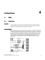
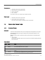
Creating Screens .................................................................................................................................... 4-1
4.1
4.1.1
4.1.2
4.1.3
4.1.4
Basics......................................................................................................................................... 4-1
Screen Basics ............................................................................................................................ 4-1
"Screens" Editor ......................................................................................................................... 4-2
Planning the creation of screens................................................................................................ 4-4
Managing Screens ..................................................................................................................... 4-4
4.2
4.2.1
4.2.2
Objects of the "Screens" editor .................................................................................................. 4-5
Overview of Objects ................................................................................................................... 4-5
Object Groups ............................................................................................................................ 4-7
4.3
The Advantage of Layers ........................................................................................................... 4-7
4.4
Security in Runtime .................................................................................................................... 4-8
Creating an Alarm System ...................................................................................................................... 5-1
5.1
5.1.1
5.1.2
5.1.2.1
5.1.2.2
5.1.2.3
5.1.3
5.1.3.1
5.1.3.2
Basics......................................................................................................................................... 5-1
Visualization of process and system alarms .............................................................................. 5-1
User-defined alarms................................................................................................................... 5-2
Available Alarm Procedures....................................................................................................... 5-2
Acknowledging Alarms............................................................................................................... 5-2
Alarm classes............................................................................................................................. 5-3
Displaying Alarms ...................................................................................................................... 5-4
Displaying Alarms on the HMI Device........................................................................................ 5-4
System Functions for Alarm Editing........................................................................................... 5-5
5.2
5.2.1
5.2.2
5.2.2.1
5.2.2.2
5.2.2.3
5.2.3
Elements and basic settings ...................................................................................................... 5-6
Alarm Components and Properties............................................................................................ 5-6
Editors for Configuring Alarms ................................................................................................... 5-7
Basic Principles of Editors.......................................................................................................... 5-7
"Discrete Alarms" editor ............................................................................................................. 5-8
"Alarm Classes" Editor ............................................................................................................... 5-9
Basic Settings for the Alarm System........................................................................................ 5-10
Configuring the connection ..................................................................................................................... 6-1
6.1
7
8
viii
Importing Tags in WinCC flexible............................................................................................. 3-12
Settings for the Tag Import....................................................................................................... 3-12
Format of the Connection Data for the Import ......................................................................... 3-14
Format of the Tag Data for the Import ..................................................................................... 3-15
"Connections" Editor .................................................................................................................. 6-1
Using Global Events ............................................................................................................................... 7-1
7.1
Use Cases for Global Triggers................................................................................................... 7-1
7.2
Working with Events................................................................................................................... 7-1
7.3
7.3.1
Elements of Global Triggers....................................................................................................... 7-2
Operating range of the Global Triggers ..................................................................................... 7-2
Structure of Multilingual Projects ............................................................................................................ 8-1
8.1
WinCC flexible terminology ........................................................................................................ 8-1
8.2
Multilingual configuration............................................................................................................ 8-3
8.3
8.3.1
8.3.2
Language Settings ..................................................................................................................... 8-4
Language settings in the operating system ............................................................................... 8-4
"Project Languages" editor......................................................................................................... 8-5
8.4
Languages in Runtime ............................................................................................................... 8-6
WinCC flexible 2005 Micro
User's Manual, Edition 06/2005, 6AV6691-1AA01-0AB0
Table of contents
9
10
11
12
Project documentation ............................................................................................................................ 9-1
9.1
Project documentation ............................................................................................................... 9-1
9.2
Selecting Objects for the Project Documentation ...................................................................... 9-2
Transfer ................................................................................................................................................ 10-1
10.1
Basic Principles of the Transfer Operation .............................................................................. 10-1
10.2
Transfer settings ...................................................................................................................... 10-2
10.3
10.3.1
10.3.2
10.3.3
Managing Files on the HMI Device .......................................................................................... 10-3
ProSave ................................................................................................................................... 10-3
Backup of HMI data ................................................................................................................. 10-4
Updating the operating system ................................................................................................ 10-5
Configuration Examples........................................................................................................................ 11-1
11.1
Creating a screen template with basic functions ..................................................................... 11-1
11.2
Creating external tags.............................................................................................................. 11-4
11.3
Configuring an Alarm View ...................................................................................................... 11-5
11.4
Configuring an Alarm Window ................................................................................................. 11-7
11.5
Configuring Discrete Alarms .................................................................................................... 11-9
11.6
Using the System Function "AlarmViewEditAlarm" ............................................................... 11-11
Appendix............................................................................................................................................... 12-1
12.1
12.1.1
12.1.2
12.2
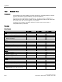
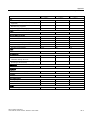
Performance features .............................................................................................................. 12-1
General Specifications ............................................................................................................. 12-1
Legal characters ...................................................................................................................... 12-1
System limits ............................................................................................................................ 12-2
Index
WinCC flexible 2005 Micro
User's Manual, Edition 06/2005, 6AV6691-1AA01-0AB0
ix
Table of contents
x
WinCC flexible 2005 Micro
User's Manual, Edition 06/2005, 6AV6691-1AA01-0AB0
1
Introduction to WinCC flexible Micro
1.1
1.1
Components of WinCC flexible
WinCC flexible Micro
WinCC flexible Micro is the smallest edition of the WinCC flexible Engineering Systems. In
WinCC flexible Micro you create and edit projects for systems containing HMIs of the Micro
Panel family. The functionality of WinCC flexible Micro edition is tailor-made for the devices
mentioned earlier.
You can upgrade to larger editions from the "Micro" edition. Projects created with the "Micro"
edition can also be edited in the more comprehensive editions of WinCC flexible.
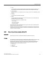
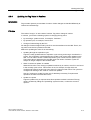
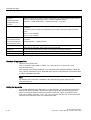
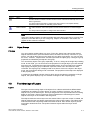
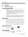
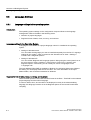
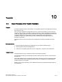
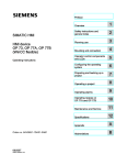
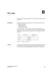
Functional scope of the individual editions
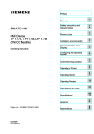
WinCC flexible is available in the following editions:
:LQ&&IOH[LEOH$GYDQFHG
:LQ&&IOH[LEOH6WDQGDUG
:LQ&&IOH[LEOH&RPSDFW
:LQ&&IOH[LEOH0LFUR
6,0$7,&3$1(/
0LFUR
6,0$7,&3$1(/
6,0$7,&3$1(/
3&EDVHG
:LQGRZV
:LQGRZV;3
The WinCC flexible editions
WinCC flexible Engineering System
WinCC flexible offers a range of scaleable engineering systems which are optimally adapted
to the respective tasks involved in configuring a variety of HMI devices and controllers. Each
edition supports a wider range of HMI devices and functions, whereby the "Standard" edition
can be used to configure HMI devices from the "Compact" edition.
WinCC flexible 2005 Micro
User's Manual, Edition 06/2005, 6AV6691-1AA01-0AB0
1-1
Introduction to WinCC flexible Micro
1.2 Configuration Support
1.2
1.2
Configuration Support
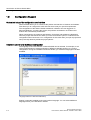
Customized setup of the configuration user interface
WinCC flexible allows you to customize the position and reaction of windows and toolbars.
This allows you to configure the work environment to meet your special requirements.
The configuration of the WinCC flexible workbench is linked to the user logged on in
Microsoft Windows. On saving the project, the positions and behavior of windows and
toolbars are automatically saved with it.
When opened again, the positions and behavior of windows and toolbars are identical to
when the project was last saved. When your work environment opens, it is identical to the
configuration when last closed. Your configuration is also used when you open a project that
was previously edited by a different project planner.
Installation options for a multilingual configuration
The language of the user interface in WinCC flexible can be selected, for example, to suit
regional requirements of several engineers of different nationality working on a project
configuration. During the installation of WinCC flexible, you select the languages to be later
available.
Language selection in WinCC flexible Setup
English is generally installed as the user interface language. You can select additional
languages when you install WinCC flexible.
1-2
WinCC flexible 2005 Micro
User's Manual, Edition 06/2005, 6AV6691-1AA01-0AB0
WinCC flexible Engineering System
2.1
2.1
2
Basic Principles on the Programming Interface
Principle
WinCC flexible is the HMI software for future-proof machine-oriented automation concepts
with comfortable and highly efficient engineering.
To start WinCC flexible, either click the desktop icon on the programming device or select it
from the Windows Start menu.
Desktop icon
WinCC flexible only allows one project to be open for editing at any time. If projects should
be copied globally, for example, restart WinCC flexible and then open the required project.
WinCC flexible 2005 Micro
User's Manual, Edition 06/2005, 6AV6691-1AA01-0AB0
2-1
WinCC flexible Engineering System
2.2 WinCC flexible user interface
2.2
2.2.1
2.2
WinCC flexible user interface
WinCC flexible User Interface Elements
Introduction
The WinCC flexible work environment consists of several elements. Some of the elements
are linked to specific editors which means they are not visible unless the corresponding
editor is active.
WinCC flexible provides a special editor for each configuring task. For example, you
configure the GUI of an HMI device in the "Screens" editor. Or you can use the "Discrete
Alarms" editor to configure alarms.
Note
Set the configuration computer operating system to "Small Fonts" while working with
WinCC flexible.
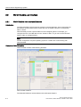
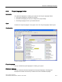
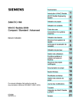
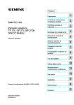
Elements of WinCC flexible
WinCC flexible consists of the following elements:
WinCC flexible workbench
The illustrated elements are described in the subsequent chapters.
2-2
WinCC flexible 2005 Micro
User's Manual, Edition 06/2005, 6AV6691-1AA01-0AB0
WinCC flexible Engineering System
2.2 WinCC flexible user interface
2.2.2
Menus and Toolbars
Introduction
The menus and toolbars provide access to all functions you need to configure your HMI
device. When an editor is active, menu commands and toolbars specific to that editor
appear.
When the mouse pointer is moved over a command, the corresponding ToolTip appears.
Tooltip
Positioning the Toolbars
Menus and toolbars are positioned by default at the top edge of the screen when a new
project is created. The position of menus and toolbars is determined by the user who is
logged on in Windows. If the toolbars are moved using the mouse, they revert back to their
last ‘Exit’ position when WinCC flexible is restarted.
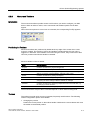
Menus
Menus available in WinCC flexible:
Menu
Brief description
"Project"
Contains commands for project management.
"Edit"
Contains commands for clipboard and search functions.
"View"
Contains commands for opening / closing elements, and for zoom / layer
settings. To reopen a closed element, select the "View" menu.
"Paste"
Contains commands for pasting new objects
"Format"
Contains commands for organizing and formatting screen objects.
"Tools"
Contains commands for changing the user interface language and
configuring the basic settings in WinCC flexible, for example.
"Window"
Contains commands for managing multiple windows in the work area, e.g.
for changing to other windows.
"Help"
Contains commands for calling help functions.
The menus and the scope of their commands depend on which editor is being used.
Toolbars
The toolbars provide quick access to important, frequently used functions. The following
toolbar configuration options are available:
• Changing the position
Position the mouse pointer on the toolbar handle. Hold down the mouse button and move
the toolbar to the desired position.
WinCC flexible 2005 Micro
User's Manual, Edition 06/2005, 6AV6691-1AA01-0AB0
2-3
WinCC flexible Engineering System
2.2 WinCC flexible user interface
2.2.3
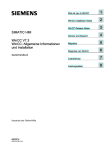
Work area
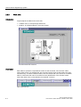
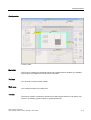
Introduction
Project objects are edited in the work area:
• in tabular form, for example tags and alarms.
• graphics, for example objects in a process screen.
Process screen TP 170micro
Description
Each editor is opened in a separate tab control on the work area. The "Screens" editor
shows each screen in a separate tab. Only one tab is active when several editors are open
simultaneously. To select a different editor, click the relevant tab in the work area. In tabular
editors, a tab shows the name of the editor for easy identification. The "Screens" editor
shows the name of the current element, for example, "Screen1."
Tabs in the work area
2-4
WinCC flexible 2005 Micro
User's Manual, Edition 06/2005, 6AV6691-1AA01-0AB0
WinCC flexible Engineering System
2.2 WinCC flexible user interface
Navigation arrows
If the work area runs out of space to show all tabs, the navigation arrows become active in
the work area.
To access tabs which are no longer visible in the work area, click the corresponding
navigation arrow.
Closing the editor
To close an editor, click the
2.2.4
symbol in the work area.
Project View
Introduction
The project view is the central control point for project editing. The project view shows all
components and editors of a project, and can be used to open these. Each editor is assigned
a symbol which you can use to identify the corresponding objects. In the project view, you
also have access to the device settings of the HMI device, the language settings and the
output view.
Description
The project view visualizes the project structure:
• Process screens in the "Screens" folder
• Editors for editing the objects of a project
• Device settings for the HMI device
• Language support and the output view
The project view is used to create and open objects for editing. Shortcut menus containing
the most important commands are available for all elements in the project view. You can also
open an editor by double-clicking the corresponding item in the project view.
WinCC flexible 2005 Micro
User's Manual, Edition 06/2005, 6AV6691-1AA01-0AB0
2-5
WinCC flexible Engineering System
2.2 WinCC flexible user interface
2.2.5
Property view
Introduction
The property view is used to edit the properties of an object selected from the work area.
The content of the property view is based on the selected object. The property view is only
available in specific editors.
Property view
Description
The property view shows the properties of the selected object organized in categories. The
changed values take effect directly after exiting from the input field.
Invalid entries are highlighted with a colored background. A ToolTip will appear to help you
correct the entry.
2.2.6
Output View
Usage
The output view displays system alarms generated, for example, in a project test run or
during the consistency check of a project.
Output View
2-6
WinCC flexible 2005 Micro
User's Manual, Edition 06/2005, 6AV6691-1AA01-0AB0
WinCC flexible Engineering System
2.3 Working with the Mouse
Description
The output view normally displays system alarms in the order they occur. Different symbols
are used to identify system alarms as notifications, warnings or faults. Using the context
menu, for example, you can jump to the location of an error or delete the system alarms in a
specific category. The categories define the corresponding WinCC flexible module which has
generated a system alarm. For example, system alarms for the "Compiler" category are
generated during the consistency check.
To sort system alarms, click the header of the corresponding column. The context menu can
be used to jump to an error location or a tag, and copy system alarms to the clipboard or
delete them.
The output view shows all system alarms of the last action. A new action overwrites all
previous system alarms.
2.3
2.3
Working with the Mouse
Introduction
Work is mainly completed with the mouse in WinCC flexible. Important operating functions in
this context are the drag-and-drop function and the call of commands from the shortcut
menu.
Drag-and-drop
Drag-and-drop makes configuration much easier. To configure a screen change, drag-anddrop the required process screen onto the process screen shown in the work area. This
generates a button configured to contain a corresponding screen change function.
The drag-and-drop function is available for all objects in the project view and "Object view."
The mouse pointer shows you whether drag-and-drop is supported at the destination or not:
•
Drag-and-drop is possible
•
Drag-and-drop is not possible
Shortcut menu
In WinCC, you can right-click any object to open a shortcut menu. The shortcut menu
contains the commands you can execute in the relevant situation.
WinCC flexible 2005 Micro
User's Manual, Edition 06/2005, 6AV6691-1AA01-0AB0
2-7
WinCC flexible Engineering System
2.4 Keyboard control
Overview: Mouse functions
2.4
2.4
Function
Effect
Left-click
Activates any object or executes an action such as a menu
command or drag-and-drop.
Right-click
Opens a shortcut menu.
Double-click (left mouse button)
Starts an editor in the project view.
<Left mouse button+drag-and-drop>
Generates a copy of the object in the project view.
Keyboard control
Introduction
WinCC flexible provides a number of hotkeys which you can use to execute frequently
required menu commands. The menu shows whether a hotkey is available for the relevant
command or not.
WinCC also integrates all the standard hotkeys provided by Windows.
Important hotkeys
The table shows you the most important hotkeys for use in WinCC flexible.
2-8
Hotkeys
Effect
<Ctrl+Tab>/<Ctrl+Shift+Tab>
Activates the next/previous tab in the work area.
<Ctrl+F4>
Closes the active view in the work area.
<Ctrl+C>
Copies a selected object to the clipboard.
<Ctrl+X>
Cuts an object and copies it to the clipboard.
<Ctrl+V>
Inserts the object stored in the clipboard.
<Ctrl+A>
Selects all objects in the active area.
<ESC>
Cancels an action.
WinCC flexible 2005 Micro
User's Manual, Edition 06/2005, 6AV6691-1AA01-0AB0
WinCC flexible Engineering System
2.5 Working with WinCC flexible
2.5
2.5
2.5.1
Working with WinCC flexible
Displaying Help
Shortcut help
A tooltip will appear after moving the mouse pointer over any object, icon, or dialog element.
A question mark next to the tooltip indicates that a shortcut help is available for this user
interface element. To call up an additional explanation to the short description, click on the
question mark, press <F1> if the tooltip is activated, or move the mouse cursor to the tooltip.
The explanation includes references which refer users directly to a detailed description in the
online help.
Online help
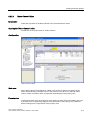
In the "Help" command menu you can access the online help. When you use the "Help >
Contents" menu command, the WinCC flexible Information System opens with an opened
table of contents. Use the table of contents to navigate to the desired topic.
Alternatively select the "Help > Index" menu command. The WinCC flexible Information
System opens with an opened index. Use the index to search for the desired topic.
In order to use the full text search across the entire WinCC flexible Information System
select the "Help > Search" menu command. The WinCC flexible Information System opens
with a search tab. Enter the desired search term.
The WinCC flexible Information System can also be opened via the Start menu in Windows.
Select the menu command "Start > SIMATIC > WinCC flexible > WinCC flexible Help
System" in the task bar.
The Online Help system is opened in a separate window. The WinCC flexible Portal opens
on the home page. The WinCC flexible Portal is organized by topical overviews. The
overview topics contain cross-references to subordinate topics which bring you directly to the
information you are looking for.
WinCC flexible 2005 Micro
User's Manual, Edition 06/2005, 6AV6691-1AA01-0AB0
2-9
WinCC flexible Engineering System
2.5 Working with WinCC flexible
2.5.2
Editor Properties
Introduction
WinCC flexible provides a special editor for each configuring task. WinCC flexible
differentiates between two different types of editors: the "Screens" editor as a graphical
editor and the tabular editors such as the "Tags" editor.
Screen editor
The "Screens" editor shows all of the screens contained in the project in the project view of
the "Screens" folder. All screens are opened in a separate window in the work area.
Tabular editors
Tabular editors, such as the "Tags" editor, only display the objects contained in the work
area. The objects contained there are displayed in a table. You can edit the objects either
directly in the table or in the property view.
Editor properties
The following properties apply to all editors and their objects:
• Changing contents
Changes take effect directly after exiting an input field and affect projects globally. All the
objects affected by a modification are automatically updated.
If a tag parameter is changed in the "Screens" editor, for example, the change has a
direct effect in the "Tags" editor.
• Accepting changes to the project data
The modified project data are transferred to the project database as soon as the project is
saved.
• Undo or redo working steps
Every editor has an internal list in which user actions are saved. In this way, all actions
can be reverted (undone) or restored. The relevant commands are in the "Edit" menu.
The list is deleted when the editor is closed or the project is saved. Switching to another
editor does not affect the actions stored in the list.
2-10
WinCC flexible 2005 Micro
User's Manual, Edition 06/2005, 6AV6691-1AA01-0AB0
WinCC flexible Engineering System
2.5 Working with WinCC flexible
2.5.3
Opening an Editor
Introduction
There are several ways to start the editors in WinCC flexible. These options vary, depending
on the editor involved. You can open up to 20 editors in parallel.
Opening the "Screens" editor
The "Screens" editor is started by either creating a new object or opening an existing object.
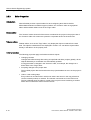
To create a new object, proceed as follows:
1. Click on "Screens" in the project view with the right mouse button.
2. Select "Add Screen" from the shortcut menu.
Shortcut menu
A new screen is created in the project view and displayed in the work area.
To open an existing screen, double-click on the screen in the project view. The screen opens
in the work area.
WinCC flexible 2005 Micro
User's Manual, Edition 06/2005, 6AV6691-1AA01-0AB0
2-11
WinCC flexible Engineering System
2.5 Working with WinCC flexible
Opening a tabular editor
A tabular editor such as the "Tags" editor is opened by double-clicking on the tabular editor
in the project view. The editor then appears in the work area.
A tabular editor can also be activated using the associated shortcut menu.
Alternative procedure
To open an editor from a menu, select the "Project Item" command from the "Insert" menu.
2.5.4
Editing Multiple Projects with WinCC flexible
Principle
WinCC flexible only allows one project to be open for editing at any time. If you wish to copy
projects globally, restart WinCC flexible and then open the desired project.
Each opened WinCC flexible is shown in the Windows task bar:
2-12
WinCC flexible 2005 Micro
User's Manual, Edition 06/2005, 6AV6691-1AA01-0AB0
WinCC flexible Engineering System
2.5 Working with WinCC flexible
2.5.5
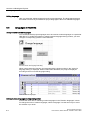
Object list
Introduction
The object list is a helpful feature for configuration tasks in WinCC flexible. You can use the
object list to find an existing object of the required object type and configure it directly at the
place of use. You can also use the object list to create new objects at the place of use.
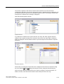
Opening the object list
Objects are usually edited in the property view but can also be edited directly in the table in
the work area when tabular editors are used. If WinCC flexible needs a connection to an
object, the object list opens when you click on the object selection list. When, for example,
you wish to configure a tag for the graphic object, click in the selection field for the tag. From
the selection field, the object list opens offering you all of the available tags with suitable data
type in the project for selection.
Object list
Select the required tag. Confirm your selection by pressing the
button.
Working with object lists
When a suitable object is not available in the project, create a new one using the object list.
To create a new object, click on the "New" button in the object list.
A new object is created and the corresponding dialog for configuring this object opens.
Configure the newly created object and close the configuration dialog.
You can also open and configure an existing object from the object list. Select the object
from the object list. The
icon for editing is displayed in the right column. Click on the
icon. The corresponding dialog for editing the object opens. Edit the properties of the object
and close the configuration dialog.
WinCC flexible 2005 Micro
User's Manual, Edition 06/2005, 6AV6691-1AA01-0AB0
2-13
WinCC flexible Engineering System
2.5 Working with WinCC flexible
2.5.6
Function List
Introduction
A function list is an attachment of system functions, which are executed successively when
calling the function list. You can use the function list to trigger the execution of system
functions at an event. The function list is configured for an event of an object, e.g. a screen
object or a tag. The events which are available depend on the selected object. Events occur
only when the project is in runtime. Events are, for example:
• Value changes of a tag
• Pressing of a button
• Alarm occurrences
You can configure a function list precisely on every event. Up to 16 functions may be
configured in a function list. When the configured event occurs in runtime, the function list is
completed from top to bottom. In order to avoid waiting times, system functions with a longer
running time, file operations, for instance, are processed simultaneously. A subsequent
system function can be performed even if the previous system function has not yet been
completed.
Configure function list
In WinCC flexible, open the editor containing the object for which you wish to configure the
function list. Select the object with the mouse. In the property view, click on the event in the
"Events" groups on which you want to configure the function list. The function list opens in
the property view.
Function List
2-14
WinCC flexible 2005 Micro
User's Manual, Edition 06/2005, 6AV6691-1AA01-0AB0
WinCC flexible Engineering System
2.5 Working with WinCC flexible
"No function" appears in the first line of the function list when no function has been
configured for the object. Click on the "No function" field. A selection button is displayed. Use
the selection button to open the list of available system functions. The system functions are
arranged in the selection list according to categories.
Select the desired system function.
System functions
If a parameter is needed for the system function, the entry "No value" appears after the
selection of the system function in the next line. Click on the "No value" field. A selection
button is displayed. Use the selection button to open the object list and select the required
parameter.
Parameter selection
The function is configured in the function list. Configure other functions as required. Using
the arrow buttons
and
change the sequence of the configured functions/scripts.
Select a function and move the function up or down by clicking on the arrow buttons. To
delete a function, mark the function with the mouse and press the <Del> key.
WinCC flexible 2005 Micro
User's Manual, Edition 06/2005, 6AV6691-1AA01-0AB0
2-15
WinCC flexible Engineering System
2.6 WinCC flexible Start Center
2.6
2.6
WinCC flexible Start Center
Introduction
With WinCC flexible 2005 you can open projects more quickly. For the quick start, certain
services for WinCC flexible are launched in the background while the operating system is
booting. To operate the WinCC flexible Start Center, during the installation a symbol is
created in the Taskbar Notification Area, the so-called Tray area of the taskbar.
Start Center Symbol
WinCC flexible Start Center Menu Commands
The popup menu for operating the Start Center is opened with a right mouse click on the
symbol in the Tray area of the taskbar. This includes the following menu commands:
Menu command
Function
Run SIMATIC WinCC flexible
Starts WinCC flexible and opens the project wizards.
SIMATIC WinCC flexible Auto Start ►
Activate
Enables the quick start of WinCC flexible, necessary services for the quick
start are loaded during start-up of the operating system.
SIMATIC WinCC flexible Auto Start ►
Deactivate
Disables the quick start for WinCC flexible, no additional services are
launched during start-up of the operating system.
Help
Opens the WinCC flexible Start Center online help.
Info...
Opens a window displaying the version information for the Start Center.
Stop
Ends the Start Center.
Run WinCC flexible
During the installation of WinCC flexible, WinCC flexible Start Center is also automatically
installed and enabled. Restart the computer in order for Start Center to take effect. To start
WinCC flexible, select "Run WinCC flexible" from the the shortcut menu of the Start Center.
Alternatively, launch WinCC flexible by clicking the desktop icon. This activates WinCC
flexible and opens the Project Wizard. The Project Wizard supports you in further
procedures.
Disable Start Center
To disactivate the WinCC flexible Start Center, select "SIMATIC WinCC flexible Auto Start ►
Disable" from the shortcut menu of the WinCC flexible Start Center. After the next restart of
your the computer, no more WinCC flexible components will be launched in the background.
2-16
WinCC flexible 2005 Micro
User's Manual, Edition 06/2005, 6AV6691-1AA01-0AB0
3
Working with Tags
3.1
3.1.1
3.1
Basics
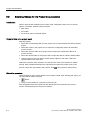
External tags
Introduction
External tags enable the communication (data exchange) between the components of an
automation process, e.g. between the HMI device and the PLC.
Principle
An external tag is the image of a defined memory location in the PLC. You have read and
write access to this storage location from both the HMI device and the PLC.
Since external tags are the image of a storage location in the PLC, the applicable data types
depend on the PLC which is connected to the HMI device.
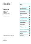
Data types
SIMATIC S7-200
Name
Object
Data type
Tag
V
Char, Byte, Int, Word, DInt, DWord, Real, Bool, StringChar
input
E
Char, Byte, Int, Word, DInt, DWord, Real, Bool, StringChar
Output
A
Char, Byte, Int, Word, DInt, DWord, Real, Bool, StringChar
Flag
M
Char, Byte, Int, Word, DInt, DWord, Real, Bool, StringChar
Timer
T
Timer
Counter
C
Int
Using area pointers
In addition to the external tags, the area pointer "Date/Time PLC" can be used for
communication between the HMI device and PLC. The area pointer is used to display the
time of the PLC on the HMI device. For further information, refer to the description on the
"Connections" editor in this documentation.
WinCC flexible 2005 Micro
User's Manual, Edition 06/2005, 6AV6691-1AA01-0AB0
3-1
Working with Tags
3.2 Elements and basic settings
3.1.2
Internal Tags
Introduction
Internal tags do not have any connection to the PLC.
Principle
Internal tags are stored in the memory of the HMI device. Therefore, only this HMI device
has read and write access to the internal tags. You create internal tags, for example, in order
to execute local calculations.
The following data types are available for internal tags.
Char, Byte, Int, Uint, Long, Ulong, Float, Double, Bool, String and DateTime.
3.2
3.2.1
3.2
Elements and basic settings
"Tag" Editor
Introduction
Tags are created in the "Tags" editor. The tag is assigned a basic configuration when it is
created. You can use the "Tags" editor to adapt the configuration of the tag to the
requirements of your project.
Open
Open the "Tag" editor by selecting the "Tags" item in the project view, then right-click to
open the shortcut menu. Select this shortcut menu command:
• Open Editor
or
• Add Tag
You can also open the "Tag" editor by double-clicking the "Tags" item in the project view.
3-2
WinCC flexible 2005 Micro
User's Manual, Edition 06/2005, 6AV6691-1AA01-0AB0
Working with Tags
3.2 Elements and basic settings
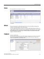
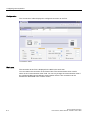
Structure
The "Tags" editor shows all tags of the project.
"Tag" Editor
Work area
All tags are displayed in a table in the work area. You can sort the table according to the
entries in a column by clicking on the column header.
You can configure the selection of columns to suit your needs. Move the mouse pointer to a
column header and open the context menu by clicking the right mouse button. In the shortcut
menu, select which of the columns is to be shown or hidden. The column selection is saved
automatically when you save the project. It is linked to the user name that you used when
logging on to Microsoft Windows.
Property view
Here you configure tags.
The left section of the property view shows a variety of categories from which you can select
the various subcategories. The fields for configuring the selected property category are
shown in the right section of the property view.
Tag property view
WinCC flexible 2005 Micro
User's Manual, Edition 06/2005, 6AV6691-1AA01-0AB0
3-3
Working with Tags
3.2 Elements and basic settings
3.2.2
Basic tag settings
Introduction
You can configure the properties of tags in the property view, or directly in the respective
table cell in the work area.
Structure of the property view
The left sections of all property views show a variety of categories from which you can select
the various subcategories. The fields for configuring the property category are shown in the
right section of the property view.
Property view for tags
Tag property view
3-4
WinCC flexible 2005 Micro
User's Manual, Edition 06/2005, 6AV6691-1AA01-0AB0
Working with Tags
3.2 Elements and basic settings
You can configure the following properties of the selected tag in the property view for tags:
Category
Fields
"General"
"Name"
"Connection"
"Data type"
"Acquisition type"
"Acquisition cycle"
"Array count"
"Length"
"Properties"
"Addressing"
(for external tags only)
"VW"
"IW"
"QW"
"MW"
"C"
"T"
"Limits"
"Hi limit - deactivated"
"Hi limit constant"
"Lo limit - deactivated"
"Lo limit constant"
Limit check
"Basic settings"
"Update code"
"Comment"
Text field for entering the comment
"Events"
"Hi limit exceeded"
List of functions that will be processed if the hi limit is exceeded
"Value change"
List of functions that will be processed if the process value
changes
"Lower limit exceeded"
List of functions that will be processed if the value drops below
the lower limit
WinCC flexible 2005 Micro
User's Manual, Edition 06/2005, 6AV6691-1AA01-0AB0
3-5
Working with Tags
3.3 Working with Tags
3.3
3.3.1
3.3
Working with Tags
Properties of a Tag
Introduction
In WinCC flexible, certain properties can be configured for every tag.
The properties determine how you can use the tag in your configuration.
Principle
The following properties can be configured for tags:
• Name
Every tag has a name which you can choose. The name must be unique within the
project.
• Connection
Create a connection to the PLC for external tags. An external tag is used as an image of
the memory area in the PLC and saves the value that is passed from the PLC.
• Data type and length
The data type of a tag determines which type of values will be stored in a tag, how these
are saved internally and the maximum value range that can be held by the tag.
Two simple examples of data types are "Int" for saving integers or "String" for saving
character strings.
For text tags of the type "String" or "StringChar", you can also set the length of the tag in
bytes. For all other data types, the value of "Length" is fixed.
• Acquisition type
At the acquisition type parameter, you define how the value of an external tag is updated.
Update methods available:
– On request
– Cyclic on use
– Cyclic continuous
• Acquisition cycle
By setting the acquisition cycle, you can determine how often and when a tag is updated.
• Array count
Create a tag array consisting of several elements of the same type to save large volumes
of data of the same type. Array elements occupy a continuous address area. A complex
tag containing array elements is referred to as an array tag.
• Address
An external tag represents a Runtime image of a specific memory area in the CPU. You
define the memory area the tag should map.
3-6
WinCC flexible 2005 Micro
User's Manual, Edition 06/2005, 6AV6691-1AA01-0AB0
Working with Tags
3.3 Working with Tags
• Limits
You can specify a value range that contains an upper and lower limit for each tag. You
can use limits to monitor the value range of a process value configured for the tag.
• Update identifier
Using the update ID, you update the value of a tag by means of the "UpdateTag" system
function.
• Comment
You can enter a comment for every tag.
• Events
You can configure a function list for an event. The function list is processed when the
configured event occurs in Runtime.
The following data types are available for tags.
– Value change
– Upper limit exceeded
– Lower limit violated
All properties which were configured when the tag was created can be modified with the
object list later where the tag is used.
Example: Create a tag and configure its limit values. Link this tag to an IO field. The limit
values which were set when the tag was created can be modified with the object list later
when the IO field is configured.
3.3.2
External Tags for Communication with the PLC
Introduction
External tags are used to exchange data between an HMI device and PLC.
Principle
An external tag is used as an image of a defined memory area in the PLC. You have read
and write access to this storage location from both the HMI device and the PLC.
The fact that the HMI device can access data on the PLC affects which properties are
available when you configure the tags. The following tag properties depend on the
configuration options in the properties of the PLC:
• "Addressing"
• "Data type"
• "Acquisition cycle"
WinCC flexible 2005 Micro
User's Manual, Edition 06/2005, 6AV6691-1AA01-0AB0
3-7
Working with Tags
3.3 Working with Tags
Addressing
If you create an external tag in WinCC flexible, you must specify the same address as it has
in the PLC program. This enables both the HMI device and the PLC to access the same
memory location.
Example: You would like to visualize the status at the PLC output "A 1.2" on your HMI. To do
this, create an external tag and set the output "A 1.2" as the address.
Acquisition cycle
The acquisition cycle determines when the HMI device will read the process value of an
external tag. Normally, the value is updated at regular intervals as long as the tag is shown
in the process screen. The interval for regular updates is set with the acquisition cycle. You
can either choose a default acquisition cycle, or define a user-specific cycle. The shortest
cycle time of the SIMATIC S7-200 PLC is 100 ms.
The update, however, can also be carried out continuously independent on the view in a
process image. Please note that frequent read operations increase communication load.
3.3.3
Tag limit values
Introduction
You can define a value range for numerical tags.
Principle
You can specify a hi and lo limit of the range of values for numerical tags.
When a process value violates one of the limits, you can execute a function list.
Configure the limit values and the function list directly at the tag.
Application example
Use limit values to open a process screen where the operator can edit this value.
3-8
WinCC flexible 2005 Micro
User's Manual, Edition 06/2005, 6AV6691-1AA01-0AB0
Working with Tags
3.3 Working with Tags
3.3.4
Updating the Tag Value in Runtime
Introduction
Tags contain dynamic process data of runtime. Value changes are handled differently at
internal and external tags.
Principle
The value of a tag is "0" at the start of runtime. Tag values change in runtime.
In runtime, you have the following options of changing the tag value:
• by executing a system function, for example, "SetValue."
• by operator input, for example, at an IO box
• Change of external tags by the PLC
All changes of external tags made by the PLC must be transferred to the HMI. That is, the
tag value must also be updated on the HMI.
Method for updating the value of an external tag:
• Updating through an acquisition cycle
Tags are usually updated after an acquisition cycle as long as the tag is visualized in a
screen. The acquisition cycle determines the update cycle for tag value updates on the
HMI. You can either choose a default acquisition cycle, or define a user-specific cycle.
The lowest value is determined by the HMI used. The values of all other cycles are
always an integer multiple of the smallest value.
• When "Continuous update" is enabled
When this function is set, the tag is updated continuously in runtime, even if it is not found
in the currently open screen. This function is set, for example, for tags which are
configured to trigger a function list in the event of a change in their value. The cycle time
configured for the tag is also used for continuous updates.
Use the "Continuous update" function only if absolutely necessary. Frequent read
operations increase communication load.
• Update on request
Tags are updated only on request when this acquisition method is selected. The tag
value is updated by calling the "UpdateTag" system function, or when the screen is
opened.
WinCC flexible 2005 Micro
User's Manual, Edition 06/2005, 6AV6691-1AA01-0AB0
3-9
Working with Tags
3.4 Array basics
3.4
3.4
Array basics
Introduction
Create a tag array consisting of several elements of the same type to save large volumes of
data of the same type. Array elements occupy a continuous address area.
A complex tag containing array elements is referred to as an array tag.
Principle
Array tags consist of a configurable number of array elements in which data of the same type
can be stored. Each array tag element requires the same memory space. All array tag
elements are saved consecutively in memory.
Note
Read and write operations always access all array tag elements. The contents of an array
tag which is interconnected with a PLC are always transferred whenever there is a change.
This is why the HMI device and the PLC can not concurrently write access the same array
tag.
Array element properties
The various array elements inherit their properties of the array tag. Array element properties
include, for example, the first segment of its name, its data type or its length.
3-10
WinCC flexible 2005 Micro
User's Manual, Edition 06/2005, 6AV6691-1AA01-0AB0
Working with Tags
3.5 Cycle basics
3.5
3.5
Cycle basics
Introduction
Cycles are used to control project sequences that are run at regular intervals. A cycle is
configured with a cycle time that determines the time intervals repeated within the cycle.
Principle
In runtime, actions that are performed at regular intervals are controlled by cycles. A typical
cycle application is the acquisition of external tags.
• Acquisition cycle
The acquisition cycle determines the intervals for the HMI to read the process value of an
external tag from the PLC. Set the acquisition cycle to suit the rate of change of the
process values. The temperature of an oven, for example, changes much more slowly
than the speed of an electrical drive.
If the acquisition cycle is set too low, it will unnecessarily increase the communication
load of the process.
The lowest value for a cycle depends on the HMI used. For HMIs of the Micro Panel family,
the lowest value is 100 ms. The values of all other cycles are always an integer multiple of
the smallest value.
Application example
You can use cycles, for example, to regularly update the process value display.
WinCC flexible 2005 Micro
User's Manual, Edition 06/2005, 6AV6691-1AA01-0AB0
3-11
Working with Tags
3.6 Importing Tags
3.6
3.6.1
3.6
Importing Tags
Importing Tags in WinCC flexible
Introduction
WinCC flexible 2005 supports the import of tags from an external data source. To
successfully complete an import, the data to import must meet requirements described in this
chapter. You export the tag data from a PLC program to an Excel file. The exported data
must be prepared according to rules, and can then be imported in WinCC flexible. Certain
applications are available to prepare tag data of PLC programs, and o prepare the exported
PLC data for import in WinCC flexible. The latest versions of these applications can be be
downloaded from the Internet at:
"http://support.automation.siemens.com/WW/view/en/16502367/133100"
Tag import procedures
To import all tag data, you need a file to which you can first save these data. You import this
file in WinCC flexible. Before you run the import, you can decide whether or not to overwrite
existing tags of the same name.
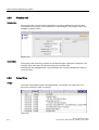
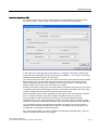
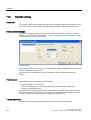
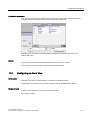
3.6.2
Settings for the Tag Import
Introduction
The "Import tags to device" dialog box is can be used to import tags. Make all required
settings in this dialog box to ensure the import files can be correctly interpreted.
3-12
WinCC flexible 2005 Micro
User's Manual, Edition 06/2005, 6AV6691-1AA01-0AB0
Working with Tags
3.6 Importing Tags
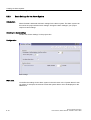
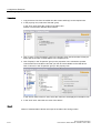
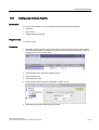
Importing tags to an HMI
To open the "Import tags to device" dialog, select the relevant HMI in the project window,
then select "Project > Import Tags." Click "Options" to define the import settings.
In the "Files" area, enter the path of the import file, or navigate to the folder containing the
file to select the required file. The import file must be available in "*.csv" format. The system
validates the file names before it runs the import.
You cannot make any entries in the "File name for connection" field, because WinCC flexible
Edition "Micro" only communicates with PLCs of the S7 200 series. Prerequisite for the
import of tag data is that you have configured a connection to the PLC. In the import file,
always use the correct name of the connection you created.
Existing connections or tags of the same name will be overwritten during import if you set the
"Overwrite the existing connection/tag" check box. Connections and tags of the same name
in WinCC flexible will not be imported when this check box is reset.
Select a separator for the various parameters of the tags from the "List separator" selection
box. For further information, refer to the chapter "Tag data format for the import."
The text qualifier is used to identify text and strings. Any quoted characters will be
interpreted as text. Any control characters in the text you want to import should be quoted.
Quotation marks are the default text qualifiers, and may not be replaced by other characters.
You can define the decimal and thousands separators to identify numeric data. Select a
character from the relevant selection box. Those two characters may not be identical. It is
not allowed to use quotation marks as separator.
The "Use folder separators" function is disabled, because WinCC flexible "Micro" does not
support any folder structures for storing tags.
WinCC flexible 2005 Micro
User's Manual, Edition 06/2005, 6AV6691-1AA01-0AB0
3-13
Working with Tags
3.6 Importing Tags
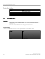
3.6.3
Format of the Connection Data for the Import
Introduction
This section describes the format required for the file with connection data used for imports.
The connection data file must be in "*.csv" format.
Format of Connection Data
Each connection is on a separate line in the import file. The import file with the connection
data must have the following format:
<Name of connection><list separator character><Name of communication driver><list
separator character><Comment><Line break (carriage return)>
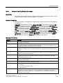
Meaning of the entries
List entry
Meaning
Connection name
Defines the configured name of a connection. This entry is needed to match up to the
corresponding entry in the import file of the tags. The "Name" list entry may not be blank.
The name may not contain an apostrophe (').
List separator
The list separator is used to separate the various list entries. You can select the list
separators in the import dialog box. Selectable characters: Semicolon ";", comma "," and
period ".". You may also enter a different character in the selection field.
Name of the communication
driver
Specifies the name of the communication driver used in WinCC flexible. It must exactly
match the name used in WinCC flexible. The following names are available:
• SIMATIC S7 200
Comment
Any comment about the connection. Comments may have length of 500 characters.
Line break
The line break (carriage return) separates the connection entries.
Format of the Import File for Connections
An import file for connections has the following format:
connection, "SIMATIC S7 200", connection example
This example uses comma separation. Two consecutive list separators indicate a blank list
entry. The list separators may be discarded at the end of a completed line.
Note
An example of an import file is available in the "Support\Tag Import" folder on your
WinCC flexible CD.
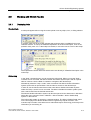
Editing the import file
You can edit the import file in MS Excel, or in any text editor. Do not open the import file in
MS Excel by double-clicking it, because this will corrupt its data structure and prevent its
import. You should rather run MS Excel, and then select the "Open" command from the
"File" menu. Select "Text files" (*.prn; *.txt; *csv)" from the "File type" list. To verify the data
structure of the import file, open it in a simple text editor.
3-14
WinCC flexible 2005 Micro
User's Manual, Edition 06/2005, 6AV6691-1AA01-0AB0
Working with Tags
3.6 Importing Tags
3.6.4
Format of the Tag Data for the Import
Introduction
This chapter describes the structure of the file containing the tag data for the import. The file
containing the tag data file must be available in "*.csv" format.
Structure of tag data
Each tag is assigned a separate line in the import file. Structure of the import file containing
the tag data:
<Tag name><list separator character><Connection name><list separator character><Tag
address><list separator character><Data type><list separator character><Tag length [in
bytes]><list separator character><Number of arrays><list separator character>< Acquisition
mode><list separator character><Acquisition cycle><list separator character><High
limit><list separator character><Additional high limit><list separator character><Additional
low limit><list separator character><Low limit><list separator character><Linear scaling><list
separator character><Scaling high limit PLC><list separator character><Scaling low limit
PLC><list separator character><Scaling high limit HMI><list separator character><Scaling
low limit HMI><list separator character><Start value><list separator character><Update
ID><list separator character><Comment><line break (carriage return)>
Meaning of the entries
List entry
Meaning
Tag name
Defines the configured name of a tag. The "Name" list entry may not be blank. The name may
not contain an apostrophe (').
List separator
The list separator is used to separate the various list entries. You can select the list separators
in the import dialog box. Selectable characters: Semicolon ";", comma "," and period ".". You
may also enter a different character in the selection field.
Connection name
Defines the configured name of a connection. Each external tag should contain a valid entry
showing the connection name. The system generates an internal tag if the connection name is
not set.
Tag address
Defines the tag address in the PLC. The syntax of the tag address must match the
representation in WinCC flexible, for example, "DB 1 DBW 0", but not "DB1, DBW0." The tag
address is not defined for internal tags.
Data type
Defines the data type of the tag. Which data types are permitted is determined by the
communication driver used. Supported values are Char, Byte, Int, Bool, String, Word, Dint,
DWord , Real, StringChar, Timer.
Tag length [in bytes]
Defines the length of the tag in bytes. This entry is usually made only for string tags; for other
data types it remains blank.
Number of arrays
Defines the number of arrays in a tag. This value can be used to define an array.
WinCC flexible pads the blank entry with a "1" value.
Acquisition mode
Defines the acquisition mode of the tag. The acquisition mode is represented by numbers.
1 = on request
2 = cyclic, when used (default value)
3 = cyclic, continuous
Acquisition cycle
Defines the acquisition cycle of a tag. The syntax of the acquisition cycle must match the
representation in WinCC flexible. The value is independent on the language, and must be
identical in any language. Default is "1 s." The acquisition cycle is indefinite if acquisition mode
"on request" is set for the tag.
WinCC flexible 2005 Micro
User's Manual, Edition 06/2005, 6AV6691-1AA01-0AB0
3-15
Working with Tags
3.6 Importing Tags
List entry
Meaning
High limit
Limits can only be set for numeric values. You may only use constant numeric values, but not
the tags, to set limits. Default is "No limit." Conditions applicable to limits:
Additional high limit
"High limit" ≥ "Additional high limit" ≥ "Additional low limit" ≥ "Low limit"
Additional low limit
Low limit
Linear scaling1)
Defines whether to enable linear scaling. This entry is only applicable to external tags. Default
is "Disabled."
The values for linear scaling may be defined by a numerical or text-based syntax. Permitted
values:
"false" or "0" for "disabled
"true" or "1" for "enabled"
PLC Scaling high
limit1)
PLC Scaling low limit1)
HMI Scaling high limit1)
You can only set high and low limits for numerical values. Conditions applicable to the start and
end values:
"Scaling high limit" ≥ "Scaling low limit"
HMI Scaling low limit1)
Start value1)
Defines the start value of a tag. Default values: 0 for numerical values, space for characters,
empty string for string tags, actual value for the time and date.
Update ID
The Update ID indicates the tag number of a tag which has changed in the PLC.
Comment
User-specific tag comments. Comments may have length of 500 characters.
Line break
The line break (carriage return) separates the connection entries.
1) Not
supported by TP 170micro.
Structure of tag import files
Structure of tag import files:
"tag","Connection","DB 1 DBD 0","Real",,1,3,"1 min",20,10,2,1,1,100,10,10,1,15.5,
33,Comment for tag
This example uses comma separation. Two consecutive list separators indicate a blank list
entry. The list separators may be discarded at the end of a completed line. The default value
is used to pad blank list entries.
Note
An example of an import file is available in the "Support\Tag Import" folder on your
WinCC flexible CD.
Editing the import file
You can edit the import file in MS Excel, or in any text editor. Do not open the import file in
MS Excel by double-clicking it, because this will corrupt its data structure and prevent its
import. You should rather run MS Excel, and then select the "Open" command from the
"File" menu. Select "Text files" (*.prn; *.txt; *csv)" from the "File type" list. To verify the data
structure of the import file, open it in a simple text editor.
3-16
WinCC flexible 2005 Micro
User's Manual, Edition 06/2005, 6AV6691-1AA01-0AB0
Creating Screens
4.1
4.1.1
4.1
4
Basics
Screen Basics
Introduction
In WinCC flexible, you create screens which an operator can use to control and monitor
machines and plants. When you create your screens, predefined objects are available to
support you in visualizing processes and setting process values.
Application example
The figure below shows a process screen which was created in WinCC flexible. This screen
can be used to operate and monitor an oven. The operating mode can be set to "Automatic"
or "Manual" using buttons. In the "Manual" mode, the "Temp. +" and "Temp. –" buttons can
be used to change the oven temperature. The bar is an analog display of the current oven
temperature. The reference temperature is displayed in the I/O field "Set Temp" and can be
changed by input on the HMI device. The current temperature is indicated in the "Actual
Temp" output box. You can use the arrow buttons to navigate to the previous or next
process screen in a defined sequence. The button showing the house brings you to the
home screen.
Configuration examples
WinCC flexible 2005 Micro
User's Manual, Edition 06/2005, 6AV6691-1AA01-0AB0
4-1
Creating Screens
4.1 Basics
Screen design
Insert an object you need to represent a process into your screen. Configure the object to
correspond to the requirements of your process.
A screen may consist of static and dynamic elements.
• Static elements such as text do not change their status in runtime. In the example of the
oven, the labels on the digital temperature displays are static.
• Dynamic elements change their status based on the process. They visualize current
process values which are output from the memory of a PLC or HMI device, in the form of
a bar in the oven example. Operator input boxes also belong to the category of dynamic
elements.
The PLC and the operator station exchange process values and operator input data by
means of tags.
Screen properties
The layout of the screen corresponds to the layout of the user interface of the HMI device.
Properties such as the screen resolution and available fonts also depend on the selected
HMI.
4.1.2
"Screens" Editor
Introduction
You configure your screens in the "Screens" editor. This editor is formed by the combination
of a graphic programming software and a process visualization tool. You open the "Screens"
editor from the project view.
Open
Double-click "Add screen" in the "Screens" group of the project view,
The work area opens with a new screen.
4-2
WinCC flexible 2005 Micro
User's Manual, Edition 06/2005, 6AV6691-1AA01-0AB0
Creating Screens
4.1 Basics
Configuration
"Screens" Editor
Menu bar
The menu bar contains all commands required for operating WinCC flexible. Any available
shortcut keys are indicated next to the menu commands.
Toolbars
You can hide or show a specific toolbar.
Work area
You configure screens in the work area.
Toolbox
The toolbox contains a selection of simple and complex objects which you can add to your
screens, for example, graphic objects or operating elements.
WinCC flexible 2005 Micro
User's Manual, Edition 06/2005, 6AV6691-1AA01-0AB0
4-3
Creating Screens
4.1 Basics
Property view
The content of the property view is determined by the object you have currently selected in
the work area.
• When an object is selected, you can edit the properties of the selected object in the
property view.
• If you have not selected an object on the active screen, the properties of this screen are
shown and can be edited in the property view.
4.1.3
Planning the creation of screens
Procedures
To create screens, you need to take the following initial steps:
• Planning the structure of the process display: How many screens and what trees are
needed?
Example: Process partitions can be visualized in separate screens and merged in a
master screen.
• Plan the navigation between the individual screens.
• Adapt the template.
The template which is stored in WinCC flexible for the selected HMI device applies to all
your project screens. You can configure objects in the template from a central location.
Insert objects needed in every process screen into the template. You only need to
configure the properties of the objects once. The template already includes an alarm
window that shows occurring system alarms. Delete the alarm window from the template
if you do not need it. The objects configured in the template are also shown on all
process screens opened in the work area. You can disable the visualization of template
objects using the "Options > Settings > Screen Editor > Screen Editor Settings command.
• Create the screens.
4.1.4
Managing Screens
Introduction
In the project view, you can move, copy, rename and delete screens within a project.
Copy screen
You can copy a screen in WinCC flexible, for example, to use it again as a screen template.
1. Select the screen from the "project view."
2. Select the "Copy" command in the shortcut menu to copy the screen to the clipboard.
3. Select the screen folder in the project view and open the context menu.
4. Select "Paste" from the shortcut menu to paste the screen.
A copy of the screen is inserted with the same name and an incremented sequential
number.
As an option, press <CTRL> while you drag the screen to the required position.
4-4
WinCC flexible 2005 Micro
User's Manual, Edition 06/2005, 6AV6691-1AA01-0AB0
Creating Screens
4.2 Objects of the "Screens" editor
Rename screen
1. Select the screen from the "project view."
2. Select "Rename" from the shortcut menu.
3. Type in a new name.
4. Press <ENTER>.
As an option, use the <F2> function key to rename the screen.
Delete screen
1. Select the screen from the "project view."
2. Select "Delete" from the shortcut menu.
The screen and all its objects are deleted from the current project.
4.2
4.2.1
4.2
Objects of the "Screens" editor
Overview of Objects
Introduction
Objects are graphic elements which you use to design the process graphics of your project.
The "Toolbox" contains various types of objects which are frequently required for use in
process screens.
When the "Screens" editor is opened, the toolbox provides objects in the following object
groups.
• "Simple objects"
Simple objects are graphic objects such as the text box and standard operating elements,
such as an I/O box.
Simple objects
Symbol
Object
Notes
"Line"
You can select straight, rounded or arrow-shaped line ends.
"Ellipsis"
You can fill an ellipsis with a color or a pattern.
"Circle"
You can fill the circle with a color or a pattern.
"Rectangle"
The corners of a rectangle can be rounded. You can fill the rectangle with a color or a
pattern
"Text box"
You can enter one or several lines of text in a "Text box" and define the font and the font
color. You can add a background color or pattern to a text box.
WinCC flexible 2005 Micro
User's Manual, Edition 06/2005, 6AV6691-1AA01-0AB0
4-5
Creating Screens
4.2 Objects of the "Screens" editor
Symbol
Object
Notes
"I/O box"
An I/O box may have the following runtime functions:
• Output of the values in a tag
• Operator input of values; these input values are saved to a tag.
• Combined input and output; the operator can here edit the output value of the tag and
thus set a new value.
You can define limits for the tag values shown in the I/O box.
Set "Hide input" if you want to hide operator input in runtime.
"Date-time box"
A "Date / time box" may have the following runtime functions:
• Output of the date and time
• Combined input and output; the operator can here edit the output values in order to
reset the date and time.
The system time or a corresponding tag may be used as source to define the date and
time.
The date can be output in extended format, for example, Tuesday, December 31, 2003,
or in short format, for example, 12.31.2003.
"Graphic I/O box"
A "Graphic I/O box" may have the following runtime functions:
• Status-dependent output of images
Example of its use as status indication:
To indicate the runtime status of a valve, the "Graphic I/O box" outputs the image of a
closed or open valve.
"Symbolic I/O box"
The "Symbolic I/O box" may have the following runtime functions:
• Output of text list entries
• Combined input and output; the operator can here select a text from a text list in order
to change the content of the "Symbolic I/O box."
Example of its use as combination I/O box:
To control a motor in runtime, the operator selects the text "Motor OFF" or "Motor ON"
from the text list. The motor is either started or stopped as selected, and the "Symbolic
I/O box" indicates the current status of the motor (motor OFF / motor ON.)
"Graphic view"
The "Graphic view" shows you on one screen all of the graphic objects created by means
of an external graphic programming tool. Graphic objects can be shown in the following
formats: "*.emf", "*.wmf", "*.dib", "*.bmp", "*.jpg", "*.jpeg", "*.gif" and "*.tif".
In the "Graphic view", you can also integrate graphic objects of other graphic
programming tools as OLE (object linking and embedding) objects, for example. OLE
objects opened and edited in the graphic program in which they were created directly
from the property view of the graphic view.
"Button"
The operator can use a button to control a process. You can configure buttons, for
example, with functions for acknowledging alarms. You can integrate a button into your
process by assigning it dynamic properties.
"Switch"
The switch is used in runtime to input and visualize two states, for example, ON and OFF,
or pressed and not pressed.
You can label the switch with text or insert a graphic object to indicate its status in
runtime.
4-6
"Bar"
The "Bar" represents a process value in the form of a scaled bar graph. A bar graph
allows you to visualize, for example, dynamic values of filling levels.
"Alarm view"
In the alarm view, the operator can view selected alarms, or alarm events in the alarm
buffer, or the alarm log in runtime.
WinCC flexible 2005 Micro
User's Manual, Edition 06/2005, 6AV6691-1AA01-0AB0
Creating Screens
4.3 The Advantage of Layers
Symbol
Object
Notes
"Alarm window"
In the alarm window, the operator can view selected alarms, or read alarm events from
the alarm buffer in runtime. The alarm window can be activated automatically when a new
alarm is generated.
You always edit the template to configure the alarm window. The template already
includes an alarm window for indicating system alarms.
"Alarm indicator"
The "Alarm indicator" warns the operator of alarm events which are not acknowledged
yet.
You always edit the template to configure the alarm indicator.
Note
Some of the toolbox objects are either available with restricted functionality or not at all. This
depends on the HMI device you are configuring. Objects not available in the toolbox are
grayed out and cannot be selected.
4.2.2
Object Groups
Principle
You can organize multiple object in a group. To do this, draw a frame around the desired
objects with the mouse. Open the shortcut menu, the select the "Group" command. In your
screen, you edit an object group in the same way you edit a single object. You can only edit
the "Size", "Position", "Object name" and the layer within the object group. Changes in group
properties are inherited by all objects in this group.
You can edit any object of the group separately. To do so, change to the single-object editing
mode. In this mode, you can access all of the properties of a single object you have selected
from the group. To activate the single-object editing mode, click on an object in the created
object group; the object group is selected. Open the context menu and select the "Edit"
command. The object group is displayed with a red frame. Click on the object in the object
group; the single-object editing mode is activated. The properties of the object are displayed
in the property view.
In contrast to the multiple selection function which shows the selection rectangles of single
objects, the system displays only one selection rectangle for the complete group.
4.3
4.3
The Advantage of Layers
Layers
The layers and the nesting depth of the objects form a feature which allows differentiated
visualization and editing of screen objects. A screen consists of 32 layers. You can add
objects to any one of these layers. The layer assignment of the object determines its nesting
depth on the screen. Objects of the layer 0 are located at the screen background, while
objects of the layer 31 are located in the foreground.
The objects within the various layers are also nested. When a process screen is created, the
objects within the layer are always organized in the order of their creation. The object which
was inserted first lies completely at the back within the level. Each further object is placed
one position towards the front. The position between objects within the layer can be
changed.
WinCC flexible 2005 Micro
User's Manual, Edition 06/2005, 6AV6691-1AA01-0AB0
4-7
Creating Screens
4.4 Security in Runtime
Principle of the layer technique
There is always one active layer. New objects you add to the screen are always assigned to
the active layer. The number of the active layer is indicated in the "Layer" toolbar. The active
layer is highlighted in color in the layer pallet.
A new screen always shows all of its 32 layers. Using the open layer pallet, you can hide all
layers except the active layer. This allows you to explicitly edit objects of the active layer.
The layer settings are saved alongside with the relevant screen.
Application example
You can use the layer technique, for example, to hide the labels of objects you are currently
editing.
4.4
4.4
Security in Runtime
Principle
The access control system controls user access to data and functions in runtime to prevent
unauthorized operations. You restrict security-relevant operations when you create the
project. To do so, you assign a password for runtime access. User privileges are configured
at the objects as required.
Configuring a password
You assign the password in the device settings of the WinCC flexible project. Double-click
"Device Settings" in the project view. The device settings appear in the working area. Type in
a password in the "Runtime Security" area. Confirm the password by entering it a second
time in the lower box.
Configuring access security
Access security is configured directly at each object you want to protect. Access security can
be configured at the following objects:
• IO field
• Date/time field
• Button
• Switch
You enable the access security settings in the property view under "Properties > Security."
Click the selection button under "Authorizations" in the "Runtime Security" area. The object
list containing user authorizations opens. Select the "Manage" authorization from the object
list. The user must enter the password to access the object in runtime. The password can
not be changed in runtime.
Note
To enable operations in runtime, you need to set the "Enabled" check box in the "Operation"
area. Enabling operation in runtime is not tied to the assignment of a password.
4-8
WinCC flexible 2005 Micro
User's Manual, Edition 06/2005, 6AV6691-1AA01-0AB0
Creating an Alarm System
5.1
5.1.1
5.1
5
Basics
Visualization of process and system alarms
Introduction
• User-defined alarms
You configure user-defined alarms to visualize process states or acquire and log process
data you receive from the PLC on the HMI.
• System alarms
System alarms are predefined in the HMI device or the PLC to visualize particular system
states in these devices.
Both user-defined alarms and system alarms are triggered by the HMI device or the PLC and
can be visualized on the HMI device.
Tasks of the alarm system
• Visualization on the HMI: To report events or states that occur in the plant or the process.
A state is reported as soon as it occurs.
WinCC flexible 2005 Micro
User's Manual, Edition 06/2005, 6AV6691-1AA01-0AB0
5-1
Creating an Alarm System
5.1 Basics
5.1.2
User-defined alarms
5.1.2.1
Available Alarm Procedures
Alarm methods in WinCC flexible
An alarm method identifies the type of information that triggers an alarm and therefore the
alarm properties.
WinCC flexible Micro supports the discrete alarm procedure.
The HMI device triggers an alarm if a particular bit is set in the PLC. Discrete alarms are
configured for this purpose in WinCC flexible.
Alarm states
The following alarm states exist for discrete alarms:
• When the condition for triggering an alarm is satisfied, the alarm status is "Activated."
Once the operator has acknowledged the alarm, it assumes the
"Activated/acknowledged" status.
• When the condition for triggering an alarm no longer applies, the alarm status is
"Activated/deactivated." Once the operator has acknowledged the deactivated alarm, it
has "Activated/deactivated/acknowledged" status.
5.1.2.2
Acknowledging Alarms
Introduction
Discrete alarms indicating critical or hazardous operating and process states can be
assigned mandatory operator acknowledgement.
Mechanisms for acknowledging alarms
An alarm can be acknowledged either by the operator on the HMI device or by the control
program.
The following options are useful for acknowledgment by the operator:
• Acknowledgment in the alarm window
• Acknowledgment in the alarm view
• Acknowledgment with screen buttons
• Acknowledging by means of the ACK button on an HMI device with keyboard
Alarms requiring acknowledgment
The alarm class determines whether or not the alarm must be acknowledged.
Alarm classes essentially define how alarms will appear when shown on the HMI device as
well as the acknowledgement behavior.
5-2
WinCC flexible 2005 Micro
User's Manual, Edition 06/2005, 6AV6691-1AA01-0AB0
Creating an Alarm System
5.1 Basics
Acknowledgment by the PLC
An alarm can be acknowledged by the control program by setting a particular bit within a tag.
Conversely, a bit can be set within a tag when the alarm is acknowledged by the operator.
5.1.2.3
Alarm classes
Alarm classes
Alarm classes define the options of alarm acknowledgment. The layout of the alarm
visualization on the HMI is also configured at the alarm class. Alarm classes are also used to
group alarms for various means of display.
Available alarm class settings
The following settings can be defined for each alarm class:
• Acknowledge: Alarms in this class must be acknowledged.
• Texts, various shades of gray and flash modes to identify each alarm status when alarms
are displayed
• A text placed in front of the alarm number to indicate the alarm class when alarms are
displayed on the HMI device.
Predefined alarm classes in WinCC flexible
• "Error" for discrete alarms that indicate critical or hazardous operating and process
states. Alarms in this class must always be acknowledged.
• "Event" for discrete alarms that indicate regular operating states, process states, and
process sequences. Alarms in this class do not require acknowledgement.
• "System" for system alarms that notify the operator about the operating states of the HMI
device and the PLCs. This alarm class cannot be used for user-defined alarms.
Only very specific properties can be changed for predefined alarm classes.
WinCC flexible 2005 Micro
User's Manual, Edition 06/2005, 6AV6691-1AA01-0AB0
5-3
Creating an Alarm System
5.1 Basics
5.1.3
Displaying Alarms
5.1.3.1
Displaying Alarms on the HMI Device
Options for displaying alarms on the HMI device
WinCC flexible offers the following options for displaying alarms on the HMI device:
• Alarm view
The alarm view is configured for a certain screen. More than one alarm can be displayed
simultaneously, depending on its configured size. More than one alarm view can be
configured for different alarm classes and in different screens. The alarm view is not
automatically opened when an alarm occurs. The process screen with the alarm view
must be opened in order to view the incoming alarms.
The alarm view can be configured in such a way that it includes only one alarm line. The
single-line alarm view is called the "alarm line."
• Alarm window
The alarm window is configured in the screen's template and is thus a component of all
screens in a project. More than one alarm can be displayed simultaneously, depending
on its configured size. An event can trigger opening and closing of the alarm window.
This allows the alarm window to be configured to open when an alarm occurs.
Displaying long alarm texts
Due to their display size the Micro panels cannot display long alarm texts in the alarm
display or in the alarm window. Long alarm texts can be displayed in a separate window at
the OP 73micro and TP 177micro HMI devices. If the alarm text cannot be displayed
completely in the extended display, use the displayed scroll bar. In order to display long
alarm texts, open the separate window for the display. If you use an HMI device with touch
operation, you have to activate the vertical scroll bar in the properties of the alarm window or
of the alarm display under "Properties > Display". The
button is then displayed in the
scroll bar in runtime The button is not displayed during configuration in WinCC flexible.
Operation at an HMI device with keyboard:
Open the window for displaying long alarm texts by using
Close the window by using
.
.
Operation at a touch HMI device:
Open the window for displaying long alarm texts by pressing the
Close the window by pressing the
5-4
button.
button.
WinCC flexible 2005 Micro
User's Manual, Edition 06/2005, 6AV6691-1AA01-0AB0
Creating an Alarm System
5.1 Basics
Additional signal: Alarm indicator
The alarm indicator is a configured graphic symbol that is displayed on the screen when an
alarm activates. The alarm indicator is configured in the screen's template and is thus a
component of all screens in a project.
The alarm indicator can have one of two states:
• Flashing: At least one unacknowledged alarm is pending.
• Static: The alarms are acknowledged but at least one of them is not yet deactivated.
Function lists can be used to configure HMI device responses.
The availability of the alarm indicator is is determined by the HMI device used.
5.1.3.2
System Functions for Alarm Editing
System functions
System functions are predefined functions you can use to implement many tasks during
runtime even without having any programming knowledge. You can use system functions in
a function list.
The table shows the system functions for alarms and manipulating the alarm display.
System function
Effect
ClearAlarmBuffer
Deletes alarms from the alarm buffer on the HMI device.
AlarmViewEditAlarm
Triggers the event "Edit" for alarms selected in the selected
alarm view.
The system function only triggers the event. A function must
be configured on "Edit" event for the selected alarm.
AlarmViewAcknowledgeAlarm
Acknowledges the alarms selected in the given alarm view.
ShowAlarmWindow
Hides or shows the alarm window on the HMI device.
Events for alarms and objects for alarm indication
The following events can occur during runtime in the case of alarms and in the case of
objects for alarm displays. A function list can be configured for each event.
Object
Configurable events
Discrete alarms
Activate
Deactivate
Acknowledge
Edit
Alarm view
Enable
Disable
Alarm window
Enable
Disable
WinCC flexible 2005 Micro
User's Manual, Edition 06/2005, 6AV6691-1AA01-0AB0
5-5
Creating an Alarm System
5.2 Elements and basic settings
5.2
5.2.1
5.2
Elements and basic settings
Alarm Components and Properties
Properties of alarms
An alarm always comprises the following components:
• Alarm text
The alarm text contains a description of the alarm. Character formats supported by the
relevant HMI device can be used to format the alarm text on a character-by-character
basis.
The alarm text can contain output fields for the current values of tags. The alarm buffer
retains the current value at the time at which the alarm status changes.
• Alarm number
The alarm number is used to reference an alarm. Each alarm number is unique within the
following types of alarms:
– Discrete alarms
– HMI system alarms
• Alarm triggers
– For discrete alarms: A bit within a tag
• Alarm class
The alarm class of an alarm determines whether or not the alarm has to be
acknowledged. It can also be used to determine how the alarm appears when it is
displayed on the HMI device.
These components are freely selected or entered for each alarm.
Optional alarm properties
The behavior of an alarm can also be defined by the following properties:
• Acknowledging by the PLC "Acknowledgement write tag""
A discrete alarm can be acknowledged by the PLC program by setting a particular bit
within a tag.
• Sending an acknowledgement to the PLC "Acknowledgment read tag""
When a discrete alarm is acknowledged by the operator, a particular bit can be set within
a tag.
5-6
WinCC flexible 2005 Micro
User's Manual, Edition 06/2005, 6AV6691-1AA01-0AB0
Creating an Alarm System
5.2 Elements and basic settings
5.2.2
Editors for Configuring Alarms
5.2.2.1
Basic Principles of Editors
Editors for configuring alarms
WinCC flexible contains the following tabular editors for configuring alarms:
• "Discrete alarms" for creating and changing discrete alarms
• "Alarm classes" for changing alarm classes
Changing the column display
The column display can be configured as follows:
• You can show or hide individual columns using the context menu in the column header.
• You can change the column width by dragging the right margin of a column header.
• By dragging a column header, you change the order of the columns.
This function is not available in the "Alarm groups" editor.
• You can sort the table according to the entries in a column by clicking on the column
header. Click the same column header again to reverse the sort order.
The corresponding column header is marked with an arrow. The arrow direction
determines the sort order.
Deleting and copying objects
One or more whole objects can be deleted or copied if you select the entire table row for
each object using the icon on the left side of the row and selecting the corresponding
command from the context menu.
WinCC flexible 2005 Micro
User's Manual, Edition 06/2005, 6AV6691-1AA01-0AB0
5-7
Creating an Alarm System
5.2 Elements and basic settings
5.2.2.2
"Discrete Alarms" editor
Introduction
You create discrete alarms and specify their properties in the "Discrete Alarms" editor.
Open
Double-click on "Discrete Alarms" in the project view.
Configuration
"Discrete Alarms" editor
Work area
All the discrete alarms are displayed in a table in the work area. Edit the properties of the
discrete alarm directly in the table cell or in the property view.
Property view
Configure the discrete alarm in the property view. Select a discrete alarm in the table in the
work area. Select the corresponding category in the left section of the property view. Make
the desired changes in the right section of the property view.
5-8
WinCC flexible 2005 Micro
User's Manual, Edition 06/2005, 6AV6691-1AA01-0AB0
Creating an Alarm System
5.2 Elements and basic settings
5.2.2.3
"Alarm Classes" Editor
Introduction
Define the properties of the alarm classes in the "Discrete Alarms" editor.
Opening the "Alarm Classes" editor
Double-click in the project view on "Alarm Classes."
Configuration
"Alarm Classes" Editor
Work area
All the alarm classes are displayed in a table in the work area. Edit the properties of the
alarm classes directly in the table cell or in the property view. When you select an alarm
class or a field of an alarm class, its properties are displayed in the property view.
Property view
Configure the alarm class in the property view. Select an alarm class in the table in the work
area. Select the corresponding category in the left section of the property view. Make the
desired changes in the right section of the property view.
WinCC flexible 2005 Micro
User's Manual, Edition 06/2005, 6AV6691-1AA01-0AB0
5-9
Creating an Alarm System
5.2 Elements and basic settings
5.2.3
Basic Settings for the Alarm System
Introduction
WinCC flexible is delivered with basic settings for the alarm system. The alarm system can
be used in the project with the basic settings. Change the basic settings if your project
requires custom settings.
Opening the basic settings
Double-click "Alarm Settings" in the project view.
Configuration
Alarm settings
Work area
You define the settings for the alarm system in the work area. In the "System alarms" area
you select, for example, the amount of time that system alarms are to be displayed on the
HMI device.
5-10
WinCC flexible 2005 Micro
User's Manual, Edition 06/2005, 6AV6691-1AA01-0AB0
Configuring the connection
6.1
6.1
6
"Connections" Editor
Introduction
The "Connections" editor is used to create a connection to the PLC. The connection is
assigned a basic configuration when it is created. You can use the "Connections" editor to
adapt the configuration of the connection to the requirements of your project.
Open
You can open the "Connections" editor by selecting the item "Connections" in the project
view and then opening the context menu with the right mouse button. Select this shortcut
menu command:
• Open Editor
or
• Add Connection
As an alternative, you can open the "Connections" editor by double-clicking the
"Connections" item in the project view.
WinCC flexible 2005 Micro
User's Manual, Edition 06/2005, 6AV6691-1AA01-0AB0
6-1
Configuring the connection
6.1 "Connections" Editor
Configuration
The "Connections" editor displays the configured connection to the PLC.
"Connections" Editor
Work area
The connection to the PLC is displayed in the table in the work area.
You can rename the connection in the "Name" field. The communication driver used is
shown in the "Communication driver" field. You can only change the communication driver if
the configured HMI supports different communication drivers. The connection can be
activated or deactivated in the "Online" column.
6-2
WinCC flexible 2005 Micro
User's Manual, Edition 06/2005, 6AV6691-1AA01-0AB0
Configuring the connection
6.1 "Connections" Editor
"Parameters" tab
You can configure the connection to the PLC in the "Parameters" tab in the work area.
Connection parameters:
Area
Field
Value
HMI device
Baud rate
Sets the transmission rate of the connection.
Address
Sets the station address for the HMI device.
Profile
Sets the network protocol for the connection.
The following protocols are available:
• PPI
• MPI (TP 170micro only)
• DP (TP 170micro only)
Highest station address
Sets the highest station address allowed.
Network
Controller
Address
Sets the station address for the PLC.
Cyclic operation
If cyclic operation is activated, the controller optimizes
data transfer between the HMI device and controller.
This achieves better performance.
"Area pointer" tab
You can configure the "Date/time control" area pointer in the "Area pointers" tab in the work
area.
The area pointer is used to display the time of the PLC on the HMI device.
To enable the area pointer, click the "Area pointer" tab in the lower section of the working
area. Select the connection to the PLC in the "Connection" column. Select the address for
the time of the PLC in the "Address" column. This address has to match the one configured
for the time in the PLC program.
To output the PLC time on the HMI device, configure a date/time field in a process screen
and select the "Show system time" option in the "General" group of the property view.
WinCC flexible 2005 Micro
User's Manual, Edition 06/2005, 6AV6691-1AA01-0AB0
6-3
Configuring the connection
6.1 "Connections" Editor
6-4
WinCC flexible 2005 Micro
User's Manual, Edition 06/2005, 6AV6691-1AA01-0AB0
Using Global Events
7.1
7.1
7
Use Cases for Global Triggers
Definition
The global trigger is used to execute event-controlled tasks. A job consists of a triggering
event and a "function list". You can link one or more system functions to an event in the
global trigger.
For example, you can link the system function "ClearAlarmBuffer" to the
"AlarmBufferOverflow" event to clear the alarm buffer when an overflow occurs. A task
therefore exists: When the event occurs, the linked function list is called and executed.
7.2
7.2
Working with Events
Introduction
The global trigger responds to specific events. "ScreenChange" or "AlarmBufferOverflow"
are examples of events.
HMIs of the Micro Panel family support the following events:
• Runtime Stop
Task is executed at a runtime Stop event.
• Screen change
Task is executed when a screen change occurs.
• Alarm buffer overflow
Task is executed when the alarm buffer overflows.
• User change
Task is executed when a user logs on or off.
• Deactivated
The event never occurs. Tasks associated with this event are temporarily deactivated, for
example, during reconfiguration.
Sequence of a global trigger
When an event occurs, the global triggers initiates the execution of the function list assigned
to this event. Global triggers are executed consecutively. A global trigger is executed by
executing the function list line-by-line.
Only one global trigger can be configured and executed per event.
WinCC flexible 2005 Micro
User's Manual, Edition 06/2005, 6AV6691-1AA01-0AB0
7-1
Using Global Events
7.3 Elements of Global Triggers
7.3
7.3.1
7.3
Elements of Global Triggers
Operating range of the Global Triggers
Introduction
The work area shows the planned triggers which consist of the triggering event and the
function list.
In the global trigger, configure a function from the function list for the event from the selection
list of events.
Open
You can open the global trigger by double-clicking on "Global trigger" in the project view.
Configuration
The work area consists of the table of triggers, the properties, and the function list.
You assign the label and a comment and select the event. The global trigger summarizes a
description of the task.
The properties also show the trigger along with the triggering event. You can specify the
event in the properties.
In the function list you configure the functions to be executed in the job.
Note
The description provides a written summary of the trigger including the planned event. You
can obtain more detailed information using the tooltip function. by moving the mouse pointer
over the selected element in the user interface.
7-2
WinCC flexible 2005 Micro
User's Manual, Edition 06/2005, 6AV6691-1AA01-0AB0
Structure of Multilingual Projects
8.1
8.1
8
WinCC flexible terminology
User interface language and project languages
Two language levels are differentiated in WinCC flexible:
• User interface language
During configuration, text is displayed in the WinCC flexible menus and dialog boxes in
the user interface language. You select the user interface language when you install
WinCC flexible.
• Project languages
Project languages are used to create a project in multiple languages.
The two language levels are completely independent of one another. For example, you can
create English projects at any time using a German user interface and vice versa.
User interface languages
English is generally installed as the user interface language. The following languages can
also be installed:
• Western European languages
German
Spanish
Italian
French
Project languages
The following project languages have been released for WinCC flexible:
• Chinese (PRC)
• Chinese (Taiwan)
• Danish
• German
• English
• Finnish
• Flemish
• French
WinCC flexible 2005 Micro
User's Manual, Edition 06/2005, 6AV6691-1AA01-0AB0
8-1
Structure of Multilingual Projects
8.1 WinCC flexible terminology
• Greek
• Italian
• Korean
• Norwegian
• Polish
• Portuguese
• Russian
• Swedish
• Spanish
• Czech
• Turkish
• Hungarian
• Japanese
You can generally also configure in any language available in Windows. However,
restrictions may apply when some languages are used for configuration, such as:
• The HMI does not support right-to-left languages such as Hebrew or Arabic.
• Language-specific fonts are not available.
• Non-editable texts stored in WinCC flexible are displayed in English.
The following languages are differentiated within the project languages.
• Reference language
The reference language is the language that you use to configure the project initially.
During configuration, you select one of the project languages as the reference language.
You use the reference language as a template for translations.
• Editing language
You create the translations of the texts in the editing language. You first create the text of
an object in the reference language, switch to the editing language and then enter the
foreign language text in the object.
You can change the editing language at any time.
Note
When switching the project languages, the assignment to the keys on the keyboard also
changes. In the case of some languages (e.g. Spanish), switching the keyboard
assignment is not possible due to the operating system. In this case, the keyboard
assignment is switched to English.
• Runtime languages
Runtime languages are those project languages that are transferred to the HMI device.
You decide which project languages to transfer to the HMI device depending on your
project requirements. The runtime languages must be supported by the HMI device.
You must configure appropriate operator control elements so that the operator can switch
between languages during runtime. HMIs of the Micro Panel family support 5 runtime
languages.
8-2
WinCC flexible 2005 Micro
User's Manual, Edition 06/2005, 6AV6691-1AA01-0AB0
Structure of Multilingual Projects
8.2 Multilingual configuration
8.2
8.2
Multilingual configuration
Multilingual configuration
You can configure your projects in multiple languages using WinCC flexible. WinCC flexible
supports the multilingual configuration of practically all objects with texts displayed in
runtime.
WinCC flexible can be used for configuration in all languages installed in the operating
system.
Use the following editors to translate texts for a multilingual configuration in WinCC flexible:
Toolbar
Brief description
Project languages
Managing languages for the project texts
Languages and fonts
Defining the languages and fonts used in runtime
You can configure texts for the foreign languages directly at the respective object.
WinCC flexible multilingual user interface
The language of the user interface in WinCC flexible can be selected, for example, to suit
regional requirements of several engineers of different nationality working on a project
configuration.
Use the menu command "Options > Settings" to switch the user interface language. The
"Settings" dialog is opened. Double-click on the "Workbench" entry in the "Settings" dialog
and select the sub-entry "User Interface Language". In the "Language" section, select the
user interface language you require. Click "OK" to close the dialog box. The user interface
language is changed.
WinCC flexible 2005 Micro
User's Manual, Edition 06/2005, 6AV6691-1AA01-0AB0
8-3
Structure of Multilingual Projects
8.3 Language Settings
8.3
8.3.1
8.3
Language Settings
Language settings in the operating system
Introduction
The operating system settings on the configuration computer influence the language
management of WinCC flexible in the following areas:
• Selection of project languages
• Regional format of dates, times, currency, and numbers
Language settings in the Operating System
A language is not available as a project language unless it is installed in the operating
system.
• Settings in Windows 2000:
You can select the languages you want to install subsequently from the list of "Language
settings for the system," which is located on the "General" tab in "Start > Settings >
Control Panel > Regional Options."
• Settings in Windows XP:
You can call the "Regional and Language Options" dialog using the control panel icon of
the same name in "Start > Settings > Control Panel > Date, Time, Language, and
Regional Options." Afterwards, you can install your choice of languages on the
"Languages" tab.
The Input Method Editor (IME) is available in Windows for configuring Asian texts. Without
this editor, you can display Asian text but not edit it. For more information on the Input
Method Editor, refer to the documentation for Windows.
Regional format of dates, times, currency, and numbers
WinCC flexible specifies a fixed date and time format in the Date - Time field for the selected
project language and the runtime language.
In order for dates, times, and numbers to be displayed correctly in the selected editing
language, this language must be set in the Regional Options of the Control Panel before
compiling.
8-4
WinCC flexible 2005 Micro
User's Manual, Edition 06/2005, 6AV6691-1AA01-0AB0
Structure of Multilingual Projects
8.3 Language Settings
8.3.2
"Project Languages" editor
Introduction
You select the languages for creating your project in the "Project Languages" Editor:
• The project languages for creating your project
• The reference language in which you configure the project initially.
• The editing language in which you translate the text.
Open
Double-click "Project languages" in the project view. The "Project languages" editor opens.
Configuration
"Project Languages" editor
Project languages
Here you enable the project languages for creating your project.
Reference language
Here you select the reference language from the project languages. The languages
displayed are limited to those that you enabled in the list of available languages.
WinCC flexible 2005 Micro
User's Manual, Edition 06/2005, 6AV6691-1AA01-0AB0
8-5
Structure of Multilingual Projects
8.4 Languages in Runtime
Editing language
Here you select the editing language from the project languages. The languages displayed
are limited to those that you enabled as project languages in the list of available languages.
8.4
8.4
Languages in Runtime
Using multiple runtime languages
You can decide which project languages are to be used as runtime languages on a particular
HMI device. To enable the operator to switch between languages during runtime, you must
configure corresponding operator control elements.
Process screen for language switching
When runtime starts the first time, the language with the lowest number in the "Order for
language setting" is displayed. When runtime starts thereafter, the project is displayed
according to the most recent language setting.
Order of runtime languages
Setting runtime languages during configuration
Activate the check box for selecting runtime languages in the "Runtime languages" column.
To change the order of runtime languages, select a language. Use the arrow keys to move
the selection up or down.
8-6
WinCC flexible 2005 Micro
User's Manual, Edition 06/2005, 6AV6691-1AA01-0AB0
Project documentation
9.1
9.1
9
Project documentation
Introduction
Project documentation serves to print the configuration data of a WinCC flexible project, e.g.
a table containing the tags used and their parameters.
Usage
You can output configuration data in a project report. A project report may contain the
following scope of information:
• For a complete WinCC flexible project
• For all objects of an editor
• For single or multiple selected objects
The selection of the data for the output depends on the objects or the selected editor. The
system assembles the data when the project report is created. The data are output in a fivecolumn table. The five most important attributes of an object are output. The five attributes to
be output are preset in the system. The selection of these attributes cannot be modified.
The project report is opened in a preview before the output starts. The preview allows you to
verify the project report before you output it.
Output medium
Project reports are output to the printer from the preview.
WinCC flexible 2005 Micro
User's Manual, Edition 06/2005, 6AV6691-1AA01-0AB0
9-1
Project documentation
9.2 Selecting Objects for the Project Documentation
9.2
9.2
Selecting Objects for the Project Documentation
Introduction
WinCC offers several methods for the output of the configuration data of one or several
objects of an Editor. Start the output using the:
• Main menu
• the toolbar
• the shortcut menu of selected objects
Output of data in the project report
Selecting objects:
• Select the corresponding HMI from the project view to output all data of a WinCC flexible
project.
• Select the screen in the project view to output the configuration data of an individual
process screen.
• Select the "Screen" folder in the project view to output the configuration data of all
process screens.
• Select the desired editor in the project view to output the data of a WinCC flexible editor.
• Open the editor in the work area to output specific objects of the editor. Select the
required object in the work area.
Select the command "Print Selection" from the shortcut menu of the selection to initiate
printing. WinCC flexible determines the output data and opens the project report in the
preview. Check the output data in the preview. Click
in the preview to start printing.
Alternative procedure
WinCC flexible provides several options for the output of data. After selecting the object, you
can also start the output using the:
•
button.
• "Project ▶ Print Selection" command in the menu bar
The configuration data are inserted into the default layout and opened in the preview
window. Initiate printing from the preview window.
9-2
WinCC flexible 2005 Micro
User's Manual, Edition 06/2005, 6AV6691-1AA01-0AB0
10
Transfer
10.1
10.1
Basic Principles of the Transfer Operation
Transfer
A transfer operation refers to the transfer of a compiled project file to the HMI devices where
the project is to run.
After you have completed a configuration process, check the consistency of the project by
using the menu "Project > Compiler > Check Consistency". After completing the consistency
check, the system generates a compiled project file. Transfer the compiled project file to the
configured HMI device. The transfer can also be started without first performing a
consistency check. The system will then check consistency and compile the data in a
background operation.
The HMI device must be connected to the configuration computer to transfer the project
data.
Basic procedure
1. Enter the transfer settings for the HMI device in your WinCC flexible project.
2. Set the transfer mode on the HMI device.
3. Transfer the compiled project file from the configuration computer to the HMI device.
Transfer mode
The HMI device must be in "transfer mode" for the transfer operation.
The HMI device starts up automatically in transfer mode when the device is commissioned
the first time.
If the initial settings of the commissioning have been changed, you have to restart the HMI
device and call the transfer applet from the Start menu or configure the "SetDeviceMode"
system function in your project.
Refer to your product manual for more detailed instructions on setting the transfer mode on
the HMI device.
WinCC flexible 2005 Micro
User's Manual, Edition 06/2005, 6AV6691-1AA01-0AB0
10-1
Transfer
10.2 Transfer settings
10.2
10.2
Transfer settings
Introduction
The compiled project file is transferred to the HMI. The dialog "Select HMI for transfer" opens
prior to the transfer of the project to the HMI. Make the transfer settings in this dialog box.
Defining transfer settings
To specify the transfer settings, select the menu command "Project > Transfer > Transfer
Settings." The "Select device for transfer..." dialog is displayed. Data are transferred to HMIs
of the Micro Panel family in serial mode.
Transfer settings
Select the connected port from the "Port" selection field. Select the highest transmission rate
from the "Baud rate" selection field.
The check box for the HMI device must be activated in the left section of the transfer
settings.
Transfer mode
Micro Panels support the following transfer modes:
• Direct connection via serial cable
Transfer is performed via a "PC/PPI" adapter cable connecting the configuration
computer and the HMI device.
The transfer mode setting is also used if the HMI device is selected in the project view and
one of the commands in the "Project > Transfer" menu is selected (for example, for a delta
transfer operation or an operating system update on the HMI device).
Transfer destination
You can save the compiled project file to flash memory of the Micro Panel HMI.
10-2
WinCC flexible 2005 Micro
User's Manual, Edition 06/2005, 6AV6691-1AA01-0AB0
Transfer
10.3 Managing Files on the HMI Device
Delta download
Delta transfers can be performed on the TP 170micro HMI device to save transmission time.
In the case of a delta transfer, only project data that has changed relative to the data on the
HMI device is transferred. The other devices of the Micro Panel family do not support delta
downloads.
During a delta transfer, it is possible to transfer data to the RAM memory. This is advisable if
a new configuration is to be tested without loss of the existing configuration. After a
shutdown/restart of the HMI device, the configuration transferred to the RAM is lost and the
configuration stored in the Flash memory is again applicable.
Delta transfer is the default setting for the TP 170micro HMI device. You can change this
default setting in the transfer settings to force the entire project to be transferred. It may be
necessary to transfer the entire project, for example, if an executable project file no longer
exists on the HMI device due to a malfunction or inconsistency after the delta transfer.
Note
HMIs of the Micro Panel family can only be connected either to the programming device or to
the PLC.
10.3
10.3.1
10.3
Managing Files on the HMI Device
ProSave
Introduction
The ProSave service tool is supplied with WinCC flexible. The functionality of ProSave is
integrated into the WinCC flexible user interface on the programming device. ProSave can
also be installed as a stand-alone program on a computer where WinCC flexible is not
installed ("stand-alone operation").
Functional scope
ProSave provides all of the functions needed to transfer files to the HMI device.
• Data backup and restoration of backed-up data
• Updating the operating system
Integrated operation on the configuration computer
ProSave is installed on the configuration computer alongside with WinCC flexible. The
complete functional scope of ProSave is integrated within WinCC flexible on the "Project >
Transfer" menu.
WinCC flexible 2005 Micro
User's Manual, Edition 06/2005, 6AV6691-1AA01-0AB0
10-3
Transfer
10.3 Managing Files on the HMI Device
Stand-alone operation on a computer
ProSave can also be installed on a computer from the WinCC flexible CD and used without
having to install WinCC flexible (for example, for service purposes).
When replacing a device, for example, you can use ProSave to generate a backup copy of
the project data of the original HMI device, and restore these on a replacement device.
WinCC flexible is not required for this procedure.
If you are using ProSave outside of WinCC flexible, you have the option to change the user
interface language. To select a language, use the "Language" menu command in ProSave.
ProSave must be restarted for the language change to take effect.
10.3.2
Backup of HMI data
Introduction
The data on an HMI device should be backed up at regular intervals.
A data backup allows you to quickly resume operation after a system failure or when a
device was replaced. The backup data are simply transferred to the new HMI, and thus
restore the original state.
Data backup using WinCC flexible or ProSave
You can use WinCC flexible and a programming device which is connected to the HMI to
backup and restore all HMI data.
If WinCC flexible is not installed on a computer, you can use ProSave to generate a backup
copy.
Scope of data backup
The backup and restoration for the Micro Panels includes the following project data:
• Full backup (runtime, firmware, image of the operating system, configuration, password,
settings)
A backup file with the extension *.psb is generated when you backup the HMI data.
Note
Note the following when performing a full data backup and restore operation:
A full data restoration irrevocably deletes all data on the backed up device, including its
operating system.
If an interruption occurred while data was being restored, you must first reload the operating
system onto the HMI device via the serial port using the "bootstrap" mechanism before
resuming the data restoration.
10-4
WinCC flexible 2005 Micro
User's Manual, Edition 06/2005, 6AV6691-1AA01-0AB0
Transfer
10.3 Managing Files on the HMI Device
10.3.3
Updating the operating system
Introduction
If the operating system version of the HMI device is not compatible with the configuration,
the transfer of the project is aborted. A message appears indicating the operating system
must be updated.
Updating the operating system
You can use WinCC flexible and a computer connected to the HMI to update the HMI
operating system.
If the computer does not have WinCC flexible installed, you have the option of using
ProSave to update the operating system of the HMI device.
When an operating system is updated, all of the data on the destination device are deleted.
"Bootstrapping"
If the operating system update was terminated prematurely, an operating system will no
longer be available on the HMI device. A "bootstrap" operation is then the only option
available for loading an operating system.
When an operating system is updated, the communication between the configuration
computer and the HMI device takes place by means of the operating system of the HMI
device. During a "bootstrap" operation, however, the configuration computer communicates
with the boot loader of the HMI device. In this case, communication is only possible by
means of a serial connection. The bootstrap operation can take time.
Once the "bootstrap" operation has been started in WinCC flexible, power on the the HMI
device must be switched off and on again (booted), so that the HMI device can communicate
by means of the boot loader.
WinCC flexible 2005 Micro
User's Manual, Edition 06/2005, 6AV6691-1AA01-0AB0
10-5
Transfer
10.3 Managing Files on the HMI Device
10-6
WinCC flexible 2005 Micro
User's Manual, Edition 06/2005, 6AV6691-1AA01-0AB0
Configuration Examples
11.1
11.1
11
Creating a screen template with basic functions
Introduction
In this example, you create a screen template which can be used as the basis for the various
screens in a project. In this screen, you configure the navigation buttons for selecting the
various screens in your project. You also create an additional button for calling the home
screen.
Requirements
• WinCC flexible is open.
• A project is open.
• An graphic object with a size of approx. 30x30 pixels is available for the "Home" button.
• Two graphic objects, each with a size of approx. 30x30 pixels, are available for the "Next"
and "Previous" buttons.
Create screen and button
1. Double-click "Add screen" in the "Screens" folder of the project view. A new
WinCC flexible screen is created and opened in the working area.
2. Drag-and drop a selected button from the toolbar onto the working area. Holding down
the left mouse button, drag it to the required size.
3. In the property view, select the "General" category, then select the "Graphic" option in the
"Type" area.
4. In the "Graphic" area, open the selection button next to "Graphic OFF." A dialog box for
selecting the graphic object opens.
WinCC flexible 2005 Micro
User's Manual, Edition 06/2005, 6AV6691-1AA01-0AB0
11-1
Configuration Examples
11.1 Creating a screen template with basic functions
On the dialog box for graphic object selection, click
and navigate to your graphic
object for the "Home" button. Select the graphic object and press "Open." The graphic
object is inserted into the button.
Switch to the "Events > Press" category in the property view, and open the function list by
clicking the button. Select the "System Function > Screens > Activate Screen" system
function.
The "Activate Screen" system function is assigned to the button.
5. Click in the "Screen name" field. A selection button appears in the value field.
Open the object list using this button. Click "New" in this list.
A dialog box for creating a new WinCC flexible screen opens. Type in the name "Home"
in the "Name" box and confirm your entry by with "OK." The WinCC flexible "Home"
screen is created and interconnected with the "Home" button by means of the
"ActivateScreen" system function.
6. Repeat steps 2 to 4 for the "Next" and "Previous" buttons.
The screen is now completed and can be used as a basic template to create further
WinCC flexible screens.
7. Assign the relevant order of WinCC flexible screens to the "Next" and "Previous" buttons.
To do this, select the "Next" or "Previous" button. In the function list, click in the "Screen
name" box. A selection button appears in the value field. Open the object list using this
button, then select the destination screen.
11-2
WinCC flexible 2005 Micro
User's Manual, Edition 06/2005, 6AV6691-1AA01-0AB0
Configuration Examples
11.1 Creating a screen template with basic functions
Result
You created a process screen containing three buttons and the basic functions described
earlier. The "Home" button is interconnected with the "Home" screen. The "ActivateScreen"
system function is assigned to the "Next" and "Previous" buttons. Configure the screen
names for the respective destinations as described in step 7.
To reuse the screen template, select it in the project view and open the shortcut menu.
Select "Copy" from the shortcut menu. Select the "Screens" folder and open its shortcut
menu. Select "Paste" from the shortcut menu. The screen is inserted, including its name and
a successive number.
WinCC flexible 2005 Micro
User's Manual, Edition 06/2005, 6AV6691-1AA01-0AB0
11-3
Configuration Examples
11.2 Creating external tags
11.2
11.2
Creating external tags
Introduction
For an external tag, you must set at least the following properties:
• "Name"
• "Connection" to PLC
• "Data type"
• "Address"
For documentation purposes, it is worthwhile to enter a comment for every tag.
Requirements
You have opened the project.
Procedure
1. Select "Add Tag" from the shortcut menu of the "Tags" work area.
The "Tags" editor opens.
2. In the "General" group in the property view enter an unambiguous tag name in the
"Name" field.
3. In the "Connection" field, select the connection to your SIMATIC S7 200 PLC. If the
desired PLC is not shown, you must first connect to the PLC using the object list or the
"Connections" editor.
4. Select the desired data type.
5. For tags to contain text, e.g. of the "String" data type, define the length by entering the
maximum number of characters that the tag should contain. The length is automatically
defined for all other data types.
6. If you want to change the acquisition cycle, select another acquisition cycle or use the
object list to define your own cycle.
7. Click on "Address" in the "Properties" group. Enter the address of the PLC where you
wish to access the external tags.
8. As an option, you can enter a comment regarding the use of the tag. To do this, click on
"Comment" in the "Properties" group and enter the text of your comment.
11-4
WinCC flexible 2005 Micro
User's Manual, Edition 06/2005, 6AV6691-1AA01-0AB0
Configuration Examples
11.3 Configuring an Alarm View
Alternative procedure
You can also create new tags where they are required in the project. Open the object list
using the selection button for the tag. Click "New" in the "Object list."
The dialog box for creating a new tag opens. Configure the new tag and confirm your
settings with "OK."
Result
You have now created an external tag which you can use in your project.
You could now configure a tag, for example, by setting the limits.
11.3
11.3
Configuring an Alarm View
Introduction
The alarm view shows selected alarms or events from the alarm buffer.
The display of alarms and events can be combined with all available alarm classes.
Requirements
A screen or the template is open in the "Screens" editor.
The toolbox is shown.
WinCC flexible 2005 Micro
User's Manual, Edition 06/2005, 6AV6691-1AA01-0AB0
11-5
Configuration Examples
11.3 Configuring an Alarm View
Procedure
1. Copy an alarm view from the toolbar into the screen and drag it to the required size.
2. In the property view, select the "General" group.
In the "Use" area, select the content of the alarm view:
Alarms or events from different alarm classes.
3. Click "Layout" in the "Properties" group in the property view. Set the number of lines per
alarm and the number of visible alarms in the "Display" area.
4. Click "Display" in the "Properties" group in the properties view. Activate the operator
control elements of the alarm view that you wish to have available on the HMI device.
Click "Columns" in the "Properties" group in the property view.
In the "Set of visible columns" area, select the columns to be displayed in the alarm view.
5. In the "Sort" area, select the sort order of the alarms.
Result
Alarms of selected alarm classes are output in the alarm view during runtime.
11-6
WinCC flexible 2005 Micro
User's Manual, Edition 06/2005, 6AV6691-1AA01-0AB0
Configuration Examples
11.4 Configuring an Alarm Window
11.4
11.4
Configuring an Alarm Window
Introduction
The alarm window shows selected alarms or events from the alarm buffer or alarm log. In
contrast to the alarm view, you can configure the alarm window to automatically open as
soon as an alarm occurs. You can use an alarm window, for example, to immediately display
critical error alarms. The template already includes an alarm window that is displayed when
system alarms occur during runtime. In the screen template, you can edit or expand the
default alarm window used to display system alarms.
The alarm window can only be inserted into the screen template.
In this example, you will configure an alarm window to be activate when an error alarm
occurs.
Requirements
The template from the screens folder is open in the "Screens" editor.
The toolbox is shown.
Procedure
1. Insert an alarm window into the screen from the toolbar and draw it to the desired size
using the mouse.
2. In the property view, select the "General" group.
In the "Use" area, select the content of the alarm window:
"Queued alarms" from the "Error" alarm class.
3. Click "Layout" in the "Properties" group in the property view. Set the number of lines per
alarm and the number of visible alarms in the "Display" area.
WinCC flexible 2005 Micro
User's Manual, Edition 06/2005, 6AV6691-1AA01-0AB0
11-7
Configuration Examples
11.4 Configuring an Alarm Window
4. Click "Display" in the "Properties" group in the properties view. Enable the operating
elements of the alarm window for use on the HMI.
Click "Columns" in the "Properties" group in the property view.
In the "Set of visible columns" area, select the columns to be output on the alarm window.
5. Click "Mode" in the "Properties" group in the property view.
Select the options "Automatic display" and "Closable" in the "Window" section.
Result
When an error alarm occurs in runtime, the alarm window will be automatically activated and
display the occurring alarm.
11-8
WinCC flexible 2005 Micro
User's Manual, Edition 06/2005, 6AV6691-1AA01-0AB0
Configuration Examples
11.5 Configuring Discrete Alarms
11.5
11.5
Configuring Discrete Alarms
Introduction
For a new discrete alarm, you must configure at least the following properties:
• Alarm text
• Alarm class
• Trigger tag and bit number
Requirements
A project is open.
Procedure
1. Select the "Discrete Alarms" entry in the project view and open its context menu. Select
the "Add discrete alarm" command in the context menu. The "Discrete Alarms" editor is
displayed with a new discrete alarm.
2. In the property view, select the "General" group.
3. Enter the alarm text.
4. Select the alarm class.
5. In the property view, select the "Properties > Trigger" group.
6. Select the tag and the bit that triggers the alarm.
WinCC flexible 2005 Micro
User's Manual, Edition 06/2005, 6AV6691-1AA01-0AB0
11-9
Configuration Examples
11.5 Configuring Discrete Alarms
Result
The required settings are defined for the new discrete alarm.
Optional settings for discrete alarms
Alarm acknowledgement by the control program
1. In the property view, select the "Properties > Acknowledgement" group.
2. In the "Acknowledgement write tag" category, select the tag and the bit used to
acknowledge the alarm.
Sending alarm acknowledgement to the PLC
1. In the property view, select the "Properties > Acknowledgement" group.
2. In the "Acknowledgement read tag" category, select the tag and the bit set by the alarm
acknowledgment.
Additional settings for discrete alarms
1. To assign the alarm to an alarm group, select the alarm group in the "General" group in
the property view. For all WinCC flexible Edition "Micro" HMIs, 16 acknowledgment
groups are available for use as alarm groups. When several discrete alarms are assigned
to the same acknowledgment group, all discrete alarms of this group are acknowledged
when one of those alarms is acknowledged.
2. To execute out event-controlled tasks, select the "Events" group in the property view and
configure a function list for the required event.
11-10
WinCC flexible 2005 Micro
User's Manual, Edition 06/2005, 6AV6691-1AA01-0AB0
Configuration Examples
11.6 Using the System Function "AlarmViewEditAlarm"
11.6
11.6
Using the System Function "AlarmViewEditAlarm"
Introduction
You get an error alarm in runtime and want to open the specific process screen where you
can fix the cause of the error. This is done by using the system function
"AlarmViewEditAlarm."
Requirements
You have configured an error alarm that is triggered by an error event, for example, when a
limit is exceeded.
Procedure
1. Select the alarm in the "Discrete Alarms" editor and select the command "Events > Edit"
in the property view.
2. Select the system function "Activate screen" under "Screens" in the function list. A screen
for the system function is expected in the next line of the function list.
3. Click in the "No value" field and in the object list that opens select the process screen
where you can influence the cause of the alarm.
4. In a process screen, configure an alarm view to display alarms of the "Error" alarm class.
5. Create a button in the same process screen. Select the button and select "Events >
Press" in the property view.
6. Select the system function "AlarmViewEditAlarm" from the function list. A screen object
for the system function is expected in the next line of the function list. Click in the "No
value" field and in the object list that opens select the alarm view you have just created.
Result
When the alarm is triggered in runtime, select this alarm from the alarm view. Then, when
you press the button you have created, the process screen where you can influence the
cause of the alarm opens.
WinCC flexible 2005 Micro
User's Manual, Edition 06/2005, 6AV6691-1AA01-0AB0
11-11
Configuration Examples
11.6 Using the System Function "AlarmViewEditAlarm"
11-12
WinCC flexible 2005 Micro
User's Manual, Edition 06/2005, 6AV6691-1AA01-0AB0
12
Appendix
12.1
12.1.1
12.1
Performance features
General Specifications
Released operating systems
Operating systems released for WinCC flexible:
• Windows 2000 Professional SP41)
• Windows XP Professional SP1, SP21)
• Windows XP Home SP1, SP2 2)
1) For
multilingual configurations, use the MUI (Multilingual User Interface) version of the
operating system. Visit the Microsoft homepage at "http://www.Microsoft.com."
2) Only
WinCC flexible Micro.
Note
For information on the installed Windows version, refer to the "General" tab in "Start ▶
Settings ▶ Control Panel ▶ System."
12.1.2
Legal characters
Introduction
WinCC flexible supports the full ASCII character set. We advise users, however, to refrain
from using localized special characters. You should in particular refrain from using these
special characters in the names of objects used in scripts.
Illegal characters
The following characters are not allowed: '
WinCC flexible 2005 Micro
User's Manual, Edition 06/2005, 6AV6691-1AA01-0AB0
12-1
Appendix
12.2 System limits
12.2
12.2
System limits
Introduction
The following list of system limitations provides assistance in estimating whether a specific
project is still within the system limitations of a specific HMI device.
The maximum values specified are not additive, i.e. 500 alarms can be configured if no
further objects are used. However, please note that simultaneous output of 500 alarms and
250 screens, each with 20 screen objects, is not possible.
In addition to the limitations specified, allowances must be made for restrictions in
configuration memory resources.
Overview
Micro Panels
OP 73micro
TP 170micro
TP 177micro
Number of tags in the project
500
250
250
Number of PowerTags
--
--
--
Number of elements per array
50
100
100
Number of local tags
--
--
--
Number of alarm classes
32
32
32
Tags
Alarms
Number of discrete alarms
250
500
500
Number of analog alarms
--
--
--
Character length of an alarm
80
80
80
Number of process values per alarm
8
8
8
Size of the alarm buffer
100
128
128
Number of queued alarm events
30
16
32
Number of screens
250
250
250
Number of fields per screen
20
20
20
Number of tags per screen
20
20
20
Number of complex objects per screen
5
5
5
Number of recipes
--
--
--
Number of elements per recipe
--
--
--
User data length in bytes per data record
--
--
--
Number of data records per recipe
--
--
--
Number of recipe elements in the project
--
--
--
Reserved memory for data records in the
internal Flash
--
--
--
Screens
Recipes
12-2
WinCC flexible 2005 Micro
User's Manual, Edition 06/2005, 6AV6691-1AA01-0AB0
Appendix
12.2 System limits
OP 73micro
TP 170micro
TP 177micro
Number of logs
--
--
--
Number of entries per log file (including all log
segments)
--
--
--
Number of log segments
--
--
--
Cyclical trigger for tag logging
--
--
--
--
--
--
Number of graphic lists
--
--
--
Number of text lists
150
--
150
Total number of lists
150
Number of entries per text or graphic list
30
--
30
Number of graphic objects
250
500
500
Number of text elements
1000
500
500
--
--
--
Logs
Trends
Number of trends
Text lists and graphic lists
150
Scripts
Number of scripts
Communication
Number of connections
1
1
1
Number of connections based on the
"SIMATIC HMI http Protocol"
--
--
--
Maximum number of connected Sm@rtClients
(including a service client)
--
--
--
320
--
320
5
5
5
--
--
--
User groups
--
--
--
Authorizations
2
2
2
Passwords
1
1
1
128 KB
256 KB
256 KB
Help system
Number of characters in a help text
Languages
Number of runtime languages
Scheduler
Tasks
User Administration
Project
Size of the project file "*.fwx"
WinCC flexible 2005 Micro
User's Manual, Edition 06/2005, 6AV6691-1AA01-0AB0
12-3
Appendix
12.2 System limits
12-4
WinCC flexible 2005 Micro
User's Manual, Edition 06/2005, 6AV6691-1AA01-0AB0
Index
A
Access control
configuring, 4-8
Acknowledgement tag
read, 5-6
write, 5-6
Acknowledging Alarms, 5-2
Acquisition cycle
Tag, 3-8, 3-11
Tags, 3-9
Alarm
Acknowledging by the PLC, 5-6
Basic settings, 5-10
Component, 5-6
configuring, 11-9
Editor, 5-7
Property, 5-6
Alarm class, 5-3
Alarm classes editor, 5-9
Alarm classes editor, 5-9
Alarm indicator
States, 5-5
Alarm line, 5-4
Alarm number, 5-6
Alarm procedure, 5-2
Alarm status, 5-2
Layout, 5-3
Alarm text, 5-6
Alarm texts
Displaying long texts, 5-4
Alarm view, 4-5, 5-4
configuring, 11-5
Alarm window, 4-5, 5-4
configuring, 11-7
Alarms, 5-1
acknowledgment, 5-2
Basic principles, 5-1
Display on the HMI device, 5-4
Events, 5-5
System functions, 5-5
WinCC flexible 2005 Micro
User's Manual, Edition 06/2005, 6AV6691-1AA01-0AB0
Area pointer
Configuration, 6-3
Date/time controller, 3-1
use, 3-1
Array, 3-10
B
Backing up
HMI data, 10-4
Bar, 4-5
Basic settings
Alarm, 5-10
Bootstrapping
Operating system, 10-5
Button, 4-5
C
Changing languages
ProSave, 10-4
Communication
between PLC and tag, 3-7
Configuration
Toolbar, 2-3
configuring
Access control, 4-8
Alarm view, 11-5
Alarm window, 11-7
Connection, 6-1
Discrete alarms, 11-9
Connection
configure, 6-3
configuring, 6-1
Connection data
Syntax for the import, 3-14
Connections editor, 6-1
Work area, 6-2
Controller
Linking tags, 3-7
Copy
screen, 4-4
create
External tag, 11-4
Index-1
Index
D
H
Data backup
HMI device, 10-4
Data type
Internal tag, 3-2
Date/time field, 4-5
delete
screen, 4-4
Delta download, 10-3
Discrete alarm procedure, 5-2
Discrete alarms
configuring, 11-9
Discrete alarms editor, 5-8
Discrete alarms editor, 5-8
Display
Long alarm texts, 5-4
Drag-and-drop, 2-7
HMI device
Data backup, 10-4
Restoring data, 10-4
E
Editing language, 8-2
Editor, 2-10
Closing, 2-5
Configuring alarms, 5-7
opening, 2-11
Project languages, 8-5
Properties, 2-10
Screens, 2-10
Tabular, 2-10
F
Field of application
Global trigger, 7-1
Function List, 2-14
Configuring, 2-14
Functional scope
ProSave, 10-3
G
Global trigger, 7-1
open, 7-2
Sequence, 7-1
Global triggers
Work area, 7-2
Graphic I/O box, 4-5
Graphic view, 4-5
Grouping
Objects, 4-7
Index-2
I
Import
of variables, 3-13
Installation options
for multilingual configuration, 1-2
Introduction
Project documentation, 9-1
IO field, 4-5
L
Language-dependent format, 8-4
Layout
Regional format of the date, time, currency, and
numbers, 8-4
Limit value
Tags, 3-8
M
Menu, 2-3
Command, 2-3
Mouse functions, 2-7
Move
screen, 4-4
Multilingual configuration
Installation options, 1-2
Multiple selection
Creating object groups, 4-7
N
Navigation arrow, 2-5
O
Object
Selecting for project report, 9-2
Object group, 4-7
Object list
Open, 2-13
Working with, 2-13
Offices, iv
Online help, 2-9
display, 2-9
WinCC flexible 2005 Micro
User's Manual, Edition 06/2005, 6AV6691-1AA01-0AB0
Index
Open
Global trigger, 7-2
opening
Editor, 2-11
Operating system
Updating on HMI device, 10-5
Operation, 2-7
Hotkeys, 2-8
Mouse functions, 2-7
output
Project report, 9-2
Output medium
Project report, 9-1
Output View, 2-6
P
Password
configuring, 4-8
Print
Project documentation, 9-1
Print selection, 9-2
Procedures
to create screens, 4-4
Project
Multilingual projects, 8-3
Several projects, 2-12
Project data, 2-10
Updating, 2-10
Project documentation
Introduction, 9-1
Project language, 8-1
Project languages
Editor, 8-5
Project report, 9-1
output, 9-2
Output medium, 9-1
Selecting objects, 9-2
Project View
Working with, 2-5
Project View, 2-5
Properties
Tag, 3-6
Property
Alarm, 5-6
Property view, 2-6
Properties, 2-6
Tag, 3-5
ProSave, 10-3
Changing languages, 10-4
WinCC flexible 2005 Micro
User's Manual, Edition 06/2005, 6AV6691-1AA01-0AB0
Q
Quick start
from WinCC flexible, 2-16
R
Read continuously
Tags, 3-9
Reference language, 8-2
rename
screen, 4-4
Representatives, iv
Restoring
HMI data, 10-4
Restoring data
HMI device, 10-4
Runtime language, 8-2
Runtime languages
Order, 8-6
using, 8-6
S
screen
delete, 4-4
rename, 4-4
Steps in creating a, 4-4
Screen
Copy, 4-4
insert, 4-4
Move, 4-4
Screen Editor
Layout, 4-2
Screens
Editor, 2-10
Selecting
Objects for project report, 9-2
Sequence
Global trigger, 7-1
Setting
Alarm, 5-10
For transferring, 10-2
Languages in the operating system, 8-4
Shortcut menu, 2-7
accessing, 2-7
Simple objects, 4-5
Start Center
disable, 2-16
Menu commands, 2-16
Start value
Tags, 3-9
Index-3
Index
starting
Editor, 2-11
Starting
WinCC flexible, 2-16
Switch, 4-5
Symbolic I/O field, 4-5
System event, 7-1
T
Tab, 2-4
Tag
Acquisition cycle, 3-8, 3-9, 3-11
Addressing, 11-4
Array, 3-10
Comment, 11-4
Communication with a PLC, 3-7
Connection to PLC, 11-4
Creating external tags, 11-4
Data type, 11-4
External tag, 3-1
Internal tag, 3-2
Length, 11-4
Limit value, 3-8
Name, 11-4
Properties, 3-6
Property view, 3-5
Read continuously, 3-9
Start value, 3-9
Tag data
Syntax for the import, 3-15
Tag editor, 3-2
Work area, 3-3
Tag import
Data structure of connection data, 3-14
Procedure, 3-12
Tag data syntax, 3-15
Tags
Import to an HMI, 3-13
Index-4
Text field, 4-5
Time
Display PLC, 3-1
Toolbar, 2-3
Configuration, 2-3
Positioning, 2-3
Toolbox, 4-2
Training center, iv
Transfer
Basic principles, 10-1
Delta download, 10-3
Method, 10-2
Transfer settings, 10-2
Transfer mode
On the HMI device, 10-1
U
Updating
Operating system on the HMI device, 10-5
User interface language, 8-1
W
WinCC flexible
Multilingual user interfaces, 8-3
Quick start, 2-16
Starting, 2-16
WinCC flexible, 2-2
Work area, 2-4
Connections editor, 6-2
of the screen editor, 4-2
Scheduling global triggers, 7-2
Tag editor, 3-3
Working step
Restoring, 2-10
Undo, 2-10
WinCC flexible 2005 Micro
User's Manual, Edition 06/2005, 6AV6691-1AA01-0AB0