1
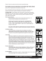
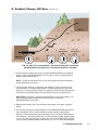
STEERABLE
UNDERGROUND
BORING
TOOL
GRUNDOSTEER
Operators & Parts Manual
®
TT TECHNOLOGIES, Inc.
Table of Contents
Safety Section
Safety Information about the GRUNDOSTEER . . . . .4-7
Operations
1.
2.
3.
General Information . . . . . . . . . . . . . . . . . . . . . . . . . . . . . .8
Applications . . . . . . . . . . . . . . . . . . . . . . . . . . . . . . . . . . . . .9
Technical Specifications . . . . . . . . . . . . . . . . . . . . . . . . . .9
Tool Length . . . . . . . . . . . . . . . . . . . . . . . . . . . . . . . . . . . . . . . . . . . .9
Tool Weight . . . . . . . . . . . . . . . . . . . . . . . . . . . . . . . . . . . . . . . . . . . .9
Tool Diameter . . . . . . . . . . . . . . . . . . . . . . . . . . . . . . . . . . . . . . . . . .9
Compressor Requirements . . . . . . . . . . . . . . . . . . . . . . . . . . . . . . . .9
Hose Length & Construction . . . . . . . . . . . . . . . . . . . . . . . . . . . . . . .9
Tool Heads . . . . . . . . . . . . . . . . . . . . . . . . . . . . . . . . . . . . . . . . . . . .9
Sonde Specifications . . . . . . . . . . . . . . . . . . . . . . . . . . . . . . . . . . . . .9
Receiver & Remote . . . . . . . . . . . . . . . . . . . . . . . . . . . . . . . . . . . . . .9
Control Unit . . . . . . . . . . . . . . . . . . . . . . . . . . . . . . . . . . . . . . . . . . . .9
Lubricator . . . . . . . . . . . . . . . . . . . . . . . . . . . . . . . . . . . . . . . . . . . . .9
4.
Set Up . . . . . . . . . . . . . . . . . . . . . . . . . . . . . . . . . . . . . . . . . .9
Launch & Exit Pits . . . . . . . . . . . . . . . . . . . . . . . . . . . . . . . . . . . . . . .9
Head Assembly
. . . . . . . . . . . . . . . . . . . . . . . . . . . . . . . . . . . . . . .10
Tool Calibration . . . . . . . . . . . . . . . . . . . . . . . . . . . . . . . . . . . . . . . .12
System Set Up . . . . . . . . . . . . . . . . . . . . . . . . . . . . . . . . . . . . . . . .12
2
TT TECHNOLOGIES, INC.
5.
Operation . . . . . . . . . . . . . . . . . . . . . . . . . . . . . . . . . . . . . . .15
Alignment . . . . . . . . . . . . . . . . . . . . . . . . . . . . . . . . . . . . . . . . . . . .15
Tracking . . . . . . . . . . . . . . . . . . . . . . . . . . . . . . . . . . . . . . . . . . . . .15
Steering . . . . . . . . . . . . . . . . . . . . . . . . . . . . . . . . . . . . . . . . . . . . .15
Soil Conditions . . . . . . . . . . . . . . . . . . . . . . . . . . . . . . . . . . . . . . . .16
Horizontal Straight Bore, No Slope . . . . . . . . . . . . . . . . . . . . . . . . .16
Right Bend 3 o'clock Bore . . . . . . . . . . . . . . . . . . . . . . . . . . . . . . . .18
Gradient Change, Hill Bore . . . . . . . . . . . . . . . . . . . . . . . . . . . . . . .19
6.
7.
8.
9.
Attachments/Accessories
Maintenance . . . . . . . . . . . .
Troubleshooting . . . . . . . . .
Replacement Parts . . . . . .
.
.
.
.
.
.
.
.
.
.
.
.
.
.
.
.
.
.
.
.
.
.
.
.
.
.
.
.
.
.
.
.
.
.
.
.
.
.
.
.
.
.
.
.
.
.
.
.
.
.
.
.
.
.
.
.
.
.
.
.
.
.
.
.
.
.
.
.
.
.
.
.
.
.
.
.
.
.
.
.
.
.
.
.
.
.
.
.
.
.
.
.
.20
.21
.21
.22
TT TECHNOLOGIES, INC.
3
Important Safety Instructions
1.
This symbol calls attention to important safety instructions which, if not
followed, could result in serious personal injury or death.
Read, understand and observe all safety information and instructions in
this manual, and on safety decals on the GRUNDOSTEER piercing
tool before using it. For safety reasons, read the operators manual
carefully and exercise caution while using the GRUNDOSTEER
piercing tool. Please note specific safety requirements as
explained by procedures called out in this manual. Failure to follow these instructions
could result in serious personal injury or death.
All tools, materials and equipment manufactured and supplied by TT Technologies, Inc.
are designed to be used by qualified and trained personnel only. TT Technologies, Inc.
will not be held liable for any injury or damage to either people or property resulting from
the misuse of TT Technologies equipment.
Please save this user's guide for future reference and have it available to all
operating personnel. Personnel should thoroughly read this operating manual.
READ MANUAL
FIRST
WEAR SAFETY
GLASSES
WEAR SAFETY
SHOES
WEAR SAFETY
GLOVES
CAUTION:
When working with compressed air, follow
necessary precautions to avoid injury.
WARNING:
Before you dig, contact the local utilities to
determine the location of all area
service lines.
DANGER:
Contact with electrical lines may result in
death or injury. The user should be properly
trained in correct procedures for work around
electrical lines.
SAVE THESE INSTRUCTIONS
4
WEAR
HARD HAT
TT TECHNOLOGIES, INC.
Follow all safety instructions concerning safety and possible danger.
Do not modify or remove the safety devices or warning labels of this machine. Keep all
labels regarding safety and possible danger on the machine in good, readable condition.
Special care is required before and during the safety check.
Every crewmember should fully understand the safety measures required for the
operation and should be capable of following these regulations individually.
GRUNDOSTEER is manufactured to the current technical safety-relevant regulations.
Nevertheless, the use of the machine may represent a danger to the health and life of
users or third parties. Always ensure that you pay particular attention to warnings,
safety labels and instructions.
Read Operators Manual
Before starting the machine, fulfill all safety related requirements. All
personnel should thoroughly read this operating manual.
Follow all safety instructions concerning safety and possible danger.
Do not modify or remove the safety devices or warning labels of this
machine. Keep all labels regarding safety and possible danger on the
machine in good, readable condition. Special care is required before and
during the safety check.
Every crew member should fully understand the safety measures required for
the operation and should be capable of following these regulations individually.
Call Before You Dig
Check the existence and exact position of buried pipe and cables by
contacting the respective utilities or owners of networks. The exact and
definite existence and position of buried cables and pipes should be defined
by trial pits or using cable and pipe detection equipment or other means.
Cable Strike
Should you accidentally hit an electrical cable, immediately leave the site,
ensure no one enters and contact the electrical company to turn off the supply.
DO NOT touch the hose couplings or the control box. Be aware of the
potential for current to be running through the hose. In case of a cablestrike,
the danger resulting from that damaged electric cable can only be evaluated
following detailed information by the respective electrical company. Never rely
on your own knowledge as to types of cables, safety measures and protective
measures that may not be correct for the type of cable encountered. Always
consider cables to be “live” and a potential danger to life. Do not re-enter the
site until authorized by the electrical company.
Danger of Entrapment
Do not place hand in moving machine components or devices. Always ensure
that all safety guards, covers or other safety devices are correctly in place
“before starting.” Do not remove safety covers or safety devices during
operation of the machine.
No loose clothes
Do not wear loose clothes or long hair. Danger of body injury by loose clothes
or hair being caught in the moving parts of the machine.
SAVE THESE INSTRUCTIONS
TT TECHNOLOGIES, INC.
5
Do Not Over-Pressurize
Do not over pressurize, otherwise explosion or serious damage may occur.
Do not exceed the operating pressure of 100 psi (7 bar). Make sure to only
use original T.T. hoses with T.T. couplings that are suitable for this pressure.
Suspended loads
Do not stand under suspended (floating) loads. Danger of body injury by
falling loads. Use suitable means of avoiding danger.
Safety Equipment
The operating crew should always wear the appropriate safety equipment, i.e.,
safety shoes/boots, hard hat, safety glasses, gloves, ear protection etc.
Safety mats should also be used to protect from electrical shock.
Operation by Qualified Personnel Only
Operation of the GRUNDOSTEER should be carried out by suitably trained,
qualified, and certified personnel only. New operators or operators in training
should be working under the constant supervision of a qualified person.
Personnel operating the GRUNDOSTEER should have sufficiently studied the
operating manual.
Disconnecting Air Hoses
Only disconnect pressure free hoses. Always turn off the compressor and
bleed all air before disconnecting hoses. Before starting any maintenance or
inspection work, ensure that the GRUNDOSTEER is not connected to any air
supply. During repair and maintenance operations always follow the
respective safety recommendations. Repair and maintenance operations are
restricted to trained and certified staff only.
Skin Burning Warning
This item can be hot or cold. Do not touch as burns may result.
Air Hose and GRUNDOSTEER Tool Maintenance
Never use self-swaged hoses. Swaging, re-fitting or replacement of air hoses
should always be done in a specialist workshop only. Make sure that the hose
couplings are properly tightened before starting the compressor. Check all
hoses, pipe lines, fittings, joints and securing bolts daily for correct position
and function before starting the bore. Use the machine only if it is in perfect
working order and after studying the operating manual, particularly the
safety-related sections. Always check the machine and its accessories for
unwanted movements.
To guarantee long life, regular maintenance is essential. Inadequate or
infrequent repair and maintenance operations may lead to accidents,
downtime and costly repairs of the machine.
Transporting the GRUNDOSTEER Tool
Danger of accidents. The downward movement of the piston may lead to the
GRUNDOSTEER slipping through the textile sling or through the operator’s
hand. Never lift or carry the machine using the air hose-damage to the hose
may result. Handling and transporting the machine should be done on a flat,
level surface only. Do not overload the transportation vehicle.
SAVE THESE INSTRUCTIONS
6
TT TECHNOLOGIES, INC.
Using a Starting Cradle & Entrance & Exit Pit Excavation
It is recommended that the GRUNDOSTEER be used with the starting cradle
for correct alignment. Do not touch the steel cable. Do not re-tension during
operation. In case of boring above or below known utilities (electrical, gas,
water, telecom or others) make sure that a starting cradle is used to align the
machine onto the target point.
Secure the starting cradle so that the front is the length of the
GRUNDOSTEER head assembly away from the front wall. The walls of the
starting pit should be made vertical where the machine enters. If the soil in
the starting pit is very soft and loose, then the cradle should be supported on
wooden boards, fixed timber or other means. Always ensure that no buried
services are beneath the starting cradle in the launch pit otherwise you may
drive an earth anchor into them and cause serious damage.
Make sure there is a sufficient amount of ground cover.
Make sure that start and exit pits are excavated and shored as necessary to
comply with OSHA regulations and guard against collapse.
Operation of the GRUNDOSTEER Tool
Start operation of the GRUNDOSTEER on reduced air (pressure) only.
Always run the GRUNDOSTEER slowly into the ground.
The control unit/lubricator, should always be within reach of the operator.
In case of danger to people or machine, turn off the air supply from the
compressor immediately. Always watch the behavior and reaction of your
colleagues. In case of danger, take the necessary steps immediately.
Use recommended oils and lubricants only.
WARNING: System under pressure!
Firmly hold or block the hose end when cleaning the hose with compressed
air. Point the hose away from body. Do not point hoses at others.
Respect a minimum safety distance from any over head live lines.
When operating beneath railroad tracks, all standards and requirements
should be observed. Machine and equipment should be removed from a job
site on the track-free side. Never cross the tracks unless supervised.
Call before you dig-Existing utilities should still be “pot-holed” for exact
location.
Turn off compressor and bleed air before disconnecting any hoses.
Operate at 100 PSI.
Torquer wrench-when a steer is completed and you release the tension switch
on the torque wrench there is often a “re-coil” effect. The wrench will spin
around. Watch face. Keep both hands on wrench.
Utility companies will generally have safety mats, & safety boots, etc.
implemented in their safety procedures.
SAVE THESE INSTRUCTIONS
TT TECHNOLOGIES, INC.
7
General Information
1.
The 3-inch diameter GRUNDOSTEER is pneumatically powered and can bore up to 200
feet. Sensors on the tool provide pitch and roll information to the operator. An above
ground locator is used to track the tool’s position and movement (see Fig. 1).
FIG. 1: GRUNDOSTEER
The operator can make adjustments to the tool’s course by rotating the air hose with a
hydraulic tensioning unit called a torquer. The tool does not require any special drilling
fluid to work properly (see Fig. 2).
Locator
Steering
Head
Yellow Wire Spring
w/Reverse Control Hose
GRUNDOSTEER Tool
Sleeve
Red
Air Hose
In-Line Lubricator
Hydraulic
Torquer
Wrench
Dataview
Remote
with on/off
Control Box
w/12 Volt
Battery
Swivel
Quick
Disconnect
Torquer Frame
Compressor
FIG. 2: TYPICAL SET UP OF THE GRUNDOSTEER
8
TT TECHNOLOGIES, INC.
Applications
• Installing up to 2-inch pipe for distances up to 200 ft.
• For shots with grade changes, multiple existing utilities to avoid, or turns and bends.
• Ideal for gas and water service lines
2.
Technical Specifications
• Tool length-87 inches
• Tool weight-85 pounds
• Tool diameter-3 inches
3.
• Compressor requirements-35 cfm @ 95-105 psi
• Hose length and construction-1 1/4 inches by 65 ft single wire reinforced, positive lock
quick disconnect couplers on both ends of the hose and tool
• Tool heads:
• 0°-Straight Boring
• 3°- Hard Soil
• 5°- Standard/Normal Soil
• 7°- Soft Soil
• Maximum bore length-200 ft.
• Sonde-DCI and RD -15 ft range, zero sleep, one AA battery (12 hour life)
• Receiver/Remote-DCI and RD - provide pitch, roll, and depth readings to operators
• DCI-3 rechargeable battery packs and re-charger
• RD-receiver takes 12 AA batteries / remote takes 2 C batteries
• Control unit-rechargeable 12 Volt battery
• Lubricator with ball valve to control air flow / oil consumption adjustment knob
Set Up
A. Launch & Exit Pits
Launch pits should be approximately 7 feet long and a minimum of 30 inches deep.
Each job site is different and should be evaluated accordingly. The GRUNDOSTEER
can also be surface launched.
4.
TT TECHNOLOGIES, INC.
9
B. Head Assembly
1. Install 1 AA battery, positive side down, in sonde (see Fig. 3). Screw cap on
tightly.
2. Attach sonde to adapter making sure 12 on sonde line up with 12 on adapter
(see Fig. 4).
FIG. 3: INSTALL 1 AA BATTERY
FIG. 4: ATTACH SONDE
3. Slide sonde and adapter into front of GRUNDOSTEER tool (see Fig. 5); align
holes for roll pins (see Fig. 6).
10
FIG. 5: SLIDE ON SONDE ADAPTER
FIG. 6: ALIGN HOLES
FIG. 7: INSTALL OUTER ROLL PIN
FIG. 8: INSTALL INNER ROLL PIN
TT TECHNOLOGIES, INC.
4. Install outer roll pin beveled edge down (see Fig. 7).
NOTE: Single solid steel pin also available for GRUNDOSTEER head assembly.
5. Install inner roll pin beveled edge down (be sure to stagger slits in outer and inner
roll pins) (see Fig. 8).
6. Slide sleeve onto tool beveled edge first (this is the only way it will go on)
(see Fig. 9). Check to see that sleeve will rotate freely. If not, take off and adjust
roll pins with pin punch (one side is probably sticking out too far). When sure
sleeve will rotate freely, take off sleeve and clean thoroughly. Slide sleeve back
onto tool.
7. Slide on tapered head (see Fig. 10). It will only go on one way. The 12 o’clock
on the head will align with the 12 on the sonde and sonde adapter.
FIG. 9: SLIDE ON SLEEVE
FIG. 10: SLIDE ON TAPERED HEAD
8. Install outer roll pin beveled edge down (see Fig. 11).
9. Install inner roll pin beveled edge down (be sure to stagger slits in outer and inner
roll pins) (see Fig. 12).
FIG. 11: INSTALL OUTER ROLL PIN
FIG. 12: INSTALL INNER ROLL PIN
TT TECHNOLOGIES, INC.
11
C. Tool Calibration
1. Lay tool on flat surface away from any overhead interference such as telephone
lines.
2. Consult DCI or RD owner’s manual for calibration instructions.
D. System Set Up
Locator
Steering
Head
Yellow Wire Spring
w/Reverse Control Hose
GRUNDOSTEER Tool
Sleeve
Red
Air Hose
In-Line Lubricator
Hydraulic
Torquer
Wrench
Dataview
Remote
with on/off
Control Box
w/12 Volt
Battery
Swivel
Quick
Disconnect
Torquer Frame
Compressor
FIG. 13: TYPICAL SET UP OF THE GRUNDOSTEER
1. IN-LINE LUBRICATOR
Attach compressor hose (not supplied by TT) to ball valve side of lubricator
(claw fitting) and secure with safety clip. Fill lubricator with Grundo-oil and set
oil adjustment knob to the 3 setting. Set the lubricator next to the entry pit.
2. RED AIR HOSE
Run the supplied red air hose, 50 ft, from other end of lubricator directly behind
entry pit or off to the side if obstacles are present behind the entry pit. Attach at
lubricator using safety clip.
3. CONTROL BOX
Attach open end of red air hose using
safety clip. Be sure emergency off
switch is not pressed down which can
happen during transport. Be sure
battery terminals are connected and
secure. Attach GRUNDOSTEER
yellow hose female end to control
box and run back towards entry pit
(see Fig. 14).
NOTE: As the GRUNDOSTEER
bores the control box will slide along
with the hose toward the entry pit.
FIG. 14: ATTACH TO CONTROL BOX
12
TT TECHNOLOGIES, INC.
4. TORQUER FRAME
Torquer frame should be set up at surface level directly in back of starting pit in
line with the direction of the bore. Loosen the down screws at the bottom of the
frame to adjust the frame’s legs. Tighten before staking frame.
Use 2-ft anchor stakes provided to secure the frame (see Fig. 15). When
working on concrete or surfaces where the frame cannot be staked down, use
sandbags to secure the frame. Attach frame accessories remote holder, cup
holder, and DCI or RD display unit holder.
FIG. 15: STAKE FRAME
FIG. 16: YELLOW AIR HOSE
5. YELLOW AIR HOSE
Attach only one length at a time to limit set up space needed. Be sure hose is
laid out flat with no kinks. Feed open end of GRUNDOSTEER hose through the
torque frame (see Fig. 16).
NOTE: Make sure the airline (hose) is free of obstructions before using. Make
sure that all airlines are in good working order and condition before use.
6. HYDRAULIC TORQUER WRENCH
Remove clip and pin from top of wrench and remove top portion (see Fig. 17).
Slide bottom portion of wrench around the yellow GRUNDOSTEER hose
between the arms of the torque frame. Attach top part of wrench with pin
and clip (see Fig. 18).
FIG. 17: SLIDE BOTTOM ON
FIG. 18: CLIP TOP ON WITH PIN
To tension torquer around hose, engage hydraulic cylinder by pushing lever
forward. This will allow the torquer to tension around the hose as the handle is
pumped. To release pressure, disengage lever.
TT TECHNOLOGIES, INC.
13
7. REMOTE
Secure remote in its holder and run cable back to the control unit. Connect the
cable to the control unit making sure that the numbers of the prongs on remote
and control unit line up.
IMPORTANT: Before attaching tool, open valve at lubricator, take off safety cap
on male end of hose, start compressor, turn the remote on to start airflow. This
will clean out the airline and prevent dirt and other impurities from entering the
tool.
WARNING: System under pressure! Hold on to hose tightly, point away from
face, make sure others are out of the way, wear eye protection. Shut
compressor off before attaching hose to tool.
8. TOOL
Attach male end of yellow GRUNDOSTEER hose that has been fed through
torque frame to the tool (see Fig. 19). There is a positive lock on the fittings for
this connection. If 3 teeth are not aligned with 3 slits on the hose fitting, the
connection will bottom out 2/3 of the way. Adjust and tighten completely.
FIG. 19: ATTACH TO TOOL
FIG. 20: ATTACH TO CONTROL BOX
CAUTION: Do not over tighten. Do not use wrenches.
Lay the GRUNDOSTEER in the bottom of the entry pit and turn on compressor.
Make sure it is operating correctly by switching from forward to reverse and fast
to slow.
Place DCI or RD receiver at front of starting pit. Turn on the DCI or RD remote
display at the torque frame. Both receiver and remote display should read the
same information clock position.
EXAMPLE: If the 12 on the tapered head is up it should read 12 on the receiver
and remote display. Roll tool in both directions to make sure clock position
changes on receiver and remote display.
14
TT TECHNOLOGIES, INC.
Operation
A. Alignment
On a straight shot the GRUNDOSCOPE and surveyors stake are handy accessories.
Otherwise perfect alignment is not required because of the tool’s steering capability.
B. Tracking
One person is needed to monitor the progress of the tool with the DCI or RD receiver.
Mark the exact path of the tool with flags, paint, etc, every 10 feet. Marking the path
displays how the GRUNDOSTEER has moved toward the target and helps prevent
oversteering.
5.
NOTE: Please consult locator user manual for tracking information and proper locator
operational instructions.
C. Steering
One person needs to steer the tool. This person will receive the same information
as the tracker and can adjust the tool as needed.
Planning ahead is essential to successful
steering. Each shot should be mapped out
prior to operation.
Steering is accomplished by rotating the air
hose, with the hydraulic tensioning unit,
(torquer) in order to rotate the tool head to
the required position (see Fig. 21). Once
the tool head is in the proper position, it will
guide the tool in the chosen direction until a
new direction is chosen.
NOTE: Depending on soil conditions, it
takes on average 7 ft. to get the tool to
react/change direction.
FIG. 21: STEERING TOOL
EXAMPLE: A straight shot, running at 5% positive pitch and at a depth of 40 inches, in
the 12 o’clock position. Turn the GRUNDOSTEER hose until the tool reaches the 6
o’clock position in order to level out. The tool continues to lose depth over the next 7 ft.
because it is moving toward leveling out and eventually steering downward to give a
negative pitch. So, 10 ft. after the initial change to 6 o’clock the reading might be 0%
pitch at 36 inches of depth.
TT TECHNOLOGIES, INC.
15
D. Soil Conditions
The GRUNDOSTEER will operate in the same soil conditions as a standard piercing
tool. For extreme rocky conditions TT Technologies recommends using the
GRUNDOMAT piercing tool.
NOTE: Using the starting cradle is recommended in order to help keep the
GRUNDOSTEER level. Run the tool on the slow speed and always start in the
6 o’clock position to keep tool from rising.
NOTE: If ground conditions are extremely soft the tool will move too fast and not “bite”,
steer, nor move. This is indicated by noticeable hose shaking.
NOTE: If slow speed on remote is not slow enough, cut air back at lubricator. If the air
is cut back as far as possible, but the tool is not moving, push on GRUNDOSTEER
hose.
IMPORTANT: It is possible to steer the tool while it is moving. Beware of oversteering.
E. Horizontal Straight Bore, No Slope,
for use with tapered tool head (see Fig. 22)
BORE PATH
EXIT PIT
ENTRY PIT
0% grade
-2, -3% grade
+2, +3% grade
-2, -3% grade
12
12
12
12
9
3
9
6
3
6
9
3
6
9
3
6
FIG. 22: The tool goes through a series of subtle pitch and depth adjustments, equaling zero, to
achieve a straight bore. Start at 6 o'clock 0% grade, when you reach -2, -3% grade steer the tool to
the 12 o'clock position. Once you reach +2, +3% grade, steer back to the 6 o'clock position.
1. Place GRUNDOSTEER in the 6 o’clock position on the starting cradle. If the
GRUNDOSTEER is launched at the installation depth, the Dataview should read
0%. Position the tool with the assistance of a GRUNDOSCOPE aiming frame
and surveyors stake.
NOTE: Please consult locator user manual for tracking information and proper
locator operational instructions.
2. Switch the compressor on and let the tool enter the soil slowly in the 6 o’clock
position. Run the GRUNDOSTEER until the reverse cone has reached the soil.
16
TT TECHNOLOGIES, INC.
IMPORTANT: Always launch the GRUNDOSTEER in the 6 o’clock position to
prevent the tool from surfacing prematurely.
NOTE: A standard, non-tapered, tool head is available for straight horizontal
boring with the GRUNDOSTEER. Do not follow this procedure for that tool head.
3. Remove the starting cradle. Do not tension the torquer at this point.
4. Bring the tool up to speed and continue boring in the 6 o’clock position,
monitoring the tool’s progress with the locator. Continue boring until the
indicator reads -2% to -3%.
5. Tension the torquer around the special yellow compressed air hose.
6. Pre-tension the hose before putting the GRUNDOSTEER in reverse. Begin to
turn the torquer toward the 12 o’clock position.
7. Reverse the GRUNDOSTEER, backing the tool up approximately 1-foot or more.
Maintain tension and pay close attention to the data view.
8. Switch the GRUNDOSTEER back to forward with the remote control, maintaining
tension toward the 12 o’clock position. Monitor the tool’s position closely with the
data view.
9. If the tool does not reach the desired 12 o’clock position after traveling forward
1-foot, repeat steps 7 and 8 until the 12 o’clock position is achieved.
10. Continue boring in the 12 o’clock position until the indicator reads +2% to +3%.
At this point, turn the GRUNDOSTEER to the 6 o’clock position by using the
same reverse/forward method described in steps 7 and 8.
11. Repeat steps 4 through 10 until the bore is complete.
TT TECHNOLOGIES, INC.
17
F. Right Bend 3 o’clock Bore
(see Fig. 23).
12
9
3
6
BORE PATH
EXIT PIT
12
9
3
6
ENTRY PIT
FIG. 23: Start at 6 o'clock position, then steer to 3 o'clock to make right bend.
Typical bend radius = 85 feet.
1. Place GRUNDOSTEER in the 6 o’clock position on the starting cradle. If the
GRUNDOSTEER is launched at the installation depth, the Dataview should
read 0%.
NOTE: Please consult locator user manual for tracking information and proper
locator operational instructions.
2. Switch the compressor on and let the tool enter the soil slowly in the 6 o’clock
position. Run the GRUNDOSTEER until the reverse cone has reached the soil.
3. Remove the starting cradle. Do not tension the torquer at this point.
4. Continue boring until the GRUNDOSTEER is in the ground approximately 3 feet.
5. Pre-tension the hose before putting the GRUNDOSTEER in reverse. Begin to
turn the torquer toward the 3 o’clock position.
6. Reverse the GRUNDOSTEER, backing the tool up approximately 1-foot.
Maintain tension and pay close attention to the data view.
7. Switch the GRUNDOSTEER back to forward with the remote control maintaining
tension toward the 3 o’clock position. Monitor the tool’s position closely with the
Dataview. Loosen the torquer and remove tension from the hose.
8. Monitor the progress of the GRUNDOSTEER closely. If the tool slips into the 1
o’clock or 5 o’clock positions, repeat steps 5 through 7 in order to restore its
proper coarse.
9. To change direction, repeat steps 5 through 7, turning the GRUNDOSTEER to
the chosen direction.
18
TT TECHNOLOGIES, INC.
G. Gradient Change, Hill Bore
(see Fig. 24).
EXIT PIT
BORE PATH
DESIRED
GRADE
12
-2%, -3%
under desired
grade
+2%, +3%
over desired
grade
12
12
12
ENTRY PIT
9
3
6
9
3
6
9
3
9
6
3
6
FIG. 24: Start at 12 o'clock position. Once the desired grade is achieved,
alternate between 6 o'clock and 12 o'clock until the bore is complete.
1. Find the pitch or grade of the hill by laying the GRUNDOSTEER on the slope of
the hill. While the GRUNDOSTEER is on the slope, use the tracking device to
determine the grade of the hill.
NOTE: Please consult locator user manual for tracking information and proper
locator operational instructions.
2. If the bore takes place on a negative grade (downhill), launch the tool in the 6
o’clock position. If the bore takes place on a positive grade (uphill), launch the
tool in the 12 o’clock position. Switch the compressor on and let the tool enter the
soil slowly in the desired position until the reverse cone has reached the soil.
IMPORTANT: Boring on a continuous downhill slope is not recommended. The
inflow of ground water through the back of the tool can cause the
GRUNDOSTEER to shut down.
3. Remove the starting cradle. Do not tension the torquer at this point. Continue
boring.
4. Once the tool achieves the desired grade, run the GRUNDOSTEER between the
6 o’clock position and 12 o’clock position to maintain grade as described in
Section E. Alternate between the two positions every 7 to 10 feet, depending on
soil conditions. Continue boring in the 12 o’clock position until the indicator reads
+2% to +3% over desired grade. At this point, turn the GRUNDOSTEER to the 6
o’clock position and bore until the indicator read -2% to -3% under desired grade.
TT TECHNOLOGIES, INC.
19
Attachments & Accessories
Lubricators & Accessories
Part Number
GRU 2002291
GRU 2002520
6.
GRU 2002300
Starting Cradle & Accessories
Part Number
GRU 0750011
GRU 2000030
G-E 0751000
G-E 0751002
G-E 0751110
GRU 2000130
GRU 2000180
Description
Starting Cradle (with non-return roller), and
Ground Stakes
Ground Stakes for Starting Cradle
Grundoscope 3'-5', with Aiming Frame and
5' Surveyor's Staff
Grundoscope 5'-6.6', with Aiming Frame and
6.6' Surveyor's Staff
5' Surveyor's Staff
6.6' Surveyor's Staff
9.8' Surveyor's Staff
GRU
GRU
GRU
GRU
GRU
GRU
GRU
GRU
GRU
GRU
2002060
2002308
2002311
2002317
2002312
2002313
2002309
2002314
2002318
2002315
GRU 2002316
GRU 2004110
GRU 2004120
Description
Lubricator, 1 gallon with Stopcock, w/o Hose
6.6' Connection Air Hose DN 25 with
Mody Couplings
3.3' Connection Air Hose DN 25 with
Mody Couplings
Locking Coupling for Mody Couplings
.3 Gallons GRUNDO-OIL
1.3 Gallons GRUNDO-OIL
6.6 Gallons GRUNDO-OIL
13.2 Gallons GRUNDO-OIL (2-6.6 gal. cans)
52.8 Gallons GRUNDO-OIL (8-6.6 gal. cans)
.3 Gallons GRUNDO-OIL Extra
1.3 Gallons GRUNDO-OIL Extra
6.6 Gallons GRUNDO-OIL Extra
13.2 Gallons GRUNDO-OIL Extra
(2-6.6 gallon cans)
52.8 Gallons GRUNDO-OIL Extra
(8-6.6 gallon cans)
1" x 32.8' Special Rolled Hose with Claw
Couplings
1" x 65.6' Special Rolled Hose with Claw
Couplings
Torquer, Frame & Air Hose Accessories
Part Number
G-L 0752255
G-L 0752255A
G-L 0753400
YY 051920
YY 051941
G-L 0752300A
G-L 0752320
Description
65.6' Compressed Air Hose with internal
control hose and torsion-proof round thread
couplings
32.8' Compressed Air Hose with internal
control hose and torsion-proof round thread
couplings
Manual Tensioning System (Torquer) with
Bearing Frame
Manual Tensioning System (Torquer) without
Bearing Frame
Bearing Frame
Control Unit with Electric-Activated Magnet
Valves
Cable Remote Control with Foot-Switch and
82' Cable for Controlling Unit
Pipe Pullers & Accessories
Part Number
G-L SN2535A
G-L SN2535B
G-L SN3545A
G-L SN3545B
G-L SA2410A
G-L SB2410A
G-L SA2420A
G-L SB2420A
YY 051968
YY 051969
DigiTrak & Radio Detection Locating
Accessories
Part Number
SEN 0705
98SDRR3
98CDCC
98CDBC
98CDBP
SEN 0205
98CDMAN
98CDDC
SEN 0700
9913036
9943007
SEN 0200
9913038
20
Description
DigiTrak Mark III System with Special
Transmitter (without Dataview)
Receiver DRR3
System Case DCC
Battery Charging Unit DBC (115 V & 230 V)
Battery Pack DBP
Transmitter DS Short-Range without
Sleep-Mode
DigiTrak Manual
Remote Transmission Monitor
(Dataview) DDC3
Radio Detection System with Special Slim
Sonde (without Dataview)
Receiver RD 385
Bag for RD 385 Location System
Slim Sonde without Sleep-Mode
Remote Transmission Monitor (Dataview)
TT TECHNOLOGIES, INC.
Description
Pipe Puller 25-35 with Socket
Pipe Puller 25-35 with Plug
Pipe Puller 35-45 with Socket
Pipe Puller 35-45 with Plug
Pipe Puller DN 50 with Socket PE 80
PN4(SDR26)-PN10(SDR11)
Pipe Puller DN 50 with Plug PE 80
PN4(SDR26)-PN10(SDR11)
Pipe Puller DN 63 with Socket PE 80
PN4(SDR26)-PN10(SDR11)
Pipe Puller DN 50 with Plug PE 80
PN4(SDR26)-PN10(SDR11)
Cable Connection Nipple with Hose
Coupling Socket
Cable Connection Nipple with Hose
Coupling Plug
GRUNDEX Mud-and-Water Pump &
Accessories
Part Number
GRU 2001032
GRU 2001033
GRU 2001036
Description
GRUNDEX II Mud & Water Pump, without
Connection Hose
9.8' GRUNDEX Connection Hose with
C-hose Coupling
16.4' GRUNDEX Connection Hose with
C-hose Coupling
Maintenance Tools & Accessories
Part Number
GRU 2003290
GRU 0753300
GRU 2003291
G-L 0753500
GRU 0753540
GRU 0753541
G-E 0753550
GRU 2003530
Description
Assembly Table for GRUNDOSTEER
GRUNDOCLAMP 75 (Assembly Clamp)
Assembly Table (Lightweight) with Simple
Clamping Device
Tool Box
C-Spanner D76 (set=2 pieces)
C-Spanner D76 (1 piece)
Open-Jawed Spanner
Piston Extractor
Maintenance
The tool should be flushed with air tool oil after each usage, and again before any
period of extended storage. This helps prevent premature failure of the teflon seals.
Seals should be inspected and replaced as needed after every 400 work hours or one
year of usage.
• Charge battery in control unit overnight after each use
• Flush tool with Grundo-oil lubricant and diesel fuel mixture after each bore
• Keep out dirt and elements by always using provided end caps for tool, hoses,
lubricator, control unit and remote.
• Take head assembly apart daily, must be done for sonde battery purposes anyway.
Clean all dirt before reassembling for next shot.
7.
Troubleshooting
PROBLEM: Tapered head, barrel of tool and hose will not rotate freely inside of
oversized sleeve.
SOLUTIONS:
• Roll pins not installed correctly.
• Dirt build-up in sleeve. Clean sleeve.
8.
PROBLEM: You have been steering at 3 o’clock but the tool is turning in the 9
o’clock direction.
SOLUTIONS:
• Sonde has been improperly installed, check to make sure 12’s line up.
PROBLEM: Tool will not start.
SOLUTIONS:
• Emergency off switch has been pressed on control unit.
• Check all hose connections.
• Control unit 12 V battery is dead.
TT TECHNOLOGIES, INC.
21
Replacement Parts List
9.
22
TT TECHNOLOGIES, INC.
GRUNDOSTEER- 75 PS
Ref.
Qty
Description
Part Number
5
1
Steering Head
YY 051908
5
1
Steering Head, Straight
YY 052009
10
1
Roll Pin Kit
RZ 2201102
15
1
Steering Head Adapter
YY 051910
16
1
O-Ring, 40x 2.5 mm
21252496
20
1
Head Adapter Pin
YY 052011
25
1
Rotation Sleeve
YY 051914
30
1
Sonde Sleeve (Inner Tube for Transmitter)
YY 051809
35
1
Casing
YY 051810
40
1
Piston
G-P 0755141
45
1
Piston Slide Tapes (set)*
G-P 0755130
50
1
Piston Seal*
G-P 0755160
55
1
Control Stud Housing
G-Z 0756460
60
1
Control Stud (Complete, with Connection Hose)
G-L 0758004
65
1
Control Seal
70
1
Control Sleeve Seal (set)*
80
1
Inner Tube
85
1
O-Ring 24/33x7
21025005
90
1
Reverse Sleeve
YY 050930
95
1
Outer Tube
YY 050932
100
1
O-Ring, 30x2.5 mm
21251967
105
1
Spring
YY 050934
110
1
Elastic Block
115
1
Reverse Cone
G-L 0756450
120
1
Roll Pin Kit
G-L 0756452
125
1
Whip Hose (Complete, NW 32)
G-L 0752200
130
1
Reversing Manifold
YY 050933
135
1
O-Ring, 26x3 mm
21251753
140
1
Lock Piece
YY 052006
145
1
Structural Spring for Whip Hose NW 32
YY 051882
150
2
Hose Crimp, 55x2.5x60
G-L 0752360
155
5
Structural Band, 53x1.5x30
G-L 0752363
160
2
Shift Hose Crimps, 12x1x40
YY 060969
165
1
Control Hose (Internal) 0.37 m, without Couplings
G-L 0752205
170
1
Air Hose, without Couplings DN32, 300 feet long
G-L 0752210
175
1
Threaded Sleeve for connection to Air Hose DN 32
180
1
O-Ring, 33x4 mm
21252128
185
1
Hose Nipple with Socket
YY 051869
190
1
Air Fitting
195
1
Snap Ring, 12x1 mm DIN 471
200
1
O-Ring, 6.5x2 mm
21250387
205
1
Hose Cap for DN 32
YY 060988
5-205
1
GRUNDOSTEER 75 PS with Connection Air Hose (w/o Transmitter)
G-L 0750000
Complete Seal Kit
G-L 0756320
YY 191636
G-L 0758075
YY 050931
YY 051991
YY 060978
YY 060981
180471010012
TT TECHNOLOGIES, INC.
23
®
TT TECHNOLOGIES, Inc.
2020 East New York Street • Aurora, IL 60504
1-630-851-8200 • 1-800-533-2078 • FAX 1-630-851-8299
Internet http://www.tttechnologies.com
Printed in USA
TTTGSTEERUG 10/00
© Copyright 2000 TT TECHNOLOGIES, Inc.