1
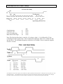
Nexus LED Driver and Interface Module.
Pulse Counter Interface.
Machines
User Manual Ver 1.0
_________________________________________________________________
BIF-PL
System Description
General
BIF-PL is an interface and control PCB that accepts either a TTL pulse train (at up to 5Khz
burst, 2.5Khz sustained) or a relay / switch contact low speed input and counts and displays the
totaliser count. The unit is designed to interface primarily to the B57 and B100 style of
integrated LED displays with driver. Up to 3 master and 3 slave LED display boards (total 12
seven segment displays) can be controlled from one BIF-PL interface. The LED driver protocol is
that of a synchronous serial bus with the data clocked on the rising edge. The interface uses
chip enable, data and clock to communicate with the MM5450 display driver IC. Other third
party displays can be linked to the unit providing they adhere to the synchronous protocol.
The board has a signal input pin that is used for both high speed and low speed count input. The
mode is selected by setting an on board jumper to either relay or TTL input. The relay features a
debounced input with timed minimum closure period. Maximum frequency is 25Hz. It is
designed for relay contact or switch style of input. The TTL signal can accept a 5Khz input
signal (TTL levels square wave ) for a short burst or 2.5Khz sustained and is designed to
interface to high speed outputs such as shaft rotation variable reluctance or opto coupled
interrupter modules.
A reset input is provided which is pulled to a high level by an on board pullup. Taking this input
to ground for a minimum reset period results in the count being cleared to 0. The count will
remain at 0 as long as the reset pin is held low. The reset pin can be taken to ground at any time
during the counting process providing the chip enable input is disabled before resetting. Resetting
with the count running may, under certain circumstances, cause the unit to lock up.
The count input (clock) has a count enable pin associated with it that can be used to strobe the
count on or off. If the enable is taken inactive then the count will cease. Taking the enable high
restarts the count.
Another feature of this board is the up/down pin that allows the count to go either in a positive
direction 0 to 999999999999 or from 999999999999 to 0 in the negative direction. This input
can be switched on the fly making the unit useful in totalising a difference value.
A single +12 volt supply is required to power the LED displays which are connected to the LED
driver outputs. All signal levels are TTL compatible logic levels. The current consumption
depends on the number of displays connected but should not exceed 2 amps.
Nexus Machines Ltd reserves the right to alter or withdraw the product specification and characteristics without prior notice at any time in line with
product development. Nexus Machines Ltd sole and exclusive warranty is that stated in the warranty article of the conditions of sale. Although every
effort is made to ensure this data is accurate no liability is accepted for errors or ommisions that may affect the end product.
Digit address and data byte organisation
The unit can drive up to 3 master boards and three slave boards making a total of 12 seven
segment displays. Digit 0 is the right hand digit, digit 11 is the left hand digit (assuming a 12 digit
display). The count input port is connected to the 6 way 0.1 inch pitch connector on the right
hand end of the interface board. Connections are as follows
Pin Number
Function
1
2
3
4
5
6
0 volts signal
Count enable (1=enable)
+5 volts for external pull ups (4k7 source resistance)
Reset input (active low with internal pullup)
Count Input (rising edge clock)
Up/Down
(1=up 0=down)
Table 1
Relay/high speed input select jumper is up for relay and down for TTL pulse.Note if relay is
selected and a high speed count applied the display will "freeze" and incorrect counting will
occur.
Nexus Machines Ltd reserves the right to alter or withdraw the product specification and characteristics without prior notice at any time in line with
product development. Nexus Machines Ltd sole and exclusive warranty is that stated in the warranty article of the conditions of sale. Although every
effort is made to ensure this data is accurate no liability is accepted for errors or ommisions that may affect the end product.
Power Connections
The power is applied to the board through a two way 0.1 inch pitch header. Polarity is marked
and a diode protects the interface from reverse polarity. IT DOES NOT PROTECT THE LED
DISPLAY/DRIVER - The B100/B57 displays and other third party displays may be damaged by
reverse connection or by "hot insertion" therefore it is advisable to check the supply polarity
before connection. The interface has its own +5 volt regulator on board to provide the required
internal +5 volt line. External LED displays should not draw more than 0.75 amps from each
LED headers +12 volt line. The user must ensure the supply voltage falls within that laid out in
the data sheet specifications otherwise damage and/or malfunction can occur. It is advisable to
provide reservoir capacitance for the displays especially if the power supply is located remotely
from the LED's. The B57 and B100 displays have on board reservoir capacitors. If a third party
display is being driven then a reservoir capacitance of 47uf per digit should be provided local to
the LED display.
Note that if 12 digits are being driven by the BIF interface then the power supply will be required
to source up to 2.0 amps (assuming all LED's on and 20mA per segment). Ensure that the cables
are of adequate cross section for the current, and are connected to the power supply in a star
point ground configuration to minimise problems with transient or loop currents. Note it is often
power supply cables which can be a source of EM interference due to the large current spikes
when the LED's change state. Good grounding and decoupling are essential.
Nexus Machines Ltd reserves the right to alter or withdraw the product specification and characteristics without prior notice at any time in line with
product development. Nexus Machines Ltd sole and exclusive warranty is that stated in the warranty article of the conditions of sale. Although every
effort is made to ensure this data is accurate no liability is accepted for errors or ommisions that may affect the end product.
LED Display/Driver Interface Connections
Three 5 pin 0.1 inch pitch connectors provide the interface to the B100/B57 displays. Note that
although usually connected to these displays this interface board will drive a third party display
providing the MM5450 driver chip is used on the board. The pin out is as follows:
Connector 1 - Right hand connector is for digit adresses 0 to 3
Connector 2 - Middle connector is for digit addresses 8 to 11
Connector 3 - Left hand connector is for digit addresses 4 to 7
All connectors have the same pin out:
Pin Number
Function
1
2
3
4
5
Chip enable (active low)
Data
Clock (rising edge active)
0 volts
+12 volt (nominal) from power header
Note the clock line, data line and chip enable line all have series resistors of 330 ohms value.
This is to provide a degree of protection against ESD discharge and accidental shorting of active
outputs. To be compatible with the B57L and B100L displays and to limit EMC radiation from
long lines the data rate has been kept around 10 k bits/sec. The timing of the clock provides a
50us high pulse duration during data valid shift out. This, combined with the software decoding
and driving, limits the update rate of the displays to 1 digit every 25ms or about 40 digit
alterations per second for the standard decode mode. This results in the count display slowing
up during high speed counting as the update rate falls and the interrupt rate rises. The unit will
not lose any counts (provided the waveform is of a suitable frequency and duty cycle) but the
displayed digits can only been seen altering in the higher digit values.
Nexus Machines Ltd reserves the right to alter or withdraw the product specification and characteristics without prior notice at any time in line with
product development. Nexus Machines Ltd sole and exclusive warranty is that stated in the warranty article of the conditions of sale. Although every
effort is made to ensure this data is accurate no liability is accepted for errors or ommisions that may affect the end product.
Count Input and LED Output Timings
Clock high time
Clock low time
CE to clk rising edge
Data stable before edge
t1
t2
t3
t4
Min
50 us
50 us
10 us
10 us
Note: The first bit of the data is a start bit. It is always a logic 1. It is followed by 32 bits
containing the LED segment data, 2 bits of annunciator data and a final clock to latch the data
into the driver. The maximum frequency of the driver is 500 KHz. Please contact the supplier
for faster versions.
Nexus Machines Ltd reserves the right to alter or withdraw the product specification and characteristics without prior notice at any time in line with
product development. Nexus Machines Ltd sole and exclusive warranty is that stated in the warranty article of the conditions of sale. Although
every effort is made to ensure this data is accurate no liability is accepted for errors or ommisions that may affect the end product.
Power on Initialisation, Reset and Count Modes
On power up the device will initialise the digit counters to 000000000000. Since power up takes
a short time (approx 100ms) any counts applied at this time will not be reliably counted. Ensure
the count enable is low and that counts are not applied during this period. Once the digits are
initialised the device is ready to count.
During counting it is possible to change from up count mode to down count mode on the fly.
This should be done by taking the count enable low whilst changing the count direction. The
count direction change should take place whilst the clock is low and be completed before the
clock and the clock enable are active. This will ensure no counts are lost. Be aware that if a
count is already in the buffer when the count direction is reversed the count will move 1 count in
the direction it was previously.
Count reversal can occur during count enable active but if this is done by a switch, the bounce
will make the count direction unpredictable if the above method is not used. For applications
requiring only one direction counting the pin can be tied to the appropriate logic level through a
2k2 resistor.
A reset during counting should be done with the count low and the count enable inactive low.
The reset must be held for the minimum period as it is scanned after the count updates and the
time for it to be serviced varies. A short pulse may not be detected as it is not latched.
It is recommended that in applications using the slow count modes or where electrical noise is
high then the inputs are filtered with 1k /0.1uf RC filters. Switches - especially cheap ones bounce and this combination will help. The length of the wires connecting the switches should
not be greater than 10 inches unless provision is made to drive them from a low impedance
source and filtering is provided close to the board inputs. Note all signal inputs are diode clamp
and series resistor protected.
Nexus Machines Ltd reserves the right to alter or withdraw the product specification and characteristics without prior notice at any time in line with
product development. Nexus Machines Ltd sole and exclusive warranty is that stated in the warranty article of the conditions of sale. Although every
effort is made to ensure this data is accurate no liability is accepted for errors or ommisions that may affect the end product.
Electrical Specification
Parameter
Supply voltage
8
Supply Current
Driven LED supply current
Min
12
Max
0
2.4
Input resistance
Input range
High speed clock
Clock duty cycle
-0.3
0
45
30
0.75
Units
VDC (1)
mA
(2)
A
(3)
0.8
vcc
V
V
5.3
5
55
K ohms
volts
KHz
%
14
18
Pulse count interface:
Logic 0 (IL=2ma)
Logic 1 (IL=2ma)
1.0
Signal rise time
Signal fall time
Low speed clock
Debounce lockout
Reset hold time
Typ
2.5
100
ns
100
ns
0
100
25
20
250
500
Hz
ms
ms
Pullup series resistance
4.7
kohms
LED display interface:
Series resistance
300
Ohms
Logic 1
Logic 0
2.4
5.25
0.8
V
V
Note 1 Although the BIF -PL unit will function down to 8 volts the B57 and B100 displays will
only remain illuminated at full output down to 11.5 volts.
Note 2 BIF board only.
Note 3 Peak current. Keep below 0.5 amps for normal continous use.
Data prepared by :
Nexus Machines Ltd
White Swan House
60 High Street
Godstone
Surrey
RH9 8LW
Tel :
Fax:
Email :
Web site :
01883 744455
01883 744466
[email protected]
www.nexus-machines.demon.co.uk