1
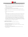
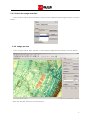
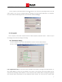
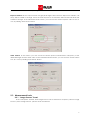
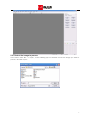
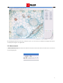
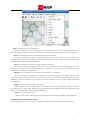
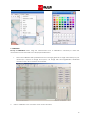
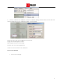
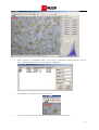
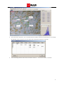
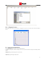
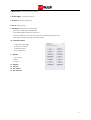
GT-Vision
GXCAM User’s Manual
N America HQ:
10205 Easterday Court
Hagerstown
MD 21742
USA
Tel: +1 240 235 4118
Fax: +1 240 235 4120
e-mail: [email protected]
Web: www.gt-vision.com
www.gxmicroscopes.com
European HQ:
GT Vision Ltd.
Hazel Stub Depot
Camps Road
Haverhill
Suffolk
CB9 9AF
UK
Tel: +44 (0)1440 714737
Fax: +44 (0)1440 709421
e-mail: [email protected]
Web:
www.gt-vision.com
www.gxoptical.com
www.gxmicroscopes.com
Chapter 1 Recommended Configuration
1.1
Operating System
GXCapture can be run under Windows XP and Windows 2000 operating systems with the component
Directshow 9.0 installed.
1.2
Hardware requirements
1.2.1 It is recommended to use a highly configured computer for the camera. The
minimum requirements are:
CPU: Intel Pentium 4 2.6GHz
Memory: 512MB
Hard drive: 1GB
USB: USB2.0 port (If a built-in USB2.0 port is not available a USB2.0 adaptor is also acceptable)
1.2.2 USB2.0 Port requirement
Before plugging in the GXCAM camera, do check that the driver of USB2.0 port on your computer
is properly installed and ready for use.
Chapter 2 Operation
2.1 Prepare for the use of GXCAM (Quick Start Guide)
Installation Procedure
Installing your GXCAM camera and associated software programs should only take a few minutes.
Please follow the steps below:
•
Install the driver for camera
Installing your GXCAM camera and associated software programs should only take a few minutes.
Please follow the steps below:
1.
Before you attach the camera always follow these basic rules when handling your camera.
When you unscrew the camera cover or when you attach a camera adapter to the camera
or when you are generally manipulating the camera ALWAYS hold the face of the camera (ie
the hole with the chip inside) pointing vertically downwards, no matter how uncomfortable or
awkward it may feel. If you do not do this, tiny particles of dust or swarf from threaded fittings
will definitely land on the chip surface and, especially in microscopes, these will be
permanently visible in your images. They can be extremely difficult to remove. We
recommend that you become obsessive about the cleanliness of your camera, it certainly
pays off! Always place a cap on the camera when not in use and unattached.
2.
Insert the disk with the GXCAM camera driver and GXCapture software.
3.
Attach the camera to your microscope, telescope or lens using the appropriate adapter.
4.
Connect the camera to a convenient USB2 port.
1
5.
Windows should automatically detect the camera when plug in one of the USB ports. In the
driver installation window, allow the drivers to be installed automatically and click ‘Next’.
6.
Ignore the warning message and ‘continue anyway’. When the installation is completed, click
‘Finish’.
7.
In case the Windows system cannot detect the camera automatically, open the ‘Device
manager’ from the Windows ‘Control Panel’, in the ‘Universal Serial Bus controllers’ term find
‘USB2.0 Camera’ and right click it.
8.
From the right-click menu, select the first option ‘Update driver’.
9.
In the driver installation window, select the drivers to be installed automatically and click
‘Next’.
10. Ignore the warning message and ‘continue anyway’. When the installation is completed, click
‘Finish’.
11. Restart your computer (recommended).
Note:
This driver installation may be available only for the USB port currently connecting the GXCAM
camera, reinstallation of driver may be needed when put the camera onto a different port.
In case the driver for camera needs to be uninstalled before updating, open the ‘Device
manager’ from the Windows ‘Control Panel’ when the camera is connected with the PC. In
the ‘Universal Serial Bus controllers’ term or ‘Imaging devices’ term, find ‘TUCSEN TCAM5’ for
GXCAM-5, or ‘TUCSEN TCAM3’ for GXCAM-3, or ‘ET USB2750 Camera’ for GXCAM-1.3, and
then right click it. Select ‘Uninstall driver’. In the pop out window, select the tic on ‘Delete the
driver software for this device’, and then click ‘OK’. Unplug the camera from the PC and plug
in again, and it will show you the message to install the driver.
•
Install the camera control software
Follow the steps below to install the GXCAM camera control software:
1. Double click GXCapture.exe to run the GXCapture software installation.
2. Click ‘Next’ in the welcome window.
3. Click ‘Change’ to specify a folder to install the application, the default folder is ‘C:\Program
Files\ GXCapture’, click ‘Next’.
4. When the installation is completed, click ‘Finish’.
5. Find ‘GXCapture’ shortcut in the Windows start menu and click ‘GXCapture’ to run the
GXCapture software.
2
2.2 Recording procedure
2.2.1 Capture panel
Run the GXCapture programme after it has been properly installed. With the camera connected
with the PC, in the ‘File Menu’ click “Capture”, the capture panel will be shown on the right hand side of
the window. The interface of GXCapture is shown as followed.
2.2.2 Select the camera type
In the “Capture panel” click “Detect Camera”, the software will automatically detect the type of
camera you are using:
3
2.2.3. Select the image resolution
In the “Capture panel” click “Resolution” select from the pulldown list the image resolution, as shown
below:
2.2.4. Image preview
In the “Capture panel” click “preview” to show the live image from the camera, as shown below:
Click ‘stop preview’ button to stop the preview.
4
2.2.5. Select the folder to save your images
In the ‘capture’ panel click ‘Browse’ button
and then you can input your image name in the ‘File
name’ blank, or you can use a default name by selecting ‘Use time-stamped filenames’. For example,
the system will automatically generate a file name like ‘ts-07-23-15-29.jpg’.
2.2.6 Snapshot
In the ‘Capture’ panel, click ‘Capture’ button to take a snapshot, and click ‘Open…’ button to open
the image just recorded for image processing.
2.2.7 Parameter setting
1> In the ‘Capture’ panel, click ‘White Balance’ button to set the white balance.
2> In the ‘Capture’ panel, click ‘Advanced’ button to pop out the following window:
Color Adjustment Section: Use the Red, Green and Blue colour slides to change the white balance, or
click ‘White Balance’ button for auto balance. The colour of the preview and saved images can be
enhanced by selecting Colour Enhance. Use the Gamma and Contrast slides to change the gamma
and contrast values respectively. In the Parameter Mode section, you can save the current white
5
balance values to A, B, C or D, by clicking ‘Save Mode’ button.
Exposure Section: Set the exposure time and gray level target. When the Auto Exposure is selected, ‘AE
Gray’ slide is enable for change, and if the Auto Exposure is not selected, Manual and Gain slides are
enable for change. In the Parameter Mode section, you can save the current exposure value to A, B, C
or D, by clicking ‘Save Mode’ button.
Other Section: In this section, you can choose the Frame Speed, Sub Resolution, Frequency of the
illumination light and the Offset value. In the Parameter Mode section, you can save the current values
to A, B, C or D, by clicking ‘Save Mode’ button.
2.3 Measurement tools
2.3.1. “Image Process” Panel
In the ‘GXCapture’ window, click ‘Image Process’ tab to switch from ‘Capture’ panel to ‘Image
Process’ panel. ‘Image Process’ panel is shown as followed:
6
2.3.2. Select the image to process
In the menu, click ‘File’ --> ‘Open’, in the following pop-out window choose the image you want to
process, and click ‘open’.
7
By selecting the Stretch mode in the ‘Window’ menu, you can choose to display the image in full screen,
or display the image in its original size.
2.3.3 Measurement
1. Measurement tools Measurement tool buttons can be found in the tool bar or in the menu as shown in
the following figures:
8
Line: for measuring two-point distance
Choose the starting point and left click it, do not release the mouse button and drag the mouse to
the ending point, release the button. The distance of the two points will be calculated and displayed.
Rect: for measuring the area and circumference of a rectangle
Choose a diagonal point of the rectangle and left click it, do not release the mouse button and
drag the mouse to the other diagonal point, release the button. The area and the circumference of the
rectangle will be calculated and displayed.
Circle: for measuring the area and circumference of a circle.
Choose the centre of the circle and left click it, do not release the button and drag the mouse to
another point which is a radius’ distance away, and release it. The area and the circumference of the
circle will be calculated and displayed.
Polygon: for measuring the area and the circumference of a polygon
Choose one corner of the polygon and left click it, release the button and drag the mouse to the
next corner, repeat the click until the last corner is selected, and click the first corner to finish. (Note: the
maximum number of corners is 50). The area and the circumference of the polygon will be calculated
and displayed.
Angle: for measuring the degree of an angle
Draw two lines to form the angle. Firstly left click the mouse without releasing it, drag the mouse to
the ending point to draw a line. Draw a second line using the last ending point as the starting point. The
degree of the angle will be calculated and displayed.
Count: for counting the points
Make mouse click on the image, and the number of clicks will be calculated and displayed.
2. Select the colour and thickness of line:
In the ‘Measure’ menu, select ‘Colour’ or ‘Thickness’, the pop-out windows are shown as follows,
9
3. Calibration:
Set up a Calibration: Before using the measurement tools, a calibration is necessary to make the
measurement more accurate to the real physical dimension.
1.
Place the calibration slide (otherwise known as a stage graticule or stage micrometer) on your
microscope, capture an image and open it. An image with 10X magnification, 2048*1024
resolution and 1 dev=0.01mm is shown below,
2.
Select ‘Calibrate’ in the ‘measure’ menu shown as below,
10
3.
Choose a distance for calibration, and the ‘Calibration Setting’ window will be shown. Fill in the
corresponding values in the ‘Calibration Setting’ as shown below,
Name: The save name of the calibration for future use.
Length: The actual length of the line.
Pixel: Length of the line on the image.
MeaUnit: The unit of the length filled in.
5. Click ‘OK’ to save and use the calibration.
Use a saved calibration
1.
Open a saved image:
11
2.
Select ‘measure’―>’Calibration Table’, in the pop-out ‘Calibration Setting’ window choose a
saved calibration click ‘Select’ to start using the calibration:
3.
The calibration scale will be shown on the image:
4.
You can now start to select a measurement tool to do the measurements:
12
5.
From the menu ‘Measure’, you can select Measure Table for all the measurements on the image.
By clicking ‘Output’ button, you can export the measurement data to a text file:
6.
In the following window, click ‘file’ and select ‘Save as…’ to save the data to a text file:
13
2.3.4
Histogram of colours
In the right down corner of the window, a histogram for each of the colours, Red, Green and Blue is
shown:
2.4 Image processing functions
In the ‘Image Process’ panel, you can find the buttons for
1. Crop: for cutting out a piece of image, and you can paste it back the image by selecting ‘Edit’à
‘paste’
2. Mirror taking a mirror image of the current one
3. Flip
flipping the image upside down
14
4. Rotate Left
Counter-clockwise rotation
5. Rotate Right
Clockwise rotation
image sharpening
6. Sharpen
8. Blur image blurring
9. Resample: Resizing the current image
Size factor: resizing by magnification
Pixel Width*Height: resizing by resolution
Maintain original aspect ratio: maintain the original Width*Height ratio
Interpolation: Resizing image with interpolation
10. Customer Rotate
Angle: Rotating angle
Interpolation method
Overflow method
Keep original size
11. Repair
Color Space
Radius
Iterations
12. Gamma
13. Colorize
14. User lighten
15. User Contrast
15