1
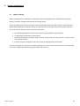
EUDA “All Sky” Camera
Installation and user manual
April 27th, 2015 revision
© Alcor system
1
Table of Contents
1
2
3
4
Camera installation ................................................................................................................................................... 3
1.1
System installation ............................................................................................................................................ 3
1.2
Camera optical settings..................................................................................................................................... 6
1.2.1
Temperature sensor and humidity connector (#1)................................................................................... 7
1.2.2
Power connector and RS232 (#2).............................................................................................................. 7
1.2.3
USB connector (#3) ................................................................................................................................... 8
Software .................................................................................................................................................................... 9
2.1
Camera driver installation software ................................................................................................................. 9
2.2
Installing the camera Software ....................................................................................................................... 11
Using the camera software control ........................................................................................................................ 12
3.1
Initializing ........................................................................................................................................................ 12
3.1
Cooling the CCD .............................................................................................................................................. 19
3.2
General Software Setup .................................................................................................................................. 22
3.3
Camera Control panel ..................................................................................................................................... 24
3.4
Storage of files produced by the camera control software ............................................................................ 27
3.5
Image hot pixel removal using dark frame image........................................................................................... 30
3.5.1
Achieving master dark frame .................................................................................................................. 33
3.5.2
Residual hot pixels repair/fix .................................................................................................................. 36
3.6
Setting the overlay grid ................................................................................................................................... 37
3.7
Cyanogen Boldwood, or Sentinel cloud sensors link with camera control software ..................................... 40
3.8
Magnitude per square second display image mode ....................................................................................... 41
3.9
Telescope control software link ...................................................................................................................... 42
Camera maintenance .............................................................................................................................................. 45
4.1
5
Sphere cleaning ............................................................................................................................................... 45
Product terms of use............................................................................................................................................... 46
© Alcor system
2
1
1.1
Camera installation
System installation
The camera works outdoor, it is totally weather-tight. The camera has mechanical shutter and a 5 positions
filter wheel.
The focusing of the camera can be achieved by software remotely, so there is no need to open the camera to
achieve focusing.
The CCD is has 8.3 million pixel, of 5.4 µm and can be cooled down.
The Iris can be set from f2.8 to f22 by means of software also. Lens focal length is 4.5 mm
The heat from the Sun does not cause daytime stops operation of the camera.
Please do not install the camera near a pollution source (like a chimney). Give as much exposure as possible
and avoid obstacles.
This version of camera has heater that can remove external condensation that can occur on sphere surface.
The camera has three anchors on the back, these three ISO M6 not thru threaded holes by 10 mm depth.
Use the supplied screws to attach it, or equivalent stainless steel A4 or A2 screw.
The whole camera weights 9.5 Kg, so ensure that camera attachment is achieved properly to the mast.
The N, S, E and W direction is defined by rotating the camera accordingly. This is up to the user to define
camera orientation according to its needs. Please perform image capture tests before attaching the camera
to the pole.
© Alcor system
3
Fig. 1 The position of the three screws securing the USB camera (yellow holes) seen from the bottom of the camera
There are three other "holes" that are filled with waterproof connectors, leave this space free and 100mm
underneath to allow the cables to run.
Connectors keying and different amount of pins are preventing connection errors. However, user must look
at the number of connector pins at the end of the cord before connecting the camera, in order to avoid
forcing the pins and damage the camera connector.
Connector
see fig. 1
RED
BLUE
PINK
© Alcor system
Role
Temperature sensor
Power connector and RS232 link
USB 2.0 link to camera
Genre (on camera)
Female
Male
Male
4
Let the cables to go straight from the camera. If the cables shall be bent, respect a minimum curvature
radius of 100 mm.
The waterproof connectors connect as follows:
•
•
•
•
Identify the number of connector pins of the camera, its type (male / female)
Identify the number of pins of the connector cord and match.
Identify the key pin inside the camera connector and the key at the connector cord side.
Apply a rectilinear motion. If insertion force strength persists please repeat steps for
locating the pin number and key. Excessive force applied to connector can cause the
destruction of the connector or a bad connection can damage the camera. In case of
damage due to trials to attach cable to the wrong connector kind, warranty could be
canceled.
Fig. 2 Key one of the three connectors (power connector).
© Alcor system
5
Fig. 3 Push the connector straight
Fig. 4 Then turn the connector’s collar in clockwise fashion
1.2
© Alcor system
Camera optical settings
6
The angle adjustment (tilt) of the camera lens with respect to the CCD plane is factory made.
It is not possible to perform changes from outside for tightness reasons.
The camera iris and focus position is controlled by external software, as well as the 5 position filter wheel
and camera. So this is required to run the Skywatch.exe to gain access to these settings.
1.2.1 Temperature sensor and humidity connector (#1)
It is a 5-pin connector. The probe located at the end of the cord will be placed preferably in the shade, as far
as possible from the camera, and always with two set Ø4mm screws with the direction given in the next
frame and horizontally. It put upside down, this can destroy the sensor and warranty will not apply.
Fig. 5 Up / down and horizontal temperature sensor and humidity directions for installation
1.2.2 Power connector and RS232 (#2)
This is providing power to the camera and RS232 link.
The RS232 connector is a DB9 connector type female and attaches to the serial port of the PC. New PCs are
not equipped with serial port, and must be equipped either:
•
•
© Alcor system
By a RS232 – USB converter (very moderate cost, FTDI, ATEN devices, avoid Prolific, there
are not reliable)
By RS232 PCI card (Low cost device, not suitable for laptops)
7
•
By Serial to Ethernet (MOXA devices, very reliable and professional device
http://www.moxa.com/product/nport_device_server_1.htm ) Product type is Nport.
The RS232 control link is mandatory, and must be connected to your PC. This gives access to:
• dome heating control, temperature and humidity thresholds that will turn on and off the dome
heating
• setting the heat power to be applied to the dome
• reading temperature of different sensors inside and outside camera
• reading relative humidity sensors from inside and outside the camera
• controlling the lens focus position and iris from f2.8 to f22, and the good focus position is set by
Skywatch software on startup (otherwise blurry images will be obtained).
So this is a mandatory control way for the camera. Please connect the RS232 link to your PC.
1.2.3 USB connector (#3)
This is tied up to a 6 pin connector. Please always connect the camera first and then connect to PC second,
with camera turned off. Power the camera once the USB connection is tied both sides. The cable that goes to
the PC is 20m length and is amplified. Connect USB directly to the PC, not thru hub. The USB camera is very
sensitive and does not allows USB ports that reports issues, or been wear off by years of usage. Please be
sure to have installed the latest USB chipset software for your motherboard. Do not put other devices on the
same USB hub that requires some current.
If the camera is not recognized by the PC, try another USB port.
Despite the camera is USB 2.0, USB 3.0 PCI extra board can be used, and since they are very well powered,
most of the time, they work more nicely and more reliably than embedded motherboard USB controllers.
This is an important step, otherwise, the PC can download images for some hours, and then will not anymore
because of the USB link being not reliable.
Alcor-System has a long experience connecting USB devices using a 20m extender, and when it fails, it is
always due to PC issues, with USB chipset drivers, USB hub badly powered, USB port been jeopardized by
several Electro Static Discharge (ESD).
© Alcor system
8
2
Software
Installation process has two parts:
1.
2.
2.1
Camera USB driver
ALCOR-SYSTEM camera software suite (Skywatch, Xvid encoder, ….)
Camera driver installation software
Connect the camera to the USB port of your PC where it needs to work with. In the Windows device
Manager form, the camera should appear with an icon tagged exclamation point on a yellow background.
Fig. 6 Lists of Windows’ devices
If your system is 64 bit PC, the driver must be downloaded here:
http://www.alcor-system.com/common/allSky/sw/GXCam_EN_64.exe
If your system is 32 bit PC, the driver must be downloaded here:
http://www.alcor-system.com/common/allSky/sw/GXCam_EN_32.exe
© Alcor system
9
Fig. 7 USB camera driver files
Once downloaded, start the GXCAM_EN_64.exe or the GXCAM_EN_32.exe according to your system (32 or
64 bits).
Accept all modifications to your system. Do not disconnect the camera during this phase.
Fig. 8
After camera driver is installed, into the device manager, the yellow exclamation point will disappear and
provides the actual name of the camera.
© Alcor system
10
Fig. 9 Windows Device Manager, once the camera driver is installed and loaded properly.
2.2
Installing the camera Software
2.4. Installing the camera control software
The software must be downloaded here:
http://www.alcor-system.com/common/allSky/sw/setup_skywatch.exe
This is the software used to control the camera, click on "setup.exe"
The dot NET 3.0 platform is required; if this is missing to your system, please get it here.
http://www.microsoft.com/download/en/details.aspx?displaylang=en&id=31
© Alcor system
11
Installation is quick and trivial. Please accept all installation modules, also XVID encoder that will allow you to
create time lapses.
The software creates an icon to your desktop. We must double-click it to start the camera control software.
Fig. 10
Also SIPS software can be used to control the camera and the filter wheel, but this is a basic test software and
has not all the features for all-sky cameras, that has Skywatch. The focus and iris control is not possible with this
software. Nevertheless, it can be useful to debug camera link.
http://www.alcor-system.com/common/allSky/sw/SIPS EN 32-bit.exe
http://www.alcor-system.com/common/allSky/sw/SIPS EN 64-bit.exe
3
Using the camera software control
This software is fairly intuitive; the documentation will focus on features that are considered difficult to use,
and about the startup procedure.
Access to the menu bar is located in the upper left, and a flying window in the foreground can quickly adjust
the software settings.
3.1
Initializing
This is an important section, please follow it.
By default, the software sets to simulation camera, and this has to be changed to the proper camera. Click
“Camera Setup”:
© Alcor system
12
Fig. 11
By default, the software is set to simulation camera.
Fig. 12
Select "EUDA V2 Camera"
© Alcor system
13
Fig. 13
The G2-8300 camera must appear, readout mode can be “Low Noise” (slower readout), or “Preview” for
faster readout, but provides more noise.
Then click the "Setup 5 filters" button
Fig. 14
Assign name of the filters to indexes according to your choice on purchase (please contact Alcor-Sytem in
case of purchasing custom filters set).
Then click “OK” and “OK” to validate and exit these forms.
Open then “Options/Dome Heating control / CCD cooling”
© Alcor system
14
Fig. 15
The Serial RS232 COM port must be set to the right value (depending on your system’s settings) and click
“Connect”. If the RS232 link is not working, camera focus, and iris control will not be possible and camera
will provide blurred images!
Fig. 16
If an error occur (not cable tied, or wrongly set port COM), this message will be displayed:
Fig. 17
Otherwise, the window expand and information is displayed as follows:
© Alcor system
15
Fig. 18
Top left shows outdoor temperature and humidity. Those figures will trigger the dome heating. Also the
temperature of the CCD, hot dissipater plate behind the CCD and inner camera are reported.
When the violet curve goes up (vertical red arrow), it means that the dome heating has been enabled, and
stay down when the dome heating is disabled.
The humidity tab, shows the outdoor relative humidity level and inner camera relative humidity. This is not
the humidity that sees the CCD, the CCD is enclosed into a very tight chamber.
© Alcor system
16
Fig. 19
The inner camera relative humidity shall never be above 60% otherwise, dew may form in the inner side of
the dome, and this jeopardizing image quality. On delivery, the camera inner humidity can be very low, less
than 5% because of desiccant presence inside the camera.
The control/setup tab allows to setup threshold temperature and humidity to allow dome heating to be
turned on or off.
© Alcor system
17
Fig. 20
Do not have the dome heating working all the time, during the day, for instance, this is not very useful and
advised, this can wear out the o-ring sealing quicker than expected.
The heating of the sphere is achieved throughout a set of resistors placed under the sphere base. It can
defog or defrost the outside side of the acrylic sphere. The inner side shall not have dew, please refer to the
inner humidity sensor figure.
The system is autonomous (works without link to PC and without user's supervision). It sets out the
conditions when temperature and humidity levels enable occurrence of water condensation.
As soon as the temperature is below a certain value, and moisture above another value, the heating system
is automatically activated. These levels are named temperature and humidity levels.
By default, factory set, the default threshold temperature is set to +7 ° C and humidity level to 90%. These
thresholds may be inappropriate for a given site and can be adjusted by user input.
Similarly, the heating power is set by default to 50% duty cycle, it can be changed according to site and
circumstances.
Beware, if this window is closed, recording data cannot occur anymore. We recommend that you simply
hide it. Nevertheless, dome heater activation is achieved by the camera alone, without any link to the PC.
Finally, it is possible to transfer these plots to website for remote checking.
© Alcor system
18
Fig. 21 Website setting for temperature and humidity plot posting
3.1
Cooling the CCD
The CCD of this camera can be cooled. The benefit is noise reduction and no hot pixels anymore.
This is not necessary to cool down the camera during the day, because exposure time is short enough to
avoid any hot pixels and noise increase, so do not cool down the camera during the day.
The cooling CCD tab lets you to setup CCD temperature, to minimize hot pixels and dark current noise.
Cooling CCD at -10°C is sufficient, and must be used only during the night where long exposures are
achieved.
Maximum exposure to avoid star trailing is between 25 and 35sec.
The mean power of the CCD cooling must not exceed 60% of the power available for cooling.
During the day, CCD cooling must be inactive. This panel has all the features to allow automatically the CCD
cooling to be inactive during the day.
During the night, the temperature to reach can be entered by the user, and during the day, it is set to 30°C,
that will never be reached because the system cools the CCD, and cannot warm it up. The CCD temperature
will be let to follow then inner environment camera temperature.
© Alcor system
19
Fig. 22
Fig. 23
The Focusing, iris and Filter wheel control can be accessed this way:
© Alcor system
20
Fig. 24
Go to the “Filter Wheel” tab, and define the amount of focuser step for each filter. This information is
provided by ALCOR-SYSTEM, but you can refine it if desired.
Warning: if serial Rs232 COM port is not defined properly, the panel will not show up, and no iris and focus
control are possible. The COM port is set by the panel displayed when “Options/Dome Heating control /
CCD cooling” is selected.
The “filter wheel” tab allows to change filter and refocus accordingly, because filters may have not the same
thickness and camera must be refocused. The series of number (1275, 1275, 1275, 1300 and 350 steps) to
refocus after filter changes is provided by ALCOR-SYSTEM.
Fig. 25
The “Iris” tab allows to set the F ratio of the lens as required. During night, it is advised to open it to the
maximum aperture, i.e F2.8, and during the day it can be set to any other figure.
© Alcor system
21
Fig. 26
The “Focus” tab, is meant to change focus on the fly, and see if the image quality improves. Reference to
zero, allows the system to reset focusing because this is not an absolute focusing system, but a relative
encoder from a position. The maximum focus range is from 0 to 1800 encoder’s steps. If you want to save
the new figure, please go back to the “filter wheel” tab.
Fig. 27
3.2
General Software Setup
The get it, please check the next menu
© Alcor system
22
Fig. 28
Set up your geographic place, this is important. It is meant to compute Sun set and Sun rise, and other
astronomical parameters.
In the “Image grab control” group box, the filter for day operation must be set to neutral filter, and during
the night, to a different filter (L, R, G or B) and F ratio.
Recording images during the day with L filter is not possible, the camera exposure time (250ms) does not
allow this. So another filter or neutral filter can be used.
© Alcor system
23
Fig. 29
3.3
Camera Control panel
The control Panel is always visible on the right side of the screen.
© Alcor system
24
The “camera” tab, is important.
Once the camera is selected, the exposures start immediately. Then,
do not forget to check the "Auto Exposure" box after the first image
has been displayed. Here 25 sec of maximum allowable exposure has
been set, so that camera can acquire images during the night of the
day with the proper filter.
The minimum exposure time is 0.25 sec
If the camera is cooled, it is not necessary to check “Remove dark
frame”, “Hot pixels removal”, and “Automatic hot pixels removal”
Fig. 30
© Alcor system
25
The system status provides useful information of the camera.
Exposure status, when the AVI file is going to be generated, and
other information is displayed.
The Focus/Iris/Filter group box is also visible, provided the
camera serial link is connected and the proper COM port being
set.
Fig. 31
If “Automatic exposure” time is checked and “Circular fisheye” is chosen, the computation area
refers to the circle that is defined into the “display” tab in the camera control panel. To see how
this fisheye circle is defined, enable the grid display and set the circle (position center and radius)
so that it matches the image returned by the camera. The automatic exposure time will use the
inner circle area to compute the level for the next exposure time. Do not put more than 25s
exposure time, otherwise star will trail due to the Earth rotation.
© Alcor system
26
Fig. 32
Fig. 33
3.4
Storage of files produced by the camera control software
The software stores all the files it produces into a directory that is specific to the user.
This directory (and subdirectories) is created automatically by the software.
© Alcor system
27
For example, under Windows XP: "C: \ Documents and Settings \ [username] \ My Documents \ SKYWATCH"
with [username] = Name by which you connect on Windows XP.
Fig. 34
Under Windows 7,8,10 or Vista : "C: \ Users \ [username] \ My Documents \ SKYWATCH"
Fig. 35
• The subdirectory AVI: contains the latest videos generated by the camera control software.
• The subdirectory darkframes : contains the images needed for camera hot pixels removal. All CPA
files found there are tried by the software to find the best dark frame to be used to remove camera hot
pixels.
• The subdirectory FTPData: contains the final JPEG image produced to be uploaded on user’s website
© Alcor system
28
• The subdirectory FTPLog: contains the log files generated for each image transfer to the website.
These logs help to find out issues when transferring files to user’s website.
• The subdirectory HotpixelsList: contains the hotpixlist.cos file used to make hot pixel corrections
that were not removed by the subtraction of the optimized dark master frame.
Hotpixlist.cos this is an ASCII file where each line describes the correction to be made to a given X/Y
pixel
For instance:
fill
fill
fill
fill
103
289
304
664
360
570
125
326
1
1
1
1
The first line indicates that the pixel located at X = 103 and Y = 12 and a single pixel size shall be
corrected by its neighbors pixels.
This correction takes into account that the image is a Bayer pattern array (color camera) and picks up
neighbors pixels accordingly.
This file can be automatically generated from a feature from this software (see next paragraph)
• The logs files subdirectory: contains the log files of the software, in which are written the software
actions and events as a text file. This is for debugging purposes. A new file is created each time you start
up the camera control software.
The log file is enabled into the main’s software setup panel. Just enable it in case of issues, because log
file can make large files.
© Alcor system
29
Fig. 36
• The subdirectory Year_month_Day: contains image files that are saved automatically by the
software as jpegs files or CPA/FITS files.
The directory is used from noon to noon. For instance images created from 12:00 on May 10th 2010 till
May 11th, 2010 at 11:59 will all be stored inside 2010_05_10 subdirectory.
3.5
Image hot pixel removal using dark frame image
The camera embeds, in this system, a system to cool down the camera sensor, so following this procedure
in this paragraph is not mandatory.
Production of hot pixels depends mainly on the temperature of the CCD camera that is bound to external
temperature. More the camera is being used under conditions of high temperatures, more the amount of
hot pixels. Exposure time also affects strongly the amount of hot pixels: the higher the exposure time, the
higher the number of hot pixels.
© Alcor system
30
The following series of images is quite demonstrative: in case of a black and white camera, the pixels are
white hot and occupy a single pixel. It is possible to confuse them with stars, but their existence in areas
without light reflects an important problem of image quality.
It is therefore essential to correct these hot pixels using an “dark" master frame, and possibly complete
the task with a list of pixels to fix.
Fig. 37
Fig. 38
Without correction of "dark" and hot pixels
With correction of "dark" and hot pixels
The software performs hot pixels fixing in three ways:
By subtracting a master dark frame.
Local pixel correction from a list of hot pixels
Automatic local hot pixel removal based on two parameters
Activation of these corrections is achieved using the main camera control panel, camera tab, then on the
following checkboxes "Remove dark frame", “Hot pixel removal” based on pixel list coordinates or / and
"Automatic hot pixel removal"
The master dark frame is located in this folder and can be a CPA or a FITS file, later the software can produce
these file for you :
© Alcor system
31
Fig. 39
During day, the dark frame correction is not performed, because negligible dark level.
If no file cannot be found inside this “DarkFrames” folder, if the image file does not have the same size in
width or height, or if not the same pixels type, a message error will be displayed in the status tab of the
control panel.
This dark frame subtraction is performed through an optimization algorithm of the coefficient to be applied
to the master dark frame image. If many files are present, the software will select the master dark frame
that provides a result that is closest to 1.0.
Fig. 40
The software scans the presence of files in the DarkFrames folder and will automatically pick up the most
appropriate file.
This means that if the master dark frame was produced at a given temperature, a given exposure time and a
given gain, the software is able to optimize the subtraction of the current image by the best dark frame,
even if there was temperature changes. This is performed within a reasonable range of variation. It will be
discussed later on the effects and validity of the dark master frame according to the variation of parameters.
As there are still hot pixels that have non-linear behavior and cannot be corrected by the dark master frame,
correction using hot pixels list can be achieved, cleaning the image of hot pixels by its neighbors.
Just check the box highlighted in the screenshot below.
© Alcor system
32
Fig. 41
The file used for this operation can be found here:
Fig. 42
This is a text file, contains a list of hot pixels to repair/fix.
3.5.1 Achieving master dark frame
The files located into DarkFrames folder, whose fundamental purpose has been presented above, may, in
some cases no longer be adapted to the current image shooting conditions (due to seasonal temperature
changes). This is especially the temperature change that will determine the validity of the master "dark"
frame. This validity is above/below 5°C the temperature where the master dark frame has been recorded.
Beyond this temperature range, the image hot pixel repair/removal using this dark frame might become
poor and not effective.
For example, a master "dark" frame recorded from a set of some dark images at 20 ° C will be valid for
images acquired between +15 °C to +25 °C.
It is better to build a small library of "dark master" for each 5°C (outdoor temperature)
The software will automatically select the most appropriate in the “DarkFrames” folder.
How to make a master "dark" frame for a given outdoor temperature?
This is easy. Under “Camera” tab, uncheck "Auto Exposure time" and select an exposure time
corresponding to the longest exposure time used during night, for example 30s and then do "Apply"
© Alcor system
33
Fig. 43
Operate ONLY during night and cover the system (the Plexiglas dome) with a black tissue, or black paper. Be
sure that any stray light cannot penetrate to the camera lens. Warning, it's a fisheye that is mounted on the
top of the camera, and it able to see 360 ° down to the horizon!
A feature has been implemented to achieve a master dark frame, and also can compute a list of hot pixels
too.
Press the "Dark frame recording mode" and check "Do median stack of" say 5 to 11 "darks".
Fig. 44
The software switches into a particular mode that allows it to produce "dark" frames and performs the
median stack when the amount a required dark frames have been reached in order to achieve a dark master
frame and a list of hot pixels.
© Alcor system
34
Fig. 45
The resulting files are placed in the proper directories and are immediately ready for use.
Once the task is complete, click on "Normal mode"
Enable the following features by checking the following boxes:
Fig. 46
For each image recorded by the camera, the dark master frame file will be used in the form:
Displayed_image = Raw_Image_brute - k * Master_dark_frame_Image
Where k is a coefficient optimized by the software.
More k is close to 1, the better. In the following scenario, k = 0.95, which is a good value.
Fig. 47
If k> 1.5 or k <0.5, it means that the master dark frame is not well appropriate to the current outdoor
temperature conditions. A warning message will be displayed as a red sentence.
© Alcor system
35
3.5.2 Residual hot pixels repair/fix
Despite the subtraction by a master dark frame, and the repair of hot pixels based on a list of coordinates,
some hot pixels are still variable (appear and disappear from one frame to another). To remove these last
hot pixels that can’t be removed previously, the next checkbox shall be enabled:
Fig. 48
The algorithm automatically eliminates hot pixels by inspecting all pixels from the incoming image. Two
parameters to set two conditions are necessary.
The first parameter defines the difference of the pixel compared to its eight neighbors for which that pixel will
be considered as potential hot pixels because it exceeds the defined gap (as ADU).
The second parameter sets the maximum standard deviation of the eight neighboring pixels, if the deviation
is less than the defined value; the central pixel is considered as potential hot pixel.
When the two above conditions are met, the hot pixel is fixed automatically.
Fig. 49
The figure above shows that the automatic correction is performed on average into one pixel every 69x69
pixel box. To test this feature use a moonless night, and be careful not to remove some stars of the picture
by setting a too low maximum gap and too high standard deviation !
You can see how these fixed pixels are spread over the image, by enabling the following checkbox.
© Alcor system
36
Fig. 50
A pixel density corrected that implies one pixel every 7x7 pixels box is maximum, beyond this density, such
as one pixel each 5x5 pixel, the image quality is highly jeopardized, and master "dark" frame and the list of
hot pixels bound to it must be achieved.
3.5.
Status information
In JPEG image, a cartridges are indicating camera statuses, "2129" indicates the number of images taken
since the software has been started up.
"D 1.6" indicates a correction by a factor 1.6 of the dark frame; "H" indicates hot pixel correction using a list,
for example "18x18 H" indicates that an average of one pixel of 18x18 pixel bow is repaired. If H! is
displayed, this means that the hot pixel file was not found. The “L 9x9" indicates an automatic correction of
hot pixels having an average density of 1 pixel per 9 by 9 pixels.
Fig. 51
Fig. 52
3.6
Setting the overlay grid
The camera must be installed vertically using a water “bubble” level. Otherwise, the setting of this grid
will be difficult and will not match actual image.
Here is the recommended way to set the grid that is used to identify stars on the image: this is not an
automatic procedure, this setting shall be performed manually. But once set, this will be set forever (expect
the camera is being moved or rotated). In the Control Panel, set the location, latitude and longitude,
© Alcor system
37
altitude, and the country.
Fig. 53
•
•
•
•
•
© Alcor system
Use night time when a star of magnitude 0 to 3 passes to zenith (or say +/- 2° from the zenith)
Force fixed exposure time of 5s to 10s
Get to "Enable grid display" and "Show Main object" (Check “Only horizon”)
Find the star that passes nearby zenith and move the cross indicating zenith towards it.
Change “X center” and “Y center” figures so that the cross position matches with the star.
38
Fig. 54 Displacement in X and Y to adjust the position of the zenith symbol
Fig. 55 Star passing nearby zenith (Deneb) and zenith marker
•
© Alcor system
Once the zenith marker found, you have to set the "north position" to have the grid (circle and
star’s name) matching with star position. The grid scale can be changed also.
The grid (or set of stars position) is changing according to the time and geographical
coordinates. Be sure to have set theses parameters correctly.
39
Cyanogen Boldwood, or Sentinel cloud sensors link with camera control software
3.7
If you own a cloud monitor from Cyanogen or Shelyak companies, it is possible to display, at the top right of
the image, some weather information. In the main Setup Panel, enter appropriate information. The software
uses simply the output file generated by each measurement from cloud sensor. It does not use the COM or
ActiveX interface. Enter the path of the generated file provided by the software that runs the cloud sensor.
The amount of information depends on the system that is measuring cloud cover. It will be the most
complete using Sentinel Shelyak system (wind direction and zenith magnitude per second squared).
Fig. 56 Group of information to provide to connect with cloud sensor system control software.
© Alcor system
40
Fig. 57 List of information coming from Sentinel or Boltwood
cloud sensor included in the image
Magnitude per square second display image mode
3.8
The software allows the calculation of radiometric magnitude per square second across the sky. It works on
color and monochrome cameras. In case of color image, only green pixels will be considered (50%).
To do so, you have to open this tab:
Fig. 58 Tab used to set magnitude image mode display
The calculation is based on a reference image, with reference parameters. To perform this, a reference
image is achieved with:
•
•
© Alcor system
An exposure time reference
A camera gain reference
41
•
•
•
•
•
Opening aperture reference (which is usually fixed as the aperture setting is not accessible).
Subtracting the reference image by a master dark frame
The camera gamma adjustment must be set to 100.
Avoid the presence of Milky Way overhead.
Save reference image as CPA / FITS
Using this reference image, the signal is expressed as ADU. Nearby zenith the signal is measured and is
reduced to a pixel, and must be entered in the panel from figure (Fig. 59) “Reference pixel signal” field.
It is advisable to use image processing software (such as Prism or equivalent).
At the time of reference image acquisition (during night), using a sky meter measuring device such as
Sentinel or SkyQualityMeter (Unihedron), the magnitude per square second will be retrieved and entered as
a reference “Reference Magnitude per arcsec²”.
The coefficients "A" (0358) and "B" (0.004045) are specific to the camera law gain and might remain at their
default values above, but can be re-calibrated in laboratory for a specific camera.
Once the calibration parameters known, the software calculates the magnitudes map per square second
from the last image grabbed from the camera. Median filtering is performed to remove most of the stars.
The image pixels are expressed in magnitude per square second, a false-color palette is applied and a color
scale indicates the color to magnitude correlation.
Fig. 60 Map of the sky expressed as magnitudes per arcsec square with false colors.
3.9
© Alcor system
Telescope control software link
42
Telescope's pointing direction can be display and embedded to the last all Sky Image. The telescope pointing
software shall be able to generate a simple text file, containing date and time of the measured position and
equinox 2000 RA/DEC coming from the telescope current position.
Fig. 61 Current telescope position merged to the last all Sky image
If the time gap between the current date and the date of the last telescope position is greater than 10s, the
telescope’s cross position switches to red color, indicating that the position is no longer refreshed by the
software, and thus might not be valid.
Fig. 62 Telescope position as red because current date and telescope position date is larger than 10s
Here is the file format used to read telescope position as ASCII file, 1st line is amount of days since Dec 31st
1899 at 12 o’clock, the second line is RA as radian, the third line is DEC as radian:
40307.9796818056
4.3461698620
0.9539777407
UTTime = 09/05/2010 11:30:44 p.m.
RA2000 = 16h36m04.126s
DEC2000 = +54 ° 39'32 .03''
The other remaining lines are not read and are just provided for information.
© Alcor system
43
Fig. 63 Telescope’s names can be set in this form
© Alcor system
44
4
Camera maintenance
Sphere cleaning
4.1
Sphere cleaning must be achieved on regular basis. Rains can bring dust that is deposited on the sphere
surface; it reduces the optical transmission and image quality.
The acrylic sphere outer and inner surface can be cleaned with water, then with a Kleenex moistened with
washer fluid dedicated for window cleaning. The 8 screws can be removed to detach the sphere from the
rest of the camera. Attention must be paid on these topics:
•
•
•
The cable bringing power to the heaters should not be pinched during reassembly
•
8 screws must be put together with their washer and all tightened the same way.
O-rings properly positioned in their grooves
The distance between the sphere support and the camera body must be at least 3 mm and constant
around the perimeter.
Incorrect reassembly can cause loss of sealing, allowing rain to enter and de facto guarantees no longer apply.
If you feel confident with dismounting sphere, please do not do it.
© Alcor system
45
5
Product terms of use
The use of this product is solely for monitoring the sky, night and day, entertaining, educational or scientific
purposes.
Use of this product involving people's lives is the responsibility of the user and in no way ALCOR SYSTEM will
be held liable for injuries to persons or property theft as the use of this camera described in this manual.
---0O0---
© Alcor system
46