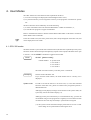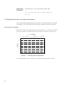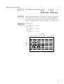
1
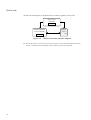
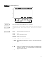
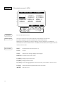
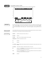
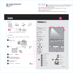
OPERATING UNIT OPU-320 Rev. 2 EM01OP900F vii OPERATING UNIT OPU-320 Rev. 2 Copyright © 1998-2001 SEIKO EPSON CORPORATION. All rights reserved. i WARRANTY The robot and its optional parts are shipped to our customers only after being subjected to the strictest quality controls, tests and inspections to certify its compliance with our high performance standards. Product malfunctions resulting from normal handling or operation will be repaired free of charge during the normal warranty period. (Please ask your Regional Sales Office for warranty period information.) However, customers will be charged for repairs in the following cases (even if they occur during the warranty period): 1. Damage or malfunction caused by improper use which is not described in the manual, or careless use. 2. Malfunctions caused by customers’ unauthorized disassembly. 3. Damage due to improper adjustments or unauthorized repair attempts. 4. Damage caused by natural disasters such as earthquake, flood, etc. Warnings, Cautions, Usage: 1. If the robot or associated equipment is used outside of the usage conditions and product specifications described in the manuals, this warranty is void. 2. If you do not follow the WARNINGS and CAUTIONS in this manual, we cannot be responsible for any malfunction or accident, even if the result is injury or death. 3. We cannot foresee all possible dangers and consequences. Therefore, this manual cannot warn the user of all possible hazards. SERVICE CENTER Contact the following service center for robot repairs, inspections or adjustments. Please have the model name, “Serial No.” or “M.CODE”, software version and a description of the problem ready when you call. If service center information is not indicated here, please contact the supplier office for your region as listed in the following SUPPLIERS section. ii SUPPLIERS Japan & Others SEIKO EPSON CORPORATION Okaya Plant No. 2 1-16-15, Daiei-cho Okaya-shi, Nagano-ken, 394-0025 Japan TEL: FAX: 81-266-23-0020 (switchboard) 81-266-24-2004 (direct) 81-266-24-2017 North & South EPSON AMERICA, INC. America Factory Automation/Robotics 18300 Central Avenue Carson, CA 90746 TEL: (562) 290-5900 FAX: (562) 290-5999 E-MAIL: [email protected] Europe EPSON DEUTSCHLAND GmbH Factory Automation Division Zuelpicher Str. 6 D-40546 Duesseldorf TEL: (++) 49 - 211 - 5603 391 (Inside Sales) FAX: (++) 49 - 211 - 5603 444 E-MAIL: NOTICE [email protected] No part of this manual may be copied or reproduced without authorization. The content of this manual is subject to change without notice. We ask that you please notify us if you should find any errors in this manual or if you have any comments regarding its content. TRADEMARKS Microsoft is a registered trademark and Windows and Windows logo are registered trademarks of the Microsoft Corporation. Other brand and product names are trade- marks or registered trademarks of the respective holders. Please direct any inquiries about the use of this manual to: Operating Unit OPU-320 SEIKO EPSON CORPORATION. Sales Engineering Group TEL:81-266-24-2004 FAX:81-266-24-2017 iii Safety Precautions Please carefully read this manual and other related manuals before using this equipment. After reading the manual, store it in a convenient place so that you can refer to it at any time. WARNING - Before using the OPU-320, be sure to confirm that the emergency stop switch functions properly. - Do not hesitate to push the emergency stop switch when you sense danger. CAUTION - Please handle the OPU-320 with sufficient care, as it is a piece of electronic equipment equipped with a liquid crystal display. (1) Please do not subject the OPU-320 to physical shocks. The liquid-crystal display is particularly susceptible to damage from physical shocks. (2) Please do not place any object on top of the OPU-320. - The OPU-320 must be used in a suitable environment for it to function safely and as intended. Please install it in an environment that satisfies the requirements specified in this manual. Please do not use the OPU-320 in any other kind of environment. - Make certain that the power to both the OPU-320 and the controller is off before you connect or disconnect cables. Connecting and disconnecting cables while power is on may cause equipment failure. - Make certain that all cables are connected securely. Please avoid placing heavy objects on cables or taking any other actions that could damage them. Damaged or abnormal cables are hazardous, as they could cause the robot to operate improperly. - The person who enters inside the manipulator safe guard for teaching shall remove the mode switching key from the OPU-320 after switching to the TEACH mode, and shall keep the key with him/her when entering inside the guard. This is for preventing the person from the danger that the mode will be switched to an automatic operation by mistake. If TP-320 is used in this case, attach the OPU-320's key to the key holder of the TP-320. iv FOREWORD This manual specifies matters that you need to know to use the operating unit correctly. Please thoroughly read this and other related manuals before using the equipment. MANUALS 1. User's manual A manual that gives a general description of robots. It describes such things as safety precaution, operating methods, teaching methods, programming methods, and file management. Please read the user's manual first. 2. Manipulator manual A manual for the manipulator itself. The basic volume describes the safety tips to be observed by the user prior to/in setting up the equipment. The maintenance volume describes the maintenancce procedure and part replacement. 3. Robot controller manual A manual that describes the robot controller who executes an operating software and controls I/O and the servo-mechanism. The functions volume describes connecting the robot to the peripheral equipment and basic robot settings. The maintenance volume describes the such things as a power supply circuit schematics, parts replacement, trouble shooting, etc. 4. Reference manual A manual that describes the commands for the SPEL III robot language. 5. Operating unit manual (option) A manual for the operating unit that describes such things as operating methods. 6. Programming support software manual (option) A manual for the program development support software. It describes such things as operating environments and operating methods for SPEL Editor or SPEL for Windows. We provide two kinds of software, SPEL Editor (for MS-DOS) and SPEL for Windows (for Microsoft Windows). We also provide Vision Guide, the integrated robot vision system, as an option of SPEL for Windows. 7. Teaching pendant manual (option) A manual for the teaching pendant. It describes such things as how to operate the teaching pendant. v Differences with the OPU-300 OPU-320 is an operating unit made exclusively for the SRC-300, SRC-310A and SRC320 controller. OPU-320 is a successor model to OPU-300. Added features and the differences from OPU-300 are as follows: - The new LCD panel has attained higher contrast and improved visibility. - Emergency stop switch with safety lock The emergency stop switch has improved. The new emergency stop switch comes with a safety-lock feature in which the contact would not be activated until the push button is completely locked. This prevents malfunction due to an operator’s wrong operation or contact with other utensils. - Although the depth dimension is slightly longer than OPU-300 to implement the above new features, there is no changes to the mounting dimensions and the positioning of the fixing screws. Please refer to the External Dimensions for further details. Depth: 43 to 53 mm Emergency stop switch protrusion: 16 to 25 mm vi TABLE OF CONTENTS 1. Before Using This Equipment 1.1 1.2 1.3 1.4 1.5 1.6 1.7 Unpacking What is the OPU-320 Part names and functions Environmental conditions Cable connections Contrast Safety 2. Modes and Consoles 2.1 Controller modes 2.2 The console during auto mode 2.3 State transition diagram 1 1 1 2 4 4 4 5 6 6 6 8 3. Example Screen Displays and Operating Procedures 12 4. User Modes 38 4.1 4.2 4.3 4.4 OPU-320 modes Determination of key states Displaying characters on the liquid-crystal display Escape sequence 5. Specifications 5.1 Standard specifications chart 5.2 External dimensions diagram 38 39 40 44 48 48 49 vii viii 1. Before Using This Equipment 1.1 Unpacking Contents OPU-320 Mode switching key Cable (standard: 3 m) This manual ×1 ×2 ×1 ×1 The operating unit is a piece of delicate electronic equipment and is equipped with a fragile LCD (liquid-crystal display) panel. Please handle it with sufficient care. CAUTION (1) Do not subject the OPU-320 to physical shocks. The LCD panel is particularly susceptible to damage from physical shocks. (2) Do not place any object on top of the OPU-320. 1.2 What is the OPU-320 The OPU-320 is an operating unit designed exclusively for our SRC-300, SRC-310A and SRC320 robot controller. In addition to all the basic functions, such as start and stop, the OPU-320 also has as a standard feature a large LCD panel that enables it to display a variety of information. OPU-320 features - A large LCD panel capable of displaying a large amount of information at once. - Display of file name and selection of file for execution using cursor key. - I/O and task monitor function. - On-screen description of the content of errors. - Ability to freely display characters from the user's program on the liquid-crystal display. 1 1.3 Part names and functions (1) (16) OPU-320 (2) EMERGENCY STOP (10) EMG.STOP SYSTEM ERROR ERROR (11) SAFE GUARD MOTOR POWER HOME (12) (13) RESET (14) PAUSE OPERATION MODE TEACH F1 AUTO F2 F3 (15) F4 START (3) MONITOR (9) (8) (7) (4) (6) (5) Fig. 1.1 Part names (1) Liquid-crystal display Displays various information. The screen can display up to eight lines of 32 characters each. The name of the program being executed, mode, screen title, and other information is displayed at the top of the screen. The functions of the function keys are displayed in reverse (on a black background) on the bottom of the screen. Users are free to display the characters of their choice on the liquid-crystal display. (2) EMERGENCY STOP switch An emergency stop switch. When this switch is pushed, the emergency stop state is held both mechanically and electrically. Pushing the switch stops the program, halts robot excitation, and causes the robot to come to a quick stop. The EMG. STOP and RESET LEDs light up and the screen display switches from the Program Execution Screen to the Reset Screen (*1). To cancel the emergency stop, first turn the EMERGENCY STOP switch to the right to release the mechanical hold. Then push the RESET switch to cancel the electrically-held emergency stop. The EMG.STOP LED goes off. (*1) Reset Screen: The basic screen when the controller is in the reset state (robot stop state). (3) RESET switch 1. Stops execution of a program during the pause state and switches the display to the Reset Screen. 2. Switches various kinds of screen displays that are in the reset state to the Reset Screen. 3. Cancels the emergency stop state. 2 (4) PAUSE switch Temporarily halts execution of a program. When the PAUSE switch is pushed during execution of a multitask program without specifying the HTASK, all tasks are temporarily halted. When the HTASK command is used to specify the tasks which are to be temporarily halted, only these tasks are halted and the execution of all other tasks continues undisturbed. (5) START switch Executes a program when in AUTO mode. Also used to restart after a pause. (6) MONITOR switch Monitors various states. (7) Function keys Select and execute the functions displayed in reverse (on a black background) on the bottom of the screen. (8) Arrow keys Move the cursor and program number up or down. (9) Mode selector switch with key Selects the operation mode, either AUTO or TEACH. You can lock the mode into place by removing the key. If you switch the mode while a program is being executed, the program stops. (10) EMG. STOP LED Lights up during the emergency stop state. (11) SYSTEM ERROR LED Lights up when there is an MPU abnormality. When this LED is illuminated, such things as the error code display do not function properly. Turn off the power immediately. (12) ERROR LED Lights up when an error occurs. (13) SAFE GUARD LED Lights up when the safeguard is open (when the safety door input of the robot controller is open). (14) MOTOR POWER LED Lights up when the motor is excited. (15) HOME LED Lights up when the robot is in the home position (the position specified by HOMESET). (16) REMOTE connector A connector terminal for connecting the OPU-320 to a controller. Connect to the REMOTE2 connector on the rear panel of the controller. 3 1.4 Environmental conditions The OPU-320 must be used in a suitable environment for it to function safely and as intended. Please install it in an environment that satisfies the requirements specified in this manual. Ambient temperature 5 to 40°C (with minimal variation) Ambient relative humidity 10 to 80 % (with no condensation) Electrostatic noise less than 5 kV (condensor charge method) Momentary power interrupt 10 ms (maximum) Environment · Keep away from direct sunlight · Keep away from dust, oily smoke, salinity, metal powder and · · · · Space other contaminants Keep away from flammable or corrosive solvents and gases Keep away from water Do not subject to physical shocks or vibrations Keep away from sources of electronic noise When installing the OPU-320, leave a space of at least 60 mm above the cabinet for cable connections. 1.5 Cable connections CAUTION - Make certain that the power to both the OPU-320 and the controller is off before you connect or disconnect cables. Connecting and disconnecting cables while power is on may cause equipment failure. - Make certain that all cables are connected securely. Please avoid placing heavy objects on cables or taking any other actions that could damage them. Damaged or abnormal cables are hazardous, as they could cause the robot to operate improperly. Please read the manuals for both the robot and the controller before connecting cables. After reading the manuals, connect the OPU-320 to the controller using the cable that was included with the OPU-320. Plug the cable into the REMOTE2 connector on the rear panel of the controller. 1.6 Contrast Contrast is adjusted at the factory. However, if for some reason it is necessary to adjust the contrast of the liquid-crystal display after you have received the operating unit, you can do so by inserting a thin, flat screwdriver into the small, contrast-adjustment hole on the rear of the OPU320 cabinet and turning the screwdriver right and left while looking at the liquid-crystal display to make fine adjustments. 4 1.7 Safety Emergency stop WARNING - Before using the OPU-320, please confirm that the emergency stop switch functions properly. - Do not hesitate to push the emergency stop switch when you sense danger. When the emergency stop switch is pushed, the execution of programs stops and robot excitation ceases. Programs and point data and such will not be damaged. When pushed, the emergency stop switch mechanically holds that state and electrically holds the emergency stop state. Please cancel the emergency stop by following the procedures below when you want to restart work. You do not have to turn off the equipment to cancel the emergency stop state. (1) Remove the cause so that you can cancel the emergency stop. (2) Cancel the mechanical hold by turning the emergency stop switch to the right. (3) Push the RESET switch. Mode selector switch with key ) NOTE Please do not switch modes while a program is being executed. (In other words, do not turn the key.) The program stops if you switch modes while the program is being executed. Motor power status display (For controller SRC-310A or SRC-320 only) If the controller is SRC-310A or SRC-320, OPU-320 always displays the motor power status except for the setting of user mode. ) NOTE Motor power status is not displayed when the controller is SRC-300 or SRC-310. L : Low power mode H : High power mode Refer to "4.2 Safety door input functions" of controller manual for state transition of motor power. 5 2. Modes and Consoles 2.1 Controller modes The controller has two modes: TEACH mode, which is exclusively for teaching and programming, and AUTO mode, which is for factory operation. Futher, in AUTO mode there are a number of possible consoles to choose from. When either an RS-232C (#20 or #21) or the bus is assigned as the console, it is called S. NET mode. TEACH AUTO REMOTE2 (OPU-320) REMOTE3 (I/O) RS-232C #20, #21 S. NET BUS (Serial bus) You can switch between the AUTO mode and TEACH mode by turning the key of the mode selector switch on the OPU-320. Select the mode when the controller is in the reset state (stop). If you switch the mode while it is running (a program is being executed), it will stop running, and the mode reset screen for the selected mode will be displayed on the OPU-320. In TEACH mode, the TEACH connector on the front panel of the controller is the console. The connected equipment is either a personal computer running SPEL Editor/SPEL for Windows, a program development support software, or Teaching pendant TP-300/TP-320. What is the console You can connect a personal computer, OPU-320, user remote (REMOTE3) or other equipment to the controller and from each piece of equipment execute (start) programs and implement pauses, continuos execution, stops and other operations. The console is defined as both the piece of equipment that performs these operations and the connector by which that equipment is connected. 2.2 The console in AUTO mode The console in AUTO mode is assigned from among the following. OPU-320 (REMOTE2) I/O-1 (REMOTE3) RS-232C #20 RS-232C #21 Serial bus In the default setting, the OPU-320 is the console. Please see the robot controller manual and reference manual for an explanation of how to select another console. 6 When a piece of equipment other than the OPU-320 has been assigned as the console in AUTO mode, all OPU-320 functions except the {PAUSE/START} input and monitor functions become invalid. Whether a function of OPU-320can be used or not is displayed for each console assignment in AUTO mode. In AUTO mode Console OPU-320 In TEACH mode PAUSE START MONITOR PAUSE START MONITOR a a a c b a In AUTO mode Console SS1-1 PAUSE REMOTE3 START In TEACH mode MONITOR PAUSE START MONITOR OFF c c a c c a ON a b a c b a In AUTO mode Console RS-232C #20 RS-232C #21 BUS SS1-1 SS1-2 PAUSE In TEACH mode START MONITOR PAUSE START MONITOR OFF OFF a b a c b a OFF ON a b a c b a ON OFF c c a c c a ON ON a b a c b a Meaning of symbols PAUSE, START, MONITOR : Switches on the OPU-320 a : input valid b : only restart after pause is valid (except pause executed by [Esc] key) c : input invalid Software switch Function On Off SS1-1 Selection of main remote REMOTE3 (I/O) REMOTE2 (OPU) SS1-2 Input function of subremote Pause and restart are valid All input is invalid Use SPEL Editor/SPEL for Windows to set software switches. Refer to the SPEL Editor or SPEL for Windows manual for a description of the setting method. There are two remotes, REMOTE2 (OPU) and REMOTE3 (I/O). Select one as the main remote (console). The remote that was not selected is called the subremote. You can use some subremote functions by turning on SS1-2. 7 2.3 State transition diagram The OPU-320 is equipped with such things as a file selection and execution function and a monitor function for all states. You can use these functions by pressing function keys in accordance with the menu displayed on the OPU-320 screen. Therefore, the OPU-320 has a large number of screens for each function. Here, we show the screen transition diagram for each console assignment in AUTO mode. ) NOTE The state transition diagram (screen) of TEACH mode is the same regardless of the console assignment in AUTO mode. When power is turned on, the reset screens of each state transition diagram are displayed. The proper way to read the state transition diagrams is as follows. A solid line with arrows on both ends means that the screen can be switched in both directions. A dotted line with an arrow on only one end means that the screen can only be switched in one direction. Screen 2 8 The screen number is shown on the bottom of each screen frame. Examples of all screen displays and operation methods in those screens are explained in "3. Examples of all screens and their operating method". Please look up the screens using this screen number. Also use this screen number to reference switching of screens in the state transition diagrams in "3. Examples of all screens and their operating method". AUTO mode Console Reset screen (OPU) OPU-320 Screen 1 File selection screen 1 File selection screen 2 Screen 2 Screen 3 Monitor screen (*1) Figure 2.1 Console REMOTE3 Program execution screen (OPU) Step execution task selection Screen 4 Screen 5 AUTO mode (OPU) state transition diagram You can set up and use the remote function in I/O-1. When I/O-1 is used like this, it is referred to as REMOTE3. Reset screen (REMOTE3) Screen 6 Program execution screen (REMOTE3) Monitor screen (*1) Screen 7 Figure 2.2 Console RS-232C #20 RS-232C #21 BUS AUTO mode (REMOTE3) state transition diagram When the console is either of the RS-232C (#20, #21) connectors or the bus in AUTO mode it is called S. NET mode. Reset screen (S. NET) Screen 8 Program execution screen (S. NET) Screen 9 Figure 2.3 Monitor screen (*1) AUTO mode (S. NET) state transition diagram (*1) The monitor screen is one of the screens shown in Figure 2.5 (State transition diagram for monitor screens). The monitor screen displayed is the screen that was previously monitored. 9 TEACH mode The state transition diagram for TEACH mode is as follows regardless of the console. Reset screen (TEACH) Screen 10 Program execution screen (TEACH) Screen 11 Figure 2.4 Monitor screen (*1) TEACH mode state transition diagram (*1) The Monitor Screen is one of the screens shown in Figure 2.5 (State transition diagram for monitor screens). The Monitor Screen displayed is the screen that was previously monitored. 10 Monitor selection screen Screen 12 Task monitor screens Task line number monitor screen Screen 13 I/O monitor screens Memory I/O monitor screens Input port bit monitor screen Screen 17 Memory I/O bit monitor screen Screen 21 Task line number and status monitor screen Monitored device selection screen Screen 24 Output port bit monitor screen Screen 14 Screen 18 Task line number, status, source program monitor screen Input/Output port byte Memory I/O byte monitor screen Screen 22 monitor screen Screen 19 Screen 15 Task status display format selection screen Screen 16 selection screen Memory I/O status display format selection screen Screen 20 Screen 23 I/O status display format Use the MONITOR key to switch to the monitor screen. The monitor screen that is displayed is the last screen that was monitored. For example, if you leave the monitor screen when screen 17 is being displayed and then switch back to the monitor screen, screen 17 will be displayed again. The screen being monitored is kept in memory even when power is shut off. When you select the task monitor screen on the monitor selection screen (screen 12), either screen 13, screen 14, or screen 15 will be selected. The selected screen corresponds to the last of the task monitor screens to have been monitored. For example, when you switch to the monitor selection screen (screen 12) from screen 14 and then reselect the task monitor screen, screen 14 is displayed. The default screen of each monitor is as follows: 11 3. Example Screen Displays and Operating Procedures In this chapter we shown screen display examples and describe operations which can be 1 performed from these screens. AUTO Mode 2 3 4 OPU(OPU-320) 5 Screen 1 6 Screen 2 7 Screen 3 8 Screen 4 Screen 5 Reset screen (OPU) File selection screen 1 (OPU) File selection screen 2 (OPU) Program execution screen (OPU) Step execution task selection screen (OPU) F1 F2 F3 13 14 15 16 17 F4 × REMOTE3 (I/O-1) Õ Screen 6 Screen 7 MONITOR Ø Ö Reset screen (REMOTE3) Program execution screen (REMOTE3) 18 19 Description S. NET (#20, #21, BUS) Screen 8 Screen 9 Reset screen (S. NET) Program execution screen (S. NET) 20 21 Screen 10 Screen 11 Reset screen (TEACH) Program execution screen (TEACH) 22 23 Screen 12 Screen 13 Screen 14 Screen 15 Screen 16 Screen 17 Screen 18 Screen 19 Screen 20 Screen 21 Screen 22 Screen 23 Screen 24 Monitor selection screen Task line number monitor screen Task line number and status monitor screen Task line number, status, and source program monitor screen Task status display format selection screen Input port bit monitor screen Output port bit monitor screen Input/Output byte monitor screen I/O status display format selection screen Memory I/O bit monitor screen Memory I/O byte monitor screen Memory I/O status display format selection screen Monitor device selection screen 24 26 27 28 29 30 31 32 33 34 35 36 37 TEACH Mode Monitor 12 Screen 1 Reset screen (OPU) 1 2 3 4 5 6 7 8 01TEST Task00[00000] OPU FILE M ON HOME MCAL F1 F2 F3 F4 × Õ Description Screen Layout Key Functions Ø Ö MONITOR Reset screen when the OPU-320 is the console in the AUTO mode. The top line shows, from left to right, the execution file name, task number, line number, and console name (OPU-320). The line number is always zero. The bottom line shows the function menu. RESET : Clears the screen, and shows Screen 1 again. PAUSE : Invalid. START : Executes the program (screen 4). MONITOR : Switches to the monitor screen. F1 (FILE) : Changes to file selection screen (screen 2). F2 (M ON) : Turns motor power on and off. (MOFF) (Displays the opposite motor status to the present = motor status in the function menu.) F3 (HOME): Moves to stand-by position. F4 (MCAL) : Returns to origin. ÏÐ : Switches to the file selection screen (screen 3) for files having numerals for first two characters of file name. Does not switch if there are no execution files with numerals as first two characters. ÍÎ : Invalid. 13 Screen 2 File selection screen 1 (OPU) 1 2 3 4 5 6 7 8 FILE SELECTION A:\ROBOT\ < .. > <TEST> <DUMMY> 01TEST 02MOUNT 05_DUMMY 09ABCDEF 25BIN_10 26BIN_11 30RH99 40RH99 50RH99 ------------------------------------------------PREV NEXT LOAD EXIT F1 F2 F3 F4 × Õ Description Ø Ö MONITOR Execution file selection screen. Screen Layout The top line shows the screen title and directory containing the execution files. Lines three through six show files and directories which can be selected. Subdirectories are indicated by <Directory Name> and root directories are indicated by < .. >. The bottom line shows the function menu. F1 (PREV) and F2 (NEXT) do not appear when the number of files is small. Key Functions RESET : Switches to the reset screen (screen 1). PAUSE : Invalid. START : After an error message, displays screen 2 again. MONITOR : Switches to the monitor screen. F1 (PREV) : Displays the previous screen. F2 (NEXT) : Displays the next screen. F3 (LOAD) : Selects the highlighted file as the execution file, and switches to the reset screen. F4 (EXIT) : Cancels file selection, and switches to the reset screen. ÍÎÏÐ 14 : Move the cursor. Screen 3 File selection screen 2 (OPU) File Selection Screen for files having numerals for first two characters of file name. 1 2 3 4 5 6 7 8 FILE SELECTION 01TEST PRG.NO LOAD EXIT F1 F2 F3 F4 × Õ Description Ø Ö MONITOR Execution file selection screen for files with numerals for first two characters (file number) of file name. Pushing the Ï key searches for file numbers in ascending order while pushing the Ð key searches for file numbers in descending order. The file name appears on the right side of the top line. Screen Layout The left side of the top line shows the screen title, and the right side shows the name of the file being referenced. The bottom line shows the function menu. Key Functions RESET : Switches to the reset screen (screen 1). PAUSE : Invalid. START : After an error message, displays screen 3 again. MONITOR : Switches to the monitor screen. F1 : Invalid. F2 : Invalid. F3 (LOAD) : Selects the file shown in the top line as the execution file, and switches to the reset screen. F4 (EXIT) : Cancels file selection, and switches to the reset screen. Ï : Searches in ascending order for files having numerals as the first two characters and displays the file names in the top line. Ð : Searches in descending order for files having numerals as the first two characters and displays the file names in the top line. ÍÎ : Invalid. 15 Screen 4 Program execution screen (OPU) 1 2 3 4 5 6 7 8 01TEST Task01[01000] OPU CONT STEP TASK F1 F2 F3 F4 × Õ Description Ø Ö MONITOR Program execution screen when the console is OPU in the AUTO mode. Can perform continuous execution and step execution*. * When executing the program, it will always start in the continuous execution mode. Screen Layout Key Functions The top line shows, from left to right, the current file being run, the task number, and the line number. Additionally, the right corner will display OPU during continuous execution and STEP MODE during step execution. The bottom line shows the function menu. The task number and line number are updated once a second. RESET : Pushing RESET after a pause stops the program and switches to the reset screen (screen 1). PAUSE : Temporarily stops the program. START : Pushing START after a pause resumes program execution. MONITOR : Switches to the monitor screen without affecting the program under execution. (Works for both continuous and step execution.) F1 (CONT) : Switches from step to continuous mode. F2 (STEP) : Switches from continuous to step mode. After pushing F2, the indicated task is stepped. If a task number for the step execution is not selected in the step execution task selection screen (screen 5), task 1 is selected. F3 : Invalid. F4 (TASK) : Switches to the step execution task selection screen (screen 5). ÍÎÏÐ 16 : Invalid. Screen 5 Step execution task selection screen (OPU) 1 2 3 4 5 6 7 8 1 2 3 4 5 6 #RB STEP TASK MAIN ROBOT LOADER UNLOADER ERROR ---------------- SELECT 7 ------------8 ------------9 ------------10 ------------11 ------------12 ------------- PREV NEXT S E T EXIT F1 F2 F3 F4 × Õ Description Ø Ö MONITOR Selects a step execution task to be executed in the execution screen (Screen 4) when the console is OPU-320 in the AUTO mode. Screen Layout The screen shows the task number on the left and the function name of the task being executed on the right in a two-column format. The bottom line shows the function menu. Key Functions RESET : Pushing RESET after a pause exits the program. PAUSE : Temporarily stops the program. START : Pushing START after a pause resumes program execution. MONITOR : Switches to the monitor screen. F1 (PREV) : Displays the previous screen. F2 (NEXT) : Displays the next screen. F3 (SET) : Sets the highlighted task as the indicated task in step execution and returns to the execution screen (screen 4). F4 (EXIT) : Cancels selection of the step execution task and returns to the execution screen (screen 4). ÍÎÏÐ : Select highlight. 17 Screen 6 Reset screen (REMOTE3) 1 2 3 4 5 6 7 8 01TEST Task00[00000] F1 REMOTE3 F2 F3 F4 × Õ Description Ø Ö MONITOR Reset screen when the console is REMOTE3 in the AUTO mode. Screen Layout The top line shows, from left to right, the execution file name, task number, line zero. The function menu is blackened out (no display) in the bottom line. Key Functions RESET : Invalid. PAUSE : Invalid. START : Invalid. MONITOR : Switches to the monitor screen. 18 F1 : Invalid. F2 : Invalid. F3 : Invalid. F4 : Invalid. ÍÎÏÐ : Invalid. Screen 7 Program execution screen (REMOTE3) 1 2 3 4 5 6 7 8 01TEST Task01[00100] REMOTE3 F1 F2 F3 F4 × Õ Description Screen Layout Key Functions Ø Ö MONITOR Execution screen when the console is REMOTE3 in the AUTO mode. The top line shows, from left to right, the execution file name, task number, line number, and console name (REMOTE3). The function menu is blackened out in the bottom line. The task number and line number are updated once a second. RESET : Invalid. PAUSE : Invalid. (Functional by software switch. Refer to Chapter 2.) START : Invalid. (Functional by software switch. Refer to Chapter 2.) MONITOR : Switches to the monitor screen. F1 : Invalid. F2 : Invalid. F3 : Invalid. F4 : Invalid. ÍÎÏÐ : Invalid. 19 Screen 8 Reset screen (S. NET) 1 2 3 4 5 6 7 8 01TEST Task00[00000] F1 F2 S.NET F3 F4 × Õ Description Screen Layout Key Functions Ø Ö MONITOR Reset screen when the console is RS-232C (#20, #21) or BUS (S. NET mode) in the AUTO mode. The top line shows, from left to right, the execution file name, task number, line number, and present mode (S. NET). The line number is always zero. The function menu is blackened out (no display) in the bottom line. RESET : Invalid. PAUSE : Invalid. START : Invalid. MONITOR : Switches to the monitor screen. 20 F1 : Invalid. F2 : Invalid. F3 : Invalid. F4 : Invalid. ÍÎÏÐ : Invalid. Screen 9 Program execution screen (S. NET) 1 2 3 4 5 6 7 8 01TEST Task01[00100] F1 F2 S.NET F3 F4 × Õ Ø Ö MONITOR Description Program execution screen when the console is RS-232C (#20, #21) or BUS (S. NET mode) in the AUTO mode. Screen Layout The top line shows, from left to right, the execution file name, task number, line number, and present mode (S. NET). The function menu is blackened out (no display) in the bottom line. The task number and line number are updated once a second. Key Functions RESET : Invalid. PAUSE : Valid. (Invalid by software switch. Refer to Chapter 2). START : Restart only valid. (Invalid by software switch. Refer to Chapter 2). MONITOR : Switches to the monitor screen. F1 : Invalid. F2 : Invalid. F3 : Invalid. F4 : Invalid. ÍÎÏÐ : Invalid. 21 Screen 10 Reset screen (TEACH) 1 2 3 4 5 6 7 8 01TEST Task01[00000] F1 F2 TEACH F3 F4 × Õ Description Screen Layout Key Functions Ø Ö MONITOR TEACH mode reset screen. The top line shows, from left to right, the execution file name, task number, line number, and present mode (TEACH). The line number is always zero. The function menu is blackened out (no display) in the bottom line. RESET : Invalid. PAUSE : Invalid. START : Invalid. MONITOR : Switches to the monitor screen. 22 F1 : Invalid. F2 : Invalid. F3 : Invalid. F4 : Invalid. ÍÎÏÐ : Invalid. Screen 11 Program execution screen (TEACH) 1 2 3 4 5 6 7 8 01TEST Task01[00100] F1 F2 TEACH F3 F4 × Õ Description Ø Ö MONITOR Program execution screen for TEACH mode. Screen Layout The top line shows, from left to right, the execution file, task number, line number, and present mode (TEACH). The function menu is blackened out (no display) in the bottom line. The task number and line number are updated once a second. Key Functions RESET : Invalid. PAUSE : Invalid. START : Valid for restart depending on the console assignment in AUTO mode and the setting of software switch SS1. Refer to Chapter 2. MONITOR : Switches to the monitor screen. F1 : Invalid. F2 : Invalid. F3 : Invalid. F4 : Invalid. ÍÎÏÐ : Invalid. 23 Screen 12 Monitor selection screen 1 2 3 4 5 6 7 8 MONITOR OBJECT FILE SOURCE FILE POINT FILE SELECTION 01TEST 01TEST <U>01TEST TASK I/O F1 F2 MI/O DEV# F3 F4 × Õ Description Screen Layout Key Functions Ø Ö MONITOR Monitor selection screen. Select monitor device from this screen. Monitor devices are task, I/O, and memory I/O. The top line shows the screen title. Lines 2 through 4 show the execution, source, and point files. When the source or point files contain modifications, <U> appears at the beginning of the file name. The bottom line shows the function menu. The monitor screen is updated once a second. Reset status RESET : Switches to reset screen. (OPU: screen 1/REMOTE3, S. NET, TEACH: invalid.) PAUSE : Invalid. START : Executes program. (REMOTE3, S. NET, TEACH: invalid.) MONITOR : Switches to the reset screen for each console. (OPU: screen 1/REMOTE3: screen 6/S. NET: screen 8/TEACH: screen 10.) F1 (TASK) : Switches to the task monitor screen (screen 13, 14, 15). F2 (I/O) : Switches to the I/O monitor screen (screen 17, 18, 19). F3 (MI/O) : Switches to the memory I/O monitor screen (screen 21, 22). F4 (DEV#) : Switches to the monitor device selection screen (screen 24). ÍÎÏÐ 24 : Invalid. 1 2 3 4 5 6 7 8 F1 F2 F3 F4 × Õ Description Ø Ö MONITOR Execution Status During execution, the key functions vary as a function of the mode and console as shown below. AUTO Mode OPU (OPU-320) RESET PAUSE START MONITOR : Exits program when pushed during pause condition. : Temporary program stop. : Resumes program execution when pushed after temporary program stop. : Switches to program execution screen (screen 4). REMOTE3 (I/O-1) RESET PAUSE START MONITOR : Invalid. : Invalid (functional by software switch. See Chapter 2). : Invalid (functional by software switch. See Chapter 2). : Switches to program execution screen (screen 7). S. NET (#20, #21, BUS) RESET PAUSE START MONITOR : Invalid. : Valid (invalid by software switch. See Chapter 2). : Valid for restart only (invalid by software switch. See Chapter 2. : Switches to the program execution screen (screen 9). TEACH Mode RESET PAUSE START : Invalid. : Invalid. : Valid for restart depending on the console assignment in AUTO mode and the setting of software switch SS1. (See Chapter 2.) MONITOR : Switches to the program execution screen (screen 11). Function key functions are the same as in reset status. 25 Screen 13 Task line number monitor screen 1 2 3 4 5 6 7 8 Task 1 2 3 4 5 6 #RB Line 1100 1200 1300 1400 1500 1600 Task Line Task 7 1700 13 8 1800 14 9 0 15 10 0 16 11 0 12 0 Line 0 0 0 0 OPTN EXIT F1 F2 F3 F4 × Õ Description Ø Ö MONITOR Task line number monitor screen. Shows present line numbers of each task being executed. Screen Layout Three column display with each column showing task number on the left side and line number of task being executed on the right side. The bottom line shows the monitored device on the left and the function menu on the right. The screen is updated once a second. Key Functions RESET, PAUSE, START, and MONITOR are same as in the monitor selection screen (screen 12). F1 : Invalid. F2 : Invalid. F3 (OPTN) : Switches to the task status display format selection screen (screen 16). F4 (EXIT) : Switches to the monitor selection screen (screen 12). ÍÎÏÐ 26 : Invalid. Screen 14 Task line number and status monitor screen 1 2 3 4 5 6 7 8 Task Line Stat Task Line 1 1100 RUN 7 2030 2 1200 HALT 8 0 3 0 QUIT 9 0 4 0 QUIT 10 0 5 0 QUIT 11 0 6 0 QUIT 12 0 #RB PREV NEXT OPTN F1 F2 F3 Stat QUIT QUIT QUIT QUIT QUIT QUIT EXIT F4 × Õ Description Screen Layout Ø Ö MONITOR Task line number · status monitor screen. Shows present task execution line and status. Two column display with each column showing task number on the left and line number and status on the right. Status RUN : Execution status HALT: Temporary stop status QUIT : Stop status The bottom line shows the monitored device on the left and the function menu on the right. Screen is updated once a second. Key Functions RESET, PAUSE, START, and MONITOR are same as in the monitor selection screen (screen 12). F1 (PREV) : Displays the previous screen. F2 (NEXT) : Displays the next screen. F3 (OPTN) : Switches to the task status display format selection screen (screen 16). F4 (EXIT) : Switches to the monitor selection screen (screen 12). ÍÎÏÐ : Invalid. 27 Screen 15 Task line number, status, and source program monitor screen 1 2 3 4 5 6 7 8 Line Stat Source "02MOUNT" 1 2290 RUN WAIT SW($1)=1;OFF 2 3010 HALT JUMP P27 !!D30;OFF 3 0 QUIT 4 0 QUIT 5 0 QUIT 6 0 QUIT #RB PREV NEXT OPTN EXIT F1 F2 F3 F4 × Õ Description ) Key Functions Ö MONITOR Task line number, status, source program monitor screen. The source program for the current task execution line, status, and line number are shown. Converts spaces or tabs immediately after the line number of the source program into a single space. NOTE Screen Layout Ø Be careful since the line number and source program will not correspond if the source program and the object program (execution program) in the main memory are different. The top line shows the execution file name on the right. The center portion of the top line shows, from left to right, the task number, line number, status (RUN, HALT, QUIT), and source program corresponding to the line number in the descending numerical order of the task numbers. The bottom line shows the monitored device on the left side and the function menu on the right. The screen is updated once a second. RESET, PAUSE, START, and MONITOR are same as in the monitor selection screen (Screen 12). F1 (PREV) : Displays the previous screen. F2 (NEXT) : Displays the next screen. F3 (OPTN) : Switches to the task status display format selection screen (screen 16). F4 (EXIT) : Switches to the monitor selection screen (screen 12). 28 ÏÐ : Scroll the screen display. ÍÎ : Invalid. Screen 16 Task status display format selection screen 1 2 3 4 5 6 7 8 TASK STATUS DISP. #RB FORMAT LINE STAT PROG EXIT F1 F2 F3 F4 × Õ Description Ø Ö MONITOR Selects and changes the task monitor screen display format. Screen Layout The top line shows the screen title. The bottom line shows the monitored device on the left and the function menu on the right. Key Functions RESET, PAUSE, START, and MONITOR are same as in the monitor selection screen (screen 12). F1 (LINE) : Switches to the task line number screen (screen 13). F2 (STAT) : Switches to the task line number and status monitor screen (screen 14). F3 (PROG): Switches to the task line number, status, and source program monitor screen (screen 15). F4 (EXIT) : Switches to the task monitor screen (screens 13-15). ÍÎÏÐ : Invalid. 29 Screen 17 Input port bit monitor screen 1 2 3 4 5 6 7 8 I/O MONITORING ( b i t + 0 +1 +2 +3 +4 +00 0 0 0 0 0 +08 0 0 0 0 0 +16 +24 #RB ) INPUT +5 +6 +7 0 0 0 0 0 0 OPTN EXIT F1 F2 F3 F4 × Õ Description Screen Layout Key Functions Ø Ö MONITOR Input port bit monitor screen. The top line shows the screen title and displays the word INPUT on the right side. The center portion of the screen shows the input port status in units of bits. Only the I/O numbers equipped in the controller are displayed. The bottom line shows the monitored device on the left side and the function menu on the right. F1 (PREV) and F2 (NEXT) appear when more than three I/O slots are established. The screen is updated once a second. RESET, PAUSE, START, and MONITOR are same as in the monitor selection screen (Screen 12). F1 (PREV) : Displays the previous screen (when more than three I/O slots are used.) F2 (NEXT) : Displays the next screen (when more than three I/O slots are used.) F3 (OPTN) : Switches to the I/O status display format selection screen (screen 20). F4 (EXIT) : Switches to the monitor selection screen (screen 12). 30 ÏÐ : Scroll the screen display (when more than three I/O slots are used.) ÍÎ : Invalid. Screen 18 Output port bit monitor screen 1 2 3 4 5 6 7 8 I/O MONITORING ( b i t ) OUTPUT +0 +1 +2 +3 +4 +5 +6 +7 +00 0 0 0 0 0 0 0 0 +08 0 0 0 0 0 0 0 0 +16 +24 #RB OPTN EXIT F1 F2 F3 F4 × Õ Description Screen Layout Key Functions Ø Ö MONITOR Output Port Bit Monitor Screen. The top line shows the screen title and displays the word OUTPUT on the right side. The center portion of the screen shows the output port status in units of bits. Only the I/O numbers equipped in the controller are displayed. The bottom line shows the monitored device on the left side and the function menu on the right. F1 (PREV) and F2 (NEXT) appear when more than three I/O slots are established. The screen is updated once a second. RESET, PAUSE, START, and MONITOR are same as in the monitor selection screen (screen 12). F1 (PREV) : Displays the previous screen (when more than three I/O slots are used.) F2 (NEXT) : Displays the next screen (when more than three I/O slots are used.) F3 (OPTN) : Switches to the I/O status display format selection screen (screen 20). F4 (EXIT) : Switches to the monitor selection screen (screen 12). ÏÐ : Scroll the screen display (when more than three I/O slots are used.) ÍÎ : Invalid. 31 Screen 19 Input/Output port byte monitor screen 1 2 3 4 5 6 7 8 I/O IN +00 +08 OUT +00 +08 #RB MONITORING ( b y t e ) +0 +1 +2 +3 +4 +5 +6 +7 00 00 +0 +1 +2 +3 +4 +5 +6 +7 00 00 OPTN EXIT F1 F2 F3 F4 × Õ Description Screen Layout Key Functions Ø Ö MONITOR Input/output port byte monitor screen. The top line shows the screen title. Starting at the top, the center portion of the screen shows the input and output port status in units of bytes. Only the I/O numbers equipped in the controller are displayed. The bottom line shows the monitored device on the left side and the function menu on the right. The screen is updated once a second. RESET, PAUSE, START, and MONITOR are same as in the monitor selection screen (screen 12). F1 : Invalid. F2 : Invalid. F3 (OPTN) : Switches to the I/O status display format selection screen (screen 20). F4 (EXIT) : Switches to the monitor selection screen (screen 12). ÍÎÏÐ 32 : Invalid. Screen 20 I/O status display format screen 1 2 3 4 5 6 7 8 I/O STATUS DISP. FORMAT #RB I b i t O b i t BYTE EXIT F1 F2 F3 F4 × Õ Description Ø Ö MONITOR Selects and changes I/O monitor screen display format. Screen Layout The top line shows the screen title. The bottom line shows the monitored device on the left side and the function menu on the right. Key Functions RESET, PAUSE, START, and MONITOR are the same as in the monitor selection screen (screen 12). F1 (IBIT) : Switches to the input port bit monitor screen (screen 17) F2 (OBIT) : Switches to the output port bit monitor screen (screen 18). F3 (BYTE) : Switches to the input/output byte monitor screen (screen 19). F4 (EXIT) : Switches to the I/O monitor screen (screen 17-19). ÍÎÏÐ : Invalid. 33 Screen 21 Memory I/O bit monitor screen 1 2 3 4 5 6 7 8 MEMORY I/O MONITORING ( b i t ) +0 +1 +2 +3 +4 +5 +6 +7 +00 0 0 0 0 0 0 0 0 +08 0 0 0 0 0 0 0 0 +16 0 0 0 0 0 0 0 0 +24 0 0 0 0 0 0 0 0 #RB PREV NEXT OPTN EXIT F1 F2 F3 F4 × Õ Description Ø Ö MONITOR Memory I/O bit monitor screen. Screen Layout The top line shows the screen title. The bottom line shows the monitored device on the left side and the function menu on the right. The screen updated once a second. Key Functions RESET, PAUSE, START, and MONITOR are same as in the monitor selection screen (screen 12). F1 (PREV) : Displays the previous screen. F2 (NEXT) : Displays the next screen. F3 (OPTN) : Switches to the memory I/O status display format selection screen (screen 23). F4 (EXIT) : Switches to the monitor selection screen (screen 12). 34 ÏÐ : Scroll the screen display. ÍÎ : Invalid. Screen 22 Memory I/O byte monitor screen 1 2 3 4 5 6 7 8 MEMORY I/O MONITORING ( b y t e ) +0 +1 +2 +3 +4 +5 +6 +7 +00 00 00 00 00 00 00 00 00 +08 00 00 00 00 00 00 00 00 +16 00 00 00 00 00 00 00 00 +24 00 00 00 00 00 00 00 00 #RB PREV NEXT OPTN EXIT F1 F2 F3 F4 × Õ Description Screen Layout Key Functions Ø Ö MONITOR Memory I/O byte monitor screen. The top line shows the screen title. The center portion of the screen shows the memory I/O status in units of bytes. The bottom line shows the monitored device on the left side and the function menu on the right. The screen is updated once a second. RESET, PAUSE, START, and MONITOR are same as in the monitor selection screen (screen 12). F1 (PREV) : Displays the previous screen. F2 (NEXT) : Displays the next screen. F3 (OPTN) : Switches to the memory I/O status display format selection screen (screen 23). F4 (EXIT) : Switches to the monitor selection screen (screen 12). ÏÐ : Scroll the screen display. ÍÎ : Invalid. 35 Screen 23 Memory I/O status display format selection screen 1 2 3 4 5 6 7 8 MEMORY I/O STATUS DISP. FORMAT ç #RB BIT F1 BYTE EXIT F2 F3 F4 × Õ Description Ø Ö MONITOR Selects and changes memory I/O monitor screen display format. Screen Layout The top line shows the screen title. The bottom line shows the monitored device on the left side and the function menu on the right. Key Functions RESET, PAUSE, START, and MONITOR are same as in the monitor selection screen (screen 12). F1 (BIT) : Switches to the memory I/O bit monitor screen (screen 21). F2 : Invalid. F3 (BYTE) : Switches to the memory I/O byte monitor screen (screen 22). F4 (EXIT) : Switches to the memory I/O monitor screen (screen 21 or 22). ÍÎÏÐ 36 : Invalid. Screen 24 Monitored device (RAIOC) selection screen 1 2 3 4 5 6 7 8 MONITORING DEVICE SELECTION #RB #02 #03 #04 #05 S E T EXIT F1 F2 F3 F4 × Õ Description Ø Ö MONITOR Selects and changes monitor device (robot, RAIOC). Screen Layout The top line shows the screen title. The center portion of the screen shows addresses for the display devices created by the MAXDEV commands. The bottom line shows the function menu. Key Functions RESET, PAUSE, START, and MONITOR are same as in the monitor selection screen (screen 12). F1 : Invalid. F2 : Invalid. F3 (SET) : Selects the device corresponding to the highlighted address as the monitor and switches to the monitor selection screen (screen 12). F4 (EXIT) : Cancels selection of monitored device and switches to the monitor selection screen (screen 12). ÍÎÏÐ : Move the cursor. 37 4. User Modes The OPU-320 has two other functions than explained in the above: 1) To create a message to be displayed on the backlight monitor screen; 2) A system function key can be assigned as a user key in the program to customize for specific use. The above features can be enabled by one of the following: 1) to send a command to OPU-320 from the SPEL Editor or SPEL for Windows, or, 2) to code the user program to support such features. Refer to the SPEL III reference manual and the SPEL Editor/SPEL for Windows manual for further details of the commands. ) NOTE In the case of SRC-310A, the motor power status, that is always displayed on the OPU-320, will not be displayed in a user mode. 4.1 OPU-320 modes The OPU-320 has a system mode with normal functions (the functions explained up to this point) and a user mode in which the input and output (key input & screen output) of the OPU-320 is open to the user. Use the OPUNIT command to toggle between modes. Format OPUNIT {[Mode number]} * Mode numbers 0: System mode 1: User mode 1 2: User mode 2 3: User mode 3 The mode is stored in memory even after power is turned off. Description Sets the mode of the OPU-320. If you omit the mode number, the mode number that is currently set is displayed. System mode In order to activate the monitor or to select a file, or, to use other standard functions of the OPU-320, please use a function key assigned to perform a dedicated function. Although you may display messages on the monitor in the system mode, the system may rewrite the monitor display (*1). Although you may use a function key as a customized user key, you must be careful about using it in the program for a single key not to assume more than one function since each key has already a system function assigned. (*1) The system rewrites the monitor display when there is an error or other status change to be reported while monitoring the robot. 38 User mode 1 In this mode you are free to use the following keys. F1 to F4, Ï , Ð , Í , Î (Not free during monitor mode) However, when you switch to monitor mode using the MONITOR key, use the free keys above as system keys. If you use them in a program, they may assume a double assignment of states. Therefore, they must be used with caution. When an error occurs, an error message is not displayed. User mode 2 In this mode you are free to use the following keys. F1 to F4, Ï , Ð , Í , Î (Not free during monitor mode) However, when you switch to monitor mode using the MONITOR key, use the free keys above as system keys. If you use them in a program, they may assume a double assignment of states. Therefore, they must be used with caution. When an error occurs, the screen is cleared and an error message is displayed. User mode 3 Almost all system functions are invalid, so you can use this mode freely. Users are fee to use the following keys. F1 to F4, Ï , Ð , Í , Î , MONITOR Screens, which are not used by the system, are available for your use. The START, PAUSE and RESET switches are always used by the system. 4.2 Determination of key states To use freed keys in the user modes in a program, it is necessary to determine, i.e., ascertain, the state of the key; that is, determine whether it is on or off. The state of keys is determined by the DSW ( ) function. Format DSW ([Port number]) * Port number: 2, 3, 4 Description DSW returns a 1-byte value which indicates the status of the OPU-300's keys. DSW (2) DSW (3) DSW (4) bit 0 RESET bit 0 Ï 1 PAUSE 1 Ð 1 AUTO mode 2 START 2 Í 2 TEACH mode 3 Unfixed 3 Î 3 Unfixed 4 Unfixed 4 F1 4 Unfixed 5 Unfixed 5 F2 5 Unfixed 6 Unfixed 6 F3 6 Safety door 7 MONITOR 7 F4 7 E. Stop input bit 0 Unfixed 39 Usage example If function key F1 is on, move the program control to JOB:. .. . 100 IF (DSW(3) AND &H10)<>0 THEN GOSUB JOB .. . 200 JOB: .. . 4.3 Displaying characters on the liquid-crystal display You can easily display English numbers and characters in the desired position on the liquidcrystal display. You can also easily specify such things as character size and reverse display. OPU-320 screen configuration The screen is composed of columns and lines as shown in Figure 4.1. It measures 32 columns across by 8 lines down. The smallest unit of screen control is a 1-column by 1-line area. (*1) [x: column] +10 +20 +30 12345678901324567890123456789012 1 2 [y: line] 3 4 5 6 7 8 Figure 4.1 OPU-320 screen configuration (*1) Screen resolution is 256 × 128 dots (W × H). Characters are made up of 8 × 16 dots. 40 Character output to OPU-320 Format OPU PRINT [x column],[y line], |"[string]" |{, |"[string]" |}n | [value] | | [value] | | [variable name] | | [variable name]| | [function name] | | [function name]| Description Displays the specified character line using the (x, y) position of the operating unit as the base point. Character size is the size specified by CHARSIZE. When the specified size of characters is larger than the standard size, the characters are enlarged upward and to the right using (x, y) as the base point. Usage example >CHARSIZE 2 >OPU PRINT 5,2,"ROBOT" >CHARSIZE 4 >OPU PRINT 5,4,"ROBOT" >CHARSIZE 9 >OPU PRINT 5,7,"ROBOT" [x: column] +10 +20 +30 [y: line] 12345678901324567890123456789012 1 2 3 4 5 6 7 8 ROBOT ROBOT ROBOT Shows the base point (x, y) specified by OPU PRINT. 41 Specification of character size Format CHARSIZE [size number] Size number: choose among 2, 4, 9, and 16 Description Sets the size of characters which are output by the OPU PRINT command by specifying the size number. The size numbers and character sizes are shown in the table below. All other size numbers are invalid. Size number Character 2 Standard 4 4 times 9 9 times 16 16 times Erasing characters Format Description CLS {[x column],[y line],[number of columns],[number of lines]} Erases a rectangular region made by the specified column and line number from (x, y). After erasure, the cursor moves to the (x, y) position. If you omit [x column] or any column thereafter, the entire region is erased. At this time the cursor moves to home position (1, 1). Usage example >CLS 5, 3, 10, 2 [x: column] +10 +20 +30 [y: line] 12345678901324567890123456789012 1 2 3 4 5 6 7 8 ROBOT ROBOT ROBOT Shows the region to be erased. 42 Reverse display of display characters Format REVERSE [x column], [y line], [column number] x: integer between 1 and 32 y: integer between 1 and 8 Column number: integer between 1 and 32 Description Reverses a specified range of column numbers from (x, y). When the specified range exceeds the end of the line, the excess part is ignored. The specified range is displayed in reverse unless the reverse display is canceled by the NORMAL command or erased by the CLS command. Normal display of display characters Format NORMAL [x column], [y line], [column number] x: integer between 1 and 32 y: integer between 1 and 8 Column number: integer between 1 and 32 Description Normally displays a range of specified column numbers from (x, y). When the specified range exceeds the end of the line, the excess part is ignored. Cursor display/non-display Format Description CURSOR | ON | | OFF | When ON is specified, the cursor is displayed. When OFF is specified, the cursor is erased. When power is turned on, the off default setting is assumed. 43 4.4 Escape sequence In addition to using the commands described earlier to display characters on the liquid-crystal display, characters can be displayed using the PRINT command. Characters are output to the OPU-320 as follows. PRINT #24... If you wish to change lines, please add the following sentence to the end of the output. CHR$(13)+CHR$(10) Example : PRINT #24,"A"+CHR$(13)+CHR$(10) Description : Display A on the OPU-320 and return the cursor. The escape sequence When you use the PRINT command, use the escape sequence to set the position of characters output on the screen and the size of characters to display. The escape sequence uses the ESC code (&H1B) of the ASCII code and performs functions relating to screen operation by setting a number of parameters behind that code. Parameter Print #24,CHR$(&H1B)+... Character location and the base position for screen erasure are determined by the cursor. The cursor is made up of 8 × 16 pixels (see Figure 4.2) and has an under-bar. The top-left pixel is the cursor's home position. Cursor home position 16 pixels Under-bar 8 pixels Figure 4.2 Cursor configuration diagram The escape sequence will be explained in page 45 to 47 for each function. Parameters m, n, and l in the escape sequence are numbers, and those numbers are assigned a special code for the escape sequence. The special code for each number is shown in the table below. 44 1 &H20 2 .. . &H21 .. . m .. . &H[1F+m] .. . 32 &H3F Cursor operation ESC A function Moves cursor up one character. (If the cursor is on the top line, it moves to the bottom line.) example PRINT #24,CHR$(&H1B)+"A" PRINT #24,"HELLO" description Moves cursor up one character and displays HELLO. ESC B function Moves cursor down one character. (If the cursor is on the bottom line, it moves to the top line.) ESC C function Moves the cursor one character to the right. (If the cursor is on the last character in the line, it moves to the first character in the same line.) ESC D function Moves the cursor one character to the left. (If the cursor is on the first character in the line, it moves to the last character in the same line.) Note: The distance of cursor movement is determined by the size of characters selected. (LF, CR movement is also defined by letter size.) ESC F function Moves the cursor to the home position. example PRINT #24,CHR$(&H1B)+"F"+"HELLO" description ESC Y m n function Moves the cursor to column m, line n. m = 1-32 n = 1-8 example PRINT #24,CHR$(&H1B)+"Y"+CHR$(&H2A)+CHR$(&H22) PRINT #24,"HELLO" description ESC X m Moves cursor to the home position and displays HELLO. Home position is defined as the top left corner of the screen. Moves to column 11 and line 3 and displays HELLO. function Sets the cursor display/non-display m = 1 non-display (Default setting when power is turned on.) m = 2 display under-bar cursor example PRINT #24,CHR$(&H1B)+"X"+CHR$(&H20) PRINT #24,CHR$(&H1B)+"C" PRINT #24,"HELLO" description Sets the cursor on non-display, moves the cursor one character to the right and displays HELLO. 45 Character size setting ESC W m m=2 m=4 m=9 m = 16 standard four times nine times sixteen times (1 × 1) (2 × 2) (3 × 3) (4 × 4) (Default setting when power is turned on.) function Changes the size of characters displayed. Characters are magnified up and to the right of the cursor position. example PRINT #24,CHR$(&H1B)+"W"+CHR$(&H23) PRINT #24,"HELLO" description Magnifies the size of characters to be displayed four times and displays HELLO at quadruple magnification. Attribute display function ESC 0 m n m = 1, n = 1-32 Display n columns in reverse from the cursor position. m = 2, n : unnecessary. Cancel full screen reverse display. m = 3, n = 1-32 Cancel n columns reverse display from the cursor position. function Sets and cancels reverse mode for specified number of columns. example PRINT #24,CHR$(&H1B)+"Y"+CHR$(&H22)+CHR$(&H21) PRINT #24,"HELLO" PRINT #24,CHR$(&H1B)+"Y"+CHR$(&H22)+CHR$(&H21) PRINT #24,CHR$(&H1B)+"0"+CHR$(&H20)+CHR$(&H24) description Displays "HELLO" in reverse mode as shown bellow. 1 2 3 4 5 6 7 8 9 1 2 HELLO 3 ESC 1 m n m = 1, n = 1-32 Display n columns blinking from the cursor position. m = 2, n : unnecessary. Cancel blinking display for full screen. m = 3, n = 1-32 Cancel n columns blinking display from the cursor position. function Sets and cancels blink mode for specified number of columns. example PRINT #24,CHR$(&H1B)+"Y"+CHR$(&H22)+CHR$(&H21) PRINT #24,"HELLO" PRINT #24,CHR$(&H1B)+"Y"+CHR$(&H22)+CHR$(&H21) PRINT #24,CHR$(&H1B)+"1"+CHR$(&H20)+CHR$(&H24) 46 description Displays "HELLO" in blink mode as shown bellow. 1 2 3 4 5 6 7 8 9 1 2 HEL L O 3 ESC 2 m n l m = 1, n = 1-32, l = 1-8 Enclose n columns and l lines area with rectangle. m = 2, n and l : unnecessary. Erase rectangle enclosures for full screen. m = 3, n = 1-32, 1 = 1-8 Erase rectangle enclosure from n columns and l lines area. function Displays and erases rectangle enclosure. example PRINT #24,CHR$(&H1B)+"Y"+CHR$(&H22)+CHR$(&H21) PRINT #24,"HELLO" PRINT #24,CHR$(&H1B)+"Y"+CHR$(&H22)+CHR$(&H21) PRINT #24,CHR$(&H1B)+"2"+CHR$(&H20)+CHR$(&H24)+CHR$(&H20) description Displays "HELLO" with rectangle enclosure as shown bellow. 1 2 3 4 5 6 7 8 9 1 2 HEL L O 3 Note: Only one of attribute functions mentioned above can be used for a display. For example, if reversed letters are in the display the other attribute function will be ignored. Erase screen ESC E m n m = 1-32 n = 1-8 function Erases an area of m columns (× 8 pixels) and n lines (× 16 pixels) from the cursor position. 47 5. Specifications 5.1 Standard specifications General specifications Power source DC 7 V DC 24 V approx. 120 mA approx. 100 mA Weight Approx. 1.0 kg Ambient temperature 5 to 40°C (little variation) Ambient humidity 10 to 80% RH (no condensation) Environment Very little dust, oily smoke, salinity, metal powder, etc. No flammable or corrosive solvents and gases in the vicinity Display panel LCD panel (with fluorescent backlight) Display colors Displayed information: black Background: white Dot number 256 × 128 (W × H) Dot dimensions 0.43 × 0.43 mm Dot pitch 0.47 × 0.47 mm Available display area 127.0 × 70.0 mm Display specifications Serial interface specifications Electrical characteristics Compliant with EIA-RS-232C standard Communications system Full duplex Synchronization system Asynchronous start bit: 1 bit Stop bit 1 bit Data length 8 bit Transmission speed 9600 bps Parity None Connector pin assignment Signal Pin No. 1 DGND 2 +7 V 3 RD I/O DGND Input 12 +7 V Input 13 SD Output E.STOP- Output 14 E.STOP+ Output 6 48 I/O 11 4 5 Signal Pin No. 15 16 7 S.ERR 8 TEACH 9 +24 V 10 RGND LED control input Input 17 E.STOP LED control input Input Output 18 AUTO Output Input 19 +24 V Input 20 RGND Cable length 3 meters 5.2 External Dimensions Please use the threaded holes on the side of the OPU-320 if you wish to attach it to something such as a panel. Use M4 screws whose shank is 5 to 8 mm max.. Leave at least 60 mm of space above the operating unit for cables. 214 25 83.1 5.1 34.4 53 78.3 OPU-300 EMERGENCY STOP 80.8 SAFE GUARD MOTOR POWER HOME RESET 154 EMG.STOP SYSTEM ERROR ERROR 4 PAUSE OPERATION MODE AUTO F1 F2 F3 F4 START 36.6 TEACH MONITOR 4-M4 threaded hole Figure 5.1 External dimensions (mm) 49 50