Transcript
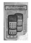
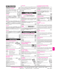
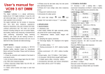
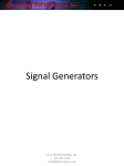
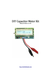
DIGITAL CAPACITANCE METER
OPERATION MANUAL
1.FEATURES
Overload protection: Protected by a 0.2A/250V self- fused. The capacitance will
lead capacitance may be measured by opening the leads at the trips, recording
destroy the meter if the DCV is higher than 60V.
the open circuit value and subtracting that value.
Zero adjust: limit to 20pF
(e) Capacitors, especially electrolytic, often have notoriously wide tolerances.
◇
Easy and correct readout.
3.OPERATION
Do not be surprised if the measured value is greater than the value marked on
◇
High measuring accuracy.
3-1, Pannel description: (see the fig.1)
the capacitor, unless it is a close tolerance type. However, value is seldom
◇
Measurements are possible even under a strong magnetic field.
3-1-1. LCD: display the measuring value, unit and low
drastically below the rated value.
◇
LSI-circuit provides high reliability and durability.
battery indication,
(f) If changing range, measured value will be changed; leakage-voltage
◇
Input overload protection is provided.
3-1-2. POWER switch: turn on/off the power.
◇
LCD display for low power consumption and clear readout even in
3-1-3. Zero adjust knob: zero adjust knob before the
200nF
2uF
20nF
bright ambient light conditions.
2nF
200pF
capacitors will be checked also. Leakage-resistance will be decreased in lower
20uF
200uF
2000uF
20mF
◇
In-line pushbuttons allow one hand operation.
3-1-4. Function knob: to select measuring
◇
Light-weight and compact construction for easy operation.
3-1-5. Input COM: Capacity(Cx)COM
◇
Low battery condition is indicated on the LCD display.
3-1-6. Battery case
range.
3-4.AUTO POWER OFF
measuring of lower than 20nF range
range.
The meter will be into sleeping mode when it stopped work for 20minutes.
Please restart the power if you need to continue to measure.
3-5. MAINTENANCE
Do not try to modify the electric circuit.
3-2. Notice before measuring:
3-5-1. Keep the meter away from water, dust and shock.
2-1.GENERAL SPECIFICATIONS
3-2-1. Observe polarity when connecting polarized capacitors.
3-5-2 Do not store and operate the meter under the condition of high temperature, high
Display
:LCD (Liquid Crystal Display) Max. display 1999.
3-2-2. Discharge completely for any capacitance;
Range
:9 range, whole range value (from 0.1pF to 20mF)
3-2-3. Do not connect any COM with voltage source absolutely, otherwise it will
humidity, combustible, explosive and strong magnetic place.
3-5-3. Wipe the case with a damp cloth and detergent, do not use abrasives and alcohol.
Overload protection
: Display “1”.
2.SPECIFICATIONS
cause damage badly.
Calibrate Adjustment :Have two internal adjustment. One is panel Zero
3-2-4. Do not close (black & red) test leads.
adjustment.
3-2-5. Before removing the battery and fuse compartment cover, ensure that the
:Manual (range:±20pF)
instrument is disconnected with any circuit and the power switch is in the off
:Display“1”.
position.
Sampling Time
:0~5second
3-2-6. zero adjust won’t work when using the external components alligators if
Operating Temp
:0℃ to 40℃.
Zero Adjustment
Over-range dispaly
3-5-4. If do not operate for a long time, should take out the battery to avoid leakage
signal displays, should replace the battery following the steps:
3-5-5. When
3-5-5-1. Take off the holster. (see fig. 2)
3-5-5-2 Unlock the screw and remove the battery case.
3-5-5-3. Take out the old battery and replace the new one. It's better to use alkaline battery
for longer life
3-5-5-4. Fit on the battery case and lock the screw.
3-5-5-5. Fit on the holster as the opposite way (see fig.2)
the capacitance is beyond 20nF.
Operating Humidity
:80% MAX.R.H.
3-3.CAPACITANCE(C) MEASURING PROCEDURE
Battery
:9V (6F22 or the equivalent
3-3-1 Press POWER key, turn on the power.
Battery Life
: alkaline battery: approx.200 hours.
3-3-2 Select the range switch for the maximum expected capacitance.
Zinc-Carbon battery approx. 100 hours
3-3-3 Check "0" indication: If test range is 200pF, 2nF, 20nF, should check "0"
200nF
Typical consumption current: 3~4mA (RANGE: 200pF-200uF)
indication before test.
Standard Accessories: Test alligator clips (red & black)…1 pair.
3-3-4 Observe polarity when connecting polarized capacitors.
Instruction manual………………..1 pc.
3-3-6 Connect the alligator clips to the capacitors leads.
Accuracy is ±(percentage of reading + number of digit) at 23±5℃,<80%RH.
3-3-7 Read the display. The value is direct reading in the electrical unit (pF, nF,
Range
Resolution
Test Frequency
Max indication value
uF,mF) indicated at the selected range switch. If display show “1”, It indicate on
200pF
0.1pF
800Hz
199.9pF
Out-of-Range measurement. If the display indicates one or more leading zeros,
2nF
1pF
800Hz
1.999nF
shift to the next lower range scale to improve the resolution of the measurement.
20nF
10pF
800Hz
19.99nF
200nF
2uF
20uF
100pF
1000pF
0.01uF
800Hz
800Hz
80Hz
199.9nF
1.999uF
19.99uF
200uF
0.1uF
8Hz
199.9uF
(b) A shorted capacitor will read over-range on all ranges. A capacitance with
2000uF
1uF
8Hz
1999uF
low voltage leakage will read over range, or a much higher value than normal.
20mF
10uF
8Hz
19.99mF
Accuracy: range at 200pF~200μF: ±0.5%+1 digit;
range at 2000μF: ±2%+1 digit; range at 20mF: ±2%+2 digit
Excite voltage: 2.8V peak value
2uF
200nF
20uF
20nF
200uF
2000uF
20mF
2nF
200pF
2uF
20uF
200uF
2000uF
20mF
3-3-5.Full discharge any capacitors.
2-2. ELECTRICAL SPECIFICATION
Temperature range for the accuracy guaranteed: 23℃±5℃
20nF
2nF
200pF
NOTE:
(a) If the capacitance value is unmarked, start with the 200pF range and keep
increasing until the over-range indication goes off and a reading is obtained.
An open capacitor will read zero on all ranges.
(c) Measure of very low capacitance should be performed using extremely short
z The specifications are subject to change without totice.
z The content of this manual is regarded as correct, error or omits. Please
contact with factory.
z We herby will not be responsible for the accident and damage caused by
improper operation.
z The function stated for this User Manual cannot be the reason of special
usage.
leads in order to avoid introducing any stray inductance.
(d) When using the optioned test leads, remember that the leads introduce a
measurable capacitance to the measurement. As a first approximation, the test
VC6013