Download Layer 2 Managed Stackable Switches

Transcript
User’s Manual of SGSD-1022 / SGSD-1022P
SGSW-2840 / SGSW-2840P
User’s Manual
SGSD-1022 / SGSD-1022P
8-Port 10/100Base-TX + 2G TP/SFP
SGSW-2840 / SGSW-2840R
24-Port 10/100Base-TX + 4G TP/SFP
SGSW-2840P / SGSW-2840P4
24-Port 10/100 PoE + 4G TP/SFP
Layer 2 Managed Stackable Switches
1
User’s Manual of SGSD-1022 / SGSD-1022P
SGSW-2840 / SGSW-2840P
Trademarks
Copyright © PLANET Technology Corp. 2010.
Contents subject to which revision without prior notice.
PLANET is a registered trademark of PLANET Technology Corp.
All other trademarks belong to their respective owners.
Disclaimer
PLANET Technology does not warrant that the hardware will work properly in all environments and applications, and makes no
warranty and representation, either implied or expressed, with respect to the quality, performance, merchantability, or fitness for
a particular purpose. PLANET has made every effort to ensure that this User's Manual is accurate; PLANET disclaims liability
for any inaccuracies or omissions that may have occurred.
Information in this User's Manual is subject to change without notice and does not represent a commitment on the part of
PLANET. PLANET assumes no responsibility for any inaccuracies that may be contained in this User's Manual. PLANET makes
no commitment to update or keep current the information in this User's Manual, and reserves the right to make improvements to
this User's Manual and/or to the products described in this User's Manual, at any time without notice.
If you find information in this manual that is incorrect, misleading, or incomplete, we would appreciate your comments and
suggestions.
FCC Warning
This equipment has been tested and found to comply with the limits for a Class A digital device, pursuant to Part 15 of the FCC
Rules. These limits are designed to provide reasonable protection against harmful interference when the equipment is operated
in a commercial environment. This equipment generates, uses, and can radiate radio frequency energy and, if not installed and
used in accordance with the Instruction manual, may cause harmful interference to radio communications. Operation of this
equipment in a residential area is likely to cause harmful interference in which case the user will be required to correct the
interference at whose own expense.
CE Mark Warning
This is a Class A product. In a domestic environment, this product may cause radio interference, in which case the user may be
required to take adequate measures.
Energy Saving Note of the Device
This power required device does not support Standby mode operation.
For energy saving, please remove the power cable to disconnect the device from the power circuit.
Without removing power cable, the device will still consuming power from the power source. In the view of Saving the Energy
and reduce the unnecessary power consuming, it is strongly suggested to remove the power connection for the device if this
device is not intended to be active.
WEEE Warning
To avoid the potential effects on the environment and human health as a result of the presence of
hazardous substances in electrical and electronic equipment, end users of electrical and electronic
equipment should understand the meaning of the crossed-out wheeled bin symbol. Do not dispose of
WEEE as unsorted municipal waste and have to collect such WEEE separately.
Revision
PLANET 8 / 24-Port 10/100Mbps with 2 / 4 Gigabit TP / SFP Combo Managed Security Switch User's Manual
FOR MODELS: SGSD-1022 / SGSD-1022P / SGSW-2840 / SGSW-2840R / SGSW-2840P / SGSW-2840P4
REVISION: 1.1 (April.2010)
Part No: EM-SGSD-SGSW (2080-A34050-001)
2
User’s Manual of SGSD-1022 / SGSD-1022P
SGSW-2840 / SGSW-2840P
TABLE OF CONETNTS
1. INTRODUTION .................................................................................................................... 23
1.1 Packet Contents .........................................................................................................................................23
1.2 Product Description ...................................................................................................................................23
1.3 How to Use This Manual ............................................................................................................................25
1.4 Product Features........................................................................................................................................25
1.5 Product Specification ................................................................................................................................28
2. INSTALLATION ................................................................................................................... 31
2.1 Hardware Description ................................................................................................................................31
2.1.1 Switch Front Panel ..............................................................................................................................................31
2.1.2 LED Indications ...................................................................................................................................................32
2.1.3 Switch Rear Panel ...............................................................................................................................................36
2.2 Install the Switch ........................................................................................................................................39
2.2.1 Desktop Installation .............................................................................................................................................39
2.2.2 Rack Mounting.....................................................................................................................................................40
2.2.3 Installing the SFP transceiver ..............................................................................................................................42
3. SWITCH MANAGEMENT .................................................................................................... 44
3.1 Requirements..............................................................................................................................................44
3.2 Management Access Overview .................................................................................................................45
3.3 Administration Console .............................................................................................................................45
3.4 Web Management .......................................................................................................................................47
3.5 SNMP-Based Network Management.........................................................................................................47
3.6 Protocols .....................................................................................................................................................48
3.6.1 Virtual Terminal Protocols ....................................................................................................................................48
3.6.2 SNMP Protocol ....................................................................................................................................................48
3.6.3 Management Architecture....................................................................................................................................48
4. WEB CONFIGURATION ...................................................................................................... 49
4.1 Main WEB PAGE .........................................................................................................................................52
3
User’s Manual of SGSD-1022 / SGSD-1022P
SGSW-2840 / SGSW-2840P
4.2 System.........................................................................................................................................................55
4.2.1 System Information..............................................................................................................................................56
4.2.2 Switch Information ...............................................................................................................................................57
4.2.3 Bridge Extension Configuration ...........................................................................................................................58
4.2.4 IP Configuration ...................................................................................................................................................59
4.2.5 Jumbo Frames.....................................................................................................................................................61
4.2.6 File Management .................................................................................................................................................61
4.2.6.1 Copy Operation.......................................................................................................................................61
4.2.6.2 Delete .....................................................................................................................................................67
4.2.6.3 Set Startup ..............................................................................................................................................67
4.2.7 Line......................................................................................................................................................................69
4.2.7.1 Console Port Settings................................................................................................................................69
4.2.7.2 Telnet Settings ...........................................................................................................................................71
4.2.8 Log ......................................................................................................................................................................72
4.2.8.1 System Log Configuration .........................................................................................................................72
4.2.8.2 Remote Log Configuration.........................................................................................................................74
4.2.8.3 Displaying Log Messages..........................................................................................................................75
4.2.8.4 SMTP E-Mail Alert .....................................................................................................................................76
4.2.9 UPNP...................................................................................................................................................................78
UPnP Configuration...............................................................................................................................................78
4.2.10 Reset .................................................................................................................................................................79
4.2.11 SNTP .................................................................................................................................................................80
4.2.11.1 SNTP Configuration .................................................................................................................................80
4.2.11.2 Clock Time Zone......................................................................................................................................81
4.2.12 LLDP..................................................................................................................................................................82
4.2.12.1 LLDP Configuration .................................................................................................................................82
4.2.12.2 LLDP Port Configuration..........................................................................................................................84
4.2.12.3 LLDP Trunk Configuration .......................................................................................................................87
4.2.12.4 LLDP Local Device Information ...............................................................................................................90
4.2.12.5 Remote Port Information .........................................................................................................................92
4.2.12.6 LLDP Remote Information Detail .............................................................................................................93
4.2.12.7 LLDP Device Statistics ............................................................................................................................95
4.2.12.8 LLDP Device Statistics Details.................................................................................................................96
4.3 Simple Network Management Protocol....................................................................................................97
4.3.1 SNMP Agent Status .............................................................................................................................................98
4.3.2 SNMP Configuration ............................................................................................................................................98
4.3.2.1 SNMP Community .....................................................................................................................................98
4.3.2.2 SNMP Trap Management ..........................................................................................................................99
4.3.3 SNMPv3 ............................................................................................................................................................102
4.3.3.1 SNMPv3 Engine ID..................................................................................................................................102
4
User’s Manual of SGSD-1022 / SGSD-1022P
SGSW-2840 / SGSW-2840P
4.3.3.2 SNMPv3 Remote Engine ID ....................................................................................................................103
4.3.3.3 SNMPv3 Users ........................................................................................................................................104
4.3.3.4 SNMPv3 Remote Users ..........................................................................................................................107
4.3.3.5 SNMPv3 Groups......................................................................................................................................109
4.3.3.6 SNMPv3 View.......................................................................................................................................... 112
4.4 Port Management .....................................................................................................................................114
4.4.1 Port Information ................................................................................................................................................. 114
4.4.2 Port Configuration.............................................................................................................................................. 116
4.4.3 Port Broadcast Control ...................................................................................................................................... 118
4.4.4 Port Mirroring.....................................................................................................................................................120
4.4.4.1 Mirror Port Configuration .........................................................................................................................120
4.4.5 Rate Limit ..........................................................................................................................................................123
4.4.5.1 Input Rate Limit Port Configuration..........................................................................................................123
4.4.5.2 Output Rate Limit Port Configuration.......................................................................................................124
4.4.6 Port Statistics.....................................................................................................................................................125
4.5 Link Aggregation ......................................................................................................................................130
4.5.1 Trunk Information...............................................................................................................................................131
4.5.2 Trunk Configuration ...........................................................................................................................................131
4.5.3 Trunk Broadcast Control ....................................................................................................................................133
4.5.4 Trunk Membership .............................................................................................................................................134
4.5.5 LACP .................................................................................................................................................................137
4.5.5.1 LACP Configuration.................................................................................................................................138
4.5.5.2 LACP Aggregation Port ...........................................................................................................................139
4.5.5.3 Displaying LACP Port Counters...............................................................................................................142
4.5.5.4 Displaying LACP Settings and Status for the Local Side .........................................................................142
4.5.5.5 Displaying LACP Status for the Remote Side ..........................................................................................144
4.6 Address Table ...........................................................................................................................................146
4.6.1 Static Addresses ................................................................................................................................................146
4.6.2 Dynamic Addresses ...........................................................................................................................................147
4.6.3 Address Aging....................................................................................................................................................149
4.7 Spanning Tree...........................................................................................................................................150
4.7.1 STA....................................................................................................................................................................158
4.7.1.1 Spanning Tree Information ......................................................................................................................158
4.7.1.2 STA Configuration....................................................................................................................................160
4.7.1.3 STA Port Information ...............................................................................................................................164
4.7.1.4 STA Port Configuration ............................................................................................................................166
4.7.2 MSTP.................................................................................................................................................................169
4.7.2.1 Configuring Multiple Spanning Trees .......................................................................................................169
5
User’s Manual of SGSD-1022 / SGSD-1022P
SGSW-2840 / SGSW-2840P
4.7.2.2 Displaying Interface Settings for MSTP ...................................................................................................170
4.7.2.3 MSTP Port Configuration.........................................................................................................................171
4.8 VLAN Configuration .................................................................................................................................173
4.8.1 IEEE 802.1Q VLANs .........................................................................................................................................174
4.8.1.1 VLAN Basic Information ..........................................................................................................................178
4.8.1.2 GVRP Status ...........................................................................................................................................179
4.8.1.3 VLAN Current Table.................................................................................................................................180
4.8.1.4 VLAN Static List.......................................................................................................................................181
4.8.1.5 VLAN Static Table....................................................................................................................................182
4.8.1.6 Static Membership by Port.......................................................................................................................185
4.8.1.7 VLAN Port Configuration .........................................................................................................................186
4.8.2 Q-in-Q VLAN .....................................................................................................................................................189
4.8.2.1 802.1Q Tunnel Configuration...................................................................................................................192
4.8.2.2 802.1Q Tunnel Port Configuration ...........................................................................................................193
4.8.3 Private VLAN .....................................................................................................................................................195
4.8.3.1 Private VLAN Information ........................................................................................................................197
4.8.3.2 Private VLAN Configuration.....................................................................................................................198
4.8.3.3 Private VLAN Association........................................................................................................................199
4.8.3.4 Private VLAN Port Information ................................................................................................................200
4.8.3.5 Private VLAN Port Configuration .............................................................................................................201
4.8.4 Protocol VLAN ...................................................................................................................................................203
4.8.4.1 Protocol VLAN Configuration...................................................................................................................204
4.8.4.2 Protocol VLAN Port Configuration ...........................................................................................................205
4.9 Multicast ....................................................................................................................................................207
4.9.1.1 IGMP Configuration .................................................................................................................................212
4.9.1.2 IGMP Immediate Leave ...........................................................................................................................214
4.9.1.3 Multicast Router Port Information ............................................................................................................215
4.9.1.4 Static Multicast Router Port Configuration ...............................................................................................216
4.9.1.5 IP Multicast Registration Table ................................................................................................................217
4.9.1.6 IGMP Member Port Table ........................................................................................................................218
4.9.2 IGMP Filter and Throttling..................................................................................................................................220
4.9.2.1 IGMP Filter Profile Configuration .............................................................................................................220
4.9.2.2 IGMP Filter Profile Configuration .............................................................................................................221
4.9.2.3 IGMP Filter / Throttling Port Configuration...............................................................................................222
4.9.3 Multicast VLAN Registration (MVR)...................................................................................................................224
4.9.3.1 MVR Configuration ..................................................................................................................................225
4.9.3.2 MVR Port Configuration...........................................................................................................................226
4.9.3.3 MVR Port Information ..............................................................................................................................228
4.9.3.4 MVR Group Member Configuration .........................................................................................................228
6
User’s Manual of SGSD-1022 / SGSD-1022P
SGSW-2840 / SGSW-2840P
4.9.3.5 MVR Group IP Information ......................................................................................................................230
4.10 Quality of Service ...................................................................................................................................231
4.10.1 Priority .............................................................................................................................................................232
4.10.1.1 Port Priority Configuration .....................................................................................................................233
4.10.1.2 Traffic Classes .......................................................................................................................................234
4.10.1.3 Queue Mode..........................................................................................................................................236
4.10.1.4 Queue Scheduling .................................................................................................................................237
4.10.2 Layer 3/4 Priority Settings................................................................................................................................238
4.10.2.1 Mapping Layer 3/4 Priorities to CoS Values ..........................................................................................238
4.10.2.2 IP DSCP Priority Status .........................................................................................................................238
4.10.2.3 IP DSCP Priority ....................................................................................................................................239
4.10.2.4 Mapping IP Precedence Priority ............................................................................................................240
4.10.2.5 IP Precedence Priority Status ................................................................................................................240
4.10.2.6 IP Precedence Priority ...........................................................................................................................241
4.10.2.7 Mapping IP TOS Priority ........................................................................................................................241
4.10.2.8 IP TOS Priority Status............................................................................................................................242
4.10.2.9 IP TOS Priority.......................................................................................................................................243
4.10.2.10 Mapping IP Port Priority.......................................................................................................................243
4.10.2.11 IP Port Priority Status...........................................................................................................................244
4.10.2.12 IP Port Priority .....................................................................................................................................245
4.10.2.13 Mapping CoS Values to ACLs..............................................................................................................245
4.10.2.14 ACL CoS Priority..................................................................................................................................246
4.10.3 DiffServ............................................................................................................................................................247
4.10.3.1 Configuring a DiffServ Class Map..........................................................................................................248
4.10.3.2 Policy Map.............................................................................................................................................251
4.10.3.3 Service Policy ........................................................................................................................................255
4.10.4 Voice VLANs....................................................................................................................................................256
4.10.4.1 VoIP Traffic Configuration ......................................................................................................................256
4.10.4.2 VoIP Port Configuration .........................................................................................................................257
4.10.4.3 Telephony OUI Configuration.................................................................................................................259
4.11 Security....................................................................................................................................................260
4.11.1 User Authentication..........................................................................................................................................260
4.11.1 Configuring User Accounts ..............................................................................................................................260
4.11.2 Configuring Local / Remote Logon Authentication ...........................................................................................262
4.11.3 RADIUS Settings .............................................................................................................................................264
4.11.4 TACACS Settings.............................................................................................................................................265
4.11.5 AAA Authorization and Accounting ...................................................................................................................266
4.11.5.1 RADIUS Group Settings ........................................................................................................................267
4.11.5.2 AAA TACACS+ Group Settings..............................................................................................................267
7
User’s Manual of SGSD-1022 / SGSD-1022P
SGSW-2840 / SGSW-2840P
4.11.5.3 AAA Accounting Settings .......................................................................................................................268
4.11.5.4 AAA Accounting Update.........................................................................................................................269
4.11.5.5 AAA Accounting 802.1X Port Settings....................................................................................................270
4.11.5.6 AAA Accounting Exec Command Privileges ..........................................................................................271
4.11.5.7 AAA Accounting EXEC Settings.............................................................................................................272
4.11.5.8 AAA Accounting Summary .....................................................................................................................273
4.11.5.9 AAA Accounting Statistics Summary ......................................................................................................274
4.11.5.10 Authorization Settings ..........................................................................................................................274
4.11.5.11 AAA Authorization EXEC Settings ........................................................................................................275
4.11.5.12 AAA Authorization Summary ................................................................................................................275
4.11.6 HTTPS Setting .................................................................................................................................................276
4.11.7 SSH .................................................................................................................................................................278
4.11.7.1 Configure Secure Shell ..........................................................................................................................278
4.11.7.2 SSH Server Settings..............................................................................................................................280
4.11.7.3 SSH Host-Key Settings..........................................................................................................................281
4.11.8 802.1X Port Authentication ..............................................................................................................................284
4.11.8.1 Understanding IEEE 802.1X Port-Based Authentication........................................................................285
4.11.8.2 Displaying 802.1X Information ...............................................................................................................288
4.11.8.3 802.1X Configuration .............................................................................................................................288
4.11.8.4 802.1X Port Configuration......................................................................................................................289
4.11.8.5 Displaying 802.1X Statistics...................................................................................................................291
4.11.8.7 Windows Platform RADIUS Server Configuration..................................................................................292
4.11.8.8 802.1X Client Configuration ...................................................................................................................294
4.11.9 Client Security..................................................................................................................................................297
4.11.10 Port Security ..................................................................................................................................................298
4.11.11 Web Authentication ........................................................................................................................................301
4.11.11.1 Web Authentication Configuration ........................................................................................................302
4.11.11.2 Web Authentication Port Configuration ................................................................................................303
4.11.11.3 Web Authentication Port Information....................................................................................................303
4.11.11.4 Re-Authentication ................................................................................................................................304
4.11.12 Network Access (MAC Address Authentication).............................................................................................306
4.11.12.1 Network Access Configuration .............................................................................................................307
4.11.12.2 Network Access Port Configuration .....................................................................................................307
4.11.12.3 Network Access MAC Address Information..........................................................................................309
4.11.13 Access Control Lists....................................................................................................................................... 311
4.11.13.1 ACL Configuration................................................................................................................................ 311
4.11.13.2 Configure a Standard ACL ...................................................................................................................313
4.11.13.3 Extended ACL......................................................................................................................................314
4.11.13.4 MAC ACL .............................................................................................................................................316
4.11.13.5 ACL Port Binding..................................................................................................................................319
8
User’s Manual of SGSD-1022 / SGSD-1022P
SGSW-2840 / SGSW-2840P
4.11.14 IP Filter ..........................................................................................................................................................321
4.11.14.1 Web IP Filter ........................................................................................................................................321
4.11.14.2 SNMP IP Filter .....................................................................................................................................322
4.11.14.3 Telnet IP Filter ......................................................................................................................................323
4.11.15 DHCP Snooping.............................................................................................................................................325
4.11.15.1 DHCP Snooping Configuration ............................................................................................................326
4.11.15.2 DHCP Snooping VLAN Configuration ..................................................................................................326
4.11.15.3 Information Option Configuration .........................................................................................................327
4.11.15.4 DHCP Snooping Port Configuration.....................................................................................................329
4.11.16 IP Source Guard ............................................................................................................................................330
4.11.16.1 Port Configuration................................................................................................................................330
4.11.16.2 Static Configuration..............................................................................................................................332
4.11.16.3 Dynamic Information............................................................................................................................333
4.12 Cluster .....................................................................................................................................................335
4.12.1 Cluster Configuration .......................................................................................................................................335
4.12.2 Cluster Member Configuration.........................................................................................................................337
4.12.3 Cluster Member Information ............................................................................................................................337
4.12.4 Cluster Candidate Information .........................................................................................................................338
4.13 Power Over Ethernet (SGSD-1022P / SGSW-2840P / SGSW-2840P4) ...............................................340
4.13.1 Power over Ethernet Powered Device .............................................................................................................340
4.13.2 Power Management: .......................................................................................................................................341
5. COMMAND LINE INTERFACE.......................................................................................... 344
5.1 Using the Command Line Interface........................................................................................................344
5.1.1 Accessing the CLI ..............................................................................................................................................344
5.1.2 Console Connection ..........................................................................................................................................344
5.1.3 Telnet Connection ..............................................................................................................................................344
5.2 Entering Commands ................................................................................................................................346
5.2.1 Keywords and Arguments..................................................................................................................................346
5.2.2 Minimum Abbreviation .......................................................................................................................................346
5.2.3 Command Completion .......................................................................................................................................346
5.2.4 Getting Help on Commands ..............................................................................................................................346
5.2.5 Showing Commands .........................................................................................................................................347
5.2.6 Partial Keyword Lookup.....................................................................................................................................349
5.2.7 Negating the Effect of Commands .....................................................................................................................349
5.2.8 Using Command History....................................................................................................................................349
5.2.9 Understanding Command Modes ......................................................................................................................349
5.2.10 Exec Commands .............................................................................................................................................350
9
User’s Manual of SGSD-1022 / SGSD-1022P
SGSW-2840 / SGSW-2840P
5.2.11 Configuration Commands ................................................................................................................................351
5.2.12 Command Line Processing..............................................................................................................................352
5.3 Command Groups ....................................................................................................................................353
5.4 General Commands .................................................................................................................................354
enable..................................................................................................................................................................354
disable .................................................................................................................................................................355
configure..............................................................................................................................................................356
show history ........................................................................................................................................................356
reload ..................................................................................................................................................................357
prompt .................................................................................................................................................................358
end ......................................................................................................................................................................358
exit.......................................................................................................................................................................358
quit ......................................................................................................................................................................359
5.5 System Management Commands...........................................................................................................360
5.5.1 Device Designation Commands ........................................................................................................................360
hostname.............................................................................................................................................................360
5.5.2 Banner Information Commands.........................................................................................................................361
banner configure .................................................................................................................................................361
banner configure company ..................................................................................................................................363
banner configure dc-power-info...........................................................................................................................363
banner configure department ..............................................................................................................................364
banner configure equipment-info.........................................................................................................................364
banner configure equipment-location ..................................................................................................................365
banner configure ip-lan........................................................................................................................................366
banner configure lp-number ................................................................................................................................366
banner configure manager-info ...........................................................................................................................367
banner configure mux..........................................................................................................................................368
banner configure note .........................................................................................................................................368
show banner........................................................................................................................................................369
5.5.3 System Status Commands ................................................................................................................................370
show startup-config .............................................................................................................................................370
show running-config ............................................................................................................................................372
show system........................................................................................................................................................374
show users ..........................................................................................................................................................375
show version .......................................................................................................................................................376
5.5.4 Frame Size Commands .....................................................................................................................................377
jumbo frame ........................................................................................................................................................377
5.5.5 File Management Commands............................................................................................................................378
copy.....................................................................................................................................................................378
10
User’s Manual of SGSD-1022 / SGSD-1022P
SGSW-2840 / SGSW-2840P
delete ..................................................................................................................................................................381
dir ........................................................................................................................................................................382
whichboot ............................................................................................................................................................383
boot system .........................................................................................................................................................383
5.6 Line Commands .......................................................................................................................................384
line.......................................................................................................................................................................385
login.....................................................................................................................................................................385
password .............................................................................................................................................................386
timeout login response ........................................................................................................................................387
exec-timeout........................................................................................................................................................388
password-thresh ..................................................................................................................................................388
silent-time ............................................................................................................................................................389
databits................................................................................................................................................................389
parity....................................................................................................................................................................390
speed ..................................................................................................................................................................391
stopbits ................................................................................................................................................................391
disconnect ...........................................................................................................................................................392
show line .............................................................................................................................................................392
5.7 Event Logging Commands......................................................................................................................393
logging on............................................................................................................................................................393
logging history .....................................................................................................................................................394
logging host .........................................................................................................................................................395
logging facility......................................................................................................................................................396
logging trap..........................................................................................................................................................396
clear log...............................................................................................................................................................397
show logging .......................................................................................................................................................397
show log ..............................................................................................................................................................399
5.8 SMTP Alert Commands............................................................................................................................400
logging sendmail host..........................................................................................................................................400
logging sendmail level .........................................................................................................................................401
logging sendmail source-email ............................................................................................................................401
logging sendmail destination-email .....................................................................................................................402
logging sendmail .................................................................................................................................................402
show logging sendmail ........................................................................................................................................403
5.9 Time Commands.......................................................................................................................................403
sntp client ............................................................................................................................................................404
sntp server...........................................................................................................................................................405
sntp poll ...............................................................................................................................................................405
11
User’s Manual of SGSD-1022 / SGSD-1022P
SGSW-2840 / SGSW-2840P
show sntp ............................................................................................................................................................406
clock timezone.....................................................................................................................................................406
calendar set.........................................................................................................................................................407
show calendar .....................................................................................................................................................408
5.10 Switch Cluster Commands....................................................................................................................408
cluster..................................................................................................................................................................409
cluster commander ..............................................................................................................................................409
cluster ip-pool ......................................................................................................................................................410
cluster member....................................................................................................................................................410
rcommand ........................................................................................................................................................... 411
show cluster ........................................................................................................................................................ 411
show cluster members.........................................................................................................................................412
show cluster candidates ......................................................................................................................................412
5.11 SNMP Commands...................................................................................................................................413
snmp-server ........................................................................................................................................................414
show snmp ..........................................................................................................................................................414
snmp-server community ......................................................................................................................................415
snmp-server contact ............................................................................................................................................416
Related Commands.............................................................................................................................................416
snmp-server host.................................................................................................................................................417
snmp-server enable traps....................................................................................................................................419
snmp-server engine-id.........................................................................................................................................420
show snmp engine-id ..........................................................................................................................................420
snmp-server view ................................................................................................................................................421
show snmp view ..................................................................................................................................................422
snmp-server group ..............................................................................................................................................423
show snmp group ................................................................................................................................................424
snmp-server user ................................................................................................................................................425
show snmp user ..................................................................................................................................................427
5.12 Authentication Commands....................................................................................................................428
5.12.1 User Account Commands ................................................................................................................................428
username ............................................................................................................................................................428
enable password .................................................................................................................................................429
5.12.2 Authentication Sequence .................................................................................................................................430
authentication login .............................................................................................................................................431
authentication enable ..........................................................................................................................................431
5.12.3 RADIUS Client.................................................................................................................................................432
radius-server host................................................................................................................................................433
radius-server auth-port ........................................................................................................................................434
12
User’s Manual of SGSD-1022 / SGSD-1022P
SGSW-2840 / SGSW-2840P
radius-server acct-port.........................................................................................................................................434
radius-server key.................................................................................................................................................434
radius-server retransmit.......................................................................................................................................435
radius-server timeout...........................................................................................................................................435
show radius-server ..............................................................................................................................................436
5.13.4 TACACS+ Client ..............................................................................................................................................437
tacacs-server host ...............................................................................................................................................437
tacacs-server port................................................................................................................................................438
tacacs-server key ................................................................................................................................................438
tacacs-server retransmit ......................................................................................................................................439
tacacs-server timeout ..........................................................................................................................................439
show tacacs-server..............................................................................................................................................440
5.12.5 AAA Commands ..............................................................................................................................................441
aaa group server .................................................................................................................................................441
server ..................................................................................................................................................................442
aaa accounting dot1x ..........................................................................................................................................442
aaa accounting exec ...........................................................................................................................................443
aaa accounting commands..................................................................................................................................444
aaa accounting update ........................................................................................................................................445
accounting dot1x .................................................................................................................................................445
accounting exec ..................................................................................................................................................446
accounting commands ........................................................................................................................................446
aaa authorization exec ........................................................................................................................................447
authorization exec ...............................................................................................................................................448
show accounting..................................................................................................................................................448
5.12.6 Web Server Commands ..................................................................................................................................450
ip http port ...........................................................................................................................................................450
ip http server........................................................................................................................................................450
ip http secure-server............................................................................................................................................451
ip http secure-port ...............................................................................................................................................452
5.12.7 Telnet Server Commands ................................................................................................................................453
ip telnet server.....................................................................................................................................................453
5.12.8 Secure Shell Commands .................................................................................................................................454
ip ssh server ........................................................................................................................................................456
ip ssh timeout ......................................................................................................................................................457
ip ssh authentication-retries.................................................................................................................................458
ip ssh server-key size..........................................................................................................................................458
delete public-key .................................................................................................................................................459
ip ssh crypto host-key generate...........................................................................................................................459
ip ssh crypto zeroize............................................................................................................................................460
13
User’s Manual of SGSD-1022 / SGSD-1022P
SGSW-2840 / SGSW-2840P
ip ssh save host-key............................................................................................................................................461
show ip ssh..........................................................................................................................................................461
show ssh .............................................................................................................................................................462
show public-key...................................................................................................................................................463
5.12.9 802.1X Port Authentication ..............................................................................................................................464
dot1x system-auth-control ...................................................................................................................................465
dot1x default........................................................................................................................................................465
dot1x max-req .....................................................................................................................................................465
dot1x port-control ................................................................................................................................................466
dot1x operation-mode .........................................................................................................................................466
dot1x re-authenticate...........................................................................................................................................467
dot1x re-authentication ........................................................................................................................................468
dot1x timeout quiet-period ...................................................................................................................................468
dot1x timeout re-authperiod.................................................................................................................................469
dot1x timeout tx-period ........................................................................................................................................469
dot1x intrusion-action ..........................................................................................................................................470
show dot1x ..........................................................................................................................................................471
5.12.10 Management IP Filter Commands .................................................................................................................473
management .......................................................................................................................................................473
show management ..............................................................................................................................................474
5.13 Client Security Commands....................................................................................................................475
5.13.1 Port Security Commands.................................................................................................................................476
port security.........................................................................................................................................................476
5.13.2 Network Access (MAC Address Authentication) ..............................................................................................477
network-access mode .........................................................................................................................................478
network-access max-mac-count..........................................................................................................................479
mac-authentication intrusion-action .....................................................................................................................479
mac-authentication max-mac-count ....................................................................................................................480
network-access dynamic-vlan .............................................................................................................................480
network-access guest-vlan ..................................................................................................................................481
mac-authentication reauth-time ...........................................................................................................................482
clear network-access...........................................................................................................................................482
show network-access ..........................................................................................................................................483
show network-access mac-address-table............................................................................................................484
5.13.3 Web Authentication..........................................................................................................................................485
web-auth login-attempts ......................................................................................................................................485
web-auth quiet-period..........................................................................................................................................486
web-auth session-timeout....................................................................................................................................486
web-auth system-auth-control .............................................................................................................................487
web-auth..............................................................................................................................................................487
14
User’s Manual of SGSD-1022 / SGSD-1022P
SGSW-2840 / SGSW-2840P
web-auth re-authenticate (Port)...........................................................................................................................488
web-auth re-authenticate (IP) ..............................................................................................................................488
show web-auth ....................................................................................................................................................489
show web-auth interface......................................................................................................................................489
show web-auth summary.....................................................................................................................................490
5.13.4 DHCP Snooping Commands ...........................................................................................................................491
ip dhcp snooping .................................................................................................................................................491
ip dhcp snooping vlan..........................................................................................................................................493
ip dhcp snooping trust .........................................................................................................................................493
ip dhcp snooping verify mac-address ..................................................................................................................494
ip dhcp snooping information option....................................................................................................................495
ip dhcp snooping information policy ....................................................................................................................496
show ip dhcp snooping ........................................................................................................................................496
show ip dhcp snooping binding ...........................................................................................................................497
5.13.5 IP Source Guard Commands...........................................................................................................................497
ip source-guard ...................................................................................................................................................498
ip source-guard binding .......................................................................................................................................499
show ip source-guard ..........................................................................................................................................500
show ip source-guard binding..............................................................................................................................501
5.14 Access Control List Commands ...........................................................................................................501
5.14.1 IP ACLs............................................................................................................................................................502
access-list ip........................................................................................................................................................502
permit, deny (Standard ACL) ...............................................................................................................................503
permit, deny (Extended ACL) ..............................................................................................................................504
show ip access-list ..............................................................................................................................................506
ip access-group ...................................................................................................................................................507
show ip access-group..........................................................................................................................................507
map access-list ip................................................................................................................................................508
show map access-list ip.......................................................................................................................................509
5.14.2 MAC ACLs .......................................................................................................................................................509
access-list mac....................................................................................................................................................510
permit, deny (MAC ACL)......................................................................................................................................510
show mac access-list ..........................................................................................................................................512
mac access-group ...............................................................................................................................................512
show mac access-group......................................................................................................................................513
map access-list mac............................................................................................................................................513
show map access-list mac...................................................................................................................................514
5.14.3 ACL Information ...............................................................................................................................................515
show access-list ..................................................................................................................................................515
show access-group .............................................................................................................................................516
15
User’s Manual of SGSD-1022 / SGSD-1022P
SGSW-2840 / SGSW-2840P
5.15 Interface Commands..............................................................................................................................516
interface...............................................................................................................................................................517
description ...........................................................................................................................................................517
speed-duplex.......................................................................................................................................................518
negotiation...........................................................................................................................................................519
capabilities...........................................................................................................................................................520
flowcontrol ...........................................................................................................................................................521
shutdown .............................................................................................................................................................522
broadcast byte-rate .............................................................................................................................................522
switchport broadcast ...........................................................................................................................................523
clear counters......................................................................................................................................................524
show interfaces status .........................................................................................................................................524
show interfaces counters.....................................................................................................................................525
show interfaces switchport ..................................................................................................................................527
5.16 Link Aggregation Commands ...............................................................................................................529
channel-group .....................................................................................................................................................530
lacp......................................................................................................................................................................530
lacp system-priority .............................................................................................................................................532
lacp admin-key (Ethernet Interface) ....................................................................................................................533
lacp admin-key (Port Channel) ............................................................................................................................534
lacp port-priority...................................................................................................................................................534
show lacp ............................................................................................................................................................535
5.17 Mirror Port Commands ..........................................................................................................................540
port monitor .........................................................................................................................................................540
show port monitor................................................................................................................................................541
5.18 Rate Limit Commands ...........................................................................................................................541
rate-limit...............................................................................................................................................................542
5.19 Address Table Commands ....................................................................................................................542
mac-address-table static .....................................................................................................................................543
clear mac-address-table dynamic........................................................................................................................544
show mac-address-table .....................................................................................................................................544
mac-address-table aging-time .............................................................................................................................545
show mac-address-table aging-time....................................................................................................................546
5.20 Spanning Tree Commands ....................................................................................................................546
spanning-tree ......................................................................................................................................................547
spanning-tree mode.............................................................................................................................................548
spanning-tree forward-time..................................................................................................................................549
spanning-tree hello-time ......................................................................................................................................549
16
User’s Manual of SGSD-1022 / SGSD-1022P
SGSW-2840 / SGSW-2840P
spanning-tree max-age........................................................................................................................................550
spanning-tree priority...........................................................................................................................................551
spanning-tree pathcost method ...........................................................................................................................551
spanning-tree transmission-limit ..........................................................................................................................552
spanning-tree mst-configuration ..........................................................................................................................552
mst vlan ...............................................................................................................................................................553
mst priority...........................................................................................................................................................554
name ...................................................................................................................................................................554
revision ................................................................................................................................................................555
max-hops.............................................................................................................................................................556
spanning-tree spanning-disabled.........................................................................................................................556
spanning-tree cost ...............................................................................................................................................557
spanning-tree port-priority ...................................................................................................................................558
spanning-tree edge-port ......................................................................................................................................559
spanning-tree portfast..........................................................................................................................................559
spanning-tree link-type ........................................................................................................................................560
spanning-tree mst cost ........................................................................................................................................561
spanning-tree mst port-priority.............................................................................................................................562
spanning-tree protocol-migration .........................................................................................................................563
show spanning-tree .............................................................................................................................................563
show spanning-tree mst configuration .................................................................................................................565
5.21 VLAN Commands ...................................................................................................................................567
5.21.1 GVRP and Bridge Extension Commands ........................................................................................................567
bridge-ext gvrp ....................................................................................................................................................568
show bridge-ext ...................................................................................................................................................568
switchport gvrp ....................................................................................................................................................569
show gvrp configuration.......................................................................................................................................569
garp timer ............................................................................................................................................................570
show garp timer...................................................................................................................................................571
5.21.2 Editing VLAN Groups.......................................................................................................................................572
vlan database ......................................................................................................................................................572
vlan......................................................................................................................................................................572
5.21.3 Configuring VLAN Interfaces ...........................................................................................................................573
interface vlan .......................................................................................................................................................574
switchport mode ..................................................................................................................................................574
switchport acceptable-frame-types ......................................................................................................................575
switchport ingress-filtering ...................................................................................................................................576
switchport native vlan ..........................................................................................................................................577
switchport allowed vlan........................................................................................................................................577
switchport forbidden vlan.....................................................................................................................................578
17
User’s Manual of SGSD-1022 / SGSD-1022P
SGSW-2840 / SGSW-2840P
5.21.4 Displaying VLAN Information...........................................................................................................................579
show vlan ............................................................................................................................................................579
5.21.5 Configuring IEEE 802.1Q Tunneling ................................................................................................................581
dot1q-tunnel system-tunnel-control .....................................................................................................................582
switchport dot1q-tunnel mode .............................................................................................................................582
switchport dot1q-tunnel tpid.................................................................................................................................583
show dot1q-tunnel ...............................................................................................................................................584
5.21.6 Configuring Private VLANs ..............................................................................................................................585
private-vlan..........................................................................................................................................................586
private vlan association .......................................................................................................................................587
switchport mode private-vlan...............................................................................................................................587
switchport private-vlan host-association ..............................................................................................................588
switchport private-vlan isolated ...........................................................................................................................589
switchport private-vlan mapping ..........................................................................................................................589
show private-vlan ................................................................................................................................................590
5.21.7 Configuring Protocol-based VLANs .................................................................................................................591
protocol-vlan protocol-group (Configuring Groups) .............................................................................................591
protocol-vlan protocol-group (Configuring Interfaces) .........................................................................................592
show protocol-vlan protocol-group ......................................................................................................................593
show interfaces protocol-group ...........................................................................................................................594
5.21.8 Configuring Voice VLANs ................................................................................................................................595
voice vlan ............................................................................................................................................................595
voice vlan aging...................................................................................................................................................596
voice vlan mac-address.......................................................................................................................................596
switchport voice vlan ...........................................................................................................................................597
switchport voice vlan rule ....................................................................................................................................598
switchport voice vlan security ..............................................................................................................................599
switchport voice vlan priority................................................................................................................................599
show voice vlan ...................................................................................................................................................600
5.22 LLDP Commands....................................................................................................................................601
lldp.......................................................................................................................................................................603
lldp holdtime-multiplier.........................................................................................................................................603
lldp medFastStartCount .......................................................................................................................................604
lldp notification-interval ........................................................................................................................................604
lldp refresh-interval ..............................................................................................................................................605
lldp reinit-delay ....................................................................................................................................................605
lldp tx-delay .........................................................................................................................................................606
lldp admin-status .................................................................................................................................................607
lldp notification.....................................................................................................................................................607
lldp mednotification..............................................................................................................................................608
18
User’s Manual of SGSD-1022 / SGSD-1022P
SGSW-2840 / SGSW-2840P
lldp basic-tlv management-ip-address .................................................................................................................608
lldp basic-tlv port-description ...............................................................................................................................609
lldp basic-tlv system-capabilities..........................................................................................................................610
lldp basic-tlv system-description..........................................................................................................................610
lldp basic-tlv system-name .................................................................................................................................. 611
lldp dot1-tlv proto-ident ........................................................................................................................................ 611
lldp dot1-tlv proto-vid ...........................................................................................................................................612
lldp dot1-tlv pvid ..................................................................................................................................................612
lldp dot1-tlv vlan-name ........................................................................................................................................613
lldp dot3-tlv link-agg.............................................................................................................................................613
lldp dot3-tlv mac-phy ...........................................................................................................................................614
lldp dot3-tlv max-frame ........................................................................................................................................614
lldp dot3-tlv poe ...................................................................................................................................................615
lldp medtlv extpoe................................................................................................................................................615
lldp medtlv inventory............................................................................................................................................616
lldp medtlv location ..............................................................................................................................................617
lldp medtlv med-cap ............................................................................................................................................617
lldp medtlv network-policy ...................................................................................................................................618
show lldp config...................................................................................................................................................618
show lldp info local-device...................................................................................................................................620
show lldp info remote-device ...............................................................................................................................621
show lldp info statistics ........................................................................................................................................621
5.23 Class of Service Commands .................................................................................................................623
5.23.1 Priority Commands (Layer 2)...........................................................................................................................623
queue mode ........................................................................................................................................................623
switchport priority default.....................................................................................................................................624
queue bandwidth .................................................................................................................................................625
queue cos-map....................................................................................................................................................626
show queue mode ...............................................................................................................................................627
show queue bandwidth........................................................................................................................................627
show queue cos-map ..........................................................................................................................................628
5.23.2 Priority Commands (Layer 3 and 4) .................................................................................................................629
map ip dscp .........................................................................................................................................................629
map ip port ..........................................................................................................................................................630
map ip precedence ..............................................................................................................................................631
map ip tos............................................................................................................................................................632
map access-list ip................................................................................................................................................633
map access-list mac............................................................................................................................................633
show map ip dscp................................................................................................................................................634
show map ip port .................................................................................................................................................634
19
User’s Manual of SGSD-1022 / SGSD-1022P
SGSW-2840 / SGSW-2840P
show map ip precedence.....................................................................................................................................635
show map ip tos ..................................................................................................................................................636
show map access-list ..........................................................................................................................................637
5.24 Quality of Service Commands ..............................................................................................................637
class-map ............................................................................................................................................................638
match...................................................................................................................................................................639
policy-map ...........................................................................................................................................................640
class ....................................................................................................................................................................640
set .......................................................................................................................................................................641
police ...................................................................................................................................................................642
service-policy.......................................................................................................................................................643
show class-map...................................................................................................................................................644
show policy-map..................................................................................................................................................644
show policy-map interface ...................................................................................................................................645
5.25 Multicast Filtering Commands..............................................................................................................646
5.25.1 IGMP Snooping Commands ............................................................................................................................646
ip igmp snooping .................................................................................................................................................646
ip igmp snooping vlan static ................................................................................................................................647
ip igmp snooping version.....................................................................................................................................647
ip igmp snooping immediate-leave ......................................................................................................................649
show ip igmp snooping ........................................................................................................................................649
show mac-address-table multicast ......................................................................................................................650
5.25.2 IGMP Query Commands (Layer 2) ..................................................................................................................651
ip igmp snooping querier .....................................................................................................................................651
ip igmp snooping query-count .............................................................................................................................651
ip igmp snooping query-interval...........................................................................................................................652
ip igmp snooping query-max-response-time........................................................................................................653
5.25.3 Static Multicast Routing Commands ................................................................................................................654
ip igmp snooping vlan mrouter ............................................................................................................................654
show ip igmp snooping mrouter...........................................................................................................................655
5.25.4 IGMP Filtering and Throttling Commands........................................................................................................656
ip igmp filter (Global Configuration) .....................................................................................................................656
ip igmp profile ......................................................................................................................................................657
permit, deny.........................................................................................................................................................657
range ...................................................................................................................................................................658
ip igmp filter (Interface Configuration) .................................................................................................................658
ip igmp max-groups .............................................................................................................................................659
ip igmp max-groups action ..................................................................................................................................660
show ip igmp filter................................................................................................................................................660
20
User’s Manual of SGSD-1022 / SGSD-1022P
SGSW-2840 / SGSW-2840P
show ip igmp profile.............................................................................................................................................661
show ip igmp throttle interface.............................................................................................................................662
5.25.5 Multicast VLAN Registration Commands.........................................................................................................663
mvr (Global Configuration) ..................................................................................................................................663
mvr (Interface Configuration)...............................................................................................................................664
show mvr .............................................................................................................................................................666
5.26 IP Interface Commands .........................................................................................................................669
ip address............................................................................................................................................................669
ip default-gateway ...............................................................................................................................................670
ip dhcp restart......................................................................................................................................................671
show ip interface .................................................................................................................................................671
show ip redirects .................................................................................................................................................672
ping .....................................................................................................................................................................672
6. CLI CONFIGURATION (To be Continued) ....................................................................... 674
System.............................................................................................................................................................674
System Information.....................................................................................................................................................674
Switch Information ......................................................................................................................................................675
Display Bridge Extension Capabilities ........................................................................................................................675
IP Address Configuration ............................................................................................................................................676
Manual IP Configuration ......................................................................................................................................676
Using DHCP/BOOTP ..........................................................................................................................................676
Sending Simple Mail Transfer Protocol Alerts.............................................................................................................676
Setting the System Clock ...........................................................................................................................................677
Setting the Time Zone ................................................................................................................................................677
7. SWITCH OPERATION ....................................................................................................... 678
7.1 Address Table ...........................................................................................................................................678
7.2 Learning ....................................................................................................................................................678
7.3 Forwarding & Filtering .............................................................................................................................678
7.4 Store-and-Forward ...................................................................................................................................678
7.5 Auto-Negotiation ......................................................................................................................................679
8. POWER OVER ETHERNET OVERVIEW .......................................................................... 680
What is PoE?...................................................................................................................................................680
21
User’s Manual of SGSD-1022 / SGSD-1022P
SGSW-2840 / SGSW-2840P
The PoE Provision Process...........................................................................................................................682
Stages of powering up a PoE link........................................................................................................................682
Line Detection.............................................................................................................................................................682
Classification ..............................................................................................................................................................683
Start-up .......................................................................................................................................................................683
Operation....................................................................................................................................................................683
Power Disconnection Scenarios .................................................................................................................................683
9. TROUBLE SHOOTING...................................................................................................... 685
APPENDEX A ........................................................................................................................ 686
A.1 Switch's RJ-45 Pin Assignments ...........................................................................................................686
A.2 10/100Mbps, 10/100Base-TX ...................................................................................................................686
APPENDEX B : GLOSSARY................................................................................................. 688
22
User’s Manual of SGSD-1022 / SGSD-1022P
SGSW-2840 / SGSW-2840P
1. INTRODUTION
The PLANET Layer 2 Managed Security Switch series - SGSD-1022 / SGSD-1022P / SGSW-2840 / SGSW-2840P are all
multiple ports Fast Ethernet Switched with Gigabit uplink capability and robust layer 2 features; the description of these models
as below:
SGSD-1022
8-Port 10/100Base-TX + 2-Port Gigabit TP/SFP Combo Managed Switch
:
SGSD-1022P :
8-Port 10/100Base-TX + 2-Port Gigabit TP/SFP Combo Managed PoE Switch
SGSW-2840
24-Port 10/100Base-TX + 4-Port Gigabit TP/SFP Combo Managed Switch
:
24-Port 10/100Base-TX + 4-Port Gigabit TP/SFP Combo Managed PoE Switch
SGSW-2840P :
SGSW-2840R
: 24-Port 10/100Base-TX + 4-Port Gigabit TP/SFP Combo Managed Switch w/ Redundant Power
Terms of “Managed Switch” means the Switches mentioned titled in the cover page of this User’s manual, i.e.SGSD-1022 and
SGSD-2840.
1.1 Packet Contents
Open the box of the Managed Switch and carefully unpack it. The box should contain the following items:
Check the contents of your package for following parts:
; The Managed Switch
x1
; User’s manual CD
x1
; Quick installation guide
x1
; 19” Rack mount accessory kit
x1
; Power cord
x1
; Rubber feet
X4
; RS-232 DB9 male Console cable
x1
If any of these are missing or damaged, please contact your dealer immediately, if possible, retain the carton including the
original packing material, and use them against to repack the product in case there is a need to return it to us for repair.
1.2 Product Description
Full-Functioned / Advanced Features Layer 2 Managed Switch for Enterprise and Campus Networking
The PLANET SGSD-1022 / SGSW-2840 is a 8 / 24-Port 10/100Mbps Fast Ethernet Switch with 2 / 4-Port Gigabit TP/ SFP
Combo interfaces, which boasts high performance switch architecture. That is capable of providing non-blocking switch fabric
and wire-speed throughput as high as 12.8 Gbps, which greatly simplifies the tasks of upgrading the LAN for catering to
increase bandwidth demands. Its four built-in GbE uplink ports also offer incredible extensibility, flexibility and connectivity to the
core switch or servers.
23
User’s Manual of SGSD-1022 / SGSD-1022P
SGSW-2840 / SGSW-2840P
Robust Layer 2 Features
The SGSW-2840 can be programmed for basic switch management functions such as port speed configuration, Port
aggregation, VLAN, Spanning Tree protocol, QoS, bandwidth control and IGMP Snooping. It provides IEEE 802.1Q Tagged
VLAN and the VLAN groups allowed on the SGSW-2840 will be maximally up to 256. Via aggregation of supporting port, the
SGSW-2840 allows the operation of high-speed trunk combining multiple ports. Maximum up to 8 ports can be assigned for 12
trunk groups and it supports fail-over as well.
Excellent Traffic Control
The SGSx-series Managed Switch is loaded with powerful traffic management and QoS features to enhance services offered by
telecoms. The functionality includes QoS features such as wire-speed Layer 4 traffic classifiers and bandwidth limiting
applications that are particular useful for multi-tenant unit, multi business unit, Telco, or Network Service Provider. It also
empowers the enterprises to take full advantages of the limited network resources and guarantees the best performance in VoIP
and Video conferencing transmission.
Efficient IP Stacking Management
The SGSW-2840 supports IP Stacking function that helps network managers to easily configure up to 36 switches in the same
series via one single IP address instead of connecting and setting each unit one by one. For efficient management, the
SGSx-series Managed Ethernet Switch is equipped with console, WEB and SNMP management interfaces. With its built-in
Web-based management, it offers an easy-to-use, platform-independent management and configuration facility. It supports
standard Simple Network Management Protocol (SNMP) and can be managed via any standard-based management software
as well. For text-based management, the SGSx-series Managed Switch can also be accessed via Telnet and the console port.
Moreover, it offers secure remote management by supporting SSL and SSH connection which encrypt the packet content at
each session.
Powerful Security
The SGSx-series Managed Switc offers comprehensive Access Control List (ACL) for enforcing security to the edge. Its
protection mechanism also comprises port-based IEEE 802.1x user and device authentication. The port-security is effective in
limiting the numbers of clients pass through so that network administrators can now construct highly secured corporate
networks with considerably less time and effort than before.
Flexibility and Extension solution
The four mini-GBIC slots are compatible with 1000Base-SX/LX and WDM SFP (Small Form Factor Pluggable) fiber-optic
modules. The distance can be extended from 550 meters (Multi-Mode fiber cable) or up to 10/30/50/70/120 kilometers
(Single-Mode fiber or WDM fiber cable). They are well suited for applications within the enterprises’ data centers and
distributions.
24
User’s Manual of SGSD-1022 / SGSD-1022P
SGSW-2840 / SGSW-2840P
1.3 How to Use This Manual
This User Manual is structured as follows:
Section 2, INSTALLATION
The section explains the functions of the Switch and how to physically install the Managed Switch.
Section 3, SWITCH MANAGEMENT
The section contains the information about the software function of the Managed Switch.
Section 4, WEB CONFIGURATION
The section explains how to manage the Managed Switch by Web interface.
Section 5, COMMAND LINE INTERFACE
The section describes how to use the Command Line interface (CLI).
Section 6, CLI CONFIGURATION
The section explains how to manage the Managed Switch by Command Line interface.
Section 7, SWITCH OPERATION
The chapter explains how to does the switch operation of the Managed Switch.
Section 8, POWER OVER ETHERNET OVERVIEW
The chapter introduce the IEEE 802.3af PoE standard and PoE provision of the Managed Switch.
Section 9, TROUBSHOOTING
The chapter explains how to trouble shooting of the Managed Switch.
Appendix A
The section contains cable information of the Managed Switch.
1.4 Product Features
Physical Ports
SGSD-1022
■ 8-Port 10/100Mbps Fast Ethernet ports
■ 2 10/100/1000Mbps TP and SFP shared combo interfaces
■ RS-232 DB9 console interface for basic management and setup
SGSD-1022P
■ 8-Port 10/100Mbps Fast Ethernet ports with IEEE 802.3af PoE Injector
■ 2 10/100/1000Mbps TP and SFP shared combo interfaces
■ RS-232 DB9 console interface for basic management and setup
SGSW-2840 / SGSW-2840R
■ 24-Port 10/100Mbps Fast Ethernet ports
■ 4 10/100/1000Mbps TP and SFP shared combo interfaces
■ RS-232 DB9 console interface for basic management and setup
25
User’s Manual of SGSD-1022 / SGSD-1022P
SGSW-2840 / SGSW-2840P
SGSW-2840P / SGSW-2840P4
■ 24-Port 10/100Mbps Fast Ethernet ports with IEEE 802.3af PoE Injector
■ 4 10/100/1000Mbps TP and SFP shared combo interfaces
■ RS-232 DB9 console interface for basic management and setup
Layer 2 Features
■ Complies with the IEEE 802.3, IEEE 802.3u, IEEE 802.3ab, IEEE 802.3z Gigabit Ethernet standard
■ Supports Auto-negotiation and Half-Duplex / Full-Duplex modes for all 10Base-T/100Base-TX and 1000Base-T ports.
■ Auto-MDI/MDI-X detection for each RJ-45 port
■ Prevents packet loss Flow Control:
-
IEEE 802.3x FAUSE Frame flow control for Full-Duplex mode
-
Back-Pressure Flow Control in Half-Duplex mode
■ High performance of Store-and-Forward architecture, broadcast storm control and runt/CRC filtering eliminate
erroneous packets to optimize the network bandwidth
■ 8K MAC address table, automatic source address learning and ageing
■ 2Mbit embedded memory for packet buffers
■ Support VLANs
-
- IEEE 802.1Q tag-based VLAN
-
- IEEE 802.1v Protocol based VLAN
-
- Q-in-Q tunneling
-
- GVRP protocol for VLAN Management
-
Up to 255 VLANs groups, out of 4041 VLAN IDs
-
- Private VLAN Edge (PVE) supported
■ Support Link Aggregation
− up to 12 trunk groups
− up to 8 ports per trunk group with 1.6Gbps bandwidth (Full Duplex Mode)
− IEEE 802.3ad LACP (Link Aggregation Control Protocol)
− Cisco ether-channel (Static Trunk)
■ Spanning Tree Protocol
-
STP, IEEE 802.1D (Classic Spanning Tree Protocol)
-
RSTP, IEEE 802.1w (Rapid Spanning Tree Protocol)
-
MSTP, IEEE 802.1s (Multiple Spanning Tree Protocol, spanning tree by VLAN)
■ Port Mirroring to monitor the incoming or outgoing traffic on a particular port
Quality of Service
■ 4 priority queues on all switch ports
■ Traffic classification:
-
IEEE 802.1p CoS
-
IP TOS / DSCP / IP Precedence
26
User’s Manual of SGSD-1022 / SGSD-1022P
SGSW-2840 / SGSW-2840P
-
IP TCP/UDP port number
■ Supports for strict priority and Weighted Round Robin (WRR) CoS policies
■ Supports QoS and bandwidth control on each port
■ Traffic-policing policies on the switch port
Multicast
■ Supports IGMP Snooping v1 and v2
■ Querier mode support
■ Multicast VLAN Registration (MVR)
Security
■ IEEE 802.1x Port-Based / MAC-Based Authentication
■ Web Authentication
■ RADIUS / TACACS+ users access authentication
■ IP-Based Access Control List (ACL)
■ MAC-Based Access Control List (ACL)
■ Port Security
Management
■ Switch Management Interface
-
Console / Telnet Command Line Interface
Web switch management
SNMP v1, v2c, and v3 switch management
SSH v1/v2 switch management
SSL v3/TLS v1 switch management
■ IP Stacking management up to 36 units
■ Accesses through SNMPv1, v2c and v3 security set and get requests.
■ Four groups (history, statistics, alarms and events) of embedded remote monitoring (RMON) agents for network
monitoring and traffic analysis
■ Built-in Trivial File Transfer Protocol (TFTP) client
Power over Ethernet (SGSD-1022P / SGSW-2840P / SGSW-2840P4 Only)
■ Complies with IEEE 802.3af Power over Ethernet End-Span PSE
■ Up to 8 / 24 IEEE 802.3af devices powered
■ Support PoE Power up to 15.4 watts for each PoE ports
■ Auto detect powered device (PD)
■ Circuit protection prevent power interference between ports
■ Remote power feeding up to 100m
■ PoE Management
■ Total PoE power budget control
■ Pert port PoE function enable/disable
■ PoE Port Power feeding priority
■ Per PoE port power limit
■ PD classification detection
27
User’s Manual of SGSD-1022 / SGSD-1022P
SGSW-2840 / SGSW-2840P
1.5 Product Specification
Product
SGSD-1022
SGSD-1022P
SGSW-2840
SGSW-2840R
SGSW-2840P
SGSW-2840P4
Hardware Specification
10/100Mbps Copper
8-Port 10/ 100Base-TX RJ-45
24-Port 10/ 100Base-TX RJ-45
Ports
Auto-MDI/MDI-X
Auto-MDI/MDI-X
2
4
2, shared with Port-9 and
4 1000Base-SX/LX/BX, shared with Port-25~Port-28,
Port-10
Port -25, Port-26 compatible with 100Base-FX SFP
1000Mbps Copper
Ports
SFP/mini-GBIC Slots
Switch Architecture
Store-and-Forward
Switch Fabric
5.6Gbps / non-blocking
12.8Gbps / non-blocking
Switch Throughput
4.16Mpps @64Bytes
9.52Mpps @64Bytes
Address Table
8K entries
Share Data Buffer
2 Mbits
Flow Control
Back pressure for Half-Duplex
IEEE 802.3x Pause Frame for Full-Duplex
Power, Link/Act
LED
and speed per
port
Power Consumption
Dimensions ( W x D
x H)
Weight
Power Supply
Power,
Link/Act, PoE
Power,
Power, Power alarm, FAN alarm
and speed per
Link/Act and speed per port
Link/Act and PoE In-Use per port
port
Max. 10.5 watts Max. 130 watts
/ 32.6 BTU
/ 443 BTU
330 x 155 x
330 x 155 x
43.5mm
43.5mm
1U height
1U height
1.2kg
2.0kg
AC 100~240V, 50/60Hz
Max. 20 watts / 68.5 BTU
Max. 240 watts Max. 400 watts
/ 818 BTU
/ 1364 BTU
440 x 200 x 44.5mm, 1U height
440 x 300 x 44.5mm, 1U height
2.8 kg
4.3kg
AC 100~240V,
50/60Hz
3.0kg
4.8kg
AC : 100~240V,
50/60Hz
AC 100~240V, 50/60Hz
DC: 30~60V
Layer 2 Function
Management
Interface
Console, Telnet, SSH, Web Browser, SSL, SNMPv1, v2c and v3
Port disable / enable
Port Configuration
Auto-negotiation
10/100/1000Mbps full and half duplex mode selection
Flow Control disable / enable
Port Status
Bandwidth Control
Display each port’s speed duplex mode, link status and Flow control status. Auto negotiation status,
trunk status.
Input Rate Limit
28
User’s Manual of SGSD-1022 / SGSD-1022P
SGSW-2840 / SGSW-2840P
Output Traffic Shaper
Allow to configure per 10K or 1M
IEEE 802.1Q Tag-based VLAN
IEEE 802.1v Protocol based VLAN
VLAN
Q-in-Q tunneling
GARP / GVRP for VLAN Management
Up to 255 VLANs groups, out of 4041 VLAN IDs
Private VLAN Edge (PVE) supported
Link Aggregation
QoS
IGMP Snooping
Supports 12 groups of 8-Port trunk, IEEE 802.3ad LACP
Traffic classification based on TCP/UDP Port Number, 802.1p priority, DSCP/TOS/Precedence field
in IP Packet
IGMP (v1/v2) Snooping, up to 256 multicast Groups
IP-Based ACL / MAC-Based ACL
Access Control List
In / Out direction per port
Up to 32 rules per ACL
RFC-1213 MIB-II
RFC-2863 Interface MIB
RFC-2665 EtherLike MIB
SNMP MIBs
RFC-1493 Bridge MIB
RFC-2674 Extended Bridge MIB
RFC-2819 RMON MIB (Group 1, 2, 3,9)
RFC-2737 Entity MIB
RFC-2618 RADIUS Client MIB
Power over Ethernet
--
PoE Standard
IEEE 802.3af
--
--
Power over
IEEE 802.3af Power over
Ethernet / PSE
Ethernet / PSE
PoE Power Supply
--
End-Span
--
--
End-Span
--
Per Port 48V DC,
--
--
Per Port 48V DC, 350mA . Max.
Type
PoE Power Output
15.4 watts
350mA . Max.
15.4 watts
Power Pin
--
1/2(+), 3/6(-)
--
--
1/2(+), 3/6(-)
--
110 Watts
--
--
220 Watts
Assignment
PoE Power Budget
Standards Conformance
Regulation
Compliance
FCC Part 15 Class A, CE
IEEE 802.3
10Base-T
Standards
IEEE 802.3u
100Base-TX
Compliance
IEEE 802.3z
1000Base- SX/LX
IEEE 802.3ab
1000Base-T
29
380 Watts
User’s Manual of SGSD-1022 / SGSD-1022P
SGSW-2840 / SGSW-2840P
IEEE 802.3x
Flow Control and Back pressure
IEEE 802.3ad
Port trunk with LACP
IEEE 802.1d
Spanning tree protocol
IEEE 802.1w
Rapid spanning tree protocol
IEEE 802.1s
Multiple Spanning tree protocol
IEEE 802.1p
Class of service
IEEE 802.1Q
VLAN Tagging
IEEE 802.1v
Protocol VLAN
IEEE 802.1x
Port Authentication Network Control
IEEE 802.3af
Power over Ethernet, Powered Source Equipment
Environment Specifications
Operating
Storage
Temperature:
0 degree C ~ 50 degree C
Relative Humidity:
20% ~95% (non-condensing)
Temperature:
-40 degree C ~ 70 degree C
Relative Humidity:
20% ~ 95% (non-condensing)
30
User’s Manual of SGSD-1022 / SGSD-1022P
SGSW-2840 / SGSW-2840P
2. INSTALLATION
This section describes the hardware features and installation of the Managed Switch on the desktop or rack mount. For easier
management and control of the switch, familiarize yourself with its display indicators, and ports. Front panel illustrations in this
chapter display the unit LED indicators. Before connecting any network device to the switch, please read this chapter
completely.
2.1 Hardware Description
2.1.1 Switch Front Panel
The unit front panel provides a simple interface monitoring the switch. Figure 2-1 to 2-4 shows the front panel of the Managed
Switches.
SGSD-1022 Front Panel
Figure 2-1 SGSD-1022 front panel.
SGSD-1022P Front Panel
Figure 2-2 SGSD-1022P front panel.
SGSW-2840 / SGSW-2840R Front Panel
Figure 2-3 SGSW-2840 front panel.
SGSW-2840P / SGSW-2840P4 Front Panel
Figure 2-4 SGSW-2840P front panel.
31
User’s Manual of SGSD-1022 / SGSD-1022P
SGSW-2840 / SGSW-2840P
■ Gigabit TP interface
10/100/1000Base-T Copper, RJ-45 Twist-Pair: Up to 100 meters.
■ Gigabit SFP slots
1000Base-SX/LX mini-GBIC slot, SFP (Small Factor Pluggable) transceiver module: From 550 meters (Multi-mode fiber),
up to 10/30/50/70/120 kilometers (Single-mode fiber).
■ Console Port
The console port is a DB9, RS-232 male seria port connector. It is an interface for connecting a terminal directly. Through
the console port, it provides rich diagnostic information includes factory reset, forgotten password access, network statistics,
link status and system setting. Users can use the attached RS-232 cable in the package and connect to the console port on
the device. After the connection, users an run any terminal emulation program (Hyper Terminal, ProComm Plus, Telix,
Winterm and so on) to enter the statup screen of the device.
2.1.2 LED Indications
The front panel LEDs indicates instant status of port links, data activity, system operation, PoE in use status and system power,
helps monitor and troubleshoot when needed.
SGSD-1022 LED indication
Figure 2-5 SGSD-1022 LED panel
■ System
LED
PWR
Color
Green
Function
Lights to indicate that the Switch is powered on.
Blink to indicate the System is running under booting procedure.
■ 10/100Base-TX interfaces (Port-1 to Por-8)
LED
Color
LNK/ACT
Green
Function
Lights: To indicate the link through that port is successfully established.
Blink: To indicate that the switch is actively sending or receiving data over that port.
Lights: indicate that the port is operating at 100Mbps.
100
Orange
Off:
If LNK/ACT LED light-> indicate that the port is operating at 10Mbps
If LNK/ACT LED Off -> indicate that the port is link down
32
User’s Manual of SGSD-1022 / SGSD-1022P
SGSW-2840 / SGSW-2840P
■ 10/100/1000Base-T interfaces (Port-9 and Port-10) and SFP interfaces
LED
Color
Function
Lights: To indicate the link through that port is successfully established with speed
1000Mbps
Blink: To indicate that the switch is actively sending or receiving data over that port.
1000
Green
LNK/ACT
Off:
If L10/100 NK/ACT LED light-> indicate that the port is operating at 10Mbps or
100Mbps
If LNK/ACT LED Off -> indicate that the port is link down
Lights: To indicate the link through that port is successfully established with speed
10Mbps or 100Mbps
10/100
Orange
Blink: To indicate that the switch is actively sending or receiving data over that port.
LNK/ACT
Off:
If 1000 LNK/ACT LED light-> indicate that the port is operating at 1000Mbps
If 1000 LNK/ACT LED Off -> indicate that the port is link down
SGSD-1022P LED indication
Figure 2-6 SGSD-1022P LED panel
■ System
LED
PWR
Color
Green
Function
Lights to indicate that the Switch is powered on.
Blink to indicate the System is running under booting procedure.
■ 10/100Base-TX , PoE interfaces (Port-1 to Por-8)
LED
Color
LNK/ACT
Green
PoE In-Use
Orange
Function
Lights: To indicate the link through that port is successfully established.
Blink: To indicate that the switch is actively sending or receiving data over that port.
Lights: To indicate the port is providing 48VDC in-line power
Off:
To indicate the connected device is not a PoE Powered Device (PD)
33
User’s Manual of SGSD-1022 / SGSD-1022P
SGSW-2840 / SGSW-2840P
■ 10/100/1000Base-T interfaces (Port-9 and Port-10) and SFP interfaces
LED
Color
Function
Lights: To indicate the link through that port is successfully established with speed
1000Mbps
Blink: To indicate that the switch is actively sending or receiving data over that port.
1000
Green
LNK/ACT
Off:
If L10/100 NK/ACT LED light-> indicate that the port is operating at 10Mbps or
100Mbps
If LNK/ACT LED Off -> indicate that the port is link down
Lights: To indicate the link through that port is successfully established with speed
10Mbps or 100Mbps
10/100
Orange
Blink: To indicate that the switch is actively sending or receiving data over that port.
LNK/ACT
Off:
If 1000 LNK/ACT LED light-> indicate that the port is operating at 1000Mbps
If 1000 LNK/ACT LED Off -> indicate that the port is link down
SGSW-2840 / SGSW-2840R LED indication
Figure 2-7 SGSW-2840 LED panel
■ System
LED
PWR
Color
Green
Function
Lights to indicate that the Switch is powered on.
Blink to indicate the System is running under booting procedure.
■ 10/100Base-TX interfaces (Port-1 to Por-24)
LED
Color
LNK/ACT
Green
Function
Lights: To indicate the link through that port is successfully established.
Blink: To indicate that the switch is actively sending or receiving data over that port.
Lights: indicate that the port is operating at 100Mbps.
100
Orange
Off:
If LNK/ACT LED light-> indicate that the port is operating at 10Mbps
If LNK/ACT LED Off -> indicate that the port is link down
■ 10/100/1000Base-T interfaces (Port-25 to Port-28) and SFP interfaces
34
User’s Manual of SGSD-1022 / SGSD-1022P
SGSW-2840 / SGSW-2840P
LED
Color
Function
Lights: To indicate the link through that port is successfully established with speed
1000Mbps
Blink: To indicate that the switch is actively sending or receiving data over that port.
1000
Green
LNK/ACT
Off:
If L10/100 NK/ACT LED light-> indicate that the port is operating at 10Mbps or
100Mbps
If LNK/ACT LED Off -> indicate that the port is link down
Lights: To indicate the link through that port is successfully established with speed
10Mbps or 100Mbps
10/100
Orange
Blink: To indicate that the switch is actively sending or receiving data over that port.
LNK/ACT
Off:
If 1000 LNK/ACT LED light-> indicate that the port is operating at 1000Mbps
If 1000 LNK/ACT LED Off -> indicate that the port is link down
SGSW-2840P / SGSW-2840P4 LED indication
Figure 2-8 SGSW-2840P / SGSW-2840P4 LED panel
■ System
LED
Color
Function
PWR
Green
PWR Alert
Green
Lights to indicate that the power supply failure
FAN1 Alert
Green
Lights to indicate that the FAN1 failure
FAN2 Alert
Green
Lights to indicate that the FAN2 failure
Lights to indicate that the Switch is powered on.
Blink to indicate the System is running under booting procedure.
■ 10/100Base-TX, PoE interfaces (Port-1 to Por-24)
LED
Color
LNK/ACT
Green
PoE In-Use
Orange
Function
Lights: To indicate the link through that port is successfully established.
Blink: To indicate that the switch is actively sending or receiving data over that port.
Lights: To indicate the port is providing 48VDC in-line power
Off:
To indicate the connected device is not a PoE Powered Device (PD)
35
User’s Manual of SGSD-1022 / SGSD-1022P
SGSW-2840 / SGSW-2840P
■ 10/100/1000Base-T interfaces (Port-25 to Port-28) and SFP interfaces
LED
Color
Function
Lights: To indicate the link through that port is successfully established with speed
1000Mbps
Blink: To indicate that the switch is actively sending or receiving data over that port.
1000
Green
LNK/ACT
Off:
If L10/100 NK/ACT LED light-> indicate that the port is operating at 10Mbps or
100Mbps
If LNK/ACT LED Off -> indicate that the port is link down
Lights: To indicate the link through that port is successfully established with speed
10Mbps or 100Mbps
10/100
Orange
Blink: To indicate that the switch is actively sending or receiving data over that port.
LNK/ACT
Off:
If 1000 LNK/ACT LED light-> indicate that the port is operating at 1000Mbps
If 1000 LNK/ACT LED Off -> indicate that the port is link down
2.1.3 Switch Rear Panel
The rear panel of the Managed Switch indicates an AC inlet power socket, which accept input power from 100 to 240V AC,
50-60Hz. Figure 2-9 to Figure 2-13 shows the rear panel of these Managed Switches
SGSD-1022 Rear Panel
Power
Figure 2-9 Rear panel of SGSD-1022
SGSD-1022P Rear Panel
Power
Figure 2-10 Rear panel of SGSD-1022P
36
User’s Manual of SGSD-1022 / SGSD-1022P
SGSW-2840 / SGSW-2840P
SGSW-2840 Rear Panel
Figure 2-11 Rear panel of SGSW-2840
SGSW-2840R Rear Panel
Figure 2-12 Rear panel of SGSW-2840R
Figure 2-13 Rear panel of SGSW-2840
SGSW-2840P / SGSW-2840P4 Rear Panel
Figure 2-14 Rear panel of SGSW-2840P / SGSW-2840P4
■ Power Receptacle
For compatibility with electric service in most areas of the world, the WGS3-Layer 3 Switch’s power supply automatically
adjusts to line power in the range 100-240VAC and 50/60 Hz.
Plug the female end of the power cord firmly into the receptalbe on the rear panel of the Switch. Plug the other end of the
power cord into an electric service outlet then the power will be ready.
37
User’s Manual of SGSD-1022 / SGSD-1022P
SGSW-2840 / SGSW-2840P
The device is a power-required device, it means, it will not work till it is powered. If your networks should
active all the time, please consider using UPS (Uninterrupted Power Supply) for your device. It will
Power Notice: prevent you from network data loss or network downtime.
In some area, installing a surge suppression device may also help to protect your Managed Switch from
being damaged by unregulated surge or current to the Switch or the power adapter.
38
User’s Manual of SGSD-1022 / SGSD-1022P
SGSW-2840 / SGSW-2840P
2.2 Install the Switch
This section describes how to install your Managed Switch and make connections to the Managed Switch. Please read the
following topics and perform the procedures in the order being presented. To install your Managed Switch on a desktop or shelf,
simply complete the following steps.
2.2.1 Desktop Installation
To install the Managed Switch on desktop or shelf, please follows these steps:
Step1: Attach the rubber feet to the recessed areas on the bottom of the Managed Switch.
Step2: Place the Managed Switch on the desktop or the shelf near an AC power source, as shown in Figure 2-15.
Figure 2-15 Place the Switch on the desktop
Step3: Keep enough ventilation space between the Managed Switch and the surrounding objects.
When choosing a location, please keep in mind the environmental restrictions discussed in Chapter
1, Section 4, and Specification.
Step4: Connect the Managed Switch to network devices.
Connect one end of a standard network cable to the 10/100/1000 RJ-45 ports on the front of the Managed Switch
Connect the other end of the cable to the network devices such as printer servers, workstations or routers…etc.
Connection to the Managed Switch requires UTP Category 5 network cabling with RJ-45 tips. For
more information, please see the Cabling Specification in Appendix A.
Step5: Supply power to the Managed Switch.
Connect one end of the power cable to the Managed Switch.
Connect the power plug of the power cable to a standard wall outlet.
When the Managed Switch receives power, the Power LED should remain solid Green.
39
User’s Manual of SGSD-1022 / SGSD-1022P
SGSW-2840 / SGSW-2840P
2.2.2 Rack Mounting
To install the Managed Switch in a 19-inch standard rack, please follows the instructions described below.
Step1: Place the Managed Switch on a hard flat surface, with the front panel positioned towards the front side.
Step2: Attach the rack-mount bracket to each side of the Managed Switch with supplied screws attached to the package.
Figure 2-16 and 2-17 shows how to attach brackets to one side of the Managed Switch.
Figure 2-16 Attach brackets to the Managed Switch.
Figure 2-17 Attach brackets to the Managed Switch.
You must use the screws supplied with the mounting brackets. Damage caused to the parts by
using incorrect screws would invalidate the warranty.
Step3: Secure the brackets tightly.
Step4: Follow the same steps to attach the second bracket to the opposite side.
Step5: After the brackets are attached to the Managed Switch, use suitable screws to securely attach the brackets to the rack,
as shown in Figure 2-17 and 2-18.
40
User’s Manual of SGSD-1022 / SGSD-1022P
SGSW-2840 / SGSW-2840P
Figure 2-18 Mounting SGSD-1022 in a Rack
Figure 2-19 Mounting SGSW-2840 in a Rack
Step6: Proceeds with the steps 4 and steps 5 of session 2.2.1 Desktop Installation to connect the network cabling and supply
power to the Managed Switch.
41
User’s Manual of SGSD-1022 / SGSD-1022P
SGSW-2840 / SGSW-2840P
2.2.3 Installing the SFP transceiver
The sections describe how to insert an SFP transceiver into an SFP slot.
The SFP transceivers are hot-pluggable and hot-swappable. You can plug-in and out the transceiver to/from any SFP port
without having to power down the Managed Switch. As the Figure 2-20 appears.
Figure 2-20 Plug-in the SFP transceiver
Approved PLANET SFP Transceivers
PLANET Managed Switch supports both Single mode and Multi-mode SFP transceiver. The following list of approved PLANET
SFP transceivers is correct at the time of publication:
■MGB-SX SFP (1000BASE-SX SFP transceiver )
■MGB-LX SFP (1000BASE-LX SFP transceiver )
It recommends using PLANET SFPs on the Managed Switch. If you insert a SFP transceiver that is
not supported, the Managed Switch will not recognize it.
Before connect the other Managed Switches, workstation or Media Converter.
1.
Make sure both side of the SFP transceiver are with the same media type, for example: 1000Base-SX to 1000Base-SX,
1000Bas-LX to 1000Base-LX.
2.
Check the fiber-optic cable type match the SFP transceiver model.
¾
To connect to 1000Base-SX SFP transceiver, use the Multi-mode fiber cable- with one side must be male duplex LC
connector type.
¾
To connect to 1000Base-LX SFP transceiver, use the Single-mode fiber cable-with one side must be male duplex LC
connector type.
42
User’s Manual of SGSD-1022 / SGSD-1022P
SGSW-2840 / SGSW-2840P
Connect the fiber cable
1.
Attach the duplex LC connector on the network cable into the SFP transceiver.
2.
Connect the other end of the cable to a device – switches with SFP installed, fiber NIC on a workstation or a Media
Converter..
3.
Check the LNK/ACT LED of the SFP slot on the front of the Managed Switch. Ensure that the SFP transceiver is operating
correctly.
4.
Check the Link mode of the SFP port if the link failed. Co works with some fiber-NICs or Media Converters, set the Link
mode to “1000 Force” is needed.
Remove the transceiver module
1.
Make sure there is no network activity by consult or check with the network administrator. Or through the management
interface of the switch/converter (if available) to disable the port in advance.
2.
Remove the Fiber Optic Cable gently.
3.
Turn the handle of the MGB module to horizontal.
4.
Pull out the module gently through the handle.
Figure 2-21 Pull out the SFP transceiver
Never pull out the module without pull the handle or the push bolts on the module. Direct pull
out the module with violent could damage the module and SFP module slot of the Managed
Switch.
43
User’s Manual of SGSD-1022 / SGSD-1022P
SGSW-2840 / SGSW-2840P
3. SWITCH MANAGEMENT
This chapter explains the methods that you can use to configure management access to the Managed Switch. It describes the
types of management applications and the communication and management protocols that deliver data between your
management device (work-station or personal computer) and the system. It also contains information about port connection
options.
This chapter covers the following topics:
„
Requirements
„
Management Access Overview
„
Administration Console Access
„
Web Management Access
„
SNMP Access
„
Standards, Protocols, and Related Reading
3.1 Requirements
„
Workstations of subscribers running Windows 98/ME, NT4.0, 2000/XP, MAC OS9 or later, Linux, UNIX or other
platform compatible with TCP/IP protocols.
„
Workstation installed with Ethernet NIC (Network Interface Card)
„
Serial Port connect (Terminal)
• Above PC with COM Port (DB-9 / RS-232) or USB-to-RS-232 converter
„
Ethernet Port connect
• Network cables - Use standard network (UTP) cables with RJ45 connectors.
„
Above Workstation installed with WEB Browser and JAVA runtime environment Plug-in
It is recommended to use Internet Explore 6.0 or above to access Managed Switch.
44
User’s Manual of SGSD-1022 / SGSD-1022P
SGSW-2840 / SGSW-2840P
3.2 Management Access Overview
The Managed Switch gives you the flexibility to access and manage it using any or all of the following methods:
„
An administration console
„
Web browser interface
„
An external SNMP-based network management application
The administration console and Web browser interface support are embedded in the Managed Switch software and are
available for immediate use. Each of these management methods has their own advantages. Table 3-1 compares the three
management methods.
Method
Console
Advantages
Disadvantages
• No IP address or subnet needed
• Must be near switch or use dial-up connection
• Text-based
• Not convenient for remote users
• Telnet functionality and HyperTerminal
• Modem connection may prove to be unreliable
built into Windows
or slow
95/98/NT/2000/ME/XP operating
systems
• Secure
Web Browser
• Ideal for configuring the switch remotely
• Compatible with all popular browsers
• Security can be compromised (hackers need
only know the IP address and subnet mask)
• Can be accessed from any location
• May encounter lag times on poor connections
• Most visually appealing
SNMP Agent
• Communicates with switch functions at
• Requires SNMP manager software
• Least visually appealing of all three methods
the MIB level
• Based on open standards
• Some settings require calculations
• Security can be compromised (hackers need
only know the community name)
Table 3-1 Management Methods Comparison
3.3 Administration Console
The administration console is an internal, character-oriented, and command line user interface for performing system
administration such as displaying statistics or changing option settings. Using this method, you can view the administration
console from a terminal, personal computer, Apple Macintosh, or workstation connected to the switch's console (serial) port.
There are two ways to use this management method: via direct access or modem port access. The following sections describe
these methods. For more information about using the console, refer to Chapter 5 Command Line Interface Console
Management.
45
User’s Manual of SGSD-1022 / SGSD-1022P
SGSW-2840 / SGSW-2840P
Figure 3-1 Console management
Direct Access
Direct access to the administration console is achieved by directly connecting a terminal or a PC equipped with a
terminal-emulation program (such as HyperTerminal) to the Managed Switch console (serial) port.
When using this management method, a straight DB9 RS-232 cable is required to connect the switch to the PC. After making
this connection, configure the terminal-emulation program to use the following parameters:
The default parameters are:
„
9600 bps
„
8 data bits
„
No parity
„
1 stop bit
Figure 3-2 Terminal parameter settings
You can change these settings, if desired, after you log on. This management method is often preferred because you can
remain connected and monitor the system during system reboots. Also, certain error messages are sent to the serial port,
regardless of the interface through which the associated action was initiated. A Macintosh or PC attachment can use any
terminal-emulation program for connecting to the terminal serial port. A workstation attachment under UNIX can use an emulator
such as TIP.
46
User’s Manual of SGSD-1022 / SGSD-1022P
SGSW-2840 / SGSW-2840P
3.4 Web Management
The Managed Switch provides a browser interface that lets you configure and manage the switch remotely. After you set up your
IP address for the switch, you can access the Managed Switch's Web interface applications directly in your Web browser by
entering the IP address of the Managed Switch. You can then use your Web browser to list and manage the Managed Switch
configuration parameters from one central location, just as if you were directly connected to the Managed Switch's console port.
Web Management requires either Microsoft Internet Explorer 6.0 or later, Safari or Mozilla Firefox 1.5 or later.
Figure 3-3 Web management
3.5 SNMP-Based Network Management
You can use an external SNMP-based application to configure and manage the Managed Switch, such as SNMPc Network
Manager, HP Openview Network Node Management (NNM) or What’s Up Gold. This management method requires the SNMP
agent on the switch and the SNMP Network Management Station to use the same community string. This management
method, in fact, uses two community strings: the get community string and the set community string. If the SNMP Net-work
management Station only knows the set community string, it can read and write to the MIBs. However, if it only knows the get
community string, it can only read MIBs. The default gets and sets community strings for the Managed Switch are public.
Figure 3-4 SNMP management
47
User’s Manual of SGSD-1022 / SGSD-1022P
SGSW-2840 / SGSW-2840P
3.6 Protocols
The Managed Switch supports the following protocols:
„
Virtual terminal protocols, such as Telnet
„
Simple Network Management Protocol (SNMP)
3.6.1 Virtual Terminal Protocols
A virtual terminal protocol is a software program, such as Telnet, that allows you to establish a management session from a
Macintosh, a PC, or a UNIX workstation. Because Telnet runs over TCP/IP, you must have at least one IP address configured on
the Managed Switch before you can establish access to it with a virtual terminal protocol.
Terminal emulation differs from a virtual terminal protocol in that you must connect a terminal directly
to the console (serial) port.
3.6.2 SNMP Protocol
Simple Network Management Protocol (SNMP) is the standard management protocol for multi-vendor IP networks. SNMP
supports transaction-based queries that allow the protocol to format messages and to transmit information between reporting
devices and data-collection programs. SNMP runs on top of the User Datagram Protocol (UDP), offering a connectionless-mode
service.
3.6.3 Management Architecture
All of the management application modules use the same Messaging Application Programming Interface (MAPI). By unifying
management methods with a single MAPI, configuration parameters set using one method (console port, for example) are
immediately displayable by the other management methods (for example, SNMP agent of Web browser).
The management architecture of the switch adheres to the IEEE open standard. This compliance assures customers that the
Managed Switch is compatible with, and will interoperate with other solutions that adhere to the same open standard.
48
User’s Manual of SGSD-1022 / SGSD-1022P
SGSW-2840 / SGSW-2840P
4. WEB CONFIGURATION
This section introduces the configuration and functions of the Web-Based management.
About Web-based Management
The Managed Switch offers management features that allow users to manage the Managed Switch from anywhere on the
network through a standard browser such as Microsoft Internet Explorer.
The Web-Based Management supports Internet Explorer 6.0. It is based on Java Applets with an aim to reduce network
bandwidth consumption, enhance access speed and present an easy viewing screen.
By default, IE6.0 or later version does not allow Java Applets to open sockets. The user has to
explicitly modify the browser setting to enable Java Applets to use network ports.
The Managed Switch can be configured through an Ethernet connection, make sure the manager PC must be set on same the
IP subnet address with the Managed Switch.
For example, the default IP address of the SGSD / SGSW Managed Switch is 192.168.0.100, then the manager PC should be
set at 192.168.0.x (where x is a number between 1 and 254, except 100), and the default subnet mask is 255.255.255.0.
If you have changed the default IP address of the Managed Switch to 192.168.1.1 with subnet mask 255.255.255.0 via console,
then the manager PC should be set at 192.168.1.x (where x is a number between 2 and 254) to do the relative configuration on
manager PC.
Figure 4-1-1 Web Management
49
User’s Manual of SGSD-1022 / SGSD-1022P
SGSW-2840 / SGSW-2840P
„
1.
Logging on the switch
Use Internet Explorer 6.0 or above Web browser. Enter the factory-default IP address to access the Web interface. The
factory-default IP Address as following:
http://192.168.0.100
2.
When the following login screen appears, please enter the default username "admin" with password “admin” (or the
username/password you have changed via console) to login the main screen of Managed Switch. The login screen in
Figure 4-1-2 appears.
Figure 4-1-2 Login screen
Default User name: admin
Default Password: admin
After entering the username and password, the main screen appears as Figure 4-1-3.
50
User’s Manual of SGSD-1022 / SGSD-1022P
SGSW-2840 / SGSW-2840P
Figure 4-1-3 Default main page
Now, you can use the Web management interface to continue the switch management or manage the Managed Switch by Web
interface. The Switch Menu on the left of the web page let you access all the commands and statistics the Managed Switch
provides.
1.
It is recommended to use Internet Explore 6.0 or above to access Managed Switch.
2.
The changed IP address take effect immediately after click on the Apply button, you need to
use the new IP address to access the Web interface.
3.
The changed IP address remains the original after reboot the switch unless the
configuration is saved. To save the changed IP address, please move to System \ File
Management \ Copy menu and select “running-config to startup-config”.
51
User’s Manual of SGSD-1022 / SGSD-1022P
SGSW-2840 / SGSW-2840P
4.1 Main WEB PAGE
The SGSD / SGSW Managed Switch provides a Web-based browser interface for configuring and managing it. This interface
allows you to access the Managed Switch using the Web browser of your choice. This chapter describes how to use the
Managed Switch’s Web browser interface to configure and manage it.
IP Stacking
Port Link Status
Main Functions Menu
Member switch
Main Screen
Help Button
Figure 4-1-4 Main Page
Apply Button
1.
To ensure proper screen refresh, be sure that Internet Explorer is configured so that the
setting “Check for newer versions of stored pages” reads “Every visit to the page”.
• Internet Explorer 6.x and earlier: This option is available under the menu “Tools / Internet
Options / General / Temporary Internet Files / Settings”.
• Internet Explorer 7.x: This option is available under “Tools / Internet Options / General /
Browsing History / Settings / Temporary Internet Files”.
2.
You may have to manually refresh the screen after making configuration changes by
pressing the browser’s
52
User’s Manual of SGSD-1022 / SGSD-1022P
SGSW-2840 / SGSW-2840P
Panel Display
The web agent displays an image of the Managed Switch’s ports. The Mode can be set to display different information for the
ports, including Active (i.e., up or down), Duplex (i.e., half or full duplex, or Flow Control (i.e., with or without flow control).
Clicking on the image of a port opens the Port Configuration page.
Main Menu
Using the onboard web agent, you can define system parameters, manage and control the Managed Switch, and all its ports, or
monitor network conditions.
Via the Web-Management, the administrator can setup the Managed Switch by select the functions those listed in the Main
Function. The screen in Figure 4-1-5 appears.
Figure 4-1-5 SGSD/SGSW Managed Switch Main Funcrions Menu
Configuration Options
Configurable parameters have a dialog box or a drop-down list. Once a configuration change has been made on a page, be
sure to click on the Apply button to confirm the new setting. The following table summarizes the web page configuration buttons.
Button
Action
Apply
Sets specified values to the system.
Revert
Cancels specified values and restores current values prior to pressing Apply.
Help
Links directly to webhelp.
53
User’s Manual of SGSD-1022 / SGSD-1022P
SGSW-2840 / SGSW-2840P
The following Main functions can be configured here:
„
System
„
SNMP
„
Port Management
„
Address Table
„
Spanning Tree
„
VLAN
„
Multicast
„
QoS
„
Security
„
Cluster
„
Power over Ethernet ( SGSD-1022P / SGSW-2840P / SGSW-2840P4 Only)
54
User’s Manual of SGSD-1022 / SGSD-1022P
SGSW-2840 / SGSW-2840P
4.2 System
Use the System menu items to display and configure basic administrative details of the Managed Switch. Under System the
following topics are provided to configure and view the system information: This section has the following items:
■ System
Information
■ Switch
Information
■ Bridge Extension
Provides basic system description, including contact information
Shows the number of ports, and hardware/firmware version numbers
Shows the bridge extension parameters
Configuration
■ IP Configuration
Sets the IP address for management access
■ Jumbo Frames
Enables jumbo frame packets.
■ File Management
■ Line
■ Log
Copy Operation
Allows the transfer and copying files
Delete
Allows deletion of files from the flash memory
Set Start-Up
Sets the startup file
Sets console port and telnet connection parameters
Logs
Stores and displays error messages
System Logs
Sends error messages to a logging process
Remote Logs
SMTP
■ Reset
■ SNTP
■ LLDP
Configures the logging of messages to a remote logging
process
Sends an SMTP client message to a participating server.
Restarts the switch
Simple Network Time Protocol. Configures SNTP client settings, including broadcast
mode or aspecified list of servers
Link Layer Discovery Protocol
55
User’s Manual of SGSD-1022 / SGSD-1022P
SGSW-2840 / SGSW-2840P
4.2.1 System Information
Use the System Information screen to display descriptive information about the Managed Switch, or for quick system
identification. You can easily identify the system by displaying the device name, location and contact information. The System
Information screen in Figure 4-2-1 appears.
Figure 4-2-1 System Information screenshot
The page includes the following fields:
Object
Description
• System Name -
Enter the name you want to use to identify this switch.
You may use up to 31 alpha-numeric characters.
The factory default is blank.
• Object ID -
The base object ID for the Managed Switch's enterprise MIB.
• Location -
Enter the location of this Managed Switch.
You may use up to 31 alpha-numeric characters. The factory default is blank.
• Contact -
Enter the contact person for this switch.
You may use up to 31 alpha-numeric characters.
The factory default is blank.
• System Up time -
The time in days, hours and minutes since the last switch reboot.
This page also includes a Telnet button that allows access to the Command Line Interface via Telnet.
56
User’s Manual of SGSD-1022 / SGSD-1022P
SGSW-2840 / SGSW-2840P
4.2.2 Switch Information
Use the Switch Information page to display hardware/firmware version numbers for the main board and management software,
as well as the number of ports of the system. The Switch Information screen in Figure 4-2-2 appears.
Figure 4-2-2 Switch Information screenshot
The page includes the following fields:
■ Main Board
Object
Description
• Serial Number
The serial number of the Managed Switch.
• Number of Ports
Number of built-in RJ-45 ports. The default value of each model as below:
SGSD-1022 / SGSD-1022P: 10
SGSW-2840 / SGSW-2840P : 28
• Hardware Version
Hardware version of the main board.
■ Management Software
Object
Description
• Loader Version
Version number of loader code.
• Boot-ROM Version
Version of Power-On Self-Test (POST) and boot code.
• Operation Code
Version number of runtime code.
Version
57
User’s Manual of SGSD-1022 / SGSD-1022P
SGSW-2840 / SGSW-2840P
4.2.3 Bridge Extension Configuration
The Bridge MIB includes extensions for managed devices that support Multicast Filtering, Traffic Classes, and Virtual LANs.
You can access these extensions to display default settings for the key variables, or to configure the global setting for GARP
VLAN Registration Protocol (GVRP).
The Bridge Extension Configuration screen in Figure 4-2-3 appears.
Figure 4-2-3 Bridge Extension Configuration screenshot
The page includes the following fields:
Object
Description
• Extended Multicast
This Managed Switch does not support the filtering of individual multicast
Filtering Services
• Traffic Classes
addresses based on GMRP (GARP Multicast Registration Protocol).
This Managed Switch provides mapping of user priorities to multiple traffic
classes. (Refer to “Class of Service Configuration”)
• VLAN Learning
This Managed Switch uses Independent VLAN Learning (IVL), where each port
maintains its own filtering database.
• Configurable PVID
Tagging
This Managed Switch allows you to override the default Port VLAN ID (PVID
used in frame tags) and egress status (VLAN-Tagged or Untagged) on each port.
(Refer to “VLAN Configuration”.)
• Local VLAN Capable
This Managed Switch does not support multiple local bridges outside of the
scope of 802.1Q defined VLANs.
• GMRP
GARP Multicast Registration Protocol (GMRP) allows network devices to
register endstations with multicast groups. This Managed Switch does not
support GMRP; it uses the Internet Group Management Protocol (IGMP) to
provide automatic multicast filtering.
58
User’s Manual of SGSD-1022 / SGSD-1022P
SGSW-2840 / SGSW-2840P
4.2.4 IP Configuration
This section describes how to configure an IP interface for management access over the network. The IP address for the stack
is obtained via DHCP by default. To manually configure an address, you need to change the Managed Switch’s default settings
to values that are compatible with your network. You may also need to an establish a default gateway between the stack and
management stations that exist on another network segment.
You can manually configure a specific IP address, or direct the device to obtain an address from a BOOTP or DHCP server.
Valid IP addresses consist of four decimal numbers, 0 to 255, separated by periods.
Figure 4-2-4 IP Configuration screenshot
Object
Description
• Management VLAN
ID of the configured VLAN (1-4094). This is the only VLAN through which you
can manage the Managed Switch.
By default, all ports on the Managed Switch are members of VLAN 1. However,
the management station can be attached to a port belonging to any VLAN, as
long as that VLAN has been assigned an IP address.
• IP Address Mode
Specifies whether IP functionality is enabled via :
„
Static - manual configuration
„
DHCP - Dynamic Host Configuration Protocol
„
BOOTP - Boot Protocol
If DHCP/BOOTP is enabled, IP will not function until a reply has been received
from the server. Requests will be broadcast periodically by the switch for an IP
address. (DHCP/BOOTP values can include the IP address, subnet mask, and
default gateway.)
• IP Address
Address of the VLAN interface that is allowed management access. Valid IP
addresses consist of four numbers, 0 to 255, separated by periods.
(Default: 192.168.0.100)
59
User’s Manual of SGSD-1022 / SGSD-1022P
SGSW-2840 / SGSW-2840P
• Subnet Mask
This mask identifies the host address bits used for routing to specific subnets.
(Default: 255.255.255.0)
• Gateway IP address
IP address of the gateway router between this device and management stations
that exist on other network segments.
(Default: 0.0.0.0)
• MAC Address
The physical layer address for this Managed Switch.
• Restart DHCP
Requests a new IP address from the DHCP server.
If you lose your management connection, use a console connection and enter “show ip
interface” to determine the new switch address.
„
Manual Configuration
1.
Click System, IP Configuration.
2.
Select the VLAN through which the management station is attached, set the IP Address Mode to “Static,” enter the IP
address, subnet mask and gateway, then click Apply.
„
Using DHCP/BOOTP
If your network provides DHCP/BOOTP services, you can configure the Managed Switch to be dynamically configured by these
services.
1.
Click System, IP Configuration.
2.
Specify the VLAN to which the management station is attached, set the IP Address Mode to DHCP or BOOTP.
3.
Click Apply to save your changes.
4.
Then click Restart DHCP to immediately request a new address.
The Managed Switch will also broadcast a request for IP configuration settings on each
power reset.
„
Renewing DCHP
DHCP may lease addresses to clients indefinitely or for a specific period of time. If the address expires or the switch is moved to
another network segment, you will lose management access to the switch. In this case, you can reboot the switch or submit a
client request to restart DHCP service via the CLI.
1.
If the address assigned by DHCP is no longer functioning, you will not be able to renew the IP settings via the web
interface.
2.
You can only restart DHCP service via the Web interface if the current address is still available.
60
User’s Manual of SGSD-1022 / SGSD-1022P
SGSW-2840 / SGSW-2840P
4.2.5 Jumbo Frames
The Managed Switch provides more efficient throughput for large sequential data transfers by supporting jumbo frames up to
9216 bytes. Compared to standard Ethernet frames that run only up to 1.5 KB, using jumbo frames significantly reduces the
per-packet overhead required to process protocol encapsulation fields.
The Jumbo Frames configure screen in Figure 4-2-5 appears.
Figure 4-2-5 Jumbo Frames configure screenshot
Object
Description
• Jumbo Packet Status
Configures support for jumbo frames.
(Default: Disabled)
4.2.6 File Management
The system file folder contains firmware and configuration settings. This section has the following options:
„
Copy Operation
Allows the transfer and copying files, such as:
-
Downloading System Software from a Server
-
Downloading Configuration Settings from a Server
-
Saving Configuration Settings
-
Restoring Configuration Settings
„
Delete
Allows deletion of files from the flash memory
„
Set Start-Up
Sets the startup file
4.2.6.1 Copy Operation
You can upload/download firmware or configuration to or from a TFTP server. By saving runtime code to a file on a TFTP
server, that file can later be downloaded to the Managed Switch to restore operation.
You can also set the Managed Switch to use new firmware without overwriting the previous version. You must specify the
method of file transfer, along with the file type and file names as required.
61
User’s Manual of SGSD-1022 / SGSD-1022P
SGSW-2840 / SGSW-2840P
Figure 4-2-6 default Copy Operation screenshot
The page includes the following fields:
Object
Description
• File Transfer Method
The configuration copy operation includes these options:
-file to file – Copies a file within the switch directory, assigning it a new name.
-file to running-config – Copies a file in the switch to the running configuration.
-file to startup-config – Copies a file in the switch to the startup configuration.
-file to tftp – Copies a file from the switch to a TFTP server.
-running-config to file – Copies the running configuration to a file.
-running-config to startup-config – Copies the running config to the startup
config.
-running-config to tftp – Copies the running configuration to a TFTP server.
-startup-config to file – Copies the startup configuration to a file on the switch.
-startup-config to running-config – Copies the startup config to the running
config.
-startup-config to tftp – Copies the startup configuration to a TFTP server.
-tftp to file – Copies a file from a TFTP server to the switch.
-tftp to running-config – Copies a file from a TFTP server to the running config.
-tftp to startup-config – Copies a file from a TFTP server to the startup config.
• TFTP Server IP
The IP address of a TFTP server.
Address
• File Type
Specify config (configuration) to copy configuration settings.
• File Name
File names should not contain slashes (\ or /), the leading letter of the file name
should not be a period (.), and the maximum length for file names on the TFTP
server is 127 characters or 31 characters for files on the switch.
(Valid characters: A-Z, a-z, 0-9, “.”, “-”, “_”)
62
User’s Manual of SGSD-1022 / SGSD-1022P
SGSW-2840 / SGSW-2840P
„
Example 1: Save Current Configuration setting
To save all applied changes and set the current configuration as startup configuration. The startup-configuration file will be load
automatically across a system reboot.
1.
Click System, File Management, Copy Operation.
2.
Select “running-config to startup-config” as the file transfer method.
3.
Select the startup file name used for startup on the Managed Switch to overwrite or specify a new file name, then click
Apply.
Figure 4-2-7 Configuration saving screenshot
You can also select any configuration file as the start-up configuration by using the
System/File Management /Set Start-Up page.
4.
If you specify a new file name to startup-config, click System \ File Management \ Set Start-up to check the specified file be
set to “Y” in the “Startup” column.
Figure 4-2-8 Set Start-up screenshot
63
User’s Manual of SGSD-1022 / SGSD-1022P
SGSW-2840 / SGSW-2840P
„
Example 2: Downloading System Software from a Server
When downloading runtime code, you can specify the destination file name to replace the current image, or first download the
file using a different name from the current runtime code file, and then set the new file as the startup file.
1.
Click System, File Management, Copy Operation.
2.
Select “tftp to file” as the file transfer method, enter the IP address of the TFTP server.
3.
Set the file type to “opcode,” enter the file name of the software to download, select a file on the Managed Switch to
overwrite or specify a new file name and click Apply.
4.
If you replaced the current firmware used for startup and want to start using the new operation code, reboot the system via
the System/Reset menu.
Figure 4-2-9 Download system software screenshot
Figure 4-2-10 TFTP Server system software transmit screenshot
64
User’s Manual of SGSD-1022 / SGSD-1022P
SGSW-2840 / SGSW-2840P
• If you download to a new destination file, go to the System / File / Set Start-Up menu, mark the operation code file used at
startup, and click Apply.
• To start the new firmware, reboot the system via the System / Reset menu.
• To delete a file, select System / File Management File / Delete. Select the file name from the given list by checking the tick
box and click Apply. Note that the file currently designated as the startup code cannot be deleted.
1.
Up to two copies of the system software (i.e., the runtime firmware) can be stored in the
file directory on the Managed Switch.
2.
The currently designated startup version of this file cannot be deleted.
The file name should not contain slashes (\ or /), the leading letter of the file name should
not be a period (.), and the maximum length for file names on the TFTP server is 127
characters or 31 characters for files on the switch. (Valid characters: A-Z, a-z, 0-9, ".", "-",
"_")
„
Example 3: Downloading Configuration Settings from a Server
You can download the configuration file under a new file name and then set it as the startup file, or you can specify the current
startup configuration file as the destination file to directly replace it.
1.
Click System / File Management / Copy Operation.
2.
Select “tftp to startup-config” as the file transfer method, enter the IP address of the TFTP server.
3.
Enter the file name of the configuration file to download, select a file on the Managed Switch to overwrite or specify a new
file name and click Apply.
4.
Reboot the system via the System / Reset menu.
Figure 4-2-11 Download system configuration screenshot
If you download to a new file name using “tftp to startup-config” or “tftp to file,” the file is automatically set as the start-up
65
User’s Manual of SGSD-1022 / SGSD-1022P
SGSW-2840 / SGSW-2840P
configuration file. To use the new settings, reboot the system via the System / Reset menu.
„
Example 4: Saving or Restoring Configuration Settings
You can upload/download configuration settings to/from a TFTP server. The configuration files can be later downloaded to
restore the Managed Switch’s settings.
1.
Click System / File Management / Copy Operation.
2.
Select “running-config to tftp” or “startup-config to tftp” as the file transfer method, enter the IP address of the TFTP
server.
3.
Enter a new file name for the configuration to upload, and click Apply.
Figure 4-2-12 Upload system configuration screenshot
1.
The file “Factory_Default_Config.cfg” can be copied to the TFTP server, but cannot
be used as the destination on the Managed Switch.
2.
The maximum number of user-defined configuration files is limited only by available
flash memory space.
66
User’s Manual of SGSD-1022 / SGSD-1022P
SGSW-2840 / SGSW-2840P
4.2.6.2 Delete
To delete a file, select the file name from the given list by checking the tick box and then click Apply. The File Delete screen in
Figure 4-2-13 appears.
1.
Click System / File Management / Delete.
2.
Select the file name from the given list by checking the tick box and click Apply.
Figure 4-2-13 File Delete screenshot
The currently designated startup version cannot be deleted.
4.2.6.3 Set Startup
You can download a file under a new file name and then set it as the startup file, or you can specify the current startup file as the
destination file to directly replace it.
Figure 4-2-14 Set Start-up screenshot
67
User’s Manual of SGSD-1022 / SGSD-1022P
SGSW-2840 / SGSW-2840P
The page includes the following fields:
Object
Description
• Name
The name of a file stored on the switch.
• Type
Indicates either an operation code file, or a configuration file.
• Startup
Shows if this file is used when the system is started.
• Size
The length of the file in bytes.
If you download to a new file name using "tftp to startup-config"," the file is automatically set as the start-up configuration file.
To use the new settings, reboot the system via the Reset page.
The file "Factory_Default_Config.cfg" can be copied to the TFTP server, but cannot be
used as the destination on the Managed Switch.
68
User’s Manual of SGSD-1022 / SGSD-1022P
SGSW-2840 / SGSW-2840P
4.2.7 Line
You can access the onboard configuration program by attaching a VT100 compatible device to the Managed Switch’s serial
console port. Management access through the console port is controlled by various parameters, including a password, timeouts,
and basic communication settings. These parameters can be configured via the Web or CLI interface.
This section has the following options:
■ Console
Sets console port connection parameters
■ Telnet
Sets Telnet connection parameters
4.2.7.1 Console Port Settings
Specify the console port connection parameters as required, then click Apply. The Console Port Settings screen in Figure
4-2-15 appears.
Figure 4-2-15 Console port settings screenshot
The page includes the following fields:
Object
Description
• Login Timeout
Sets the interval that the system waits for a user to log into the
CLI. If a login attempt is not detected within the timeout interval, the connection is
terminated for the session.
Range: 0-300 seconds;
Default: 0 seconds
• Exec Timeout
Sets the interval that the system waits until user input is detected. If user input is
not detected within the timeout interval, the current session is terminated.
69
User’s Manual of SGSD-1022 / SGSD-1022P
SGSW-2840 / SGSW-2840P
Range: 0-65535 seconds;
Default: 600 seconds
• Password Threshold
Sets the password intrusion threshold, which limits the number of failed logon
attempts. When the logon attempt threshold is reached, the system interface
becomes silent for a specified amount of time (set by the Silent Time parameter)
before allowing the next logon attempt.
Range: 0-120;
Default: 3 attempts
• Silent Time
Sets the amount of time the management console is inaccessible after the
number of unsuccessful logon attempts has been exceeded.
Range: 0-65535;
Default: 0
• Data Bits
Sets the number of data bits per character that are interpreted and generated by
the console port. If parity is being generated, specify 7 data bits per character. If
no parity is required, specify 8 data bits per character.
Default: 8 bits
• Parity
Defines the generation of a parity bit. Communication protocols provided by
some terminals can require a specific parity bit setting. Specify Even, Odd, or
None.
Default: None
• Speed
Sets the terminal line’s baud rate for transmit (to terminal) and receive (from
terminal). Set the speed to match the baud rate of the device connected to the
serial port.
Range: 9600, 19200, or 38400 baud;
Default: 9600 bps
• Stop Bits
Sets the number of the stop bits transmitted per byte.
Range: 1-2;
Default: 1 stop bit
70
User’s Manual of SGSD-1022 / SGSD-1022P
SGSW-2840 / SGSW-2840P
4.2.7.2 Telnet Settings
You can access the onboard configuration program over the network using Telnet (i.e., a virtual terminal). Management access
via Telnet can be enabled / disabled and other various parameters set, including the TCP port number, timeouts, and a
password. These parameters can be configured via the web or CLI interface.
Figure 4-2-16 Telnet setting screenshot
The page includes the following fields:
Object
Description
• Telnet Status
Enables or disables Telnet access to the switch.
(Default: Enabled)
• Telnet Port Number
Sets the TCP port number for Telnet on the switch.
(Default: 23)
• Login Timeout
Sets the interval that the system waits for a user to log into the
(Range: 0-300 seconds;
Default: 300 seconds
• Exec Timeout
Sets the interval that the system waits until user input is detected. If user input is
not detected within the timeout interval, the current session is terminated.
Range: 0-65535 seconds;
Default: 600 seconds
• Password Threshold
Sets the password intrusion threshold, which limits the number of failed logon
attempts. When the logon attempt threshold is reached, the system interface
becomes silent for a specified amount of time (set by the Silent Time parameter)
before allowing the next logon attempt.
Range: 0-120;
Default: 3 attempts
71
User’s Manual of SGSD-1022 / SGSD-1022P
SGSW-2840 / SGSW-2840P
4.2.8 Log
The switch allows you to control the logging of error messages, including the type of events that are recorded in switch memory,
logging to a remote System Log (syslog) server, and displays a list of recent event messages. This section has the following
options:
■ System Logs
Sends error messages to a logging process
■ Remote Logs
Configures the logging of messages to a remote logging process
■ SMTP
Sends an SMTP client message to a participating server.
■ Logs
Stores and displays error messages
4.2.8.1 System Log Configuration
The system can be configured to send debug and error messages to a logging process. This logging process controls the type
of error messages that are stored in switch memory or sent to a remote syslog server.
The system allows you to enable or disable event logging, and specify which levels are logged to RAM or flash memory.
Severe error messages that are logged to flash memory are permanently stored in the switch to assist in troubleshooting
network problems. Up to 4096 log entries can be stored in the flash memory, with the oldest entries being overwritten first when
the available log memory (256 kilobytes) has been exceeded.
The System Logs page allows you to configure and limit system messages that are logged to flash or RAM memory. The default
is for event levels 0 to 3 to be logged to flash and levels 0 to 6 to be logged to RAM.
The following table lists the event levels of the Managed Switch:
Level
Severity Name
Description
7
Debug
Debugging messages
6
Informational
Informational messages only
5
Notice
Normal but significant condition, such as cold start
4
Warning
Warning conditions (e.g., return false, unexpected return)
3
Error
Error conditions (e.g., invalid input, default used)
2
Critical
Critical conditions (e.g., memory allocation, or free memory
error - resource exhausted)
1
Alert
Immediate action needed
0
Emergency
System unusable
72
User’s Manual of SGSD-1022 / SGSD-1022P
SGSW-2840 / SGSW-2840P
Figure 4-2-17 System Logs screenshot
1.
Click System / Log / System Logs.
2.
Specify System Log Status, set the level of event messages to be logged to RAM and flash memory, then click Apply.
The page includes the following fields:
Object
Description
• System Log Status
Enables/disables the logging of debug or error messages to the logging process.
(Default: Enabled)
• Flash Level(0-7)
Limits log messages saved to the switch’s permanent flash memory for all levels
up to the specified level. For example, if level 3 is specified, all messages from
level 0 to level 3 will be logged to flash.
Range: 0-7,
Default: 3
• RAM Level(0-7)
Limits log messages saved to the switch’s temporary RAM memory for all levels
up to the specified level. For example, if level 7 is specified, all messages from
level 0 to level 7 will be logged to RAM.
Range: 0-7,
Default: 7
1.
There are only Level 2, 5 and 6 error messages for the current firmware release.
2.
The Flash Level must be equal to or less than the RAM Level.
73
User’s Manual of SGSD-1022 / SGSD-1022P
SGSW-2840 / SGSW-2840P
4.2.8.2 Remote Log Configuration
The Remote Logs page allows you to configure the logging of messages that are sent to syslog servers or other management
stations. You can also limit the event messages sent to only those messages below a specified level.
Figure 4-2-18 Remote Logs screenshot
1.
Click System, Log, Remote Logs.
2.
To add an IP address to the Host IP List, type the new IP address in the Host IP Address box, and then click Add.
3.
To delete an IP address, click the entry in the Host IP List, and then click Remove.
The page includes the following fields:
Object
Description
• Remote Log Status
Enables/disables the logging of debug or error messages to the remote logging
process.
(Default: Enabled)
• Logging Facility
Sets the facility type for remote logging of syslog messages. There are eight
facility types specified by values of 16 to 23. The facility type is used by the
syslog server to dispatch log messages to an appropriate service.
The attribute specifies the facility type tag sent in syslog messages. (See RFC
3164.) This type has no effect on the kind of messages reported by the switch.
However, it may be used by the syslog server to process messages, such as
sorting or storing messages in the corresponding database.
74
User’s Manual of SGSD-1022 / SGSD-1022P
SGSW-2840 / SGSW-2840P
Range: 16-23,
Default: 23
• Logging Trap
Limits log messages that are sent to the remote syslog server for all levels up to
the specified level. For example, if level 3 is specified, all messages from level 0
to level 3 will be sent to the remote server.
Range: 0-7,
Default: 7
• Host IP List
Displays the list of remote server IP addresses that receive the syslog messages.
The maximum number of host IP addresses allowed is five.
• Host IP Address
Specifies a new server IP address to add to the Host IP List.
Host IP Address = Syslog Server IP address
4.2.8.3 Displaying Log Messages
The Logs page allows you to scroll through the logged system and event messages. The Managed Switch can store up to 2048
log entries in temporary random access memory (RAM; i.e., memory flushed on power reset) and up to 4096 entries in
permanent flash memory.
Figure 4-2-19 System and event logs screenshot
75
User’s Manual of SGSD-1022 / SGSD-1022P
SGSW-2840 / SGSW-2840P
4.2.8.4 SMTP E-Mail Alert
To alert system administrators of problems, the Managed Switch can use SMTP (Simple Mail Transfer Protocol) to send email
messages when triggered by logging events of a specified level. The messages are sent to specified SMTP servers on the
network and can be retrieved using POP or IMAP clients.
Figure 4-2-20 SMTP Configuration page screenshot
1.
Click System, Log, SMTP.
2.
To add an SMTP MAIL Server IP address to the Server IP List, type the new IP address in the Server IP Address box, and
then click Add.
3.
To delete an IP address, click the entry in the Server IP List, and then click Remove.
The page includes the following fields:
Object
Description
• Admin Status
Enables/disables the SMTP function.
(Default: Disabled)
• Email Source Address
Sets the email address used for the “From” field in alert messages. You may use
a symbolic email address that identifies the switch, or the address of an
administrator responsible for the Managed Switch.
• Severity
Sets the syslog severity threshold level used to trigger alert messages. All events
at this level or higher will be sent to the configured email recipients.
76
User’s Manual of SGSD-1022 / SGSD-1022P
SGSW-2840 / SGSW-2840P
For example, using Level 7 will report all events from level 7 to level 0.
(Default: Level 7)
• SMTP Server List
Specifies a list of up to three recipient SMTP servers.
The Managed Switch attempts to connect to the other listed servers if the first
fails. Use the New SMTP Server text field and the Add/Remove buttons to
configure the list.
• Email Destination
Address List
Specifies the email recipients of alert messages. You can specify up to five
recipients. Use the New Email Destination Address text field and the
Add/Remove buttons to configure the list.
1.
The Managed Switch doesn’t support DNS protocol, to make the SMTP alert receiver to
get the e-mail send by the Managed Switch; the correct SMTP Server’s IP address has
to be field in the Server List. Check the correct IP address of the Mail Server before
enter the field.
2.
It is recommended to send a test e-mail to make sure you can receive the alert mails.
■ Example: SMTP Configuration Sample
In this SMTP example, the Mail server’s IP address is 220.128.188.248. The email account [email protected] is one of the
legal account in the mail domain, once there is a level 7 event occurred, the Managed Switch will send a alert email to
[email protected]
Figure 4-2-21 SMTP Configuration sample screenshot
77
User’s Manual of SGSD-1022 / SGSD-1022P
SGSW-2840 / SGSW-2840P
4.2.9 UPNP
Universal Plug and Play (UPnP) is a set of protocols that allows devices to connect seamlessly and simplifies the deployment
of home and office networks. UPnP achieves this by issuing UPnP device control protocols designed upon open, Internet-based
communication standards.
The first step in UPnP networking is discovery. When a device is added to the network, the UPnP discovery protocol allows that
device to broadcast its services to control points on the network. Similarly, when a control point is added to the network, the
UPnP discovery protocol allows that control point to search for UPnP enabled devices on the network.
Once a control point has discovered a device its next step is to learn more about the device and its capabilities by retrieving the
device’s description from the URL provided by the device in the discovery message. After a control point has retrieved a
description of the device, it can send actions to the devices service. To do this, a control point sends a suitable control message
to the control URL for the service (provided in the device description).
When a device is known to the control point, periodic event notification messages are sent. An UPnP description for a service
includes a list of actions the service responds to and a list of variables that model the state of the service at run time.
If a device has a URL for presentation, then the control point can retrieve a page from this URL, load the page into a Web
browser and depending on the capabilities of the page, allows a user to control the device and/or view device status.
UPnP Configuration
This page allows you to enable or disable UPnP, and to set time out values.
Figure 4-2-22 UPnP Configuration page screenshot
Object
Description
• UPNP Status
Enables/disables UPnP on the device.
• Advertising Duration
This sets the duration of which a device will advertise its status to the control
point.
Range: 60-86400 seconds;
Default: 100 seconds
78
User’s Manual of SGSD-1022 / SGSD-1022P
SGSW-2840 / SGSW-2840P
• TTL Value
Sets the time-to-live (TTL) value for UPnP messages transmitted by the device.
Range: 1-255;
Default: 4
4.2.10 Reset
Reset the Managed Switch. The Managed Switch’s configuration will not be saved automatically; you have to save the
configuration manually before system reboot.
1.
Click System, Reset.
2.
Click the Reset button to reboot the Managed Switch.
3.
When prompted, confirm that you want reset the switch.
Figure 4-2-23 Reset page screenshot
Figure 4-2-24 Reset page screenshot
When restarting the system, it will always run the Power-On Self-Test.
79
User’s Manual of SGSD-1022 / SGSD-1022P
SGSW-2840 / SGSW-2840P
4.2.11 SNTP
Simple Network Time Protocol (SNTP) allows the Managed Switch to set its internal clock based on periodic updates from a
time server (SNTP or NTP). Maintaining an accurate time on the Managed Switch enables the system log to record meaningful
dates and times for event entries. You can also set the clock manually. If the clock is not set, the Managed Switch will only
record the time from the factory default set at the last bootup.
When the SNTP client is enabled, the switch periodically sends a request for a time update to a configured time server. You can
configure up to three time server IP addresses. The switch will attempt to poll each server in the configured sequence.
4.2.11.1 SNTP Configuration
You can configure the Managed Switch to send time synchronization requests to specific time servers (i.e., client mode), update
its clock based on broadcasts from time servers, or use both methods. When both methods are enabled, the Managed Switch
will update its clock using information broadcast from time servers, but will query the specified server(s) if a broadcast is not
received with the polling interval.
Figure 4-2-25 SNTP Configuration page screenshot
The page includes the following fields:
Object
Description
• SNTP Client
Configures the Managed Switch to operate as an SNTP client. This requires at
least one time server to be specified in the SNTP Server field.
(Default: Disabled)
• SNTP Poll Interval
Sets the interval between sending requests for a time update from a time server.
(Range: 16-16384 seconds; Default: 16 seconds)
• SNTP Server
Sets the IP address for up to three time servers. The Managed Switch attempts
to update the time from the first server, if this fails it attempts an update from the
next server in the sequence.
80
User’s Manual of SGSD-1022 / SGSD-1022P
SGSW-2840 / SGSW-2840P
4.2.11.2 Clock Time Zone
SNTP uses Coordinated Universal Time (or UTC, formerly Greenwich Mean Time, or GMT) based on the time at the Earth's
prime meridian, zero degrees longitude. To display a time corresponding to your local time, you must indicate the number of
hours and minutes your time zone is east (before) or west (after) of UTC.
Figure 4-2-26 Clock Time Zone page screenshot
The page includes the following fields:
Object
Description
• Current Time
Displays the current time.
• Name
Assigns a name to the time zone.
(Range: 1-29 characters)
• Hours (0-12)
The number of hours before/after UTC.
• Minutes (0-59)
The number of minutes before/after UTC.
• Direction
Configures the time zone to be before (east) or after (west) UTC
81
User’s Manual of SGSD-1022 / SGSD-1022P
SGSW-2840 / SGSW-2840P
4.2.12 LLDP
Link Layer Discovery Protocol (LLDP) is used to discover basic information about neighboring devices on the local broadcast
domain. LLDP is a Layer 2 protocol that uses periodic broadcasts to advertise information about the sending device. Advertised
information is represented in Type Length Value (TLV) format according to the IEEE 802.1ab standard, and can include details
such as device identification, capabilities and configuration settings. LLDP also defines how to store and maintain information
gathered about the neighboring network nodes it discovers.
Link Layer Discovery Protocol - Media Endpoint Discovery (LLDP-MED) is an extension of LLDP intended for managing
endpoint devices such as Voice over IP phones and network switches. The LLDP-MED TLVs advertise information such as
network policy, power, inventory, and device location details. LLDP and LLDP-MED information can be used by SNMP
applications to simplify troubleshooting, enhance network management, and maintain an accurate network topology.
4.2.12.1 LLDP Configuration
Setting LLDP Timing Attributes
Use the LLDP Configuration screen to set attributes for general functions such as globally enabling LLDP on the Managed
Switch, setting the message ageout time, and setting the frequency for broadcasting general advertisements or reports about
changes in the LLDP MIB.
Figure 4-2-27 LLDP Configuration page screenshot
The page includes the following fields:
Object
Description
• LLDP
Enables LLDP globally on the switch.
Default: Enabled
• Transmission Interval
Configures the periodic transmit interval for LLDP advertisements.
Range: 5-32768seconds;
82
User’s Manual of SGSD-1022 / SGSD-1022P
SGSW-2840 / SGSW-2840P
Default: 30 seconds
This attribute must comply with the following rule:
(Transmission Interval * Hold Time Multiplier) ≤65536, and Transmission Interval
>= (4 * Delay Interval)
• Hold Time Multiplier
Configures the time-to-live (TTL) value sent in LLDP advertisements as shown
in the formula below.
Range: 2-10;
Default: 4
The time-to-live tells the receiving LLDP agent how long to retain all information
pertaining to the sending LLDP agent if it does not transmit updates in a timely
manner.
TTL in seconds is based on the following rule:
(Transmission Interval * Holdtime Multiplier) ≤ 65536.
Therefore, the default TTL is 4*30 = 120 seconds.
• Delay Interval
Configures a delay between the successive transmission of advertisements
initiated by a change in local LLDP MIB variables.
Range: 1-8192 seconds;
Default: 2 seconds
The transmit delay is used to prevent a series of successive LLDP transmissions
during a short period of rapid changes in local LLDP MIB objects, and to increase
the probability that multiple, rather than single changes, are reported in each
transmission.
This attribute must comply with the rule:
(4 * Delay Interval) ≤Transmission Interval
• Reinitialization Delay
Configures the delay before attempting to re-initialize after LLDP ports are
disabled or the link goes down.
Range: 1-10 seconds;
Default: 2 seconds
When LLDP is re-initialized on a port, all information in the remote systems LLDP
MIB associated with this port is deleted.
• Notification Interval
Configures the allowed interval for sending SNMP notifications about LLDP MIB
changes.
Range: 5-3600 seconds;
83
User’s Manual of SGSD-1022 / SGSD-1022P
SGSW-2840 / SGSW-2840P
Default: 5 seconds
This parameter only applies to SNMP applications which use data stored in the
LLDP MIB for network monitoring or management. Information about changes in
LLDP neighbors that occur between SNMP notifications is not transmitted. Only
state changes that exist at the time of a notification are included in the
transmission. An SNMP agent should therefore periodically check the value of
lldpStatsRemTableLastChangeTime to detect any lldpRemTablesChange
notification-events missed due to throttling or transmission loss.
• MED Fast Start Count
Configures the amount of LLDP MED Fast Start LLDPDUs to transmit during the
activation process of the LLDP-MED Fast Start mechanisim.
Range: 1-10 packets;
Default: 4 packets
The MED Fast Start Count parameter is part of the timer which ensures that the
LLDP-MED Fast Start mechanism is active for the port. LLDP-MED Fast Start is
critical to the timely startup of LLDP, and therefore integral to the rapid availability
of Emergency Call Service.
4.2.12.2 LLDP Port Configuration
Use the LLDP Port Configuration to specify the message attributes for individual interfaces, including whether messages are
transmitted, received, or both transmitted and received, whether SNMP notifications are sent, and the type of information
advertised.
Figure 4-2-28 LLDP Port Configuration page screenshot
84
User’s Manual of SGSD-1022 / SGSD-1022P
SGSW-2840 / SGSW-2840P
The page includes the following fields:
Object
Description
• Admin Status
Enables LLDP message transmit and receive modes for LLDP Protocol Data
Units.
„
Options:
„
Tx only
„
Rx only
„
TxRx
„
Disabled
Default: TxRx
• SNMP Notification
Enables the transmission of SNMP trap notifications about LLDP and LLDP-MED
changes. (Default: Enabled) This option sends out SNMP trap notifications to
designated target stations at the interval specified by the Notification Interval in
the preceding section. Trap notifications include information about state changes
in the LLDP MIB (IEEE 802.1AB), the LLDP-MED MIB (ANSI/TIA-1057), or
vendor-specific LLDP-EXT-DOT1 and LLDP-EXT-DOT3 MIBs.
For information on defining SNMP trap destinations. Information about additional
changes in LLDP neighbors that occur between SNMP notifications is not
transmitted. Only state changes that exist at the time of a trap notification are
included in the transmission. An SNMP agent should therefore periodically check
the value of lldpStatsRemTableLastChangeTime to detect any
lldpRemTablesChange notification-events missed due to throttling or
transmission loss.
• TLV Type
Configures the information included in the TLV field of advertised messages.
-Port Description – The port description is taken from the ifDescr object in RFC
2863, which includes information about the manufacturer, the product name, and
the version of the interface hardware/software.
-System Description – The system description is taken from the sysDescr
object in RFC 3418, which includes the full name and version identification of the
system's hardware type, software operating system, and networking software.
-Management Address – The management address protocol packet includes
the IPv4 address of the switch. If no management address is available, the
address should be the MAC address for the CPU or for the port sending this
advertisement. The management address TLV may also include information
about the specific interface associated with this address, and an object identifier
indicating the type of hardware component or protocol entity associated with this
address. The interface number and OID are included to assist SNMP
applications in the performance of network discovery by indicating enterprise
specific or other starting points for the search, such as the Interface or Entity
85
User’s Manual of SGSD-1022 / SGSD-1022P
SGSW-2840 / SGSW-2840P
MIB.
Since there are typically a number of different addresses associated with a Layer
3 device, an individual LLDP PDU may contain more than one management
address TLV.
Every management address TLV that reports an address that is accessible on a
port and protocol VLAN through the particular port should be accompanied by a
port and protocol VLAN TLV that indicates the VLAN identifier (VID) associated
with the management address reported by this TLV.
-System Name – The system name is taken from the sysName object in RFC
3418, which contains the system’s administratively assigned name. To configure
the system name, see “Displaying System Information” on page 3-12.
-System Capabilities – The system capabilities identifies the primary function(s)
of the system and whether or not these primary functions are enabled. The
information advertised by this TLV is described in IEEE 802.1AB.
• MED TLV Type
Configures the information included in the MED TLV field of advertised
messages.
-Port Capabilities – This option advertises LLDP-MED TLV capabilities, allowing
Media Endpoint and Connectivity Devices to efficiently discover which
LLDP-MED related TLVs are supported on the switch.
-Network Policy – This option advertises network policy configuration
information, aiding in the discovery and diagnosis of VLAN configuration
mismatches on a port. Improper network policy configurations frequently result in
voice quality degradation or complete service disruption.
-Location – This option advertises location identification details.
-Extended Power – This option advertises extended Power-over-Ethernet
capability details, such as power availability from the switch, and power state of
the switch, including whether the switch is operating from primary or backup
power (the Endpoint Device could use this information to decide to enter power
conservation mode). Note that this device does not support PoE capabilities.
-Inventory – This option advertises device details useful for inventory
management, such as manufacturer, model, software version and other
pertinent information.
• MED Notification
Enables the transmission of SNMP trap notifications about LLDP-MED changes.
(Default: Enabled)
• Trunk
Shows if the port is a member of a trunk.
86
User’s Manual of SGSD-1022 / SGSD-1022P
SGSW-2840 / SGSW-2840P
4.2.12.3 LLDP Trunk Configuration
Use the LLDP Trunk Configuration to specify the message attributes for individual interfaces, including whether messages are
transmitted, received, or both transmitted and received, whether SNMP notifications are sent, and the type of information
advertised.
Figure 4-2-29 LLDP Trunk Configuration page screenshot
The page includes the following fields:
Object
Description
• Admin Status
Enables LLDP messages transmit and receive modes for LLDP Protocol Data
Units.
Options:
„
Tx only
„
Rx only
„
TxRx
„
Disabled
Default: TxRx
• SNMP Notification
Enables the transmission of SNMP trap notifications about LLDP and LLDP-MED
changes.
Default: Enabled
This option sends out SNMP trap notifications to designated target stations at the
interval specified by the Notification Interval in the preceding section. Trap
notifications include information about state changes in the LLDP MIB (IEEE
802.1AB), the LLDP-MED MIB (ANSI/TIA-1057), or vendor-specific
LLDP-EXT-DOT1 and LLDP-EXT-DOT3 MIBs.
For information on defining SNMP trap destinations, see “Specifying Trap
Managers and Trap Types” on page 3-42. Information about additional changes
in LLDP neighbors that occur between SNMP notifications is not transmitted.
Only state changes that exist at the time of a trap notification are included in the
transmission. An SNMP agent should therefore periodically check the value of
lldpStatsRemTableLastChangeTime to detect any lldpRemTablesChange
87
User’s Manual of SGSD-1022 / SGSD-1022P
SGSW-2840 / SGSW-2840P
notification-events missed due to throttling or transmission loss.
• TLV Type
Configures the information included in the TLV field of advertised messages.
-Port Description – The port description is taken from the ifDescr object in RFC
2863, which includes information about the manufacturer, the product name, and
the version of the interface hardware/software.
-System Description – The system description is taken from the sysDescr
object in RFC 3418, which includes the full name and version identification of the
system's hardware type, software operating system, and networking software.
-Management Address – The management address protocol packet includes
the IPv4 address of the switch. If no management address is available, the
address should be the MAC address for the CPU or for the port sending this
advertisement. The management address TLV may also include information
about the specific interface associated with this address, and an object identifier
indicating the type of hardware component or protocol entity associated with this
address. The interface number and OID are included to assist SNMP
applications in the performance of network discovery by indicating enterprise
specific or other starting points for the search, such as the Interface or Entity
MIB.
Since there are typically a number of different addresses associated with a Layer
3 device, an individual LLDP PDU may contain more than one management
address TLV.
Every management address TLV that reports an address that is accessible on a
port and protocol VLAN through the particular port should be accompanied by a
port and protocol VLAN TLV that indicates the VLAN identifier (VID) associated
with the management address reported by this TLV.
-System Name – The system name is taken from the sysName object in RFC
3418, which contains the system’s administratively assigned name. To configure
the system name, see “Displaying System Information”.
-System Capabilities – The system capabilities identifies the primary function(s)
of the system and whether or not these primary functions are enabled. The
information advertised by this TLV is described in IEEE 802.1AB.
• MED TLV Type
Configures the information included in the MED TLV field of advertised
messages.
-Port Capabilities – This option advertises LLDP-MED TLV capabilities, allowing
Media Endpoint and Connectivity Devices to efficiently discover which
LLDP-MED related TLVs are supported on the switch.
-Network Policy – This option advertises network policy configuration
88
User’s Manual of SGSD-1022 / SGSD-1022P
SGSW-2840 / SGSW-2840P
information, aiding in the discovery and diagnosis of VLAN configuration
mismatches on a port. Improper network policy configurations frequently result in
voice quality degradation or complete service disruption.
-Location – This option advertises location identification details.
-Extended Power – This option advertises extended Power-over-Ethernet
capability details, such as power availability from the switch, and power state of
the switch, including whether the switch is operating from primary or backup
power (the Endpoint Device could use this information to decide to enter power
conservation mode). Note that this device does not support PoE capabilities.
-Inventory – This option advertises device details useful for inventory
management, such as manufacturer, model, software version and other
pertinent information.
• MED Notification
Enables the transmission of SNMP trap notifications about LLDP-MED changes.
(Default: Enabled)
• Trunk
Shows if the port is a member of a trunk.
89
User’s Manual of SGSD-1022 / SGSD-1022P
SGSW-2840 / SGSW-2840P
4.2.12.4 LLDP Local Device Information
Use the LLDP Local Device Information screen to display information about the switch, such as its MAC address, chassis ID,
management IP address, and port information.
Figure 4-2-30 LLDP Local Device Information page screenshot
The page includes the following fields:
Object
Description
• Chassis Type
Identifies the chassis containing the IEEE 802 LAN entity associated with the
transmitting LLDP agent. There are several ways in which a chassis may be
identified and a chassis ID subtype is used to indicate the type of component
being referenced by the chassis ID field.
• Chassis ID
An octet string indicating the specific identifier for the particular chassis in this
system.
• System Name
An string that indicates the system’s administratively assigned name (see
“Displaying System Information”).
• System Description
A textual description of the network entity. This field is also displayed by the show
system command.
• System Capabilities
The capabilities that define the primary function(s) of the system.
90
User’s Manual of SGSD-1022 / SGSD-1022P
SGSW-2840 / SGSW-2840P
Supported
• System Capabilities
Enabled
• Management Address
The primary function(s) of the system which are currently enabled. Refer to the
preceding table.
The management address protocol packet includes the IPv4 address of the
switch. If no management address is available, the address should be the MAC
address for the CPU or for the port sending this advertisement.
ID Basis
Reference
Chassis component
EntPhysicalAlias when entPhysClass has a value of
‘chassis(3)’ (IETF RFC 2737)
Interface alias
IfAlias (IETF RFC 2863)
Port component
EntPhysicalAlias when entPhysicalClass has a value
‘port(10)’ or ‘backplane(4)’ (IETF RFC 2737)
MAC address
MAC address (IEEE Std 802-2001)
Network address
networkAddress
Interface name
ifName (IETF RFC 2863)
Locally assigned
locally assigned
Table 4-2-1 Chassis ID Subtype
ID Basis
Reference
Other
—
Repeater
IETF RFC 2108
Bridge
IETF RFC 2674
WLAN Access Point
IEEE 802.11 MIB
Router
IETF RFC 1812
Telephone
IETF RFC 2011
DOCSIS cable device
IETF RFC 2669 and IETF RFC 2670
End Station Only
IETF RFC 2011
Table 4-2-2 System Capabilities
Interface Settings
The attributes listed below apply to both port and trunk interface types. When a trunk is listed, the descriptions apply to the first
port of the trunk.
91
User’s Manual of SGSD-1022 / SGSD-1022P
SGSW-2840 / SGSW-2840P
Figure 4-2-31 Interface Settings page screenshot
The page includes the following fields:
Object
Description
• Port Description
A string that indicates the port’s description. If RFC 2863 is implemented, the
ifDescr object should be used for this field.
• Port ID
A string that contains the specific identifier for the port from which this LLDPDU
was transmitted.
4.2.12.5 Remote Port Information
Use the LLDP Remote Port/Trunk Information screen to display information about devices connected directly to the switch’s
ports which are advertising information through LLDP.
Figure 4-2-32 LLDP Configuration page screenshot
The page includes the following fields:
Object
Description
• Local Port
The local port to which a remote LLDP-capable device is attached.
• Chassis ID
An octet string indicating the specific identifier for the particular chassis in this
92
User’s Manual of SGSD-1022 / SGSD-1022P
SGSW-2840 / SGSW-2840P
system.
• Port ID
A string that contains the specific identifier for the port from which this LLDPDU
was transmitted.
• Port Name
A string that indicates the port’s description. If RFC 2863 is implemented, the
ifDescr object should be used for this field.
• System Name
An string that indicates the system’s administratively assigned name.
4.2.12.6 LLDP Remote Information Detail
Use the LLDP Remote Information Details screen to display detailed information about an LLDP-enabled device connected to a
specific port on the local switch.
Figure 4-2-33 LLDP Configuration page screenshot
The page includes the following fields:
Object
Description
• Local Port
The local port to which a remote LLDP-capable device is attached.
• Chassis Type
Identifies the chassis containing the IEEE 802 LAN entity associated with the
transmitting LLDP agent. There are several ways in which a chassis may be
identified and a chassis ID subtype is used to indicate the type of component
being referenced by the chassis ID field.
93
User’s Manual of SGSD-1022 / SGSD-1022P
SGSW-2840 / SGSW-2840P
(See Table 4-2-1, “Chassis ID Subtype,)
• Chassis ID
An octet string indicating the specific identifier for the particular chassis in this
system.
• Port Type
Indicates the basis for the identifier that is listed in the Port ID field.
• System Name
An string that indicates the system’s administratively assigned name.
• System Description
A textual description of the network entity.
• System Capabilities
The capabilities that define the primary function(s) of the system.
Supported
• System Capabilities
Enabled
(See Table 4-2-2, “System Capabilities,)
The primary function(s) of the system which are currently enabled. Refer to the
preceding table.
(See Table 4-2-2, “System Capabilities,)
• Management Address
The IPv4 address of the remote device. If no management address is available,
the address should be the MAC address for the CPU or for the port sending this
advertisement.
ID Basis
Reference
Interface alias
IfAlias (IETF RFC 2863)
Chassis component
EntPhysicalAlias when entPhysClass has a value of
‘chassis(3)’ (IETF RFC 2737)
Port component
EntPhysicalAlias when entPhysicalClass has a value
‘port(10)’ or ‘backplane(4)’ (IETF RFC 2737)
MAC address
MAC address (IEEE Std 802-2001)
Network address
networkAddress
Interface name
ifName (IETF RFC 2863)
Agent circuit ID
agent circuit ID (IETF RFC 3046)
Locally assigned
locally assigned
Table 4-2-3 Port ID Subtype
94
User’s Manual of SGSD-1022 / SGSD-1022P
SGSW-2840 / SGSW-2840P
4.2.12.7 LLDP Device Statistics
Use the LLDP Device Statistics screen to general statistics for LLDP-capable devices attached to the switch, and for LLDP
protocol messages transmitted or received on all local interfaces.
Figure 4-2-34 LLDP Configuration page screenshot
The page includes the following fields:
Object
Description
• Neighbor Entries List
The time the LLDP neighbor entry list was last updated.
Last Updated
• New Neighbor Entries
The number of LLDP neighbors for which the remote TTL has not yet expired.
Count
• Neighbor Entries
Deleted Count
• Neighbor Entries
Dropped Count
• Neighbor Entries
Age-out Count
The number of LLDP neighbors which have been removed from the LLDP remote
systems MIB for any reason.
The number of times which the local remote database dropped an LLDPDU
because of insufficient resources.
The number of times that a neighbor’s information has been deleted from the
LLDP remote systems MIB because the remote TTL timer has expired.
95
User’s Manual of SGSD-1022 / SGSD-1022P
SGSW-2840 / SGSW-2840P
4.2.12.8 LLDP Device Statistics Details
Use the LLDP Device Statistics Details screen to display detailed statistics for LLDP-capable devices attached to specific
interfaces on the Managed Switch.
Figure 4-2-35 LLDP Device Statistics Details page screenshot
The page includes the following fields:
Object
Description
• Frames Discarded
Number of frames discarded because they did not conform to the general
validation rules as well as any specific usage rules defined for the particular TLV.
• Frames Invalid
A count of all LLDPDUs received with one or more detectable errors.
• Frames Received
Number of LLDP PDUs received.
• Frames Sent
Number of LLDP PDUs transmitted.
• TLVs Unrecognized
A count of all TLVs not recognized by the receiving LLDP local agent.
• TLVs Discarded
A count of all LLDPDUs received and then discarded due to insufficient memory
space, missing or out-of-sequence attributes, or any other reason.
• Neighbor Ageouts
A count of the times that a neighbor’s information has been deleted from the
LLDP remote systems MIB because the remote TTL timer has expired.
96
User’s Manual of SGSD-1022 / SGSD-1022P
SGSW-2840 / SGSW-2840P
4.3 Simple Network Management Protocol
Simple Network Management Protocol (SNMP) is a communication protocol designed specifically for managing devices on a
network. Equipment commonly managed with SNMP includes switches, routers and host computers. SNMP is typically used to
configure these devices for proper operation in a network environment, as well as to monitor them to evaluate performance or
detect potential problems.
Managed devices supporting SNMP contain software, which runs locally on the device and is referred to as an agent. A defined
set of variables, known as managed objects, is maintained by the SNMP agent and used to manage the device. These objects
are defined in a Management Information Base (MIB) that provides a standard presentation of the information controlled by
the agent. SNMP defines both the format of the MIB specifications and the protocol used to access this information over the
network.
The Managed Switch includes an onboard agent that supports SNMP versions 1, 2c, and 3. This agent continuously monitors
the status of the Managed Switch hardware, as well as the traffic passing through its ports. A network management station can
access this information using software such as HP OpenView. Access to the onboard agent from clients using SNMP v1 and v2c
is controlled by community strings. To communicate with the switch, the management station must first submit a valid
community string for authentication.
Access to the switch using from clients using SNMPv3 provides additional security features that cover message integrity,
authentication, and encryption; as well as controlling user access to specific areas of the MIB tree.
The SNMPv3 security structure consists of security models, with each model having it’s own security levels. There are three
security models defined, SNMPv1, SNMPv2c, and SNMPv3. Users are assigned to “groups” that are defined by a security
model and specified security levels. Each group also has a defined security access to set of MIB objects for reading and writing,
which are known as “views.” The switch has a default view (all MIB objects) and default groups defined for security models v1
and v2c. The following table shows the security models and levels available and the system default settings.
Model
Level
Group
Read View
Write View
Notify View
Security
v1
noAuthNoPriv
public (read only)
defaultview
none
none
Community string only
v1
noAuthNoPriv
private(read/write)
defaultview
defaultview
none
Community string only
v1
noAuthNoPriv
user defined
user defined
user defined
user defined
Community string only
v2c
noAuthNoPriv
public (read only)
defaultview
none
none
Community string only
v2c
noAuthNoPriv
private (read/write)
defaultview
defaultview
none
Community string only
v2c
noAuthNoPriv
user defined
user defined
user defined
user defined
Community string only
v3
noAuthNoPriv
user defined
user defined
user defined
user defined
A user name match only
v3
AuthNoPriv
user defined
user defined
user defined
user defined
Provides user
authentication via MD5
or SHA algorithms
97
User’s Manual of SGSD-1022 / SGSD-1022P
SGSW-2840 / SGSW-2840P
v3
AuthPriv
user defined
user defined
user defined
user defined
Provides user
authentication via MD5
or SHA algorithms and
data privacy using DES
56-bit encryption
The predefined default groups and view can be deleted from the system. You can then
define customized groups and views for the SNMP clients that require access.
4.3.1 SNMP Agent Status
Enable SNMP service for all management clients. (i.e., versions 1, 2c or 3).
Figure 4-3-1 SNMP Agent Status page screenshot
The page includes the following fields:
Object
Description
• Snmp Agent Status
Enable / Disable SNMP on the Managed Switch
4.3.2 SNMP Configuration
Use this page to configure the community strings authorized for management access, and to specify the trap managers that will
receive SNMP notifications or trap messages.
4.3.2.1 SNMP Community
All community strings used for IP Trap Managers should be listed in this table. Up to five community strings may be entered. For
security reasons, you should consider removing the default strings.
98
User’s Manual of SGSD-1022 / SGSD-1022P
SGSW-2840 / SGSW-2840P
Figure 4-3-2 SNMP Configuration page screenshot
1.
Click SNMP, Configuration.
2.
Add new community strings as required, select the access rights from the Access Mode drop-down list, then click Add.
The page includes the following fields:
Object
Description
• SNMP Community
The switch supports up to five community strings.
Capability
• Community String
A community string that acts like a password and permits access to the SNMP
protocol.
Default strings: “public” (read-only), “private” (read/write)
Range: 1-32 characters, case sensitive
• Access Mode
Specifies the access rights for the community string:
• Read-Only – Authorized management stations are only able to retrieve MIB
objects.
• Read/Write – Authorized management stations are able to both retrieve and
modify MIB objects.
4.3.2.2 SNMP Trap Management
Traps indicating status changes are issued by the switch to specified trap managers. You must specify trap managers so that
key events are reported by this switch to your management station (using network management platforms such as HP
OpenView). You can specify up to five management stations that will receive authentication failure messages and other trap
messages from the Managed Switch.
- You can enable or disable authentication messages via the Web interface.
- You can enable or disable authentication messages, link-up-down messages, or all notification types via the CLI.
99
User’s Manual of SGSD-1022 / SGSD-1022P
SGSW-2840 / SGSW-2840P
If you specify an SNMP Version 3 host, then the “Trap Manager Community String” is interpreted as an SNMP user name. If you
use V3 authentication or encryption options (authNoPriv or authPriv), the user name must first be defined in the SNMPv3 Users
page. Otherwise, the authentication password and/or privacy password will not exist, and the switch will not authorize SNMP
access for the host. However, if you specify a V3 host with the no authentication (noAuth) option, an SNMP user account will be
automatically generated, and the switch will authorize SNMP access for the host.
Notifications are issued by the switch as trap messages by default. The recipient of a trap message does not send a response to
the switch. Traps are therefore not as reliable as inform messages, which include a request for acknowledgement of receipt.
Informs can be used to ensure that critical information is received by the host. However, note that informs consume more
system resources because they must be kept in memory until a response is received. Informs also add to network traffic. You
should consider these effects when deciding whether to issue notifications as traps or informs.
To send an inform to a SNMPv2c host, complete these steps:
1.
Enable the SNMP agent.
2.
Enable trap informs as described in the following pages.
3.
Create a view with the required notification messages.
4.
Create a group that includes the required notify view.
To send an inform to a SNMPv3 host, complete these steps:
1.
Enable the SNMP agent.
2.
Enable trap informs as described in the following pages.
3.
Create a view with the required notification messages.
4.
Create a group that includes the required notify view.
5.
Specify a remote engine ID where the user resides.
6.
Then configure a remote user.
Figure 4-3-3 SNMP Trap Management page screenshot
100
User’s Manual of SGSD-1022 / SGSD-1022P
SGSW-2840 / SGSW-2840P
1.
Click SNMP, Configuration.
2.
Enter the IP address and community string for each management station that will receive trap messages, specify the UDP
port, trap version, trap security level (for v3 clients), trap inform settings (for v2c/v3 clients), and then click Add.
3.
Select the trap types required using the check boxes for Authentication and Link-up/down traps, and then click Apply.
The page includes the following fields:
Object
Description
• Trap Manager Capability
This switch supports up to five trap managers.
• Current
Displays a list of the trap managers currently configured.
• Trap Manager IP Address
IP address of a new management station to receive notification message
(i.e., the targeted recipient).
• Trap Manager Community
String
Specifies a valid community string for the new trap manager entry. Though you
can set this string in the Trap Managers table, we recommend that you define
this string in the SNMP Configuration page (for Version 1 or 2c clients), or define
a corresponding “User Name” in the SNMPv3 Users page (for Version 3 clients).
(Range: 1-32 characters, case sensitive)
• Trap UDP Port
Specifies the UDP port number used by the trap manager.
(Default: 162)
• Trap Version
Specifies whether to send notifications as SNMP v1, v2c, or v3 traps.
(Default: v1)
• Trap Security Level
When trap version 3 is selected, you must specify one of the following security
levels.
• noAuthNoPriv
There is no authentication or encryption used in SNMP
communications.
• AuthNoPriv
SNMP communications use authentication, but the data is
not encrypted (only available for the SNMPv3 security
model).
• AuthPriv
SNMP communications use both authentication and
encryption (only available for the SNMPv3 security model).
(Default: noAuthNoPriv)
• Trap Inform
Notifications are sent as inform messages. Note that this option is only available
for version 2c and 3 hosts. (Default: traps are used)
Timeout
The number of seconds to wait for an acknowledgment
before resending an inform message.
Range: 0-2147483647 cent seconds;
Default: 1500 cent seconds
Retry
The maximum number of times to resend an inform
times –receipt.
message if the recipient does not acknowledge.
Range: 0-255;
Default: 3
101
User’s Manual of SGSD-1022 / SGSD-1022P
SGSW-2840 / SGSW-2840P
• Enable Authentication
Issues a notification message to specified IP trap managers whenever an invalid
community string is submitted during the SNMP access authentication process.
Traps
(Default: Enabled)
• Enable Link-up and
Issues a notification message whenever a port link is established or broken.
Link-down Traps
(Default: Enabled)
These are legacy notifications and therefore when used for SNMP Version 3 hosts, they
must be enabled in conjunction with the corresponding entries in the Notification View
4.3.3 SNMPv3
Configuring SNMPv3 Management Access
To configure SNMPv3 management access to the switch, follow these steps:
1.
If you want to change the default engine ID, it must be changed first before configuring other parameters.
2.
Specify read and write access views for the switch MIB tree.
3.
Configure SNMP user groups with the required security model (i.e., SNMP v1, v2c or v3) and security level (i.e.,
authentication and privacy).
4.
Assign SNMP users to groups, along with their specific authentication and privacy passwords.
4.3.3.1 SNMPv3 Engine ID
A SNMPv3 engine is an independent SNMP agent that resides on the switch. This engine protects against message replay,
delay, and redirection. The engine ID is also used in combination with user passwords to generate the security keys for
authenticating and encrypting SNMPv3 packets.
A local engine ID is automatically generated that is unique to the switch. This is referred to as the default engine ID. If the local
engine ID is deleted or changed, all SNMP users will be cleared. You will need to reconfigure all existing users.
A new engine ID can be specified by entering 10 to 64 hexadecimal characters. If an odd number of characters are specified,
the last character is dropped. For example, entering the value “12345678901” sets the engine ID as “1234567890”.
Figure 4-3-4 SNMPv3 Engine ID page screenshot
102
User’s Manual of SGSD-1022 / SGSD-1022P
SGSW-2840 / SGSW-2840P
The page includes the following fields:
Object
Description
• Engine ID
A SNMPv3 engine is an independent SNMP agent that resides on the Managed
Switch
• Default
Sets the default
• Save
Saves the setting
4.3.3.2 SNMPv3 Remote Engine ID
To send inform messages to a SNMPv3 user on a remote device, you must first specify the engine identifier for the SNMP agent
on the remote device where the user resides. The remote engine ID is used to compute the security digest for authenticating
and encrypting packets sent to a user on the remote host.
SNMP passwords are localized using the engine ID of the authoritative agent. For informs, the authoritative SNMP agent is the
remote agent. You therefore need to configure the remote agent’s SNMP engine ID before you can send proxy requests or
informs to it.
(See “Specifying Trap Managers and Trap Types” and “Configuring Remote SNMPv3 Users”.)
A new engine ID can be specified by entering 10 to 64 hexadecimal characters. If an odd number of characters are specified,
the last character is dropped. For example, entering the value “12345678901” sets the engine ID as “1234567890”.
Figure 4-3-5 SNMPv3 Remote Engine ID page screenshot
The page includes the following fields:
Object
Description
• Remote Engine ID
Specifies the Remote Engine ID (5-32 octets)
• Remote IP Host
Specifies the IP address of the Remote IP Host.
103
User’s Manual of SGSD-1022 / SGSD-1022P
SGSW-2840 / SGSW-2840P
4.3.3.3 SNMPv3 Users
Each SNMPv3 user is defined by a unique name. Users must be configured with a specific security level and assigned to a
group. The SNMPv3 group restricts users to a specific read, write, and notify view.
Figure 4-3-6 SNMPv3 Users page screenshot
The page includes the following fields:
Object
Description
• User Name
The name of user connecting to the SNMP agent.
(Range: 1-32 characters)
• Group Name
The name of the SNMP group to which the user is assigned.
(Range: 1-32 characters)
• Model
The user security model; SNMP v1, v2c or v3.
• Level
The security level used for the user:
-noAuthNoPriv
There is no authentication or encryption used in SNMP
communications.
(This is the default for SNMPv3.)
-AuthNoPriv
SNMP communications use authentication, but the data is not
encrypted (only available for the SNMPv3 security model).
-AuthPriv
SNMP communications use both authentication and
encryption (only available for the SNMPv3 security model).
• Authentication
The method used for user authentication.
Options: MD5, SHA
Default: MD5
• Authentication
A minimum of eight plain text characters is required.
Password
• Privacy Protocol
The encryption algorithm use for data privacy; only 56-bit DES is currently
available.
• Privacy Password
A minimum of eight plain text characters is required.
• Actions
Enables the user to be assigned to another SNMPv3 group.
104
User’s Manual of SGSD-1022 / SGSD-1022P
SGSW-2840 / SGSW-2840P
„
Add / Remote SNMPv3 new users
1.
Click SNMP, SNMPv3, Users.
2.
Click New to configure a user name.
3.
In the New User page, define a name and assign it to a group, then click Add to save the configuration and return to the
User Name list.
4.
To delete a user, check the box next to the user name, then click Delete.
5.
To change the assigned group of a user, click Change Group in the Actions column of the users table and select the new
group.
Figure 4-3-7 SNMPv3 Users-NEW page screenshot
The “SNMPv3 User – New” page includes the following fields:
Object
Description
• User Name
The name of user connecting to the SNMP agent.
(Range: 1-32 characters)
• Group Name
The name of the SNMP group to which the user is assigned.
(Range: 1-32 characters)
• Security Model
The user security model; SNMP v1, v2c or v3.
• Security Level
The security level used for the user:
-noAuthNoPriv
There is no authentication or encryption used in SNMP
communications.
105
User’s Manual of SGSD-1022 / SGSD-1022P
SGSW-2840 / SGSW-2840P
(This is the default for SNMPv3.)
-AuthNoPriv
SNMP communications use authentication, but the data is not
encrypted (only available for the SNMPv3 security model).
-AuthPriv
SNMP communications use both authentication and
encryption (only available for the SNMPv3 security model).
• Authentication
Protocol
The method used for user authentication.
Options: MD5, SHA;
Default: MD5
• Authentication
A minimum of eight plain text characters is required.
Password
• Privacy Protocol
The encryption algorithm use for data privacy; only 56-bit DES is currently
available.
• Privacy Password
„
A minimum of eight plain text characters is required.
EXAMPLE: Add a new SNMPv3 user
In the New User page, define a name and assign it to a group, then click Add to save the configuration and return to the
User Name list.
Figure 4-3-8 SNMPv3 Users-NEW page screenshot
106
User’s Manual of SGSD-1022 / SGSD-1022P
SGSW-2840 / SGSW-2840P
Once the new SNMPv3 user be successed add and be assign to a snmp group, this entry will shows in the users table.
Figure 4-3-9 SNMPv3 Users page screenshot
4.3.3.4 SNMPv3 Remote Users
Each SNMPv3 user is defined by a unique name. Users must be configured with a specific security level and assigned to a
group. The SNMPv3 group restricts users to a specific read, write, and notify view.
To send inform messages to a SNMPv3 user on a remote device, you must first specify the engine identifier for the SNMP agent
on the remote device where the user resides. The remote engine ID is used to compute the security digest for authenticating
and encrypting packets sent to a user on the remote host. (See “Specifying Trap Managers and Trap Types” and “Specifying
a Remote Engine ID”.)
Figure 4-3-10 SNMPv3 Remote Users page screenshot
1.
Click SNMP, SNMPv3, Remote Users.
2.
Click New to configure a user name.
3.
In the New User page, define a name and assign it to a group, then click Add to save the configuration and return to the
User Name list.
4.
To delete a user, check the box next to the user name, then click Delete.
107
User’s Manual of SGSD-1022 / SGSD-1022P
SGSW-2840 / SGSW-2840P
The page includes the following fields:
Object
Description
• User Name
The name of user connecting to the SNMP agent.
(Range: 1-32 characters)
• Group Name
The name of the SNMP group to which the user is assigned.
(Range: 1-32 characters)
• Model
The user security model; SNMP v1, v2c or v3.
• Level
The security level used for the user:
-noAuthNoPriv
There is no authentication or encryption used in SNMP
communications. (This is the default for SNMPv3.)
-AuthNoPriv
SNMP communications use authentication, but the data is not
encrypted (only available for the SNMPv3 security model).
-AuthPriv
SNMP communications use both authentication and
encryption (only available for the SNMPv3 security model).
• Authentication
The method used for user authentication.
Options: MD5, SHA;
Default: MD5
• Authentication
A minimum of eight plain text characters is required.
Password
• Privacy Protocol
The encryption algorithm use for data privacy; only 56-bit DES is currently
available.
• Privacy Password
A minimum of eight plain text characters is required.
• Actions
Enables the user to be assigned to another SNMPv3 group.
108
User’s Manual of SGSD-1022 / SGSD-1022P
SGSW-2840 / SGSW-2840P
4.3.3.5 SNMPv3 Groups
A SNMPv3 group sets the access policy for its assigned users, restricting them to specific read, write, and notify views. You can
use the pre-defined default groups or create new groups to map a set of SNMP users to SNMP views.
Figure 4-3-11 SNMPv3 Groups page screenshot
1.
Click SNMP, SNMPv3, Groups.
2.
Click New to configure a new group.
3.
In the New Group page, define a name, assign a security model and level, and then select read and write views.
4.
Click Add to save the new group and return to the Groups list.
5.
To delete a group, check the box next to the group name, then click Delete.
The page includes the following fields:
Object
Description
• Group Name
The name of the SNMP group to which the user is assigned.
(Range: 1-32 characters)
• Model
The user security model; SNMP v1, v2c or v3.
• Level
The security level used for the user:
-noAuthNoPriv
There is no authentication or encryption used in SNMP
communications. (This is the default for SNMPv3.)
-AuthNoPriv
SNMP communications use authentication, but the data is not
encrypted (only available for the SNMPv3 security model).
-AuthPriv
SNMP communications use both authentication and
encryption (only available for the SNMPv3 security model).
• Read View
The configured view for read access.
(Range: 1-64 characters)
• Write View
The configured view for write access.
(Range: 1-64 characters)
109
User’s Manual of SGSD-1022 / SGSD-1022P
SGSW-2840 / SGSW-2840P
• Notify View
The configured view for notifications.
(Range: 1-64 characters)
„
EXAMPLE: Add a new SNMPv3 Group
In the New Group page, define a name, assign a security model and level, and then select read and write views. Click Add
to save the new group and return to the Groups list.
Figure 4-3-12 SNMPv3 Groups-NEW page screenshot
Object Label
Object ID
Description
1.3.6.1.2.1.17.0.1
The newRoot trap indicates that the sendingagent has
RFC 1493 Traps
newRoot
become the new root of the Spanning Tree; the trap is
sent by a bridge soon after its election as the new root,
e.g., upon expiration of the Topology Change Timer
immediatelysubsequent to its election.
topologyChange
1.3.6.1.2.1.17.0.2
A topologyChange trap is sent by a bridge when any of
its configured ports transitions from the Learning state to
the Forwarding state, or from the Forwarding state to the
Discarding state.The trap is not sent if a newRoot trap is
sent for the same transition.
SNMPv2 Traps
110
User’s Manual of SGSD-1022 / SGSD-1022P
SGSW-2840 / SGSW-2840P
coldStart
1.3.6.1.6.3.1.1.5.1
A coldStart trap signifies that the SNMPv2 entity, acting
in an agent role, is reinitializing itself and that its
configuration may have been altered.
warmStart
1.3.6.1.6.3.1.1.5.2
A warmStart trap signifies that the SNMPv2 entity, acting
in an agent role, is reinitializingitself such that its
configuration is unaltered.
linkDown*
1.3.6.1.6.3.1.1.5.3
A linkDown trap signifies that the SNMP entity,acting in
an agent role, has detected that the ifOperStatus object
for one of its communication links is about to enter the
down state from some other state (but not from
thenotPresent state). This other state is indicated by the
included value of ifOperStatus.
linkUp*
1.3.6.1.6.3.1.1.5.4
A linkUp trap signifies that the SNMP entity, acting in an
agent role, has detected that the ifOperStatus object for
one of its communication links left the down state and
transitioned into some other state (but not into the
notPresent state). This other state is indicated by the
included value of ifOperStatus.
authenticationFailure*
1.3.6.1.6.3.1.1.5.5
An authenticationFailure trap signifies that the SNMPv2
entity, acting in an agent role, has received a protocol
message that is not properly authenticated. While all
implementations of the SNMPv2 must becapable of
generating this trap, the snmpEnableAuthenTraps
object indicates whether this trap will be generated.
RMON Events (V2)
risingAlarm
1.3.6.1.2.1.16.0.1
The SNMP trap that is generated when an alarm entry
crosses its rising threshold and generates an event that
is configured for sending SNMP traps.
fallingAlarm
1.3.6.1.2.1.16.0.2
The SNMP trap that is generated when an alarm entry
crosses its falling threshold and generates an event that
is configured for sending SNMP traps.
Private Traps
swPowerStatus
1.3.6.1.4.1.259.6.10.103.2
This trap is sent when the power state changes.
ChangeTrap
.1.0.1
swIpFilterRejectTrap
1.3.6.1.4.1.259.6.10.103.2
This trap is sent when an incorrect IP address isrejected
.1.0.40
by the IP Filter.
Table 4-3-1 Supported Notification Messages
111
User’s Manual of SGSD-1022 / SGSD-1022P
SGSW-2840 / SGSW-2840P
4.3.3.6 SNMPv3 View
SNMPv3 views are used to restrict user access to specified portions of the MIB tree. The predefined view “defaultview” includes
access to the entire MIB tree.
Figure 4-3-13 SNMPv3 Views page screenshot
The page includes the following fields:
Object
Description
• View Name
The name of the SNMP view.
(Range: 1-64 characters)
• View OID Subtrees
Shows the currently configured object identifiers of branches within the MIB tree
that define the SNMP view.
• Edit OID Subtrees
Allows you to configure the object identifiers of branches within the MIB tree.
Wild cards can be used to mask a specific portion of the OID string.
• Type
Indicates if the object identifier of a branch within the MIB tree is included or
excluded from the SNMP view.
1.
Click SNMP, SNMPv3, Views.
2.
Click New to configure a new view.
3.
In the New View page, define a name and specify OID subtrees in the switch MIB to be included or excluded in the view.
4.
Click Back to save the new view and return to the SNMPv3 Views list.
5.
For a specific view, click on View OID Subtrees to display the current configuration, or click on Edit OID Subtrees to
make changes to the view settings.
6.
To delete a view, check the box next to the view name, then click Delete.
112
User’s Manual of SGSD-1022 / SGSD-1022P
SGSW-2840 / SGSW-2840P
Figure 4-3-14 SNMPv3 View-Edit page screenshot
113
User’s Manual of SGSD-1022 / SGSD-1022P
SGSW-2840 / SGSW-2840P
4.4 Port Management
Use the Port Menu to display or configure the Managed Switch's ports. This section has the following items:
„
Port Information
Displays port connection status
„
Port Configuration
Configures port connection settings
„
Port Broadcast Control
Sets the broadcast storm threshold for each port
„
Mirror Port Configuration
Sets the source and target ports for mirroring
„
Rate Limit
„
Input Port Configuration
Sets the input rate limit for each port
„
Output Port Configuration
Sets the output rate limit for ports
„
Port Statistics
Lists Ethernet and RMON port statistics
4.4.1 Port Information
You can use the Port Information or Trunk Information pages to display the current connection status, including link state,
speed/duplex mode, flow control, and auto-negotiation. To change any of the port settings, use the Port Configuration or Trunk
Configuration page.
Figure 4-4-1 Port Information page screenshot
114
User’s Manual of SGSD-1022 / SGSD-1022P
SGSW-2840 / SGSW-2840P
The page includes the following fields:
Object
Description
• Name
Interface label.
• Type
Indicates the port type. The possible type such as:
-
100BASE-TX
-
1000BASE-T
-
1000BASE-SFP
• Admin Status
Shows if the interface is enabled or disabled.
• Oper Status
Indicates if the link is Up or Down.
• Speed Duplex Status
Shows the current speed and duplex mode. (Auto, or fixed choice)
• Flow Control Status
Indicates the type of flow control currently in use.
-
IEEE 802.3x
-
Back-Pressure
-
None
• Autonegotiation
Shows if auto-negotiation is enabled or disabled.
• Trunk Member
Shows if port is a trunk member.
• Creation
Shows if a trunk is manually configured or dynamically set via LACP.
(Trunk Information only.)
In some situation, when the Managed Switch port is set to “Auto-negotiation” mode and
the link partner (ex. PC or another switch) is force set to “100Full”, the speed duplex status
shows “100Half” since the Managed Switch is fail to negotiation with the link partner.
115
User’s Manual of SGSD-1022 / SGSD-1022P
SGSW-2840 / SGSW-2840P
4.4.2 Port Configuration
You can use the Port Configuration page to enable/disable an interface, set auto-negotiation and the interface capabilities to
advertise, or manually fix the speed, duplex mode, and flow control.
Figure 4-4-2 Port Configuration page screenshot
The page includes the following fields:
Object
Description
• Name
Allows you to label an interface.
(Range: 1-64 characters)
• Admin
Allows you to manually disable an interface.
You can disable an interface due to abnormal behavior (e.g., excessive
collisions), and then re-enable it after the problem has been resolved. You may
also disable an interface for security reasons.
• Speed/Duplex
Allows you to manually set the port speed and duplex mode. (i.e., with
116
User’s Manual of SGSD-1022 / SGSD-1022P
SGSW-2840 / SGSW-2840P
auto-negotiation disabled)
• Flow Control
Allows automatic or manual selection of flow control (that is, with
auto-negotiation disabled).
Flow control can eliminate frame loss by “blocking” traffic from end stations or
segments connected directly to the switch when its buffers fill. When enabled,
backpressure is used for half-duplex operation and IEEE 802.3-2005 (formally
EEE 802.3x) for full-duplex operation.
Avoid using flow control on a port connected to a hub unless it is actually required
o solve a problem. Otherwise back pressure jamming signals may degrade
overall performance for the segment attached to the hub.
• Autonegotiation
Allows auto-negotiation to be enabled/ disabled.
When auto-negotiation is enabled, you need to specify the capabilities to be
advertised. When auto-negotiation is disabled, you can force the settings for
speed, mode, and flow control. The following capabilities are supported.
-10half -Supports 10 Mbps half-duplex operation
-10full -Supports 10 Mbps full-duplex operation
-100half - Supports 100 Mbps half-duplex operation
-100full - Supports 100 Mbps full-duplex operation
-1000full (Combo ports only) -Supports 1000 Mbps full-duplex operation
Default: Autonegotiation enabled;
Advertised capabilities for 100BASE-TX – 10half, 10full, 100half, 100full;
1000BASE-T – 10half, 10full, 100half, 100full, 1000full; 1000BASE-SX/LX/LH –
1000full
• Sym
Check this item to transmit and receive pause frames, or clear it to auto-negotiate
the sender and receiver for asymmetric pause frames (for Gigabit Ethernet
ports). (The current switch chip only supports symmetric pause frames.)
• FC
Supports flow control
Flow control can eliminate frame loss by "blocking" traffic from end stations or
segments connected directly to the switch when its buffers fill. When enabled,
back pressure is used for half-duplex operation and IEEE 802.3x for full-duplex
operation. (Avoid using flow control on a port connected to a hub unless it is
actually required to solve a problem. Otherwise back pressure jamming signals
may degrade overall performance for the segment attached to the hub.)
• Trunk
Indicates if a port is a member of a trunk. To create trunks and select port
members, see “Creating Trunk Groups”.
117
User’s Manual of SGSD-1022 / SGSD-1022P
SGSW-2840 / SGSW-2840P
Check the Link mode of the SFP port if the link failed. To co-works with some fiber-NICs or
Gigabit Media Converters, set the Link mode to “1000 Force” is needed.
4.4.3 Port Broadcast Control
Broadcast storms may occur when a device on your network is malfunctioning, or if application programs are not well designed
or properly configured. If there is too much broadcast traffic on your network, performance can be severely degraded or
everything can come to complete halt.
You can protect your network from broadcast storms by setting a threshold for broadcast traffic for each port. Any broadcast
packets exceeding the specified threshold will then be dropped.
Command Usage
• Broadcast Control is enabled by default.
• The default threshold is 1000K packets per second.
• Broadcast control does not effect IP multicast traffic.
• The specified threshold applies to each individual port on the Managed Switch.
Figure 4-4-3 Broadcast Control page screenshot
1.
Click Port, Port/Trunk Broadcast Control.
2.
Set the threshold, mark the Enabled field for the desired interface and click Apply.
118
User’s Manual of SGSD-1022 / SGSD-1022P
SGSW-2840 / SGSW-2840P
The page includes the following fields:
Object
Description
• Threshold
Multiplied by one another, the scale and level set the broadcast threshold.
For example, to set a threshold of 500 Kbytes per second, choose 100K under
Scale and 5 under Level.
Scale Range: 1, 10, 100, 1000 Kbytes per second;
Default: 1000 Kbytes per second.
Level Range: 1-127;
Default: 5
• Port
Port number.
• Trunk
Shows if a port is a trunk member.
• Type
Indicates the port type. (100BASE-TX, 1000BASE-T, or 1000BASE-SFP)
• Protect Status
Enables or disables broadcast storm control.
Default: Enabled
• Trunk
Shows if port is a trunk member.
Threshold = Scale x Level
119
User’s Manual of SGSD-1022 / SGSD-1022P
SGSW-2840 / SGSW-2840P
4.4.4 Port Mirroring
The Managed Switch can unobtrusively mirror traffic from any port to a monitor port. You can then attach a protocol analyzer or
RMON probe to this port to perform traffic analysis and verify connection integrity.
Figure 4-4-4 Port Mirror application
4.4.4.1 Mirror Port Configuration
You can mirror traffic from any source port to a target port for real-time analysis. You can then attach a logic analyzer or RMON
probe to the target port and study the traffic crossing the source port in a completely unobtrusive manner.
Command Usage
• Monitor port speed should match or exceed source port speed, otherwise traffic may be dropped from the monitor port.
• All mirror sessions must share the same destination port.
1.
Click Port, Mirror Port Configuration.
2.
Specify the source port, the traffic type to be mirrored
3.
Specify the monitor target port, then click Add.
120
User’s Manual of SGSD-1022 / SGSD-1022P
SGSW-2840 / SGSW-2840P
Figure 4-4-5 Mirror Port Configuration page screenshot
The page includes the following fields:
Object
Description
• Mirror Sessions
Displays a list of current mirror sessions.
• Source Port
The port whose traffic will be monitored.
Range- SGSW-2840 / SGSW-2840P: 1-28
Range- SGSD-1022 / SGSD-1022P: 1-10
• Type
Allows you to select which traffic to mirror to the target port:
• Rx (receive)
• Tx (transmit)
• Both (receive and transmit)
(Default: Rx)
• Target Port
The port that will mirror the traffic on the source port.
Range- SGSW-2840 / SGSW-2840P: 1-28
Range- SGSD-1022 / SGSD-1022P: 1-10
Figure 4-4-6 Mirror Port Configuration page screenshot
121
User’s Manual of SGSD-1022 / SGSD-1022P
SGSW-2840 / SGSW-2840P
Figure 4-4-7 Mirror Port Configuration page screenshot
122
User’s Manual of SGSD-1022 / SGSD-1022P
SGSW-2840 / SGSW-2840P
4.4.5 Rate Limit
This function allows the network manager to control the maximum rate for traffic received on a port or transmitted from a port.
Rate limiting is configured on ports at the edge of a network to limit traffic coming in and out of the network. Packets that exceed
the acceptable amount of traffic are dropped.
Rate limiting can be applied to individual ports. When an interface is configured with this feature, the traffic rate will be monitored
by the hardware to verify conformity. Non-conforming traffic is dropped, conforming traffic is forwarded without any changes.
4.4.5.1 Input Rate Limit Port Configuration
Use the rate limit configuration pages to apply input rate limiting.
Figure 4-4-8 Input Rate Limit Port Configuration page screenshot
1.
Click Port, Rate Limit, Inputt Port Configuration.
2.
Enable the Rate Limit Status for the required interfaces, set the Rate Limit Scale and Rate Limit Level, and click Apply.
The page includes the following fields:
Object
Description
• Port/Trunk
Displays the port/trunk number
• Input Rate Limit Status
Enables or disables the rate limit.
(Default: Enabled)
• Input Rate Limit
Scale/Level
Multiplied by one another, the scale and level set the rate limit.
For example, to limit port traffic to 500K bytes per second, choose 100K under
123
User’s Manual of SGSD-1022 / SGSD-1022P
SGSW-2840 / SGSW-2840P
Rate Limit Scale and 5 under Rate Limit Level.
4.4.5.2 Output Rate Limit Port Configuration
Use the rate limit configuration pages to apply output rate limiting.
Figure 4-4-9 Output Rate Limit Port Configuration page screenshot
3.
Click Port, Rate Limit, Output Port Configuration.
4.
Enable the Rate Limit Status for the required interfaces, set the Rate Limit Scale and Rate Limit Level, and click Apply.
The page includes the following fields:
Object
Description
• Port/Trunk
Displays the port/trunk number
• Output Rate Limit
Enables or disables the rate limit.
Status
• Output Rate Limit
Scale/Level
(Default: Enabled)
Multiplied by one another, the scale and level set the rate limit.
For example, to limit port traffic to 500K bytes per second, choose 100K under
Rate Limit Scale and 5 under Rate Limit Level.
124
User’s Manual of SGSD-1022 / SGSD-1022P
SGSW-2840 / SGSW-2840P
4.4.6 Port Statistics
You can display standard statistics on network traffic from the Interfaces Group and Ethernet-like MIBs, as well as a detailed
breakdown of traffic based on the RMON MIB. Interfaces and Ethernet-like statistics display errors on the traffic passing through
each port. This information can be used to identify potential problems with the switch (such as a faulty port or unusually heavy
loading).
RMON statistics provide access to a broad range of statistics, including a total count of different frame types and sizes passing
through each port. All values displayed have been accumulated since the last system reboot, and are shown as counts per
second. Statistics are refreshed every 60 seconds by default.
Figure 4-4-10 Port Statistics page screenshot
125
User’s Manual of SGSD-1022 / SGSD-1022P
SGSW-2840 / SGSW-2840P
Figure 4-4-11 Port Statistics page screenshot
RMON groups 2, 3 and 9 can only be accessed using SNMP management software such as
HP OpenView.
The page includes the following fields:
Object
Description
• Received Octets
The total number of octetts received on the interface, including framing
characters.
• Received Unicast
The number of subnetwork-unicast packets delivered to a higher-layer protocol.
Packets
• Received Multicast
Packets
• Received Broadcast
Packets
• Received Discarded
Packets
The number of packets, delivered by this sub-layer to a higher (sub-)layer, which
were addressed to a multicast address at this sub-layer.
The number of packets, delivered by this sub-layer to a higher (sub-)layer, which
were addressed to a broadcast address at this sub-layer.
The number of inbound packets which were chosen to be discarded even though
no errors had been detected to prevent their being deliverable to a higher-layer
protocol. One possible reason for discarding such a packet could be to free up
buffer space.
• Received Unknown
Packets
The number of packets received via the interface which were discarded because
of an unknown or unsupported protocol.
126
User’s Manual of SGSD-1022 / SGSD-1022P
SGSW-2840 / SGSW-2840P
• Received Errors
The number of inbound packets that contained errors preventing them from being
deliverable to a higher-layer protocol.
• Transmit Octets
The total number of octets transmitted out of the interface, including framing
characters.
• Transmit Unicast
Packets
The total number of packets that higher-level protocols requested be transmitted
to a subnetwork-unicast address, including those that were discarded or not sent.
Table 4-2-2 Port Statistics :
Parameter
Description
Interface Statistics
Received Octets
The total number of octetts received on the interface, including framing
characters.
Received Unicast Packets
The number of subnetwork-unicast packets delivered to a higher-layer protocol.
Received Multicast Packets
The number of packets, delivered by this sub-layer to a higher (sub-)layer, which
were addressed to a multicast address at this sub-layer.
Received Broadcast
The number of packets, delivered by this sub-layer to a higher (sub-)layer, which
Packets
were addressed to a broadcast address at this sub-layer.
Received Discarded
The number of inbound packets which were chosen to be discarded even though
Packets
no errors had been detected to prevent their being deliverable to ahigher-layer
protocol. One possible reason for discarding such a packet could be to free up
buffer space.
Received Unknown Packets
The number of packets received via the interface which were discardedbecause
of an unknown or unsupported protocol.
Received Errors
The number of inbound packets that contained errors preventing themfrom being
deliverable to a higher-layer protocol.
Transmit Octets
The total number of octets transmitted out of the interface, including framing
characters.
Transmit Unicast Packets
The total number of packets that higher-level protocols requested betransmitted
to a subnetwork-unicast address, including those that were discarded or not sent.
Parameter
Description
Transmit Multicast Packets
The total number of packets that higher-level protocols requested betransmitted,
and which were addressed to a multicast address at this sub-layer, including
those that were discarded or not sent.
Transmit Broadcast Packets
The total number of packets that higher-level protocols requested be transmitted,
and which were addressed to a broadcast address at this sub-layer, including
those that were discarded or not sent.
127
User’s Manual of SGSD-1022 / SGSD-1022P
SGSW-2840 / SGSW-2840P
Transmit Discarded Packets
The number of outbound packets which were chosen to be discarded eventhough
no errors had been detected to prevent their being transmitted. One possible
reason for discarding such a packet could be to free up buffer space.
Transmit Errors
The number of outbound packets that could not be transmitted because of errors.
Etherlike Statistics
Alignment Errors
The number of alignment errors (missynchronized data packets).
Late Collisions
The number of times that a collision is detected later than 512 bit-times into the
transmission of a packet.
FCS Errors
A count of frames received on a particular interface that are an integral number of
octets in length but do not pass the FCS check. This count does not include
frames received with frame-too-long or frame-too-short error.
Excessive Collisions
A count of frames for which transmission on a particular interface fails due to
excessive collisions. This counter does not increment when the interface is
operating in full-duplex mode.
Single Collision Frames
The number of successfully transmitted frames for which transmission isinhibited
by exactly one collision.
Internal MAC Transmit
A count of frames for which transmission on a particular interface fails due to an
Errors
internal MAC sublayer transmit error.
Multiple Collision Frames
A count of successfully transmitted frames for which transmission is inhibited by
more than one collision.
Carrier Sense Errors
The number of times that the carrier sense condition was lost or never asserted
when attempting to transmit a frame.
SQE Test Errors
A count of times that the SQE TEST ERROR message is generated by the PLS
sublayer for a particular interface.
Frames Too Long
A count of frames received on a particular interface that exceed the maximum
permitted frame size.
Deferred Transmissions
A count of frames for which the first transmission attempt on a particularinterface
is delayed because the medium was busy.
Internal MAC Receive
A count of frames for which reception on a particular interface fails due to an
Errors
internal MAC sublayer receive error.
RMON Statistics
Drop Events
The total number of events in which packets were dropped due to lack of
resources.
Jabbers
The total number of frames received that were longer than 1518 octets(excluding
framing bits, but including FCS octets), and had either an FCS or alignment error.
Received Bytes
Total number of bytes of data received on the network. This statistic can be used
as a reasonable indication of Ethernet utilization.
Collisions
The best estimate of the total number of collisions on this Ethernet segment.
128
User’s Manual of SGSD-1022 / SGSD-1022P
SGSW-2840 / SGSW-2840P
Received Frames
The total number of frames (bad, broadcast and multicast) received.
Broadcast Frames
The total number of good frames received that were directed to the broadcast
address. Note that this does not include multicast packets.
Multicast Frames
The total number of good frames received that were directed to this multicast
address.
CRC/Alignment Errors
The number of CRC/alignment errors (FCS or alignment errors).
Undersize Frames
The total number of frames received that were less than 64 octets long(excluding
framing bits, but including FCS octets) and were otherwise well formed.
Oversize Frames
The total number of frames received that were longer than 1518 octets(excluding
framing bits, but including FCS octets) and were otherwise well formed.
Fragments
The total number of frames received that were less than 64 octets in length
(excluding framing bits, but including FCS octets) and had either an FCS or
alignment error.
64 Bytes Frames
The total number of frames (including bad packets) received andtransmitted that
were 64 octets in length (excluding framing bits but including FCS octets).
65-127 Byte Frames 128-255
The total number of frames (including bad packets) received andtransmitted
Byte Frames 256-511 Byte
where the number of octets fall within the specified range (excluding framing bits
Frames 512-1023 Byte
but including FCS octets).
Frames 1024-1518 Byte
Frames 1519-1536 Byte
Frames
129
User’s Manual of SGSD-1022 / SGSD-1022P
SGSW-2840 / SGSW-2840P
4.5 Link Aggregation
Ports can be combined into an aggregate connection. Trunks can be manually set up or dynamically configured using IEEE
802.3-2005 (formerly IEEE 802.3ad) Link Aggregation Control Protocol (LACP). The additional ports dramatically increase the
throughput across any connection, and provide redundancy by taking over the load if a port in the trunk should fail. The
Managed Switch supports up to 12 trunks.
This section has the following items:
„
Trunk Information
Displays trunk connection status
„
Trunk Configuration
Configures trunk connection settings
„
Trunk Membership
Specifies ports to group into static trunks
„
LACP
Link Aggregation Control Protocol
• Configuration
Allows ports to dynamically join trunks
• Aggregation Port
Configures parameters for link aggregation group members
• Port Counters Information
Displays statistics for LACP protocol messages
• Port Internal Information
Displays settings and operational state for the local side
• Port Neighbors Information
Displays settings and operational state for the remote side
Trunk Broadcast Control
Sets the broadcast storm threshold for each trunk
„
You can create multiple links between devices that work as one virtual, aggregate link. A port trunk offers a dramatic increase in
bandwidth for network segments where bottlenecks exist, as well as providing a fault-tolerant link between two devices. You can
create up to 5/12 trunks at a time.
The Managed Switch supports both static trunking and dynamic Link Aggregation Control Protocol (LACP). Static trunks
have to be manually configured at both ends of the link, and the switches must comply with the Cisco EtherChannel standard.
On the other hand, LACP configured ports can automatically negotiate a trunked link with LACP-configured ports on another
device. You can configure any number of ports on the switch as LACP, as long as they are not already configured as part of a
static trunk. If ports on another device are also configured as LACP, the Managed Switch and the other device will negotiate a
trunk link between them. If an LACP trunk consists of more than eight ports, all other ports will be placed in a standby mode.
Should one link in the trunk fail, one of the standby ports will automatically be activated to replace it.
Command Usage
Besides balancing the load across each port in the trunk, the other ports provide redundancy by taking over the load if a port in
the trunk fails. However, before making any physical connections between devices, use the web interface or CLI to specify the
trunk on the devices at both ends. When using a port trunk, take note of the following points:
• Finish configuring port trunks before you connect the corresponding network cables between switches to avoid creating a
loop.
• You can create up to 12 trunks on a Managed Switch, with up to eight ports per trunk.
• The ports at both ends of a connection must be configured as trunk ports.
130
User’s Manual of SGSD-1022 / SGSD-1022P
SGSW-2840 / SGSW-2840P
• When configuring static trunks on switches of different types, they must be compatible with the Cisco EtherChannel standard.
• The ports at both ends of a trunk must be configured in an identical manner, including communication mode (i.e., speed,
duplex mode and flow control), VLAN assignments, and CoS settings.
• Any of the Gigabit ports on the front panel can be trunked together, including ports of different media types.
• All the ports in a trunk have to be treated as a whole when moved from/to, added or deleted from a VLAN.
• STP, VLAN, and IGMP settings can only be made for the entire trunk.
4.5.1 Trunk Information
You can use the Trunk Information pages to display the current connection status, including link state, speed/duplex mode, flow
control, and auto-negotiation. To change any of the port settings, use the Trunk Configuration page.
Figure 4-5-1 Trunk Information page screenshot
4.5.2 Trunk Configuration
You can use the Trunk Configuration page to enable/disable an interface, set auto-negotiation and the interface capabilities to
advertise, or manually fix the speed, duplex mode, and flow control.
Figure 4-5-2 Trunk Configuration page screenshot
131
User’s Manual of SGSD-1022 / SGSD-1022P
SGSW-2840 / SGSW-2840P
The page includes the following fields:
Object
Description
• Trunk
Indicates if a port is a member of a trunk. To create trunks and select port
members, see “Creating Trunk Groups”
• Name
Allows you to label an interface.
(Range: 1-64 characters)
• Admin
Allows you to manually disable an interface. You can disable an interface due to
abnormal behavior (e.g., excessive collisions), and then re-enable it after the
problem has been resolved. You may also disable an interface for security
reasons.
• Speed/Duplex
Allows you to manually set the port speed and duplex mode. (i.e., with
auto-negotiation disabled)
• Flow Control
Allows automatic or manual selection of flow control (that is, with
auto-negotiation disabled). Flow control can eliminate frame loss by “blocking”
traffic from end stations or segments connected directly to the switch when its
buffers fill. When enabled, backpressure is used for half-duplex operation and
IEEE 802.3-2005 (formally EEE 802.3x) for full-duplex operation.
Avoid using flow control on a port connected to a hub unless it is actually required
o solve a problem. Otherwise back pressure jamming signals may degrade
overall performance for the segment attached to the hub.
• Autonegotiation
Allows auto-negotiation to be enabled/ disabled. When auto-negotiation is
enabled, you need to specify the capabilities to be advertised. When
auto-negotiation is disabled, you can force the settings for speed, mode, and flow
control. The following capabilities are supported.
-10half -Supports 10 Mbps half-duplex operation
-10full -Supports 10 Mbps full-duplex operation
-100half - Supports 100 Mbps half-duplex operation
-100full - Supports 100 Mbps full-duplex operation
-1000full (Combo ports only) -Supports 1000 Mbps full-duplex operation
(Default: Autonegotiation enabled; Advertised capabilities for 100BASE-TX –
10half, 10full, 100half, 100full;
1000BASE-T – 10half, 10full, 100half, 100full,
1000full; 1000BASE-SX/LX/LH – 1000full)
132
User’s Manual of SGSD-1022 / SGSD-1022P
SGSW-2840 / SGSW-2840P
4.5.3 Trunk Broadcast Control
Use the Trunk Broadcast Control page to configure the Broad storm control in the Port Trunk interface.
Figure 4-5-3 Trunk Broadcast Control page screenshot
The page includes the following fields:
Object
Description
• Threshold
Multiplied by one another, the scale and level set the broadcast threshold. For
example, to set a threshold of 500 Kbytes per second, choose 100K under Scale
and 5 under Level.
Scale Range: 1, 10, 100, 1000 Kbytes per second;
Default:1000 Kbytes per second.
Level Range: 1-127;
Default: 5
• Port
Port number.
• Trunk
Shows if a port is a trunk member.
• Type
Indicates the port type. (100BASE-TX, 1000BASE-T, or 1000BASE-SFP)
• Protect Status
Enables or disables broadcast storm control.
(Default: Enabled)
• Trunk
Shows if port is a trunk member.
133
User’s Manual of SGSD-1022 / SGSD-1022P
SGSW-2840 / SGSW-2840P
4.5.4 Trunk Membership
When configuring static trunks, you may not be able to link switches of different types, depending on the manufacturer's
implementation. However, note that the static trunks on this switch are Cisco EtherChannel compatible.
To avoid creating a loop in the network, be sure you add a static trunk via the configuration interface before connecting the ports,
and also disconnect the ports before removing a static trunk via the configuration interface.
Figure 4-5-4
For additional information, see Configuring Trunks.
Command Sequence - To configure a static trunk:
„
Enter a trunk ID of 1-5 in the Trunk field,
„
Select any of the Managed Switch ports from the scroll-down port list
„
Click Add.
„
After you have completed adding ports to the member list, click Apply.
134
User’s Manual of SGSD-1022 / SGSD-1022P
SGSW-2840 / SGSW-2840P
Figure 4-5-5 Trunk Membership page screenshot
1.
Click Port, Trunk Membership.
2.
Enter a trunk ID of 1-12 in the Trunk field, select any of the switch ports from the scroll-down port list, and click Add.
3.
After you have completed adding ports to the member list, click Apply.
The page includes the following fields:
Object
Description
• Member List
Shows configured trunks (Trunk ID, Unit, Port).
• New
Includes entry fields for creating new trunks.
• Trunk
Trunk identifier.
(SGSD-1022 / SGSD-1022P Range: 1-5)
(SGSW-2840 / SGSW-2840P Range: 1-12)
• Port
Port identifier.
(SGSD-1022 / SGSD-1022P Range: 1-10)
(SGSW-2840 / SGSW-2840P Range: 1-28)
135
User’s Manual of SGSD-1022 / SGSD-1022P
SGSW-2840 / SGSW-2840P
Figure 4-5-6 Trunk Membership page screenshot
Figure 4-5-7 Trunk Membership page screenshot
Figure 4-5-8 Trunk Membership page screenshot
136
User’s Manual of SGSD-1022 / SGSD-1022P
SGSW-2840 / SGSW-2840P
4.5.5 LACP
Dynamic Link Aggregation Control Protocol (LACP) configured ports can automatically negotiate a trunked link with
LACP-configured ports on another device. You can configure any number of ports on the switch as LACP, as long as they are
not already configured as part of a static trunk. If ports on another device are also configured as LACP, the Managed Switch and
the other device will negotiate a trunk link between them. If an LACP trunk consists of more than eight ports, all other ports will
be placed in a standby mode. Should one link in the trunk fail, one of the standby ports will automatically be activated to replace
it.
Enabling LACP on Selected Ports
Command Usage
• To avoid creating a loop in the network, be sure you enable LACP before connecting the ports, and also disconnect the ports
before disabling LACP.
• If the target switch has also enabled LACP on the connected ports, the trunk will be activated automatically.
• A trunk formed with another switch using LACP will automatically be assigned the next available trunk ID.
• If more than eight ports attached to the same mode, and will only be enabled if one of the active links fails.
• All ports on both ends of an LACP trunk must be configured for full duplex, and auto-negotiation.
• Trunks dynamically established through LACP will also be shown in the Member List on the Trunk Membership menu.
Figure 4-5-9
Figure 4-5-10
137
User’s Manual of SGSD-1022 / SGSD-1022P
SGSW-2840 / SGSW-2840P
4.5.5.1 LACP Configuration
Select any of the switch ports from the list and click Add or Remove.
Figure 4-5-11 LACP Configuration page screenshot
1.
Click Port, LACP, Configuration.
2.
Select any of the switch ports from the scroll-down port list and click Add.
3.
After you have completed adding ports to the member list, click Apply.
The page includes the following fields:
Object
Description
• Member List
Shows configured trunks (Trunk ID, Unit, Port).
• New
Includes entry fields for creating new trunks.
• Port
Port identifier.
(SGSD-1022 / SGSD-1022P Range: 1-10)
(SGSW-2840 / SGSW-2840P Range: 1-28)
138
User’s Manual of SGSD-1022 / SGSD-1022P
SGSW-2840 / SGSW-2840P
Figure 4-5-12 LACP Configuration page screenshot
Figure 4-5-13 LACP Configuration page screenshot
4.5.5.2 LACP Aggregation Port
Dynamically Creating a Port Channel
• Ports assigned to a common port channel must meet the following criteria:
• Ports must have the same LACP System Priority.
• Ports must have the same LACP port Admin Key.
• However, if the “port channel” Admin Key is set , then the port Admin Key must be set to the same value for a port to be
allowed to join a channel group.
139
User’s Manual of SGSD-1022 / SGSD-1022P
SGSW-2840 / SGSW-2840P
Figure 4-5-14 Aggregation Port page screenshot
Figure 4-5-15 Aggregation Port page screenshot
1.
Click Port, LACP, Aggregation Port.
2.
Set the System Priority, Admin Key, and Port Priority for the Port Actor.
3.
You can optionally configure these settings for the Port Partner. (Be aware that these settings only affect the
administrative state of the partner, and will not take effect until the next time an aggregate link is formed with this device.)
4.
After you have completed setting the port LACP parameters, click Apply.
140
User’s Manual of SGSD-1022 / SGSD-1022P
SGSW-2840 / SGSW-2840P
The page includes the following fields:
„
Set Port Actor - This menu sets the local side of an aggregate link; i.e., the ports on this switch.
Object
Description
• Port
Port number.
(SGSD-1022 / SGSD-1022P Range: 1-10)
(SGSW-2840 / SGSW-2840P Range: 1-28)
• System Priority
LACP system priority is used to determine link aggregation group (LAG)
membership, and to identify this device to other switches during LAG
negotiations.
Range: 0-65535
Default: 32768
-
Ports must be configured with the same system priority to join the same
LAG.
-
System priority is combined with the switch’s MAC address to form the LAG
identifier. This identifier is used to indicate a specific LAG during LACP
negotiations with other systems.
• Admin Key
The LACP administration key must be set to the same value for ports that belong
to the same LAG.
Range: 0-65535;
Default: 1
• Port Priority
If a link goes down, LACP port priority is used to select a backup link.
Range: 0-65535;
Default: 32768
„
Set Port Partner – This menu sets the remote side of an aggregate link; i.e., the ports on the attached
device.
If the port channel admin key (lacp admin key.) is not set (through the CLI) when a channel
group is formed (i.e., it has a null value of 0), this key is set to the same value as the port
admin key used by the interfaces that joined the group (lacp admin key, as described in this
section).
141
User’s Manual of SGSD-1022 / SGSD-1022P
SGSW-2840 / SGSW-2840P
4.5.5.3 Displaying LACP Port Counters
You can display statistics for LACP protocol messages.
Figure 4-5-16 LACP Port Counter Information page screenshot
The page includes the following fields:
Object
Description
• LACPDUs Sent
Number of valid LACPDUs transmitted from this channel group.
• LACPDUs Received
Number of valid LACPDUs received on this channel group.
• Marker Sent
Number of valid Marker PDUs transmitted from this channel group.
• Marker Received
Number of valid Marker PDUs received by this channel group.
• Marker Unknown Pkts
Number of frames received that either (1) Carry the Slow Protocols Ethernet
Type value, but contain an unknown PDU, or (2) are addressed to the Slow
Protocols group MAC Address, but do not carry the Slow Protocols Ethernet
Type.
• Marker Illegal Pkts
Number of frames that carry the Slow Protocols Ethernet Type value, but contain
a badly formed PDU or an illegal value of Protocol Subtype.
4.5.5.4 Displaying LACP Settings and Status for the Local Side
You can display configuration settings and the operational state for the local side of a link aggregation.
142
User’s Manual of SGSD-1022 / SGSD-1022P
SGSW-2840 / SGSW-2840P
Figure 4-5-17 LACP Port Internal Information page screenshot
The page includes the following fields:
Object
Description
• Oper Key
Current operational value of the key for the aggregation port.
• Admin Key
Current administrative value of the key for the aggregation port.
• LACPDUs Interval
Number of seconds before invalidating received LACPDU information.
• LACP System Priority
LACP system priority assigned to this port channel.
• LACP Port Priority
LACP port priority assigned to this interface within the channel group.
• Admin State,
Administrative or operational values of the actor’s state parameters:
Oper State
• Expired – The actor’s receive machine is in the expired state;
• Defaulted – The actor’s receive machine is using defaulted operational partner
information, administratively configured for the partner.
• Distributing – If false, distribution of outgoing frames on this link is disabled;
i.e., distribution is currently disabled and is not expected to be enabled in the
absenceof administrative changes or changes in received protocol
information.
• Collecting – Collection of incoming frames on this link is enabled; i.e.,
collectionis currently enabled and is not expected to be disabled in the
absence of administrative changes or changes in received protocol
information.
• Synchronization – The System considers this link to be IN_SYNC; i.e., it has
143
User’s Manual of SGSD-1022 / SGSD-1022P
SGSW-2840 / SGSW-2840P
been allocated to the correct Link Aggregation Group, the group has been
associated with a compatible Aggregator, and the identity of the Link
Aggregation Group is consistent with the System ID and operational Key
information transmitted.
• Aggregation – The system considers this link to be aggregatable; i.e., a
potential candidate for aggregation.
• Long timeout – Periodic transmission of LACPDUs uses a slow transmission
rate.
• LACP-Activity – Activity control value with regard to this link. (0: Passive; 1:
Active)
4.5.5.5 Displaying LACP Status for the Remote Side
You can display configuration settings and the operational state for the remote side of a link aggregation.
Figure 4-5-17 LACP Port Internal Information page screenshot
The page includes the following fields:
Object
Description
Partner Admin System ID
LAG partner’s system ID assigned by the user.
Partner Oper System ID
LAG partner’s system ID assigned by the LACP protocol.
144
User’s Manual of SGSD-1022 / SGSD-1022P
SGSW-2840 / SGSW-2840P
Partner Admin Port
Number
Current administrative value of the port number for the protocol Partner.
Partner Oper Port
Operational port number assigned to this aggregation port by the port’s protocol
Number
partner.
Port Admin Priority
Current administrative value of the port priority for the protocol partner.
Port Oper Priority
Priority value assigned to this aggregation port by the partner.
Admin Key
Current administrative value of the Key for the protocol partner.
Oper Key
Current operational value of the Key for the protocol partner.
Admin State
Administrative values of the partner’s state parameters. (See preceding table.)
Oper State
Operational values of the partner’s state parameters. (See preceding table.)
145
User’s Manual of SGSD-1022 / SGSD-1022P
SGSW-2840 / SGSW-2840P
4.6 Address Table
Switches store the addresses for all known devices. This information is used to pass traffic directly between the inbound and
outbound ports. All the addresses learned by monitoring traffic are stored in the dynamic address table. You can also manually
configure static addresses that are bound to a specific port.
4.6.1 Static Addresses
A static address can be assigned to a specific interface on this Managed Switch. Static addresses are bound to the assigned
interface and will not be moved. When a static address is seen on another interface, the address will be ignored and will not be
written to the address table.
Command Sequence - Specify the interface, the MAC address and VLAN, then click Add Static Address.
Figure 4-6-1 Static Addresses page screenshot
1.
Click Address Table, Static Addresses.
2.
Specify the interface, the MAC address and VLAN, then click Add Static Address.
The page includes the following fields:
Object
Description
• Static Address Counts
The number of manually configured addresses.
• Current Static Address
Lists all the static addresses.
146
User’s Manual of SGSD-1022 / SGSD-1022P
SGSW-2840 / SGSW-2840P
Table
„
• Interface
Port or trunk associated with the device assigned a static address.
• MAC Address
Physical address of a device mapped to this interface.
• VLAN
ID of configured VLAN (1-4094).
Static MAC Address example:
Figure 4-6-2 Static Addresses page screenshot
4.6.2 Dynamic Addresses
The Dynamic Address Table contains the MAC addresses learned by monitoring the source address for traffic entering the
switch. When the destination address for inbound traffic is found in the database, the packets intended for that address are
forwarded directly to the associated port. Otherwise, the traffic is flooded to all ports.
Command Sequence - Specify the search type (i.e., mark the Interface, MAC Address, or VLAN checkbox), select the method
of sorting the displayed addresses, and then click Query.
147
User’s Manual of SGSD-1022 / SGSD-1022P
SGSW-2840 / SGSW-2840P
Figure 4-6-3 Dynamic Addresses page screenshot
1.
Click Address Table, Dynamic Addresses.
2.
Specify the search type (i.e., mark the Interface, MAC Address, or VLAN checkbox), select the method of sorting the
displayed addresses, and then click Query.
The page includes the following fields:
Object
Description
• Interface
Indicates a port or trunk.
• MAC Address
Physical address associated with this interface.
• VLAN
ID of configured VLAN (1-4094).
• Address Table Sort
You can sort the information displayed based on MAC address, VLAN or
Key
• Dynamic Address
interface (port or trunk).
The number of addresses dynamically learned.
Counts
• Current Dynamic
Lists all the dynamic addresses.
Address Table
148
User’s Manual of SGSD-1022 / SGSD-1022P
SGSW-2840 / SGSW-2840P
4.6.3 Address Aging
You can set the aging time for entries in the Dynamic Address Table.
Figure 4-6-4 Dynamic Addresses page screenshot
The page includes the following fields:
Object
Description
• Aging Status
Enables/disables the function.
• Aging Time
The time after which a learned entry is discarded.
(Range: 10-98301 seconds; Default: 300 seconds)
149
User’s Manual of SGSD-1022 / SGSD-1022P
SGSW-2840 / SGSW-2840P
4.7 Spanning Tree
Spanning Tree Protocol
The Spanning Tree Algorithm (STA) can be used to detect and disable network loops, and to provide backup links between
switches, bridges or routers. This allows the switch to interact with other bridging devices (that is, an STA-compliant switch,
bridge or router) in your network to ensure that only one route exists between any two stations on the network, and provide
backup links which automatically take over when a primary link goes down. The spanning tree algorithms supported by this
switch include these versions:
„
STP – Spanning Tree Protocol (IEEE 802.1D)
„
RSTP – Rapid Spanning Tree Protocol (IEEE 802.1w)
„
MSTP – Multiple Spanning Tree Protocol (IEEE 802.1s)
STP – STA uses a distributed algorithm to select a bridging device (STA-compliant switch, bridge or router) that serves as the
root of the spanning tree network. It selects a root port on each bridging device (except for the root device) which incurs the
lowest path cost when forwarding a packet from that device to the root device. Then it selects a designated bridging device from
each LAN which incurs the lowest path cost when forwarding a packet from that LAN to the root device. All ports connected to
designated bridging devices are assigned as designated ports. After determining the lowest cost spanning tree, it enables all
root ports and designated ports, and disables all other ports. Network packets are therefore only forwarded between root ports
and designated ports, eliminating any possible network loops.
Once a stable network topology has been established, all bridges listen for Hello BPDUs (Bridge Protocol Data Units)
transmitted from the Root Bridge. If a bridge does not get a Hello BPDU after a predefined interval (Maximum Age), the bridge
assumes that the link to the Root Bridge is down. This bridge will then initiate negotiations with other bridges to reconfigure the
network to reestablish a valid network topology.
RSTP – RSTP is designed as a general replacement for the slower, legacy STP. RSTP is also incorporated into MSTP. RSTP
achieves must faster reconfiguration (i.e., around 1 to 3 seconds, compared to 30 seconds or more for STP) by reducing the
number of state changes before active ports start learning, predefining an alternate route that can be used when a node or port
fails, and retaining the forwarding database for ports insensitive to changes in the tree structure when reconfiguration occurs.
MSTP – When using STP or RSTP, it may be difficult to maintain a stable path between all VLAN members. Frequent changes
in the tree structure can easily isolate some of the group members. MSTP (which is based on RSTP for fast convergence) is
150
User’s Manual of SGSD-1022 / SGSD-1022P
SGSW-2840 / SGSW-2840P
designed to support independent spanning trees based on VLAN groups. Using multiple spanning trees can provide multiple
forwarding paths and enable load balancing. One or more VLANs can be grouped into a Multiple Spanning Tree Instance
(MSTI). MSTP builds a separate Multiple Spanning Tree (MST) for each instance to maintain connectivity among each of the
assigned VLAN groups. MSTP then builds a Internal Spanning Tree (IST) for the Region containing all commonly configured
MSTP bridges.
An MST Region consists of a group of interconnected bridges that have the same MST Configuration Identifiers (including the
Region Name, Revision Level and Configuration Digest – see “Configuring Multiple Spanning Trees”). An MST Region may
contain multiple MSTP Instances. An Internal Spanning Tree (IST) is used to connect all the MSTP switches within an MST
region. A Common Spanning Tree (CST) interconnects all adjacent MST Regions, and acts as a virtual bridge node for
communications with STP or RSTP nodes in the global network.
MSTP connects all bridges and LAN segments with a single Common and Internal Spanning Tree (CIST). The CIST is formed
as a result of the running spanning tree algorithm between switches that support the STP, RSTP, MSTP protocols.
151
User’s Manual of SGSD-1022 / SGSD-1022P
SGSW-2840 / SGSW-2840P
The IEEE 802.1D Spanning Tree Protocol and IEEE 802.1W Rapid Spanning Tree Protocol allow for the blocking of links
between switches that form loops within the network. When multiple links between switches are detected, a primary link is
established. Duplicated links are blocked from use and become standby links. The protocol allows for the duplicate links to be
used in the event of a failure of the primary link. Once the Spanning Tree Protocol is configured and enabled, primary links are
established and duplicated links are blocked automatically. The reactivation of the blocked links (at the time of a primary link
failure) is also accomplished automatically without operator intervention.
This automatic network reconfiguration provides maximum uptime to network users. However, the concepts of the Spanning
Tree Algorithm and protocol are a complicated and complex subject and must be fully researched and understood. It is possible
to cause serious degradation of the performance of the network if the Spanning Tree is incorrectly configured. Please read the
following before making any changes from the default values.
The Switch STP performs the following functions:
„
Creates a single spanning tree from any combination of switching or bridging elements.
„
Creates multiple spanning trees – from any combination of ports contained within a single switch, in user specified
groups.
„
Automatically reconfigures the spanning tree to compensate for the failure, addition, or removal of any element in
the tree.
„
Reconfigures the spanning tree without operator intervention.
Bridge Protocol Data Units
For STP to arrive at a stable network topology, the following information is used:
„
The unique switch identifier
„
The path cost to the root associated with each switch port
„
The por tidentifier
STP communicates between switches on the network using Bridge Protocol Data Units (BPDUs). Each BPDU contains the
following information:
„
The unique identifier of the switch that the transmitting switch currently believes is the root switch
„
The path cost to the root from the transmitting port
„
The port identifier of the transmitting port
The switch sends BPDUs to communicate and construct the spanning-tree topology. All switches connected to the LAN on
which the packet is transmitted will receive the BPDU. BPDUs are not directly forwarded by the switch, but the receiving switch
uses the information in the frame to calculate a BPDU, and, if the topology changes, initiates a BPDU transmission.
The communication between switches via BPDUs results in the following:
„
One switch is elected as the root switch
„
The shortest distance to the root switch is calculated for each switch
„
A designated switch is selected. This is the switch closest to the root switch through which packets will be forwarded
to the root.
„
A port for each switch is selected. This is the port providing the best path from the switch to the root switch.
„
Ports included in the STP are selected.
152
User’s Manual of SGSD-1022 / SGSD-1022P
SGSW-2840 / SGSW-2840P
Creating a Stable STP Topology
It is to make the root port a fastest link. If all switches have STP enabled with default settings, the switch with the lowest MAC
address in the network will become the root switch. By increasing the priority (lowering the priority number) of the best switch,
STP can be forced to select the best switch as the root switch.
When STP is enabled using the default parameters, the path between source and destination stations in a switched network
might not be ideal. For instance, connecting higher-speed links to a port that has a higher number than the current root port can
cause a root-port change.
STP Port States
The BPDUs take some time to pass through a network. This propagation delay can result in topology changes where a port that
transitioned directly from a Blocking state to a Forwarding state could create temporary data loops. Ports must wait for new
network topology information to propagate throughout the network before starting to forward packets. They must also wait for
the packet lifetime to expire for BPDU packets that were forwarded based on the old topology. The forward delay timer is used to
allow the network topology to stabilize after a topology change. In addition, STP specifies a series of states a port must
transition through to further ensure that a stable network topology is created after a topology change.
Each port on a switch using STP exists is in one of the following five states:
„
Blocking – the port is blocked from forwarding or receiving packets
„
Listening – the port is waiting to receive BPDU packets that may tell the port to go back to the blocking state
„
Learning – the port is adding addresses to its forwarding database, but not yet forwarding packets
„
Forwarding – the port is forwarding packets
„
Disabled – the port only responds to network management messages and must return to the blocking state first
A port transitions from one state to another as follows:
„
From initialization (switch boot) to blocking
„
From blocking to listening or to disabled
„
From listening to learning or to disabled
„
From learning to forwarding or to disabled
„
From forwarding to disabled
„
From disabled to blocking
153
User’s Manual of SGSD-1022 / SGSD-1022P
SGSW-2840 / SGSW-2840P
Switch
Blocking
Listening
Disable
Learning
Forwarding
STP Port State Transitions
You can modify each port state by using management software. When you enable STP, every port on every switch in the
network goes through the blocking state and then transitions through the states of listening and learning at power up. If properly
configured, each port stabilizes to the forwarding or blocking state. No packets (except BPDUs) are forwarded from, or received
by, STP enabled ports until the forwarding state is enabled for that port.
2. STP Parameters
STP Operation Levels
The Switch allows for two levels of operation: the switch level and the port level. The switch level forms a spanning tree
consisting of links between one or more switches. The port level constructs a spanning tree consisting of groups of one or more
ports. The STP operates in much the same way for both levels.
On the switch level, STP calculates the Bridge Identifier for each switch and then sets the Root
Bridge and the Designated Bridges.
On the port level, STP sets the Root Port and the Designated Ports.
The following are the user-configurable STP parameters for the switch level:
Parameter
Description
Default Value
Bridge Identifier(Not user
A combination of the User-set priority and
32768 + MAC
configurable
the switch’s MAC address.
except by setting priority
The Bridge Identifier consists of two parts:
below)
a 16-bit priority and a 48-bit Ethernet MAC
address 32768 + MAC
154
User’s Manual of SGSD-1022 / SGSD-1022P
SGSW-2840 / SGSW-2840P
A relative priority for each switch – lower
Priority
32768
numbers give a higher priority and a greater
chance of a given switch being elected as
the root bridge
The length of time between broadcasts of
Hello Time
2 seconds
the hello message by the switch
Measures the age of a received BPDU for a
Maximum Age Timer
20 seconds
port and ensures that the BPDU is discarded
when its age exceeds the value of the
maximum age timer.
The amount time spent by a port in the
Forward Delay Timer
15 seconds
learning and listening states waiting for a
BPDU that may return the port to the
blocking state.
The following are the user-configurable STP parameters for the port or port group level:
Variable
Description
Default Value
Port Priority
A relative priority for each
128
port –lower numbers give a higher priority
and a greater chance of a given port being
elected as the root port
Port Cost
A value used by STP to evaluate paths –
200,000-100Mbps Fast Ethernet ports
STP calculates path costs and selects the
20,000-1000Mbps Gigabit Ethernet
path with the minimum cost as the active
ports
path
0 - Auto
Default Spanning-Tree Configuration
Feature
Default Value
Enable state
STP disabled for all ports
Port priority
128
Port cost
0
Bridge Priority
32,768
User-Changeable STA Parameters
The Switch’s factory default setting should cover the majority of installations. However, it is advisable to keep the default settings
as set at the factory; unless, it is absolutely necessary. The user changeable parameters in the Switch are as follows:
Priority – A Priority for the switch can be set from 0 to 65535. 0 is equal to the highest Priority.
Hello Time – The Hello Time can be from 1 to 10 seconds. This is the interval between two transmissions of BPDU packets sent
by the Root Bridge to tell all other Switches that it is indeed the Root Bridge. If you set a Hello Time for your Switch, and it is not
155
User’s Manual of SGSD-1022 / SGSD-1022P
SGSW-2840 / SGSW-2840P
the Root Bridge, the set Hello Time will be used if and when your Switch becomes the Root Bridge.
The Hello Time cannot be longer than the Max. Age. Otherwise, a configuration error will
occur.
Max. Age – The Max Age can be from 6 to 40 seconds. At the end of the Max Age, if a BPDU has still not been received from
the Root Bridge, your Switch will start sending its own BPDU to all other Switches for permission to become the Root Bridge. If it
turns out that your Switch has the lowest Bridge Identifier, it will become the Root Bridge.
Forward Delay Timer – The Forward Delay can be from 4 to 30 seconds. This is the time any port on the
Switch spends in the listening state while moving from the blocking state to the forwarding state.
Observe the following formulas when setting the above parameters:
Max. Age _ 2 x (Forward Delay - 1 second)
Max. Age _ 2 x (Hello Time + 1 second)
Port Priority – A Port Priority can be from 0 to 240. The lower the number, the greater the probability the port will be chosen as
the Root Port.
Port Cost – A Port Cost can be set from 0 to 200000000. The lower the number, the greater the probability the port will be
chosen to forward packets.
3. Illustration of STP
A simple illustration of three switches connected in a loop is depicted in the below diagram. In this example, you can anticipate
some major network problems if the STP assistance is not applied.
If switch A broadcasts a packet to switch B, switch B will broadcast it to switch C, and switch C will broadcast it to back to switch
A and so on. The broadcast packet will be passed indefinitely in a loop, potentially causing a network failure. In this example,
STP breaks the loop by blocking the connection between switch B and C. The decision to block a particular connection is based
on the STP calculation of the most current Bridge and Port settings.
Now, if switch A broadcasts a packet to switch C, then switch C will drop the packet at port 2 and the broadcast will end there.
Setting-up STP using values other than the defaults, can be complex. Therefore, you are advised to keep the default factory
settings and STP will automatically assign root bridges/ports and block loop connections. Influencing STP to choose a particular
switch as the root bridge using the Priority setting, or influencing STP to choose a particular port to block using the Port Priority
and Port Cost settings is, however, relatively straight forward.
156
User’s Manual of SGSD-1022 / SGSD-1022P
SGSW-2840 / SGSW-2840P
LAN 1
Portcast = 19
A
Port 3
Bridge ID = 15
Port 1
Port 2
Portcast = 4
Portcast = 4
Portcast = 4
B
Portcast = 4
C
Port 1
Port 1
Bridge ID = 30
Port 2
Bridge ID = 20
Port 3
Port 2
Portcast = 19
Portcast = 19
Port 3
Portcast = 19
LAN 2
LAN 3
Before Applying the STA Rules
In this example, only the default STP values are used.
LAN 1
A
Port 3
Root Bridge
Port 1
Port 2
Designated Port
Designated Port
Root Port
B
Root Port
C
Port 1
Port 1
Designated Bridge
Port 2
Port 3
Blocked
LAN 2
Port 2
Port 3
LAN 3
After Applying the STA Rules
The switch with the lowest Bridge ID (switch C) was elected the root bridge, and the ports were selected to give a high port cost
between switches B and C. The two (optional) Gigabit ports (default port cost = 4) on switch A are connected to one (optional)
Gigabit port on both switch B and C. The redundant link between switch B and C is deliberately chosen as a 100 Mbps Fast
Ethernet link (default port cost = 19). Gigabit ports could be used, but the port cost should be increased from the default to
ensure that the link between switch B and switch C is the blocked link.
157
User’s Manual of SGSD-1022 / SGSD-1022P
SGSW-2840 / SGSW-2840P
4.7.1 STA
STP uses a distributed algorithm to select a bridging device (STP-compliant switch, bridge or router) that serves as the root of
the spanning tree network. It selects a root port on each bridging device (except for the root device) which incurs the lowest
path cost when forwarding a packet from that device to the root device. Then it selects a designated bridging device from
each LAN which incurs the lowest path cost when forwarding a packet from that LAN to the root device. All ports connected to
designated bridging devices are assigned as designated ports. After determining the lowest cost spanning tree, it enables all
root ports and designated ports, and disables all other ports. Network packets are therefore only forwarded between root ports
and designated ports, eliminating any possible network loops.
RSTP is designed as a general replacement for the slower, legacy STP. RSTP is also incorporated into MSTP. RSTP achieves
must faster reconfiguration (i.e., around one tenth of the time required by STP) by reducing the number of state changes before
active ports start learning, predefining an alternate route that can be used when a node or port fails, and retaining the forwarding
database for ports insensitive to changes in the tree structure when reconfiguration occurs.
4.7.1.1 Spanning Tree Information
STA Information
This screen displays a summary of the current bridge STA information that applies to the entire Managed Switch using the STP
Information screen..
Figure 4-7-1 STA Information page screenshot
The page includes the following fields:
Object
Description
• Spanning Tree State
Shows if the Managed Switch is enabled to participate in an STA-compliant
network.
• Bridge ID
A unique identifier for this bridge, consisting of the bridge priority, the MST
Instance ID 0 for the Common Spanning Tree when spanning tree mode is set to
MSTP, and MAC address (where the address is taken from the switch system).
158
User’s Manual of SGSD-1022 / SGSD-1022P
SGSW-2840 / SGSW-2840P
• Max Age
The maximum time (in seconds) a device can wait without receiving a
configuration message before attempting to reconfigure.
All device ports (except for designated ports) should receive configuration
messages at regular intervals. Any port that ages out STA information (provided
in the last configuration message) becomes the designated port for the attached
LAN. If it is a root port, a new root port is selected from among the device ports
attached to the network. (References to “ports” in this section mean “interfaces,”
which includes both ports and trunks.)
• Hello Time
The time interval (in seconds) at which the root device transmits a configuration
message.
• Forward Delay
The maximum time (in seconds) the root device will wait before changing states
(i.e., discarding to learning to forwarding).
This delay is required because every device must receive information about
topology changes before it starts to forward frames. In addition, each port needs
time to listen for conflicting information that would make it return to a discarding
state; otherwise, temporary data loops might result.
• Designated Root
The priority and MAC address of the device in the Spanning Tree that this
Managed Switch has accepted as the root device.
-
Root Port
The number of the port on this Managed Switch that is closest
to the root. This Managed Switch communicates with the root
device through this port. If there is no root port, then this
Managed Switch has been accepted as the root device of the
Spanning Tree network.
-
• Configuration
Root Path
The path cost from the root port on this switch to the root
Cost
device.
The number of times the Spanning Tree has been reconfigured.
Changes
• Last Topology Change
Time since the Spanning Tree was last reconfigured.
The current root port and current root cost display as zero when this device is not connected
to the network.
159
User’s Manual of SGSD-1022 / SGSD-1022P
SGSW-2840 / SGSW-2840P
4.7.1.2 STA Configuration
Configuring Global Settings
Global settings apply to the entire Managed Switch.
Command Usage
■ Spanning Tree Protocol
Uses RSTP for the internal state machine, but sends only 802.1D BPDUs. This creates one spanning tree instance for the entire
network. If multiple VLANs are implemented on a network, the path between specific VLAN members may be inadvertently
disabled to prevent network loops, thus isolating group members. When operating multiple VLANs, we recommend selecting the
MSTP option.
■ Rapid Spanning Tree Protocol
RSTP supports connections to either STP or RSTP nodes by monitoring the incoming protocol messages and dynamically
adjusting the type of protocol messages the RSTP node transmits, as described below:
-STP Mode
If the switch receives an 802.1D BPDU (i.e., STP BPDU) after a port’s migration delay timer expires, the
switch assumes it is connected to an 802.1D bridge and starts using only 802.1D BPDUs.
-RSTP Mode
If RSTP is using 802.1D BPDUs on a port and receives an RSTP BPDU after the migration delay
expires, RSTP restarts the migration delay timer and begins using RSTP BPDUs on that port.
■ Multiple Spanning Tree Protocol
MSTP generates a unique spanning tree for each instance. This provides multiple pathways across the network, thereby
balancing the traffic load, preventing wide-scale disruption when a bridge node in a single instance fails, and allowing for faster
convergence of a new topology for the failed instance.
-
-To allow multiple spanning trees to operate over the network, you must configure a related set of bridges with the same
MSTP configuration, allowing them to participate in a specific set of spanning tree instances.
-
-A spanning tree instance can exist only on bridges that have compatible VLAN instance assignments.
-
-Be careful when switching between spanning tree modes. Changing modes stops all spanning-tree instances for the
previous mode and restarts the system in the new mode, temporarily disrupting user traffic.
Figure 4-7-2 STA Configuration page screenshot
160
User’s Manual of SGSD-1022 / SGSD-1022P
SGSW-2840 / SGSW-2840P
The page includes the following fields:
■ Basic Configuration of Global Settings
Object
Description
• Spanning Tree State
Enables/disables STA on this switch.
(Default: Enabled)
• Spanning Tree Type
Specifies the type of spanning tree used on this switch:
-
STP: Spanning Tree Protocol (IEEE 802.1D); i.e., when this option is
selected, the switch will use RSTP set to STP forced compatibility mode).
• Priority
-
RSTP: Rapid Spanning Tree (IEEE 802.1w); RSTP is the default.
-
MSTP: Multiple Spanning Tree (IEEE 802.1s)
Bridge priority is used in selecting the root device, root port, and designated
port. The device with the highest priority becomes the STA root device. However,
if all devices have the same priority, the device with the lowest MAC address will
then become the root device. (Note that lower numeric values indicate higher
priority.)
-
Default: 32768
-
Range: 0-61440, in steps of 4096
-
Options: 0, 4096, 8192, 12288, 16384, 20480, 24576, 28672, 32768,
36864, 40960, 45056, 49152, 53248, 57344, 61440
STP and RSTP BPDUs are transmitted as untagged frames, and will cross any VLAN
boundaries.
■ Root Device Configuration
Figure 4-7-3 Root Device Configuration page screenshot
161
User’s Manual of SGSD-1022 / SGSD-1022P
SGSW-2840 / SGSW-2840P
The page includes the following fields:
Object
Description
• Hello Time
Interval (in seconds) at which the root device transmits a configuration message.
-Default: 2
-Minimum: 1
-Maximum: The lower of 10 or [(Max. Message Age / 2) -1]
• Maximum Age
The maximum time (in seconds) a device can wait without receiving a
configuration message before attempting to reconfigure. All device ports (except
for designated ports) should receive configuration messages at regular intervals.
Any port that ages out STA information (provided in the last configuration
message) becomes the designated port for the attached LAN.
If it is a root port, a new root port is selected from among the device ports
attached to the network. (References to “ports” in this section mean “interfaces,”
which includes both ports and trunks.)
-Default: 20
-Minimum: The higher of 6 or [2 x (Hello Time + 1)].
-Maximum: The lower of 40 or [2 x (Forward Delay -1)]
• Forward Delay
The maximum time (in seconds) this device will wait before changing states (i.e.,
discarding to learning to forwarding). This delay is required because every device
must receive information about topology changes before it starts to forward
frames. In addition, each port needs time to listen for conflicting information that
would make it return to a discarding state; otherwise, temporary data loops might
result.
-Default: 15
-Minimum: The higher of 4 or [(Max. Message Age / 2) + 1]
-Maximum: 30
■ Configuration Settings for RSTP
The following attributes apply to both RSTP and MSTP:
Figure 4-7-4 RSTP Configuration page screenshot
162
User’s Manual of SGSD-1022 / SGSD-1022P
SGSW-2840 / SGSW-2840P
The page includes the following fields:
Object
Description
• Path Cost Method
The path cost is used to determine the best path between devices. The path cost
method is used to determine the range of values that can be assigned to each
interface.
-
Long: Specifies 32-bit based values that range from 1-200,000,000.
(This is the default.)
• Transmission Limit
Short: Specifies 16-bit based values that range from 1-65535.
The maximum transmission rate for BPDUs is specified by setting the minimum
interval between the transmission of consecutive protocol messages.
Range: 1-10;
Default: 3
■ Configuration Settings for MSTP
Figure 4-7-5 MSTP Configuration page screenshot
The page includes the following fields:
Object
Description
• Max Instance Numbers
The maximum number of MSTP instances to which this Managed Switch can be
assigned.
• Configuration Digest
An MD5 signature key that contains the VLAN ID to MST ID mapping table. In
other words, this key is a mapping of all VLANs to the CIST.
• Region Revision
The revision for this MSTI.
Range: 0-65535;
Default: 0
• Region Name
The name for this MSTI.
163
User’s Manual of SGSD-1022 / SGSD-1022P
SGSW-2840 / SGSW-2840P
(Maximum length: 32 characters)
• Maximum Hop Count
The maximum number of hops allowed in the MST region before a BPDU is
discarded.
(Range: 1-40; Default: 20)
The MST name and revision number are both required to uniquely identify an MST region.
4.7.1.3 STA Port Information
Displaying Interface Settings
These parameters are for port or trunk STA Information.
Figure 4-7-6 STA Port Information page screenshot
The page includes the following fields:
Object
Description
• Spanning Tree
Shows if STA has been enabled on this interface.
• STA Status
Displays current state of this port within the Spanning Tree:
164
User’s Manual of SGSD-1022 / SGSD-1022P
SGSW-2840 / SGSW-2840P
- Discarding
Port receives STA configuration messages, but does not forward
packets.
- Learning
Port has transmitted configuration messages for an interval set
by the Forward Delay parameter without receiving contradictory
information. Port address table is cleared, and the port begins
learning addresses.
- Forwarding
• Forward Transitions
Port forwards packets, and continues learning addresses.
The number of times this port has transitioned from the Learning state to the
Forwarding state.
• Designated Cost
The cost for a packet to travel from this port to the root in the current Spanning
Tree configuration.
The slower the media, the higher the cost.
• Designated Bridge
The bridge priority and MAC address of the device through which this port must
communicate to reach the root of the Spanning Tree.
• Designated Port
The port priority and number of the port on the designated bridging device
through which this switch must communicate with the root of the Spanning Tree.
• Oper Path Cost
The contribution of this port to the path cost of paths towards the spanning tree
root which include this port.
• Oper Link Type
The operational point-to-point status of the LAN segment attached to this
interface. This parameter is determined by manual configuration or by
auto-detection, as described for Admin Link Type in STA Port Configuration.
• Oper Edge Port
This parameter is initialized to the setting for Admin Edge Port in STA Port
Configuration (i.e., true or false), but will be set to false if a BPDU is received,
indicating that another bridge is attached to this port.
• Port Role
Roles are assigned according to whether the port is part of the active topology
connecting the bridge to the root bridge (i.e., root port), connecting a LAN
through the bridge to the root bridge (i.e., designated port), or is the MSTI
regional root (i.e., master port); or is an alternate or backup port that may
provide connectivity if other bridges, bridge ports, or LANs fail or are removed.
The role is set to disabled (i.e., disabled port) if a port has no role within the
spanning tree.
• Trunk Member
Indicates if a port is a member of a trunk. (STA Port Information only)
165
User’s Manual of SGSD-1022 / SGSD-1022P
SGSW-2840 / SGSW-2840P
4.7.1.4 STA Port Configuration
Configuring Interface Settings
You can configure RSTP and MSTP attributes for specific interfaces, including port priority, path cost, link type, and edge port.
You may use a different priority or path cost for ports of the same media type to indicate the preferred path, link type to indicate a
point-to-point connection or shared-media connection, and edge port to indicate if the attached device can support fast
forwarding. (References to “ports” in this section means “interfaces,” which includes both ports and trunks.)
Figure 4-7-7 STA Port Configuration page screenshot
The following attributes are read-only and cannot be changed:
Object
Description
• STA State
Displays current state of this port within the Spanning Tree.
(See “Displaying Interface Settings” for additional information.)
• Discarding - Port receives STA configuration messages, but does not forward
packets.
• Learning - Port has transmitted configuration messages for an interval set by
the Forward Delay parameter without receiving contradictory information. Port
address table is cleared, and the port begins learning addresses.
• Forwarding -Port forwards packets, and continues learning addresses.
• Trunk
Indicates if a port is a member of a trunk.
(STA Port Configuration only)
• Spanning Tree
Enables/disables STA on this interface.
(Default: Enabled).
166
User’s Manual of SGSD-1022 / SGSD-1022P
SGSW-2840 / SGSW-2840P
• Priority
Defines the priority used for this port in the Spanning Tree Protocol.
If the path cost for all ports on a switch are the same, the port with the highest
priority (i.e., lowest value) will be configured as an active link in the Spanning
Tree. This makes a port with higher priority less likely to be blocked if the
Spanning Tree Protocol is detecting network loops. Where more than one port is
assigned the highest priority, the port with lowest numeric identifier will be
enabled.
Default: 128
Range: 0-240, in steps of 16
• Admin Path Cost
This parameter is used by the STA to determine the best path between devices.
Therefore, lower values should be assigned to ports attached to faster media,
and higher values assigned to ports with slower media. (Path cost takes
precedence over port priority.)
(Range: 0 for auto-configuration, 1-65535 for the short path cost method11,
1-200,000,000 for the long path cost method)
• Admin Link Type
The link type attached to this interface.
• Point-to-Point – A connection to exactly one other bridge.
• Shared – A connection to two or more bridges.
• Auto – The switch automatically determines if the interface is attached to a
point-to-point link or to shared media.
Default setting: Auto
• Admin Edge Port (Fast
Forwarding)
You can enable this option if an interface is attached to a LAN segment that is at
the end of a bridged LAN or to an end node. Since end nodes cannot cause
forwarding loops, they can pass directly through to the spanning tree forwarding
state. Specifying Edge Ports provides quicker convergence for devices such as
workstations or servers, retains the current forwarding database to reduce the
amount of frame flooding required to rebuild address tables during
reconfiguration events, does not cause the spanning tree to initiate
reconfiguration when the interface changes state, and also overcomes other
STA-related timeout problems. However, remember that Edge Port should only
be enabled for ports connected to an end-node device.
(Default: Disabled)
• Migration
If at any time the switch detects STP BPDUs, including Configuration or Topology
Change Notification BPDUs, it will automatically set the selected interface to
forced STP-compatible mode. However, you can also use the Protocol Migration
button to manually re-check the appropriate BPDU format (RSTP or
STP-compatible) to send on the selected interfaces.
(Default: Disabled)
167
User’s Manual of SGSD-1022 / SGSD-1022P
SGSW-2840 / SGSW-2840P
By default, the system automatically detects the speed and duplex mode used on each port, and configures the path cost
according to the values shown below. Path cost “0” is used to indicate auto-configuration mode. When the short path cost
method is selected and the default path cost recommended by the IEEE 8021w standard exceeds 65,535, the default is set to
65,535.
Port Type
IEEE 802.1D-1998
IEEE 802.1w-2001
Ethernet
50-600
200,000-20,000,000
Fast Ethernet
10-60
20,000-2,000,000
Gigabit Ethernet
3-10
2,000-200,000
Table 4-7-1 Recommended STA Path Cost Range
Port Type
Link Type
IEEE 802.1D-1998
IEEE 802.1w-2001
Ethernet
Half Duplex
100
2,000,000
Full Duplex
95
1,999,999
Trunk
90
1,000,000
Half Duplex
19
200,000
Full Duplex
18
100,000
Trunk
15
50,000
Full Duplex
4
10,000
Trunk
3
5,000
Fast Ethernet
Gigabit Ethernet
Table 4-7-2 Recommended STA Path Costs
Refer to “Configuring Global Settings” for information on setting the path cost method.
Port Type
Link Type
IEEE 802.1w-2001
Ethernet
Half Duplex
2,000,000
Full Duplex
1,000,000
Trunk
500,000
Half Duplex
200,000
Full Duplex
100,000
Trunk
50,000
Full Duplex
10,000
Trunk
5,000
Fast Ethernet
Gigabit Ethernet
Table 4-7-3
Default STA Path Costs
168
User’s Manual of SGSD-1022 / SGSD-1022P
SGSW-2840 / SGSW-2840P
4.7.2 MSTP
4.7.2.1 Configuring Multiple Spanning Trees
MSTP generates a unique spanning tree for each instance. This provides multiple pathways across the network, thereby
balancing the traffic load, preventing wide-scale disruption when a bridge node in a single instance fails, and allowing for faster
convergence of a new topology for the failed instance.
By default all VLANs are assigned to the Internal Spanning Tree (MST Instance 0) that connects all bridges and LANs within the
MST region. This switch supports up to 9 instances. You should try to group VLANs which cover the same general area of your
network. However, remember that you must configure all bridges within the same MSTI Region with the same set of instances,
and the same instance (on each bridge) with the same set of VLANs. Also, note that RSTP treats each MSTI region as a single
node, connecting all regions to the Common Spanning Tree.
To use multiple spanning trees:
1.
Set the spanning tree type to MSTP (STA Configuration).
2.
Enter the spanning tree priority for the selected MST instance (MSTP VLAN Configuration).
3.
Add the VLANs that will share this MSTI (MSTP VLAN Configuration).
Figure 4-7-8 MSTP VLAN Configuration page screenshot
The page includes the following fields:
Object
Description
• MST Instance
Instance identifier of this spanning tree.
(Default: 0)
• Priority
The priority of a spanning tree instance.
Range: 0-61440 in steps of 4096; Options: 0, 4096, 8192, 12288, 16384, 20480,
169
User’s Manual of SGSD-1022 / SGSD-1022P
SGSW-2840 / SGSW-2840P
24576, 28672, 32768, 36864, 40960, 45056, 49152, 53248, 57344, 61440
Default: 32768
Figure 4-7-9 MSTP VLAN Configuration page screenshot
The page includes the following fields:
• VLANs in MST
VLANs assigned to this instance.
Instance
• MST ID
Instance identifier to configure.
(Range: 0-57; Default: 0)
• VLAN ID
VLAN to assign to this selected MST instance.
(Range: 1-4094)
1.
All VLANs are automatically added to the IST (Instance 0).
2.
To ensure that the MSTI maintains connectivity across the network, you must configure a
related set of bridges with the same MSTI settings.
4.7.2.2 Displaying Interface Settings for MSTP
The MSTP Port Information and MSTP Trunk Information pages display the current status of ports and trunks in the selected
MST instance.
170
User’s Manual of SGSD-1022 / SGSD-1022P
SGSW-2840 / SGSW-2840P
Figure 4-7-10 MSTP Port Information page screenshot
4.7.2.3 MSTP Port Configuration
Configuring Interface Settings for MSTP
You can configure the STA interface settings for an MST Instance using the MSTP Port Configuration and MSTP Trunk
Configuration pages.
Figure 4-7-11 MSTP Port Configuration page screenshot
171
User’s Manual of SGSD-1022 / SGSD-1022P
SGSW-2840 / SGSW-2840P
The page includes the following fields:
Object
Description
• STA State
Displays current state of this port within the Spanning Tree. (See “Displaying
Interface Settings” on page 3-156 for additional information.)
-Discarding – Port receives STA configuration messages, but does not forward
packets.
-Learning – Port has transmitted configuration messages for an interval set by
the Forward Delay parameter without receiving contradictory information. Port
address table is cleared, and the port begins learning addresses.
-Forwarding – Port forwards packets, and continues learning addresses.
• Trunk
Indicates if a port is a member of a trunk. (STA Port Configuration only)
• MST Instance ID
Instance identifier to configure.
(Default: 0)
• Priority
Defines the priority used for this port in the Spanning Tree Protocol. If the path
cost for all ports on a switch are the same, the port with the highest priority (i.e.,
lowest value) will be configured as an active link in the Spanning Tree. This
makes a port with higher priority less likely to be blocked if the Spanning Tree
Protocol is detecting network loops. Where more than one port is assigned the
highest priority, the port with lowest numeric identifier will be enabled.
Range: 0-240, in steps of 16;
Default: 128
• Admin MST Path Cost
This parameter is used by the MSTP to determine the best path between
devices. Therefore, lower values should be assigned to ports attached to faster
media, and higher values assigned to ports with slower media. (Path cost takes
precedence over port priority.)
Note that when the Path Cost Method is set to short, the maximum path cost is
65,535.
By default, the system automatically detects the speed and duplex mode used on each port, and configures the path cost
according to the values shown below. Path cost “0” is used to indicate auto-configuration mode. When the short path cost
method is selected and the default path cost recommended by the IEEE 8021w standard exceeds 65,535, the default is set to
65,535.
172
User’s Manual of SGSD-1022 / SGSD-1022P
SGSW-2840 / SGSW-2840P
4.8 VLAN Configuration
VLAN Description
A Virtual Local Area Network (VLAN) is a network topology configured according to a logical scheme rather than the physical
layout. VLAN can be used to combine any collection of LAN segments into an autonomous user group that appears as a single
LAN. VLAN also logically segment the network into different broadcast domains so that packets are forwarded only between
ports within the VLAN. Typically, a VLAN corresponds to a particular subnet, although not necessarily.
VLAN can enhance performance by conserving bandwidth, and improve security by limiting traffic to specific domains.
A VLAN is a collection of end nodes grouped by logic instead of physical location. End nodes that frequently communicate with
each other are assigned to the same VLAN, regardless of where they are physically on the network. Logically, a VLAN can be
equated to a broadcast domain, because broadcast packets are forwarded to only members of the VLAN on which the
broadcast was initiated.
1.
No matter what basis is used to uniquely identify end nodes and assign these nodes VLAN
membership, packets cannot cross VLAN without a network device performing a routing
function between the VLAN.
2.
The Managed Switch supports IEEE 802.1Q VLAN. The port untagging function can be used
to remove the 802.1 tag from packet headers to maintain compatibility with devices that are
tag-unaware.
3.
The Switch's default is to assign all ports to a single 802.1Q VLAN named DEFAULT_VLAN.
As new VLAN is created, the member ports assigned to the new VLAN will be removed from
the DEFAULT_ VLAN port member list. The DEFAULT_VLAN has a VID = 1.
This section has the following items:
„
IEEE 802.1Q VLAN
Enable IEEE 802.1Q Tag based VLAN group
„
GVRP Status
Enables GVRP on the switch
„
IEEE 802.1Q Tunneling
Enables 802.1Q (QinQ) Tunneling
„
Private VLAN
Creates/removes primary or community VLANs
„
Protocol VLAN
Creates a protocol group, specifying the supported protocols
173
User’s Manual of SGSD-1022 / SGSD-1022P
SGSW-2840 / SGSW-2840P
4.8.1 IEEE 802.1Q VLANs
In large networks, routers are used to isolate broadcast traffic for each subnet into separate domains. This Managed Switch
provides a similar service at Layer 2 by using VLANs to organize any group of network nodes into separate broadcast domains.
VLANs confine broadcast traffic to the originating group, and can eliminate broadcast storms in large networks. This also
provides a more secure and cleaner network environment.
An IEEE 802.1Q VLAN is a group of ports that can be located anywhere in the network, but communicate as though they belong
to the same physical segment.
VLANs help to simplify network management by allowing you to move devices to a new VLAN without having to change any
physical connections. VLANs can be easily organized to reflect departmental groups (such as Marketing or R&D), usage groups
(such as e-mail), or multicast groups (used for multimedia applications such as videoconferencing).
VLANs provide greater network efficiency by reducing broadcast traffic, and allow you to make network changes without having
to update IP addresses or IP subnets. VLANs inherently provide a high level of network security since traffic must pass through
a configured Layer 3 link to reach a different VLAN.
This Managed Switch supports the following VLAN features:
„
Up to 255 VLANs based on the IEEE 802.1Q standard
„
Distributed VLAN learning across multiple switches using explicit or implicit tagging and GVRP protocol
„
Port overlapping, allowing a port to participate in multiple VLANs
„
End stations can belong to multiple VLANs
„
Passing traffic between VLAN-aware and VLAN-unaware devices
„
Priority tagging
1.
The Managed Switch allows 255 user-manageable VLANs.
2.
One other VLAN (VLAN ID 4093) is reserved for switch clustering.
■ IEEE 802.1Q Standard
IEEE 802.1Q (tagged) VLAN are implemented on the Switch. 802.1Q VLAN require tagging, which enables them to span the
entire network (assuming all switches on the network are IEEE 802.1Q-compliant).
VLAN allow a network to be segmented in order to reduce the size of broadcast domains. All packets entering a VLAN will only
be forwarded to the stations (over IEEE 802.1Q enabled switches) that are members of that VLAN, and this includes broadcast,
multicast and unicast packets from unknown sources.
VLAN can also provide a level of security to your network. IEEE 802.1Q VLAN will only deliver packets between stations that are
members of the VLAN. Any port can be configured as either tagging or untagging. The untagging feature of IEEE 802.1Q VLAN
allows VLAN to work with legacy switches that don't recognize VLAN tags in packet headers. The tagging feature allows VLAN
to span multiple 802.1Q-compliant switches through a single physical connection and allows Spanning Tree to be enabled on all
174
User’s Manual of SGSD-1022 / SGSD-1022P
SGSW-2840 / SGSW-2840P
ports and work normally.
Any port can be configured as either tagging or untagging. The untagging feature of IEEE 802.1Q VLAN allow VLAN to work
with legacy switches that don’t recognize VLAN tags in packet headers. The tagging feature allows VLAN to span multiple
802.1Q-compliant switches through a single physical connection and allows Spanning Tree to be enabled on all ports and work
normally.
Some relevant terms:
-
Tagging - The act of putting 802.1Q VLAN information into the header of a packet.
-
Untagging - The act of stripping 802.1Q VLAN information out of the packet header.
■ 802.1Q VLAN Tags
The figure below shows the 802.1Q VLAN tag. There are four additional octets inserted after the source MAC address. Their
presence is indicated by a value of 0x8100 in the Ether Type field. When a packet's Ether Type field is equal to 0x8100, the
packet carries the IEEE 802.1Q/802.1p tag. The tag is contained in the following two octets and consists of 3 bits of user priority,
1 bit of Canonical Format Identifier (CFI - used for encapsulating Token Ring packets so they can be carried across Ethernet
backbones), and 12 bits of VLAN ID (VID). The 3 bits of user priority are used by 802.1p. The VID is the VLAN identifier and is
used by the 802.1Q standard. Because the VID is 12 bits long, 4094 unique VLAN can be identified.
The tag is inserted into the packet header making the entire packet longer by 4 octets. All of the information originally contained
in the packet is retained.
802.1Q Tag
User Priority
3 bits
TPID (Tag Protocol Identifier)
Destination
Source
Address
Address
6 bytes
6 bytes
1 bits
VLAN ID (VID)
12 bits
TCI (Tag Control Information)
2 bytes
Preamble
CFI
2 bytes
VLAN TAG
Ethernet
Data
FCS
Type
4 bytes
2 bytes
46-1517 bytes
4 bytes
The Ether Type and VLAN ID are inserted after the MAC source address, but before the original Ether Type/Length or Logical
Link Control. Because the packet is now a bit longer than it was originally, the Cyclic Redundancy Check (CRC) must be
recalculated.
175
User’s Manual of SGSD-1022 / SGSD-1022P
SGSW-2840 / SGSW-2840P
Adding an IEEE802.1Q Tag
Dest. Addr.
Src. Addr.
Length/E. type
Dest. Addr.
Src. Addr.
E. type
Data
Tag
Original Ethernet
Old CRC
Length/E. type
Data
New CRC
New Tagged Packet
Priority
CFI
VLAN ID
■ Port VLAN ID
Packets that are tagged (are carrying the 802.1Q VID information) can be transmitted from one 802.1Q compliant network
device to another with the VLAN information intact. This allows 802.1Q VLAN to span network devices (and indeed, the entire
network – if all network devices are 802.1Q compliant).
Every physical port on a switch has a PVID. 802.1Q ports are also assigned a PVID, for use within the switch. If no VLAN are
defined on the switch, all ports are then assigned to a default VLAN with a PVID equal to 1. Untagged packets are assigned the
PVID of the port on which they were received. Forwarding decisions are based upon this PVID, in so far as VLAN are concerned.
Tagged packets are forwarded according to the VID contained within the tag. Tagged packets are also assigned a PVID, but the
PVID is not used to make packet forwarding decisions, the VID is.
Tag-aware switches must keep a table to relate PVID within the switch to VID on the network. The switch will compare the VID of
a packet to be transmitted to the VID of the port that is to transmit the packet. If the two VID are different the switch will drop the
packet. Because of the existence of the PVID for untagged packets and the VID for tagged packets, tag-aware and tag-unaware
network devices can coexist on the same network.
A switch port can have only one PVID, but can have as many VID as the switch has memory in its VLAN table to store them.
Because some devices on a network may be tag-unaware, a decision must be made at each port on a tag-aware device before
packets are transmitted – should the packet to be transmitted have a tag or not? If the transmitting port is connected to a
tag-unaware device, the packet should be untagged. If the transmitting port is connected to a tag-aware device, the packet
should be tagged.
■ Default VLANs
The Switch initially configures one VLAN, VID = 1, called "default." The factory default setting assigns all ports on the Switch to
the "default". As new VLAN are configured in Port-based mode, their respective member ports are removed from the "default."
■ Assigning Ports to VLANs
Before enabling VLANs for the switch, you must first assign each port to the VLAN group(s) in which it will participate. By default
all ports are assigned to VLAN 1 as untagged ports. Add a port as a tagged port if you want it to carry traffic for one or more
176
User’s Manual of SGSD-1022 / SGSD-1022P
SGSW-2840 / SGSW-2840P
VLANs, and any intermediate network devices or the host at the other end of the connection supports VLANs. Then assign ports
on the other VLAN-aware network devices along the path that will carry this traffic to the same VLAN(s), either manually or
dynamically using GVRP. However, if you want a port on this switch to participate in one or more VLANs, but none of the
intermediate network devices nor the host at the other end of the connection supports VLANs, then you should add this port to
the VLAN as an untagged port.
VLAN-tagged frames can pass through VLAN-aware or VLAN-unaware network interconnection
devices, but the VLAN tags should be stripped off before passing it on to any end-node host that
does not support VLAN tagging.
■ VLAN Classification
When the switch receives a frame, it classifies the frame in one of two ways. If the frame is untagged, the switch assigns the
frame to an associated VLAN (based on the default VLAN ID of the receiving port). But if the frame is tagged, the switch uses
the tagged VLAN ID to identify the port broadcast domain of the frame.
■ Port Overlapping
Port overlapping can be used to allow access to commonly shared network resources among different VLAN groups, such as
file servers or printers. Note that if you implement VLANs which do not overlap, but still need to communicate, you can connect
them by enabled routing on this switch.
■ Untagged VLANs
Untagged (or static) VLANs are typically used to reduce broadcast traffic and to increase security. A group of network users
assigned to a VLAN form a broadcast domain that is separate from other VLANs configured on the switch. Packets are
forwarded only between ports that are designated for the same VLAN. Untagged VLANs can be used to manually isolate user
groups or subnets. However, you should use IEEE 802.3 tagged VLANs with GVRP whenever possible to fully automate VLAN
registration.
■ Automatic VLAN Registration
GVRP (GARP VLAN Registration Protocol) defines a system whereby the switch can automatically learn the VLANs to which
each end station should be assigned. If an end station (or its network adapter) supports the IEEE 802.1Q VLAN protocol, it can
be configured to broadcast a message to your network indicating the VLAN groups it wants to join. When this switch receives
these messages, it will automatically place the receiving port in the specified VLANs, and then forward the message to all other
ports. When the message arrives at another switch that supports GVRP, it will also place the receiving port in the specified
VLANs, and pass the message on to all other ports. VLAN requirements are propagated in this way throughout the network.
This allows GVRP-compliant devices to be automatically configured for VLAN groups based solely on endstation requests.
To implement GVRP in a network, first add the host devices to the required VLANs (using the operating system or other
application software), so that these VLANs can be propagated onto the network. For both the edge switches attached directly to
these hosts, and core switches in the network, enable GVRP on the links between these devices. You should also determine
177
User’s Manual of SGSD-1022 / SGSD-1022P
SGSW-2840 / SGSW-2840P
security boundaries in the network and disable GVRP on the boundary ports to prevent advertisements from being propagated,
or forbid those ports from joining restricted VLANs.
If you have host devices that do not support GVRP, you should configure static or untagged VLANs
for the switch ports connected to these devices (as described in “Adding Static Members to VLANs
(VLAN Index)”). But you can still enable GVRP on these edge switches, as well as on the core
switches in the network.
■ VLAN and Link aggregation Groups
In order to use VLAN segmentation in conjunction with port link aggregation groups, you can first set the port link aggregation
group(s), and then you may configure VLAN settings. If you wish to change the port link aggregation grouping with VLAN
already in place, you will not need to reconfigure the VLAN settings after changing the port link aggregation group settings.
VLAN settings will automatically change in conjunction with the change of the port link aggregation group settings
4.8.1.1 VLAN Basic Information
The VLAN Basic Information page displays basic information on the VLAN type supported by the Managed Switch.
Figure 4-8-1 VLAN Basic Information page screenshot
The page includes the following fields:
Object
Description
• VLAN Version Number
The VLAN version used by this Managed Switch as specified in the IEEE 802.1Q
standard.
• Maximum VLAN ID
Maximum VLAN ID recognized by this Managed Switch.
• Maximum Number of
Maximum number of VLANs that can be configured on this Managed Switch.
Supported VLANs
178
User’s Manual of SGSD-1022 / SGSD-1022P
SGSW-2840 / SGSW-2840P
4.8.1.2 GVRP Status
GARP VLAN Registration Protocol (GVRP) defines a way for switches to exchange VLAN information in order to register
VLAN members on ports across the network.
VLANs are dynamically configured based on join messages issued by host devices and propagated throughout the network.
GVRP must be enabled to permit automatic VLAN registration, and to support VLANs which extend beyond the local switch.
Figure 4-8-2 GVRP Status page screenshot
The page includes the following fields:
Object
Description
• GVRP
Enables and disables GVRP on the device
(Default: Disabled)
179
User’s Manual of SGSD-1022 / SGSD-1022P
SGSW-2840 / SGSW-2840P
4.8.1.3 VLAN Current Table
This page shows the current port members of each VLAN and whether or not the port supports VLAN tagging. Ports assigned to
a large VLAN group that crosses several switches should use VLAN tagging. However, if you just want to create a small
port-based VLAN for one or two switches, you can disable tagging.
Figure 4-8-3 VLAN Current Table page screenshot
The page includes the following fields:
Object
Description
• VLAN ID
ID of configured VLAN (1-4094).
• Up Time at Creation
Time this VLAN was created (i.e., System Up Time).
• Status
Shows how this VLAN was added to the switch.
- Permanent
Added as a static entry.
- Dynamic GVRP
Automatically learned via GVRP.
• Egress Ports
Shows the ports that have been added to the displayed VLAN group.
• Untagged Ports
Shows the untagged VLAN port members.
180
User’s Manual of SGSD-1022 / SGSD-1022P
SGSW-2840 / SGSW-2840P
4.8.1.4 VLAN Static List
Creating VLANs
Use the VLAN Static List to create or remove VLAN groups. To propagate information about VLAN groups used on this
Managed Switch to external network devices, you must specify a VLAN ID for each of these groups.
Figure 4-8-4 VLAN Static List page screenshot
The page includes the following fields:
Object
Description
• Current
Lists all the current VLAN groups created for this system.
Up to 255 VLAN groups can be defined.
VLAN 1 is the default untagged VLAN.
VLAN 4093 is reserved for switch clustering and is not user-configurable or
removable.
• New
Allows you to specify the name and numeric identifier for a new VLAN group.
(The VLAN name is only used for management on this system; it is not added to
the VLAN tag.)
• VLAN ID
ID of configured VLAN (1-4094, no leading zeroes).
• VLAN Name
Name of the VLAN (1 to 32 characters, no spaces).
• Status
Enables or disables the specified VLAN.
- Enabled: VLAN is operational.
- Disabled: VLAN is suspended; i.e., does not pass packets.
• Add
Adds a new VLAN group to the current list.
• Remove
Removes a VLAN group from the current list.
If any port is assigned to this group as untagged, it will be reassigned to VLAN
group 1 as untagged.
181
User’s Manual of SGSD-1022 / SGSD-1022P
SGSW-2840 / SGSW-2840P
4.8.1.5 VLAN Static Table
„
Adding Static Members to VLANs (VLAN Index)
Use the VLAN Static Table to configure port members for the selected VLAN index. Assign ports as tagged if they are connected
to 802.1Q VLAN compliant devices, or untagged they are not connected to any VLAN-aware devices. Or configure a port as
forbidden to prevent the Managed Switch from automatically adding it to a VLAN via the GVRP protocol.
„
Understand nomenclature of the Switch
Tagged and Untagged
Every port on an 802.1Q compliant switch can be configured as tagged or untagged.
• Tagged:
Ports with tagging enabled will put the VID number, priority and other VLAN information into the header of all
packets that flow into those ports. If a packet has previously been tagged, the port will not alter the packet, thus
keeping the VLAN information intact. The VLAN information in the tag can then be used by other 802.1Q
compliant devices on the network to make packet-forwarding decisions.
• Untagged: Ports with untagging enabled will strip the 802.1Q tag from all packets that flow into those ports. If the packet
doesn't have an 802.1Q VLAN tag, the port will not alter the packet. Thus, all packets received by and forwarded
by an untagging port will have no 802.1Q VLAN information. (Remember that the PVID is only used internally
within the Switch). Untagging is used to send packets from an 802.1Q-compliant network device to a
non-compliant network device.
Frame Income
Income Frame is tagged
Income Frame is untagged
Leave port is tagged
Frame remains tagged
Tag is inserted
Leave port is untagged
Tag is removed
Frame remain untagged
Frame Leave
Command Sequence –
1.
Select a VLAN ID from the scroll-down list.
2.
Modify the VLAN name and status if required.
3.
Select the membership type by marking the appropriate radio button in the list of ports or trunks.
4.
Click Apply.
182
User’s Manual of SGSD-1022 / SGSD-1022P
SGSW-2840 / SGSW-2840P
Figure 4-8-5 VLAN Static Table page screenshot
The page includes the following fields:
Object
Description
VLAN
ID of configured VLAN.
Range :1-4093, no leading zeros
Name
Name of the VLAN.
Range: 1 to 32 characters
Status
Enables or disables the specified VLAN.
-Enable: VLAN is operational.
-Disable: VLAN is suspended; i.e., does not pass packets.
Port
Port identifier.
Membership Type
Select VLAN membership for each interface by marking the appropriate radio
button for a port or trunk:
-Tagged:
Interface is a member of the VLAN. All packets transmitted by
the port will be tagged, that is, carry a tag and therefore carry
VLAN or CoS information.
183
User’s Manual of SGSD-1022 / SGSD-1022P
SGSW-2840 / SGSW-2840P
-Untagged:
Interface is a member of the VLAN. All packets transmitted by
the port will be untagged, that is, not carry a tag and therefore
not carry VLAN or CoS information. Note that an interface
must be assigned to at least one group as an untagged port.
-Forbidden:
Interface is forbidden from automatically joining the VLAN via
GVRP. For more information, see “Automatic VLAN
Registration”.
-None:
Interface is not a member of the VLAN. Packets associated
with this VLAN will not be transmitted by the interface.
Trunk Member
Indicates if a port is a member of a trunk.
To add a trunk to the selected VLAN, use the last table on the VLAN Static Table
page.
1.
You can also use the VLAN Static Membership by Port page to configure VLAN groups based on
the port index (VLAN Static Membership by Port). However, note that this configuration page can
only add ports to a VLAN as tagged members.
2.
VLAN 1 is the default untagged VLAN containing all ports on the switch, and can only be modified
by first reassigning the default port VLAN ID. See VLAN Port Configuration.
184
User’s Manual of SGSD-1022 / SGSD-1022P
SGSW-2840 / SGSW-2840P
4.8.1.6 Static Membership by Port
Adding Static Members to VLANs (Port Index)
Use this page to assign VLAN groups to the selected interface as a tagged member.
Command Sequence –
1.
Select an interface from the scroll-down box (Port or Trunk).
2.
Click Query to display membership information for the interface.
3.
Select a VLAN ID, and then click Add to add the interface as a tagged member, or click Remove to remove the
interface.
4.
After configuring VLAN membership for each interface, click Apply.
Figure 4-8-6 VLAN Static Membership by Port page screenshot
The page includes the following fields:
Object
Description
• Interface
Port or trunk identifier.
• Query
To display membership information for the interface
• Member
VLANs for which the selected interface is a tagged member.
• Non-Member
VLANs for which the selected interface is not a tagged member.
185
User’s Manual of SGSD-1022 / SGSD-1022P
SGSW-2840 / SGSW-2840P
4.8.1.7 VLAN Port Configuration
Configuring VLAN Behavior for Interfaces
You can configure VLAN behavior for specific interfaces, including the default VLAN identifier (PVID), accepted frame types,
ingress filtering, GVRP status, and GARP timers.
• GARP VLAN Registration Protocol (GVRP) defines a way for switches to exchange VLAN information in order to
automatically register VLAN members on interfaces across the network.
• Group Address Registration Protocol (GARP) is used by GVRP to register or deregister client attributes for client services
within a bridged LAN. The default values for the GARP timers are independent of the media access method or data rate.
These values should not be changed unless you are experiencing difficulties with GVRP registration/deregistration.
Figure 4-8-7 VLAN Port Configuration page screenshot
The page includes the following fields:
186
User’s Manual of SGSD-1022 / SGSD-1022P
SGSW-2840 / SGSW-2840P
Object
Description
• PVID
VLAN ID assigned to untagged frames received on the interface.
(Default: 1)
If an interface is not a member of VLAN 1 and you assign its PVID to this VLAN,
the interface will automatically be added to VLAN 1 as an untagged member.
For all other VLANs, the PVID must be defined first, then the status of the VLAN
can be configured as a tagged or untagged member.
• Acceptable Frame
Type
Sets the interface to accept all frame types, including tagged or untagged frames,
or only tagged frames.
Options:
„
All
„
Tagged
When set to receive all frame types, any received frames that are untagged are
assigned to the default VLAN.
(Default: All )
• Ingress Filtering
Determines how to process frames tagged for VLANs for which the ingress port
is not a member. Ingress Filtering is always enabled.
(Default: Enabled)
-
Ingress filtering only affects tagged frames.
-
If ingress filtering is disabled and a port receives frames tagged for VLANs
for which it is not a member, these frames will be flooded to all other ports
(except for those VLANs explicitly forbidden on this port).
-
If ingress filtering is enabled and a port receives frames tagged for VLANs for
which it is not a member, these frames will be discarded. -Ingress filtering
does not affect VLAN independent BPDU frames, such as GVRP or STP.
However, they do affect VLAN dependent BPDU frames, such as GMRP.
• GVRP Status
Enables/disables GVRP for the interface.
GVRP must be globally enabled for the switch before this setting can take effect.
(See “GVRP Status(Global Setting)”.) When disabled, any GVRP packets
received on this port will be discarded and no GVRP registrations will be
propagated from other ports.
(Default: Disabled)
• GARP Join Timer*
The interval between transmitting requests/queries to participate in a VLAN
group.
Range: 20-1000 centiseconds
Default: 20 centiseconds
187
User’s Manual of SGSD-1022 / SGSD-1022P
SGSW-2840 / SGSW-2840P
• GARP Leave Timer*
The interval a port waits before leaving a VLAN group. This time should be set to
more than twice the join time. This ensures that after a Leave or LeaveAll
message has been issued, the applicants can rejoin before the port actually
leaves the group.
Range: 60-3000 centiseconds
Default: 60 centiseconds
• GARP LeaveAll Timer*
The interval between sending out a LeaveAll query message for VLAN group
participants and the port leaving the group. This interval should be considerably
larger than the Leave Time to minimize the amount of traffic generated by nodes
rejoining the group.
Range: 500-18000 centiseconds;
Default: 1000 centiseconds
• Mode
Indicates VLAN membership mode for an interface.
-
Access - Sets the port to operate as an untagged interface. All frames are
sent untagged.
-
General – Specifies a hybrid VLAN interface. The port may transmit tagged
or untagged frames.
-
Trunk - Specifies a port as an end-point for a VLAN trunk. A trunk is a direct
link between two switches, so the port transmits tagged frames that identify
the source VLAN. Note that frames belonging to the port’s default VLAN (i.e.,
associated with the PVID) are also transmitted as tagged frames.
Default: General
• Trunk Member
Indicates if a port is a member of a trunk. To add a trunk to the selected VLAN,
use the last table on the VLAN Static Table page.
Timer settings must follow this rule:
2 x (join timer) < leave timer < leaveAll timer
188
User’s Manual of SGSD-1022 / SGSD-1022P
SGSW-2840 / SGSW-2840P
4.8.2 Q-in-Q VLAN
■ IEEE 802.1Q Tunneling (Q-in-Q)
IEEE 802.1Q Tunneling (QinQ) is designed for service providers carrying traffic for multiple customers across their networks.
QinQ tunneling is used to maintain customer-specific VLAN and Layer 2 protocol configurations even when different customers
use the same internal VLAN IDs. This is accomplished by inserting Service Provider VLAN (SPVLAN) tags into the customer’s
frames when they enter the service provider’s network, and then stripping the tags when the frames leave the network.
A service provider’s customers may have specific requirements for their internal VLAN IDs and number of VLANs supported.
VLAN ranges required by different customers in the same service-provider network might easily overlap, and traffic passing
through the infrastructure might be mixed. Assigning a unique range of VLAN IDs to each customer would restrict customer
configurations, require intensive processing of VLAN mapping tables, and could easily exceed the maximum VLAN limit of
4096.
QinQ tunneling uses a single Service Provider VLAN (SPVLAN) for customers who have multiple VLANs. Customer VLAN
IDs are preserved and traffic from different customers is segregated within the service provider’s network even when they use
the same customer-specific VLAN IDs. QinQ tunneling expands VLAN space by using a VLAN-in-VLAN hierarchy, preserving
the customer’s original tagged packets, and adding SPVLAN tags to each frame (also called double tagging).
A port configured to support QinQ tunneling must be set to tunnel port mode. The Service Provider VLAN (SPVLAN) ID for the
specific customer must be assigned to the QinQ tunnel access port on the edge switch where the customer traffic enters the
service provider’s network. Each customer requires a separate SPVLAN, but this VLAN supports all of the customer's internal
VLANs. The QinQ tunnel uplink port that passes traffic from the edge switch into the service provider’s metro network must also
be added to this SPVLAN. The uplink port can be added to multiple SPVLANs to carry inbound traffic for different customers
onto the service provider’s network.
When a double-tagged packet enters another trunk port in an intermediate or core switch in the service provider’s network, the
outer tag is stripped for packet processing. When the packet exits another trunk port on the same core switch, the same
SPVLAN tag is again added to the packet.
When a packet enters the trunk port on the service provider’s egress switch, the outer tag is again stripped for packet
processing. However, the SPVLAN tag is not added when it is sent out the tunnel access port on the edge switch into the
customer’s network. The packet is sent as a normal IEEE 802.1Q-tagged frame, preserving the original VLAN numbers used in
the customer’s network.
189
User’s Manual of SGSD-1022 / SGSD-1022P
SGSW-2840 / SGSW-2840P
Layer 2 Flow for Packets Coming into a Tunnel Access Port
A QinQ tunnel port may receive either tagged or untagged packets. No matter how many tags the incoming packet has, it is
treated as tagged packet.
The ingress process does source and destination lookups. If both lookups are successful, the ingress process writes the packet
to memory. Then the egress process transmits the packet. Packets entering a QinQ tunnel port are processed in the following
manner:
1.
New SPVLAN tags are added to all incoming packets, no matter how many tags they already have. The ingress process
constructs and inserts the outer tag (SPVLAN) into the packet based on the default VLAN ID and Tag Protocol Identifier
(TPID, that is, the ether-type of the tag). This outer tag is used for learning and switching packets. The priority of the inner
tag is copied to the outer tag if it is a tagged or priority tagged packet.
2.
After successful source and destination lookup, the ingress process sends the packet to the switching process with two
tags. If the incoming packet is untagged, the outer tag is an SPVLAN tag, and the inner tag is a dummy tag (8100 0000). If
the incoming packet is tagged, the outer tag is an SPVLAN tag, and the inner tag is a CVLAN tag.
3.
After packet classification through the switching process, the packet is written to memory with one tag (an outer tag) or
with two tags (both an outer tag and inner tag).
4.
The switch sends the packet to the proper egress port.
5.
If the egress port is an untagged member of the SPVLAN, the outer tag will be stripped. If it is a tagged member, the
outgoing packets will have two tags.
Layer 2 Flow for Packets Coming into a Tunnel Uplink Port
An uplink port receives one of the following packets:
„
Untagged
„
One tag (CVLAN or SPVLAN)
„
Double tag (CVLAN + SPVLAN)
The ingress process does source and destination lookups. If both lookups are successful, the ingress process writes the packet
190
User’s Manual of SGSD-1022 / SGSD-1022P
SGSW-2840 / SGSW-2840P
to memory. Then the egress process transmits the packet. Packets entering a QinQ uplink port are processed in the following
manner:
1.
If incoming packets are untagged, the PVID VLAN native tag is added.
2.
If the ether-type of an incoming packet (single or double tagged) is not equal to the TPID of the uplink port, the VLAN tag is
determined to be a Customer VLAN (CVLAN) tag. The uplink port’s PVID VLAN native tag is added to the packet. This
outer tag is used for learning and switching packets within the service provider’s network. The TPID must be configured on
a per port basis, and the verification cannot be disabled.
3.
If the ether-type of an incoming packet (single or double tagged) is equal to the TPID of the uplink port, no new VLAN tag is
added. If the uplink port is not the member of the outer VLAN of the incoming packets, the packet will be dropped when
ingress filtering is enabled. If ingress filtering is not enabled, the packet will still be forwarded. If the VLAN is not listed in the
VLAN table, the packet will be dropped.
4.
After successful source and destination lookups, the packet is double tagged. The Managed Switch uses the TPID of
0x8100 to indicate that an incoming packet is double-tagged. If the outer tag of an incoming double-tagged packet is equal
to the port TPID and the inner tag is 0x8100, it is treated as a double-tagged packet. If a single-tagged packet has 0x8100
as its TPID, and port TPID is not 0x8100, a new VLAN tag is added and it is also treated as double-tagged packet.
5.
If the destination address lookup fails, the packet is sent to all member ports of the outer tag's VLAN.
6.
After packet classification, the packet is written to memory for processing as a single-tagged or double-tagged packet.
7.
The switch sends the packet to the proper egress port.
8.
If the egress port is an untagged member of the SPVLAN, the outer tag will be stripped. If it is a tagged member, the
outgoing packet will have two tags.
■ Configuration Limitations for QinQ
„
The native VLAN of uplink ports should not be used as the SPVLAN. If the SPVLAN is the uplink port's native VLAN, the
uplink port must be an untagged member of the SPVLAN. Then the outer SPVLAN tag will be stripped when the
packets are sent out. Another reason is that it causes non-customer packets to be forwarded to the SPVLAN.
„
Static trunk port groups are compatible with QinQ tunnel ports as long as the QinQ configuration is consistent within a
trunk port group.
„
The native VLAN (VLAN 1) is not normally added to transmitted frames. Avoid using VLAN 1 as an SPVLAN tag for
customer traffic to reduce the risk of misconfiguration. Instead, use VLAN 1 as a management VLAN instead of a data
VLAN in the service provider network.
„
There are some inherent incompatibilities between Layer 2 and Layer 3 switching:
-Tunnel ports do not support IP Access Control Lists.
-Layer 3 Quality of Service (QoS) and other QoS features containing Layer 3 information are not supported on tunnel
ports.
-Spanning tree bridge protocol data unit (BPDU) filtering is automatically disabled on a tunnel port.
■ General Configuration Guidelines for QinQ
1.
Configure the switch to QinQ mode (see “Enabling QinQ Tunneling on the Switch”).
2.
Set the Tag Protocol Identifier (TPID) value of the tunnel access port. This step is required if the attached client is using a
nonstandard 2-byte ethertype to identify 802.1Q tagged frames. The default ethertype value is 0x8100. (See “Adding an
191
User’s Manual of SGSD-1022 / SGSD-1022P
SGSW-2840 / SGSW-2840P
Interface to a QinQ Tunnel” on page 3-185.)
3.
Create a Service Provider VLAN, also referred to as an SPVLAN (see “Creating VLANs”).
4.
Configure the QinQ tunnel access port to 802.1Q Tunnel mode (see “Adding an Interface to a QinQ Tunnel”).
5.
Configure the QinQ tunnel access port to join the SPVLAN as an untagged member (see “Adding Static Members to VLANs
(VLAN Index)”).
6.
Configure the SPVLAN ID as the native VID on the QinQ tunnel access port (see “Configuring VLAN Behavior for
Interfaces”).
7.
Configure the QinQ tunnel uplink port to 802.1Q Tunnel Uplink mode (see “Adding an Interface to a QinQ Tunnel”).
8.
Configure the QinQ tunnel uplink port to join the SPVLAN as a tagged member (see “Adding Static Members to VLANs
(VLAN Index)” on page 3-176).
4.8.2.1 802.1Q Tunnel Configuration
Enabling QinQ Tunneling on the Switch
The Managed Switch can be configured to operate in normal VLAN mode or IEEE 802.1Q (QinQ) tunneling mode which is used
for passing Layer 2 traffic across a service provider’s metropolitan area network.
Figure 4-8-8 802.1Q Tunnel Configuration page screenshot
The page includes the following fields:
Object
Description
• 802.1Q Tunnel Status
Sets the Managed Switch to QinQ mode, and allows the QinQ tunnel port to be
configured. The default is for the Managed Switch to function in normal mode.
192
User’s Manual of SGSD-1022 / SGSD-1022P
SGSW-2840 / SGSW-2840P
4.8.2.2 802.1Q Tunnel Port Configuration
Adding an Interface to a QinQ Tunnel
Follow the guidelines in the preceding section to set up a QinQ tunnel on the Managed Switch. Use the VLAN Port Configuration
or VLAN Trunk Configuration screen to set the access port on the edge switch to 802.1Q Tunnel mode. Also set the Tag
Protocol Identifier (TPID) value of the tunnel port if the attached client is using a nonstandard 2-byte ethertype to identify
802.1Q tagged frames.
Command Usage:
„
Use the 802.1Q Tunnel Configuration screen to set the Managed Switch to QinQ mode before configuring a
tunnel port (see “Enabling QinQ Tunneling on the Switch”).
„
Use the TPID field to set a custom 802.1Q ethertype value on the selected interface. This feature allows the switch
to interoperate with third-party switches that do not use the standard 0x8100 ethertype to identify 802.1Q-tagged
frames. For example, if 0x1234 is set as the custom 802.1Q ethertype on a trunk port, incoming frames containing
that ethertype are assigned to the VLAN contained in the tag following the ethertype field, as they would be with a
standard 802.1Q trunk. Frames arriving on the port containing any other ethertype are looked upon as untagged
frames, and assigned to the native VLAN of that port.
„
All ports on the switch will be set to the same ethertype.
Figure 4-8-9.802.1Q Tunnel Port Configuration page screenshot
193
User’s Manual of SGSD-1022 / SGSD-1022P
SGSW-2840 / SGSW-2840P
The page includes the following fields:
Object
Description
• Port
Port number.
• Mode
Set the VLAN membership mode of the port.
• None
The port operates in its normal VLAN mode.
(This is the default.)
• 802.1Q Tunnel
Configures IEEE 802.1Q tunneling (QinQ) for a client
access port to segregate and preserve customer VLAN IDs
for traffic crossing the service provider network.
• 802.1Q Tunnel
Uplink
Configures IEEE 802.1Q tunneling (QinQ) for an uplink port
to another device within the service provider network.
Default: None
• 802.1Q Ethernet Type
The Tag Protocol Identifier (TPID) specifies the ethertype of incoming packets
on a tunnel access port.
Range: 0800-FFFF hexadecimal
(Default: 8100)
• Trunk Member
Shows if a port is a member or a trunk.
If you have host devices that do not support GVRP, you should configure static or untagged
VLANs for the switch ports connected to these devices But you can still enable GVRP on
these edge switches, as well as on the core switches in the network.
194
User’s Manual of SGSD-1022 / SGSD-1022P
SGSW-2840 / SGSW-2840P
4.8.3 Private VLAN
Private VLANs provide port-based security and isolation between ports within the assigned VLAN. This Managed Switch
supports two types of private VLANs:
„
primary / secondary associated groups
„
stand-alone isolated VLANs.
A primary VLAN contains promiscuous ports that can communicate with all other ports in the private VLAN group, while a
secondary (or community) VLAN contains community ports that can only communicate with other hosts within the secondary
VLAN and with any of the promiscuous ports in the associated primary VLAN. Isolated VLANs, on the other hand, consist a
single stand-alone VLAN that contains one promiscuous port and one or more isolated (or host) ports. In all cases, the
promiscuous ports are designed to provide open access to an external network such as the Internet, while the community or
isolated ports provide restricted access to local users.
Multiple primary VLANs can be configured on this Managed Switch, and multiple community VLANs can be associated with
each primary VLAN. One or more isolated VLANs can also be configured.
Private VLANs and normal VLANs can exist simultaneously within the same switch.
195
User’s Manual of SGSD-1022 / SGSD-1022P
SGSW-2840 / SGSW-2840P
„
Primary / secondary Associated Group
To configure primary/secondary associated groups, follow these steps:
1.
Use the Private VLAN Configuration menu to designate one or more community VLANs, and the primary VLAN that will
channel traffic outside of the VLAN groups.
2.
Use the Private VLAN Association menu to map the secondary (i.e., community) VLAN(s) to the primary VLAN.
3.
Use the Private VLAN Port Configuration menu to set the port type to promiscuous (i.e., having access to all ports in the
primary VLAN), or host (i.e., having access restricted to community VLAN members, and channeling all other traffic through
promiscuous ports). Then assign any promiscuous ports to a primary VLAN and any host ports a community VLAN.
„
Isolated VLAN
To configure an isolated VLAN, follow these steps:
1.
Use the Private VLAN Configuration menu to designate an isolated VLAN that will channel all traffic through a single
promiscuous port.
2.
Use the Private VLAN Port Configuration menu to set the port type to promiscuous (i.e., the single channel to the
external network), or isolated (i.e., having access only to the promiscuous port in its own VLAN). Then assign the
promiscuous port and all host ports to an isolated VLAN.
196
User’s Manual of SGSD-1022 / SGSD-1022P
SGSW-2840 / SGSW-2840P
4.8.3.1 Private VLAN Information
Displaying Current Private VLANs
The Private VLAN Information page displays information on the Private VLANs configured on the Managed Switch, including
primary, community, and isolated VLANs, and their assigned interfaces.
Figure 4-8-10.Private VLAN Information page screenshot
The page includes the following fields:
Object
Description
• VLAN ID
ID of configured VLAN (2-4094), and VLAN type.
• Primary VLAN
The VLAN with which the selected VLAN ID is associated. A primary VLAN
displays its own ID, a community VLAN displays the associated primary VLAN,
and an isolated VLAN displays the stand-alone VLAN.
• Ports List
The list of ports (and assigned port type) in the selected private VLAN.
197
User’s Manual of SGSD-1022 / SGSD-1022P
SGSW-2840 / SGSW-2840P
4.8.3.2 Private VLAN Configuration
Configuring Private VLANs
The Private VLAN Configuration page is used to create/remove primary, community, or isolated VLANs.
Figure 4-8-11.Private VLAN Configuration page screenshot
The page includes the following fields:
Object
Description
• VLAN ID
ID of configured VLAN (2-4094).
• Type
There are three types of private VLANs:
- Primary VLANs
Conveys traffic between promiscuous ports, and to community
ports within secondary (or community)
- Community VLANs
Conveys traffic between community ports, and to their
promiscuous ports in the associated primary VLAN.
- Isolated VLANs
Conveys traffic only between the VLAN's isolated ports and
promiscuous ports.
• Current
Displays a list of the currently configured VLANs.
198
User’s Manual of SGSD-1022 / SGSD-1022P
SGSW-2840 / SGSW-2840P
4.8.3.3 Private VLAN Association
Each Community VLAN must be associated with a primary VLAN.
Figure 4-8-12. Private VLAN Association page screenshot
The page includes the following fields:
Object
Description
• Primary VLAN ID
ID of primary VLAN (2-4094).
• Association
Community VLANs associated with the selected primary VLAN.
• Non-Association
Community VLANs not associated with the selected VLAN.
199
User’s Manual of SGSD-1022 / SGSD-1022P
SGSW-2840 / SGSW-2840P
4.8.3.4 Private VLAN Port Information
Use these menus to display the interfaces associated with Private VLANs.
Figure 4-8-13. Private VLAN Port Information page screenshot
The page includes the following fields:
Object
Description
• Port
The switch interface.
• PVLAN Port Type
Displays private VLAN port types.
- Normal
The port is not configured in a private VLAN.
- Host
The port is a community port and can only communicate with
other ports in its own community VLAN, and with the
designated promiscuous port(s). Or the port is an isolated port
that can only communicate with the lone promiscuous port
within its own isolated VLAN.
- Promiscuous
A promiscuous port can communicate with all the interfaces
within a private VLAN.
• Primary VLAN
Conveys traffic between promiscuous ports, and between promiscuous ports and
community ports within the associated secondary VLANs.
• Community VLAN
Conveys traffic between community ports, and from community ports to their
designated promiscuous ports.
• Isolated VLAN
A single stand-alone VLAN that contains one promiscuous port and one or more
isolated (or host) ports. This VLAN conveys traffic between the isolated ports and
a lone promiscuous port.
200
User’s Manual of SGSD-1022 / SGSD-1022P
SGSW-2840 / SGSW-2840P
• Trunk
Shows if a port is a member or a trunk.
4.8.3.5 Private VLAN Port Configuration
Use these menus to set the private VLAN interface type, and associate the interfaces with a private VLAN.
Figure 4-8-14. Private VLAN Port Configuration page screenshot
The page includes the following fields:
Object
Description
• Port
The switch interface.
• PVLAN Port Type
Displays private VLAN port types.
- Normal
The port is not configured in a private VLAN.
- Host
The port is a community port and can only communicate with
other ports in its own community VLAN, and with the
designated promiscuous port(s). Or the port is an isolated port
that can only communicate with the lone promiscuous port
within its own isolated VLAN.
- Promiscuous
A promiscuous port can communicate with all the interfaces
within a private VLAN.
• Primary VLAN
Conveys traffic between promiscuous ports, and between promiscuous ports and
community ports within the associated secondary VLANs.
201
User’s Manual of SGSD-1022 / SGSD-1022P
SGSW-2840 / SGSW-2840P
If PVLAN type is “Promiscuous,” then specify the associated Primary VLAN.
• Community VLAN
Conveys traffic between community ports, and from community ports to their
designated promiscuous ports.
Set PVLAN Port Type to “Host,” and then specify the associated Community
VLAN.
• Isolated VLAN
A single stand-alone VLAN that contains one promiscuous port and one or more
isolated (or host) ports. This VLAN conveys traffic between the isolated ports and
a lone promiscuous port.
• Trunk
Shows if a port is a member or a trunk.
202
User’s Manual of SGSD-1022 / SGSD-1022P
SGSW-2840 / SGSW-2840P
4.8.4 Protocol VLAN
The network devices required to support multiple protocols cannot be easily grouped into a common VLAN. This may require
non-standard devices to pass traffic between different VLANs in order to encompass all the devices participating in a specific
protocol. This kind of configuration deprives users of the basic benefits of VLANs, including security and easy accessibility.
To avoid these problems, you can configure this Managed Switch with protocol-based VLANs that divide the physical network
into logical VLAN groups for each required protocol. When a frame is received at a port, its VLAN membership can then be
determined based on the protocol type being used by the inbound packets.
Command Usage
To configure protocol-based VLANs, follow these steps:
1.
First configure VLAN groups for the protocols you want to use. Although not mandatory, we suggest configuring a
separate VLAN for each major protocol running on your network. Do not add port members at this time.
2.
Create a protocol group for each of the protocols you want to assign to a VLAN using the Protocol VLAN Configuration
page.
3.
Then map the protocol for each interface to the appropriate VLAN using the Protocol VLAN Port Configuration page.
The following limitations apply to the use of Protocol VLANs:
„
A maximum of 20 Protocol VLAN groups can be configured on the Managed Switch.
„
One Protocol VLAN group can be configured for each of the predefined protocols of IP, IPX, and Apple-talk
(Special Protocol field).
„
Up to 17 Protocol VLAN groups can be created where both the frame type and protocol are user defined
(Programmable Protocol) -please verify. Protocol VLAN groups created with the predefined protocols match all
frame-types.
„
Up to 5 Protocol VLAN groups can be concurrently mapped per port. One Protocol VLAN group for each of the
predefined protocols can be mapped to a port, while a maximum of two groups based on user defined frame and
protocol settings can be mapped per port. More than two user defined protocol groups cannot be mapped to a port,
even if no predefined protocol groups are mapped to the port.
203
User’s Manual of SGSD-1022 / SGSD-1022P
SGSW-2840 / SGSW-2840P
4.8.4.1 Protocol VLAN Configuration
Use the Protocol VLAN Configuration menu to create or remove protocol groups.
Figure 4-8-15. Protocol VLAN Configuration page screenshot
The page includes the following fields:
■ Special Protocol
Object
Description
• Special Protocol
Three fixed protocol types have been preconfigured.
• Protocol Group ID
Protocol Group ID assigned to the Special Protocol VLAN Group.
(Range: 1-2147483647)
• Protocol Type
For these Protocol VLAN groups, the frame-type of network traffic is not
considered (all frame types are accepted):
- IP (0x0800)
- IPX (0x8137)
- Apple-talk (0x809B)
204
User’s Manual of SGSD-1022 / SGSD-1022P
SGSW-2840 / SGSW-2840P
■ Programmable Protocol
Object
Description
• Programmable
The following options are available:
Protocol
• Frame Type
• Protocol Type
The following frame types are available:
-
Ethernet
-
LLC_other
-
RFC_1042
-
SNAP_8021H
User defined.
Traffic which matches IP Protocol Ethernet Frames is mapped to the VLAN (VLAN 1) that
has been configured with the switch’s administrative IP. IP Protocol Ethernet traffic must not
be mapped to another VLAN or you will lose administrative network connectivity to the
switch. If lost in this manner, network access can be regained by removing the offending
Protocol VLAN rule via the console. Alternately, the switch can be power-cycled, however all
unsaved configuration changes will be lost.
4.8.4.2 Protocol VLAN Port Configuration
Use the Protocol VLAN Port Configuration menu to map a Protocol VLAN Group to a VLAN for the currently selected port or
trunk.
Command Usage
• Before assigning a protocol group and associated VLAN to a port or trunk, first select the required interface from the
scroll-down list and click Query.
• When a frame enters a port that has been assigned to a protocol VLAN, it is processed in the following manner:
-
If the frame is tagged, it will be processed according to the standard rules applied to tagged frames.
-
If the frame is untagged and the protocol type matches, the frame is forwarded to the appropriate VLAN.
-
If the frame is untagged but the protocol type does not match, the frame is forwarded to the default VLAN for this
interface.
205
User’s Manual of SGSD-1022 / SGSD-1022P
SGSW-2840 / SGSW-2840P
Figure 4-8-16. Protocol VLAN Port Configuration page screenshot
The page includes the following fields:
Object
Description
• Interface
Port or Trunk identifier.
• Query
Use this button to display the current protocol settings, and to select an interface
for configuration.
• Protocol Group ID
Protocol Group ID assigned to the Protocol VLAN Group.
(Range: 1-2147483647)
• VLAN ID
VLAN to which matching protocol traffic is forwarded.
(Range: 1-4094)
206
User’s Manual of SGSD-1022 / SGSD-1022P
SGSW-2840 / SGSW-2840P
4.9 Multicast
Multicasting is used to support real-time applications such as video conferencing or streaming audio. A multicast server does
not have to establish a separate connection with each client. It merely broadcasts its service to the network, and any hosts that
want to receive the multicast register with their local multicast switch/router. Although this approach reduces the network
overhead required by a multicast server, the broadcast traffic must be carefully pruned at every multicast switch/router it passes
through to ensure that traffic is only passed on the hosts that subscribed to this service.
This Managed Switch uses IGMP (Internet Group Management Protocol) to query for any attached hosts that want to receive
a specific multicast service. It identifies the ports containing hosts requesting to join the service and sends data out to those
ports only. It then propagates the service request up to any neighboring multicast switch/router to ensure that it will continue to
receive the multicast service. This procedure is called multicast filtering.
The purpose of IP multicast filtering is to optimize a switched network's performance, so multicast packets will only be forwarded
to those ports containing multicast group hosts or multicast routers/switches, instead of flooding traffic to all ports in the subnet
(VLAN).
You can also configure a single network-wide multicast VLAN shared by hosts residing in other standard or private VLAN groups,
preserving security and data isolation “Multicast VLAN Registration”.
4.9.1 Layer 2 IGMP (Snooping and Query)
IGMP Snooping and Query – If multicast routing is not supported on other switches in your network, you can use IGMP
Snooping and Query to monitor IGMP service requests passing between multicast clients and servers, and dynamically
configure the switch ports which need to forward multicast traffic.
The Internet Group Management Protocol (IGMP) lets host and routers share information about multicast groups
memberships. IGMP snooping is a switch feature that monitors the exchange of IGMP messages and copies them to the CPU
for feature processing. The overall purpose of IGMP Snooping is to limit the forwarding of multicast frames to only ports that are
a member of the multicast group.
About the Internet Group Management Protocol (IGMP) Snooping
Computers and network devices that want to receive multicast transmissions need to inform nearby routers that they will
become members of a multicast group. The Internet Group Management Protocol (IGMP) is used to communicate this
information. IGMP is also used to periodically check the multicast group for members that are no longer active. In the case
where there is more than one multicast router on a sub network, one router is elected as the ‘queried’. This router then keeps
track of the membership of the multicast groups that have active members. The information received from IGMP is then used to
determine if multicast packets should be forwarded to a given sub network or not. The router can check, using IGMP, to see if
there is at least one member of a multicast group on a given subnet work. If there are no members on a sub network, packets
will not be forwarded to that sub network.
207
User’s Manual of SGSD-1022 / SGSD-1022P
SGSW-2840 / SGSW-2840P
Multicast Service
Multicast flooding
208
User’s Manual of SGSD-1022 / SGSD-1022P
SGSW-2840 / SGSW-2840P
IGMP Snooping multicast stream control
IGMP Versions 1 and 2
Multicast groups allow members to join or leave at any time. IGMP provides the method for members and multicast routers to
communicate when joining or leaving a multicast group.
IGMP version 1 is defined in RFC 1112. It has a fixed packet size and no optional data.
The format of an IGMP packet is shown below:
IGMP Message Format
Octets
0
8
Type
16
31
Checksum
Response Time
Group Address (all zeros if this is a query)
The IGMP Type codes are shown below:
Type
0x11
0x11
0x16
Meaning
Membership Query (if Group Address is 0.0.0.0)
Specific Group Membership Query (if Group Address is
Present)
Membership Report (version 2)
209
User’s Manual of SGSD-1022 / SGSD-1022P
SGSW-2840 / SGSW-2840P
0x17
Leave a Group (version 2)
0x12
Membership Report (version 1)
IGMP packets enable multicast routers to keep track of the membership of multicast groups, on their respective sub networks.
The following outlines what is communicated between a multicast router and a multicast group member using IGMP.
A host sends an IGMP “report” to join a group
A host will never send a report when it wants to leave a group (for version 1).
A host will send a “leave” report when it wants to leave a group (for version 2).
Multicast routers send IGMP queries (to the all-hosts group address: 224.0.0.1) periodically to see whether any group members
exist on their sub networks. If there is no response from a particular group, the router assumes that there are no group members
on the network.
The Time-to-Live (TTL) field of query messages is set to 1 so that the queries will not be forwarded to other sub networks.
IGMP version 2 introduces some enhancements such as a method to elect a multicast queried for each LAN, an explicit leave
message, and query messages that are specific to a given group.
The states a computer will go through to join or to leave a multicast group are shown below:
Non-Member
Leave Group
(Stop Timer)
Delaying Member
Join Group
(Send Report,
Start Timer)
Query Received
(Start Timer)
Report Received
(Stop Timer)
Timer Expried
(Send report)
IGMP State Transitions
210
Leave Group
Idle Member
User’s Manual of SGSD-1022 / SGSD-1022P
SGSW-2840 / SGSW-2840P
When using IGMPv3 snooping, service requests from IGMP Version 1, 2 or 3 hosts are all forwarded to the upstream router as
IGMPv3 reports. The primary enhancement provided by IGMPv3 snooping is in keeping track of information about the specific
multicast sources which downstream IGMPv3 hosts have requested or refused. The switch maintains information about both
multicast groups and channels, where a group indicates a multicast flow for which the hosts have not requested a specific
source (the only option for IGMPv1 and v2 hosts unless statically configured on the switch), and a channel indicates a flow for
which the hosts have requested service from a specific source.
Only IGMPv3 hosts can request service from a specific multicast source. When downstream hosts request service from a
specific source for a multicast service, these sources are all placed in the Include list, and traffic is forwarded to the hosts from
each of these sources. IGMPv3 hosts may also request that service be forwarded from all sources except for those specified. In
this case, traffic is filtered from sources in the Exclude list, and forwarded from all other available sources.
1.
When the Managed Switch is configured to use IGMPv3 snooping, the snooping
version may be downgraded to version 2 or version 1, depending on the version of the
IGMP query packets detected on each VLAN.
2.
IGMP snooping will not function unless a multicast router port is enabled on the
switch. This can be accomplished in one of two ways. A static router port can be
manually configured (see “Specifying Static Interfaces for a Multicast Router” ).
Using this method, the router port is never timed out, and will continue to function until
explicitly removed. The other method relies on the switch to dynamically create
multicast routing ports whenever multicast routing protocol packets or IGMP query
packets are detected on a port.
3.
A maximum of up to 255 multicast entries can be maintained for IGMP snooping, and
255 entries for Multicast Routing, when both of these features are enabled. If the
table’s capacity is exceeded, the IGMPv3 snooping will not support multicast source
filtering, but will forward multicast traffic from all relevant sources to the requesting
hosts.
Static IGMP Router Interface – If IGMP snooping cannot locate the IGMP querier, you can manually designate a known IGMP
querier (i.e., a multicast router/switch) connected over the network to an interface on your switch. This interface will then join all
the current multicast groups supported by the attached router/switch to ensure that multicast traffic is passed to all appropriate
interfaces within the switch.
Static IGMP Host Interface – For multicast applications that you need to control more carefully, you can manually assign a
multicast service to specific interfaces on the switch.
211
User’s Manual of SGSD-1022 / SGSD-1022P
SGSW-2840 / SGSW-2840P
Configuring IGMP Snooping and Query Parameters
4.9.1.1 IGMP Configuration
You can configure the Managed Switch to forward multicast traffic intelligently. Based on the IGMP query and report messages,
the Managed Switch forwards traffic only to the ports that request multicast traffic. This prevents the Managed Switch from
broadcasting the traffic to all ports and possibly disrupting network performance.
Command Usage
„
IGMP Snooping –
This Managed Switch can passively snoop on IGMP Query and Report packets transferred between IP multicast
routers/switches and IP multicast host groups to identify the IP multicast group members. It simply monitors the IGMP
packets passing through it, picks out the group registration information, and configures the multicast filters accordingly.
Unknown multicast traffic is flooded to all ports in the VLAN for several seconds when first
received. If a multicast router port exists on the VLAN, the traffic will be filtered by subjecting
it to IGMP snooping. If no router port exists on the VLAN or the multicast filtering table is
already full, the switch will continue flooding the traffic into the VLAN.
„
IGMP Querier –
A router, or multicast-enabled switch, can periodically ask their hosts if they want to receive multicast traffic. If there is more
than one router/switch on the LAN performing IP multicasting, one of these devices is elected “querier” and assumes the
role of querying the LAN for group members. It then propagates the service requests on to any upstream multicast
switch/router to ensure that it will continue to receive the multicast service.
Multicast routers use this information, along with a multicast routing protocol such as
DVMRP or PIM, to support IP multicasting across the Internet.
212
User’s Manual of SGSD-1022 / SGSD-1022P
SGSW-2840 / SGSW-2840P
Figure 4-9-1 IGMP Configuration page screenshot
The page includes the following fields:
Object
Description
• IGMP Status
When enabled, the switch will monitor network traffic to determine which hosts
want to receive multicast traffic. This is also referred to as IGMP Snooping.
(Default: Enabled)
• Act as IGMP Querier
When enabled, the switch can serve as the Querier, which is responsible for
asking hosts if they want to receive multicast traffic.
This feature is not supported for IGMPv3 snooping.
(Default: Disabled)
• IGMP Query Count
Sets the maximum number of queries issued for which there has been no
response before the switch takes action to drop a client from the multicast group.
Range: 2-10;
Default: 2
• IGMP Query Interval
Sets the frequency at which the switch sends IGMP host-query messages.
Range: 60-125 seconds;
Default: 125
• IGMP Report Delay
Sets the time between receiving an IGMP Report for an IP multicast address on a
port before the switch sends an IGMP Query out of that port and removes the
entry from its list.
Range: 5-25 seconds;
Default: 10
213
User’s Manual of SGSD-1022 / SGSD-1022P
SGSW-2840 / SGSW-2840P
• IGMP Query Timeout
The time the switch waits after the previous querier stops before it considers the
router port
(i.e., the interface which had been receiving query packets) to have expired.
Range: 300-500 seconds;
Default: 300
• IGMP Version
Sets the protocol version for compatibility with other devices on the network.
Range: 1-3;
Default: 2
1.
All systems on the subnet must support the same version.
2.
Some attributes are only enabled for IGMPv2 and/or v3, including Act as IGMP
Querier, IGMP Report Delay and IGMP Query Timeout.
4.9.1.2 IGMP Immediate Leave
The Managed Switch can be configured to immediately delete a member port of a multicast service if a leave packet is received
at that port and the immediate-leave function is enabled for the parent VLAN. This allows the Managed witch to remove a port
from the multicast forwarding table without first having to send an IGMP group-specific query to that interface.
Command Usage
• If immediate leave is not used, a multicast router (or querier) will send a group-specific query message when an IGMPv2/v3
group leave message is received. The router/querier stops forwarding traffic for that group only if no host replies to the query
within the specified timeout period. Note that the timeout period is determined by the IGMP Query Report Delay (see
“Configuring IGMP Snooping and Query Parameters”).
• If immediate leave is enabled, the Managed witch assumes that only one host is connected to the interface. Therefore,
immediate leave should only be enabled on an interface if it is connected to only one IGMP-enabled device, either a service
host or a neighbor running IGMP snooping.
• Immediate leave is only effective if IGMP snooping is enabled, and IGMPv2 or IGMPv3 snooping is used.
• Immediate leave does not apply to a port if the Managed witch has learned that a multicast router is attached to it.
• Immediate leave can improve bandwidth usage for a network which frequently experiences many IGMP host add and leave
requests.
214
User’s Manual of SGSD-1022 / SGSD-1022P
SGSW-2840 / SGSW-2840P
Figure 4-9-2 IGMP Immediate Leave page screenshot
The page includes the following fields:
Object
Description
• VLAN ID
VLAN Identifier.
(Range: 1-4094)
• Immediate Leave
Sets the status for immediate leave on the specified VLAN.
(Default: Disabled)
4.9.1.3 Multicast Router Port Information
Multicast routers that are attached to ports on the Managed Switch use information obtained from IGMP, along with a multicast
routing protocol such as DVMRP or PIM, to support IP multicasting across the Internet. These routers may be dynamically
discovered by the switch or statically assigned to an interface on the switch.
You can use the Multicast Router Port Information page to display the ports on this Managed Switch attached to a neighboring
multicast router/switch for each VLAN ID.
Figure 4-9-3 Multicast Router Port Information page screenshot
215
User’s Manual of SGSD-1022 / SGSD-1022P
SGSW-2840 / SGSW-2840P
The page includes the following fields:
Object
Description
• VLAN ID
ID of configured VLAN
Range: 1-4094.
• Multicast Router List
Multicast routers dynamically discovered by this switch or those that are statically
assigned to an interface on this Managed Switch.
4.9.1.4 Static Multicast Router Port Configuration
Depending on your network connections, IGMP snooping may not always be able to locate the IGMP querier. Therefore, if the
IGMP querier is a known multicast router/ switch connected over the network to an interface (port or trunk) on your Managed
Switch, you can manually configure the interface (and a specified VLAN) to join all the current multicast groups supported by the
attached router. This can ensure that multicast traffic is passed to all the appropriate interfaces within the Managed Switch.
Figure 4-9-4 Static Multicast Router Port Configuration page screenshot
The page includes the following fields:
Object
Description
• Interface
Activates the Port or Trunk scroll down list.
• VLAN ID
Selects the VLAN to propagate all multicast traffic coming from the attached
multicast router.
• Port or Trunk
Specifies the interface attached to a multicast router.
216
User’s Manual of SGSD-1022 / SGSD-1022P
SGSW-2840 / SGSW-2840P
4.9.1.5 IP Multicast Registration Table
You can use the IP Multicast Registration Table to display the port members associated with a specified VLAN and multicast
service.
Figure 4-9-5 IP Multicast Registration Table page screenshot
The page includes the following fields:
Object
Description
• VLAN ID
Selects the VLAN for which to display port members.
(Range: 1-4094)
• Multicast IP Address
The IP address for a specific multicast service.
• Multicast Group Port
Shows the interfaces that have already been assigned to the selected VLAN to
propagate a specific multicast service.
List
To show all the multicast services / groups on the Managed Switch and the member ports of
each multicast group, type the below command at command line mode:
Console# show mac-address-table multicast
VLAN M'cast IP addr. Member ports
Type
-------
------
-------------------
------------------
1
224.1.1.12
Eth1/12
USER
1
224.1.2.3
Eth1/12
IGMP
217
User’s Manual of SGSD-1022 / SGSD-1022P
SGSW-2840 / SGSW-2840P
4.9.1.6 IGMP Member Port Table
Multicast filtering can be dynamically configured using IGMP Snooping and IGMP Query messages as described in IGMP
Configuration. For certain applications that require tighter control, you may need to statically configure a multicast service on
the Managed Switch. First add all the ports attached to participating hosts to a common VLAN, and then assign the multicast
service to that VLAN group.
-
Static multicast addresses are never aged out.
-
When a multicast address is assigned to an interface in a specific VLAN, the corresponding traffic can only be forwarded to
ports within that VLAN.
Command Sequence –
1.
Specify the interface attached to a multicast service (via an IGMP-enabled switch or multicast router)
2.
Indicate the VLAN that will propagate the multicast service
3.
Specify the multicast IP address
4.
Click Add.
5.
After you have completed adding ports to the member list, click Apply.
Figure 4-9-6 IGMP Member Port Table page screenshot
The page includes the following fields:
Object
Description
• Interface
Activates the Port or Trunk scroll down list.
• VLAN ID
Selects the VLAN to propagate all multicast traffic coming from the attached
multicast router/switch.
(Range: 1-4094)
• Multicast IP
The IP address for a specific multicast service
218
User’s Manual of SGSD-1022 / SGSD-1022P
SGSW-2840 / SGSW-2840P
• Port or Trunk
Specifies the interface attached to a multicast router/switch.
Figure 4-9-7 IGMP Member Port Table page screenshot
219
User’s Manual of SGSD-1022 / SGSD-1022P
SGSW-2840 / SGSW-2840P
4.9.2 IGMP Filter and Throttling
In certain switch applications, the administrator may want to control the multicast services that are available to end users. For
example, an IP/TV service based on a specific subscription plan. The IGMP filtering feature fulfills this requirement by restricting
access to specified multicast services on a switch port, and IGMP throttling limits the number of simultaneous multicast groups a
port can join.
IGMP filtering enables you to assign a profile to a switch port that specifies multicast groups that are permitted or denied on the
port. An IGMP filter profile can contain one or more, or a range of multicast addresses; but only one profile can be assigned to a
port. When enabled, IGMP join reports received on the port are checked against the filter profile. If a requested multicast group
is permitted, the IGMP join report is forwarded as normal. If a requested multicast group is denied, the IGMP join report is
dropped.
IGMP throttling sets a maximum number of multicast groups that a port can join at the same time. When the maximum number
of groups is reached on a port, the switch can take one of two actions; either “deny” or “replace”. If the action is set to deny, any
new IGMP join reports will be dropped. If the action is set to replace, the switch randomly removes an existing group and
replaces it with the new multicast group.
IGMP filtering and throttling only applies to dynamically learned multicast groups. It does not
apply to statically configured groups.
4.9.2.1 IGMP Filter Profile Configuration
To implement IGMP filtering and throttling on the Managed Switch, you must first enable the feature globally and create IGMP
profile numbers.
Figure 4-9-8 IGMP Filter Profile Configuration page screenshot
220
User’s Manual of SGSD-1022 / SGSD-1022P
SGSW-2840 / SGSW-2840P
The page includes the following fields:
Object
Description
• IGMP Filter
Enables IGMP filtering and throttling globally for the switch.
(Default: Disabled)
• IGMP Profile
Creates IGMP profile numbers.
(Range: 1-4294967295)
4.9.2.2 IGMP Filter Profile Configuration
When you have created an IGMP profile number, you can then configure the multicast groups to filter and set the access mode.
Command Usage
• Each profile has only one access mode; either permit or deny.
• When the access mode is set to permit, IGMP join reports are processed when a multicast group falls within the controlled
range.
• When the access mode is set to deny, IGMP join reports are only processed when the multicast group is not in the controlled
range.
Figure 4-9-9 IGMP Filter Profile Configuration page screenshot
221
User’s Manual of SGSD-1022 / SGSD-1022P
SGSW-2840 / SGSW-2840P
The page includes the following fields:
Object
Description
• Profile ID
Selects an existing profile number to configure. After selecting an ID number,
click the Query button to display the current configuration.
• Access Mode
Sets the access mode of the profile; either permit or deny.
- Permit
IGMP join reports are processed when a multicast group falls within
the controlled range.
- Deny
When the access mode is set to, IGMP join reports are only
processed when the multicast group is not in the controlled range.
(Default: Deny)
• New Multicast Address
Range List
Specifies multicast groups to include in the profile. Specify a multicast group
range by entering a start and end IP address. Specify a single multicast group by
entering the same IP address for the start and end of the range. Click the Add
button to add a range to the current list.
• Current Multicast
Address Range List
Lists multicast groups currently included in the profile. Select an entry and click
the Remove button to delete it from the list.
4.9.2.3 IGMP Filter / Throttling Port Configuration
Once you have configured IGMP profiles, you can assign them to interfaces on the Managed Switch. Also you can set the IGMP
throttling number to limit the number of multicast groups an interface can join at the same time.
Command Usage
• Only one profile can be assigned to an interface.
• An IGMP profile or throttling setting can also be applied to a trunk interface. When ports are configured as trunk members,
the trunk uses the settings applied to the first port member in the trunk.
• IGMP throttling sets a maximum number of multicast groups that a port can join at the same time. When the maximum
number of groups is reached on a port, the switch can take one of two actions; either “deny” or “replace”. If the action is set to
deny, any new IGMP join reports will be dropped. If the action is set to replace, the switch randomly removes an existing
group and replaces it with the new multicast group.
222
User’s Manual of SGSD-1022 / SGSD-1022P
SGSW-2840 / SGSW-2840P
Figure 4-9-10 IGMP Filter and Throttling Port Configuration page screenshot
The page includes the following fields:
Object
Description
• Profile
Selects an existing profile number to assign to an interface.
• Max Multicast Groups
Sets the maximum number of multicast groups an interface can join at the same
time.
Range: 0-255;
Default: 255
• Current Multicast
Displays the current number of multicast groups the interface has joined.
Groups
• Throttling Action Mode
Sets the action to take when the maximum number of multicast groups for the
interface has been exceeded.
(Default: Deny)
-deny - The new multicast group join report is dropped.
-replace - The new multicast group replaces an existing group.
• Throttling Status
Indicates if the throttling action has been implemented on the interface.
Options:
- True
- False
• Trunk
Indicates if a port is a trunk member.
223
User’s Manual of SGSD-1022 / SGSD-1022P
SGSW-2840 / SGSW-2840P
4.9.3 Multicast VLAN Registration (MVR)
Multicast VLAN Registration (MVR) is a protocol that controls access to a single network-wide VLAN most commonly used for
transmitting multicast traffic (such as television channels or video-on-demand) across a service provider’s network. Any
multicast traffic entering an MVR VLAN is sent to all attached subscribers. This protocol can significantly reduce the processing
overhead required to dynamically monitor and establish the distribution tree for a normal multicast VLAN. This makes it possible
to support common multicast services over a wide part of the network without having to use any multicast routing protocol.
MVR maintains the user isolation and data security provided by VLAN segregation by passing only multicast traffic into other
VLANs to which the subscribers belong. Even though common multicast streams are passed onto different VLAN groups from
the MVR VLAN, users in different IEEE 802.1Q or private VLANs cannot exchange any information (except through upper-level
routing services).
General Configuration Guidelines for MVR
1.
Enable MVR globally on the Managed Switch, select the MVR VLAN, and add the multicast groups that will stream traffic
to attached hosts (see “Configuring Global MVR Settings”).
2.
Set the interfaces that will join the MVR as source ports or receiver ports (see “Configuring MVR Interface Status”).
3.
Enable IGMP Snooping to an allow a subscriber to dynamically join or leave an MVR group (see “Configuring IGMP
Snooping and Query Parameters”).
224
User’s Manual of SGSD-1022 / SGSD-1022P
SGSW-2840 / SGSW-2840P
Only IGMP version 2 or 3 hosts can issue multicast join or leave messages.
4.
For multicast streams that will run for a long term and be associated with a stable set of hosts, you can statically bind the
multicast group to the participating interfaces (see “Assigning Static Multicast Groups to Interfaces”).
4.9.3.1 MVR Configuration
Configuring Global MVR Settings
The global settings for Multicast VLAN Registration (MVR) include enabling or disabling MVR for the Managed Switch, selecting
the VLAN that will serve as the sole channel for common multicast streams supported by the service provider, and assigning the
multicast group address for each of these services to the MVR VLAN.
Figure 4-9-11 MVR Configuration page screenshot
The page includes the following fields:
Object
Description
• MVR Status
When MVR is enabled on the switch, any multicast data associated with an MVR
group is sent from all designated source ports, and to all receiver ports that have
registered to receive data from that multicast group.
(Default: Disabled)
• MVR Running Status
Indicates whether or not all necessary conditions in the MVR environment are
225
User’s Manual of SGSD-1022 / SGSD-1022P
SGSW-2840 / SGSW-2840P
satisfied. (Running status is true as long as MVR Status is enabled, and the
specified MVR VLAN exists.)
• MVR VLAN
Identifier of the VLAN that serves as the channel for streaming multicast services
using MVR. MVR source ports should be configured as members of the
MVR VLAN (see “Adding Static Members to VLANs (VLAN Index)”), but MVR
receiver ports should not be manually configured as members of this VLAN.
Range: 1-4094;
Default: 1
• MVR Group IP
IP address for an MVR multicast group. The IP address range of 224.0.0.0 to
239.255.255.255 is used for multicast streams. MVR group addresses cannot fall
within the reserved IP multicast address range of 224.0.0.x.
Range: 224.0.1.0 - 239.255.255.255;
Default: no groups are assigned to the MVR VLAN
• Count
The number of contiguous MVR group addresses.
Range: 1-255;
Default: 0
4.9.3.2 MVR Port Configuration
Each interface that participates in the MVR VLAN must be configured as an MVR source port or receiver port. If only one
subscriber attached to an interface is receiving multicast services, you can enable the immediate leave function.
Command Usage
• A port which is not configured as an MVR receiver or source port can use IGMP snooping to join or leave multicast groups
using the standard rules for multicast filtering.
• Receiver ports can belong to different VLANs, but should not be configured as a member of the MVR VLAN. IGMP snooping
can be used to allow a receiver port to dynamically join or leave multicast groups within an MVR VLAN. Multicast groups can
also be statically assigned to a receiver port (see “Assigning Static Multicast Groups to Interfaces”). However, if a receiver
port is statically configured as a member of an MVR VLAN, its MVR status will be inactive. Also, note that VLAN membership
for MVR receiver ports cannot be set to trunk mode (see “Configuring VLAN Behavior for Interfaces”).
• One or more interfaces may be configured as MVR source ports.
A source port is able to both receive and send data for
multicast groups which it has joined through IGMP snooping or which have been statically assigned (see “Assigning Static
Multicast Groups to Interfaces”).
• Immediate leave applies only to receiver ports. When enabled, the receiver port is immediately removed from the multicast
group identified in the leave message. When immediate leave is disabled, the switch follows the standard rules by sending a
group-specific query to the receiver port and waiting for a response to determine if there are any remaining subscribers for
that multicast group before removing the port from the group list.
-
Using immediate leave can speed up leave latency, but should only be enabled on a port attached to one multicast
subscriber to avoid disrupting services to other group members attached to the same interface.
226
User’s Manual of SGSD-1022 / SGSD-1022P
SGSW-2840 / SGSW-2840P
-
Immediate leave does not apply to multicast groups which have been statically assigned to a port.
Figure 4-9-12 MVR Port Configuration page screenshot
The page includes the following fields:
Object
Description
• MVR Type
The following interface types are supported:
-Source
An uplink port that can send and receive multicast data for the
groups assigned to the MVR VLAN. Note that the source port must
be manually configured as a member of the MVR VLAN (see
“Adding Static Members to VLANs (VLAN Index)” ).
-Receiver
A subscriber port that can receive multicast data sent through the
MVR VLAN. Any port configured as an receiver port will be
dynamically added to the MVR VLAN when it forwards an IGMP
report or join message from an attached host requesting any of the
designated multicast services supported by the MVR VLAN.
-Non-MVR
An interface that does not participate in the MVR VLAN.
Default type : Non-MVR
• Immediate Leave
Configures the switch to immediately remove an interface from a multicast
stream as soon as it receives a leave message for that group.
(This option only applies to an interface configured as an MVR receiver.)
• Trunk
Shows if port is a trunk member.
227
User’s Manual of SGSD-1022 / SGSD-1022P
SGSW-2840 / SGSW-2840P
4.9.3.3 MVR Port Information
You can display information about the interfaces attached to the MVR VLAN.
Figure 4-9-13 Port Information page screenshot
The page includes the following fields:
Object
Description
• Type
Shows the MVR port type.
• Oper Status
Shows the link status.
• MVR Status
Shows the MVR status.
MVR status for source ports is “ACTIVE” if MVR is globally enabled on the
Managed Switch.
MVR status for receiver ports is “ACTIVE” only if there are subscribers receiving
multicast traffic from one of the MVR groups, or a multicast group has been
statically assigned to an interface.
• Immediate Leave
Shows if immediate leave is enabled or disabled.
• Trunk Member
Shows if port is a trunk member.
4.9.3.4 MVR Group Member Configuration
For multicast streams that will run for a long term and be associated with a stable set of hosts, you can statically bind the
multicast group to the participating interfaces.
228
User’s Manual of SGSD-1022 / SGSD-1022P
SGSW-2840 / SGSW-2840P
Command Usage
• Any multicast groups that use the MVR VLAN must be statically assigned to it under the MVR Configuration menu (see
“Configuring Global MVR Settings”.
• The IP address range from 224.0.0.0 to 239.255.255.255 is used for multicast streams. MVR group addresses cannot fall
within the reserved IP multicast address range of 224.0.0.x.
Figure 4-9-14 MVR Static Group Member page screenshot
1.
Click MVR, Group Member Configuration.
2.
Select a port or trunk from the “Interface” field, and click Query to display the assigned multicast groups.
3.
Select a multicast address from the displayed lists, and click the Add or Remove button to modify the Member list.
The page includes the following fields:
Object
Description
• Interface
Indicates a port or trunk.
• Member
Shows the IP addresses for MVR multicast groups which have been statically
assigned to the selected interface.
• Non-Member
Shows the IP addresses for all MVR multicast groups which have not been
statically assigned to the selected interface.
229
User’s Manual of SGSD-1022 / SGSD-1022P
SGSW-2840 / SGSW-2840P
4.9.3.5 MVR Group IP Information
You can display the multicast groups assigned to the MVR VLAN either through IGMP snooping or static configuration.
Figure 4-9-15 MVR Group IP Table page screenshot
The page includes the following fields:
Object
Description
Group IP
Multicast groups assigned to the MVR VLAN.
Group Port List
Shows the interfaces with subscribers for multicast services provided through the
MVR VLAN.
230
User’s Manual of SGSD-1022 / SGSD-1022P
SGSW-2840 / SGSW-2840P
4.10 Quality of Service
This Managed Switch prioritizes each packet based on the required level of service, using four priority queues with strict priority,
Weighted Round Robin, or hybrid queuing. It uses IEEE 802.1p and 802.1Q tags to prioritize incoming traffic based on input
from the end-station application. These functions can be used to provide independent priorities for delay-sensitive data and
best-effort data.
This Managed Switch also supports several common methods of prioritizing layer 3/4 traffic to meet application requirements.
Traffic can be prioritized based on the IPv4 header Type-of-Service field using DSCP, IP Precedence, IP TOS values, or
TCP/UDP port numbers. When these services are enabled, the priorities are mapped to a Class of Service output queue.
Quality of Service – Differentiated Services (DiffServ) provides policy-based management mechanisms used for prioritizing
network resources to meet the requirements of specific traffic types on a per-hop basis. Each packet is classified upon entry into
the network based on access lists, IP Precedence or DSCP values, or VLAN lists. Using access lists allows you select traffic
based on Layer 2, Layer 3, or Layer 4 information contained in each packet. Based on network policies, different kinds of traffic
can be marked for different kinds of forwarding.
This section has the following items:
Priority
„
Default Port Priority
Sets the default priority for each port
„
Default Trunk Priority
Sets the default priority for each trunk
„
Traffic Classes
Maps IEEE 802.1p priority tags to output queues
„
Queue Mode
Sets queue mode to strict, Weighted Round-Robin, or hybrid
„
Queue Scheduling
Configures Weighted Round Robin queueing
„
IP DSCP Priority Status
Globally enables DSCP priority
„
IP DSCP Priority
Sets IP Differentiated Services Code Point priority, mapping a DSCP tag to a
class-of-service queue
„
IP Port Priority Status
Globally enables IP port priority
„
IP Port Priority
Sets IP port priority, mapping TCP/UDP ports to class-of-service queues
„
IP Precedence Priority
Globally enables IP precedence priority
Status
„
IP Precedence Priority
Sets IP precedence priority, mapping IP precedence values to class-of-service
queues
„
IP TOS Priority Status
Globally enables IP ToS priority
„
IP TOS Priority
Sets IP ToS priority, mapping IP ToS values to class-of-service queues
„
ACL CoS Priority
Sets ACL priority, mapping IP and MAC ACLs to class-of-service queues
DiffServ
Configures QoS classification criteria and service policies
„
Class Map
Sets Class Maps
„
Policy Map
Sets Policy Maps
231
User’s Manual of SGSD-1022 / SGSD-1022P
SGSW-2840 / SGSW-2840P
„
Service Policy
VoIP
Defines service policy settings for ports
Voice over IP
„
Configuration
Sets a Voice VLAN ID and enables VoIP traffic detection
„
Port Configuration
Configures port VoIP traffic mode, security, and priority
„
OUI Configuration
Configures VoIP device OUI identification
4.10.1 Priority
Class of Service (CoS) allows you to specify which data packets have greater precedence when traffic is buffered in the
Managed Switch due to congestion. This Managed Switch supports CoS with four priority queues for each port. Data packets in
a port’s high-priority queue will be transmitted before those in the lower-priority queues. You can set the default priority for each
interface, and configure the mapping of frame priority tags to the Managed Switch’s priority queues.
You can specify the default port priority for each interface on the switch. All untagged packets entering the switch are tagged
with the specified default port priority, and then sorted into the appropriate priority queue at the output port.
Command Usage
This Managed Switch provides four priority queues for each port. It uses Weighted Round Robin to prevent head-of-queue
blockage.
The default priority applies for an untagged frame received on a port set to accept all frame types (i.e, receives both untagged
and tagged frames). This priority does not apply to IEEE 802.1Q VLAN tagged frames. If the incoming frame is an IEEE 802.1Q
VLAN tagged frame, the IEEE 802.1p User Priority bits will be used.
If the output port is an untagged member of the associated VLAN, these frames are stripped of all VLAN tags prior to
transmission
„
Default Port Priority
Sets the default priority for each port
„
IP Port Priority
Sets IP port priority, mapping TCP/UDP ports to class-of-service queues
„
IP DSCP Priority
Sets IP Differentiated Services Code Point priority, mapping a DSCP tag to a
class-of-service queue
„
IP Precedence Priority
Sets IP precedence priority, mapping IP precedence values to class-of-service queues
„
IP TOS Priority
Sets IP ToS priority, mapping IP ToS values to class-of-service queues
„
ACL CoS Priority
Sets ACL priority, mapping IP and MAC ACLs to class-of-service queues
232
User’s Manual of SGSD-1022 / SGSD-1022P
SGSW-2840 / SGSW-2840P
4.10.1.1 Port Priority Configuration
You can specify the default port priority for each interface on the Managed Switch. All untagged packets entering the Managed
Switch are tagged with the specified default port priority, and then sorted into the appropriate egress queue at the output port.
• This Managed Switch provides four egress queues for each port. It uses Weighted Round Robin to prevent head-of-queue
blockage.
• The default priority applies for an untagged frame received on a port set to accept all frame types (i.e., receives both
untagged and tagged frames). This priority does not apply to IEEE 802.1Q VLAN tagged frames. If the incoming frame is an
IEEE 802.1Q VLAN tagged frame, the IEEE 802.1p User Priority bits will be used.
• If the output port is an untagged member of the associated VLAN, these frames are stripped of all VLAN tags prior to
transmission.
Figure 4-10-1 Default Port Priority page screenshot
The page includes the following fields:
Object
Description
• Port
Numeric identifier for the Managed Switch port.
• Default Priority
The priority that is assigned to untagged frames received on the specified
interface. Range: 0-7;
Default: 0
• Number of Egress
The number of queue buffers provided for each port.
Traffic Classes
• Trunk
The trunk identifier. (Port Priority Configuration only)
233
User’s Manual of SGSD-1022 / SGSD-1022P
SGSW-2840 / SGSW-2840P
4.10.1.2 Traffic Classes
IEEE 802.1p CoS Priority
This Managed Switch processes Class of Service (CoS) priority tagged traffic by using four egress queues for each port, with
service schedules based on Weighted Round Robin (WRR). Up to eight separate traffic priority levels are defined in IEEE
802.1p. The default priority levels are assigned according to recommendations in the IEEE 802.1p standard as shown in the
following table:
802.1p Priority
0
1
2
3
4
5
6
7
Queue
1
0
0
1
2
2
3
3
Table 4-10-1 Mapping CoS Values to Egress Queues
Command Sequence –
1.
Mark an interface and click Select to display the current mapping of CoS values to output queues.
2.
Assign priorities to the traffic classes (i.e., output queues) for the selected interface, then click Apply.
Figure 4-10-2 Traffic Classes page screenshot
The page includes the following fields:
Object
Description
• Interface
Selects the port or trunk interface settings to display and modify.
• Priority
CoS value.
234
User’s Manual of SGSD-1022 / SGSD-1022P
SGSW-2840 / SGSW-2840P
(Range: 0-7, where 7 is the highest priority)
• Traffic Class
Output queue buffer.
(Range: 0-3, where 3 is the highest CoS priority queue)
The default priority levels are assigned according to recommendations in the IEEE 802.1p standard. However, you can map the
priority levels to the Managed Switch's output queues in any way that benefits application traffic for your own network.
Priority Level
Traffic Type
1
Background
2
(Spare)
0 (default)
Best Effort
3
Excellent Effort
4
Controlled Load
5
Video, less than 100 milliseconds latency and jitter
6
Voice, less than 10 milliseconds latency and jitter
7
Network Control
Table 4-10-2 CoS Priority Levels
235
User’s Manual of SGSD-1022 / SGSD-1022P
SGSW-2840 / SGSW-2840P
4.10.1.3 Queue Mode
Selecting the Queue Mode
You can set the Managed Switch to service the queues based on a strict rule that requires all traffic in a higher priority queue to
be processed before lower priority queues are serviced, or use Weighted Round-Robin (WRR) queuing that specifies a
relative weight of each queue, or a combination of strict service for the high priority queues and weighted queueing for the
remaining queues.
Command Usage
• Strict priority requires all traffic in a higher priority queue to be processed before lower priority queues are serviced.
• WRR uses a relative weighting for each queue which determines the amount of packets the switch transmits every time it
services each queue before moving on to the next queue. Thus, a queue weighted 8 will be allowed to transmit up to 8
packets, after which the next lower priority queue will be serviced according to it’s weighting. This prevents the head-of-line
blocking that can occur with strict priority queuing.
• Hybrid mode uses strict priority queuing for the highest priority queue (queue 3) processing queues 2 through 0 according to
their WRR weights.
Figure 4-10-3 Queue Mode page screenshot
The page includes the following fields:
Object
Description
Strict
Services the egress queues in sequential order, transmitting all traffic in the
higher priority queues before servicing lower priority queues.
WRR
Weighted Round-Robin shares bandwidth at the egress ports by using
scheduling weights with default values of 1, 2, 4, 8 for queues 0 through 3,
respectively.
(This is the default selection.)
Hybrid
Services the highest priority queue (3) according to strict priority queuing, after
which the 3 lower priority queues (0, 1, 2) are processed according to their WRR
weightings.
236
User’s Manual of SGSD-1022 / SGSD-1022P
SGSW-2840 / SGSW-2840P
4.10.1.4 Queue Scheduling
The Managed Switch uses the Weighted Round Robin (WRR) algorithm to determine the frequency at which it services each
egress queue. The traffic classes are mapped to one of the four egress queues provided for each port. You can assign a
weight to each of these queues (and thereby to the corresponding traffic priorities). This weight sets the frequency at which each
queue will be polled for service, and subsequently affects the response time for software applications assigned a specific priority
value.
Command Usage
• WRR controls bandwidth sharing at the egress port by defining scheduling weights for allocated service priorities. When
using WRR, assign a weight of 1-15 to each of the hardware queues.
• A queue’s weight must be less than or equal to the weight of the next higher priority queue (that is, Q0 ≤Q1 ≤Q2 ≤ Q3).
1.
Click Priority, Queue Scheduling.
2.
Select and highlight a Traffic Class (i.e., output queue), enter a Weight Value, then click Apply.
Figure 4-10-4 Queue Scheduling page screenshot
The page includes the following fields:
Object
Description
WRR Setting Table
Displays a list of weights for each traffic class (i.e., queue).
Weight Value
Set a new weight for the selected traffic class.
(Range: 1-15)
237
User’s Manual of SGSD-1022 / SGSD-1022P
SGSW-2840 / SGSW-2840P
4.10.2 Layer 3/4 Priority Settings
4.10.2.1 Mapping Layer 3/4 Priorities to CoS Values
This Managed Switch supports several common methods of prioritizing layer 3/4 traffic to meet application requirements. Traffic
priorities can be specified in the IP header of a frame, using the priority bits in the Type of Service (TOS) octet or the number of
the TCP port. If the priority bits are used, the TOS octet may contain three bits for IP Precedence, four bits for IP TOS (see page
3-227), or six bits for Differentiated Services Code Point (DSCP) service. When these services are enabled, the priorities are
mapped to a Class of Service output queue.
Because different priority information may be contained in the traffic, the Managed Switch maps priority values to the output
queues in the following manner – The precedence for priority mapping is IP Port Priority, IP Precedence/DSCP/ToS Priority, and
then Default Port Priority.
4.10.2.2 IP DSCP Priority Status
Figure 4-10-5 IP DSCP Priority Status page screenshot
The page includes the following fields:
Object
Description
IP DSCP Priority Status
Enables or disables IP DSCP priority.
IP DSCP priority settings apply to all interfaces.
238
User’s Manual of SGSD-1022 / SGSD-1022P
SGSW-2840 / SGSW-2840P
4.10.2.3 IP DSCP Priority
The DSCP is six bits wide, allowing coding for up to 64 different forwarding behaviors. The DSCP retains backward
compatibility with the three precedence bits so that non-DSCP compliant, TOS-enabled devices, will not conflict with the DSCP
mapping. Based on network policies, different kinds of traffic can be marked for different kinds of forwarding.
The DSCP default values are defined in the following table. Note that all the DSCP values that are not specified are mapped to
CoS queue 0.
IP DSCP Value
CoS Queue
0, 8
0
10, 12, 14, 16, 18, 20, 22, 24
1
26, 28, 30, 32, 34, 36, 38, 40, 42
2
46, 48, 56
3
Table 4-10-3
IP DSCP to CoS Queue Mapping
Figure 4-10-6 IP DSCP Priority page screenshot
The page includes the following fields:
Object
Description
DSCP Priority Table
Shows the DSCP Priority to CoS queue map.
Class of Queue Service
Maps the selected DSCP Priority value to a CoS output queue.
Value
Note that queue “0” represents low priority and “3” represent high priority.
239
User’s Manual of SGSD-1022 / SGSD-1022P
SGSW-2840 / SGSW-2840P
4.10.2.4 Mapping IP Precedence Priority
The Type of Service (TOS) octet in the IPv4 header includes three precedence bits defining eight different priority levels ranging
from highest priority (7) for network control packets to lowest priority (0) for routine traffic. Bits 6 and 7 are used for network
control, and the other bits for various application types. Precedence values are defined in the following table.
IP Precedence Value
Traffic Type
Default CoS Output Queue
0
Routine
0
1
Priority
0
2
Immediate
1
3
Flash
1
4
Flash Override
2
5
Critical
2
6
Internetwork Control
3
7
Network Control
3
Table 4-10-4 Mapping IP Precedence Values to CoS Priority Queues
1.
Click QoS, Priority, IP Precedence Priority Status.
2.
Set the IP Precedence Priority Status to Enabled.
3.
Click QoS, Priority, IP Precedence Priority.
4.
Select an entry from the IP Precedence Priority Table, enter a queue number in the Class of Queue Service Value field, and
then click Apply.
4.10.2.5 IP Precedence Priority Status
Figure 4-10-7 IP Precedence Priority Status page screenshot
The page includes the following fields:
Object
Description
IP Precedence Priority
Enables or disables the IP Precedence priority.
Status
240
User’s Manual of SGSD-1022 / SGSD-1022P
SGSW-2840 / SGSW-2840P
IP Precedence priority settings apply to all interfaces.
4.10.2.6 IP Precedence Priority
Figure 4-10-8 IP Precedence Priority page screenshot
The page includes the following fields:
Object
Description
IP Precedence Priority
Shows the IP Precedence to CoS map.
Table
Class of Queue Service
Maps an IP Precedence value to a CoS queue.
Value
Note that queue “0” represents low priority and “3” represent high priority.
4.10.2.7 Mapping IP TOS Priority
The Type of Service (TOS) octet in the IPv4 header is divided into three parts; Precedence (3 bits), TOS (4 bits), and MBZ (1
bit). The Precedence bits indicate the importance of a packet, whereas the TOS bits indicate how the network should make
tradeoffs between throughput, delay, reliability, and cost (as defined in RFC 1394). The MBZ bit (for “must be zero”) is currently
unused and is either set to zero or just ignored.
241
User’s Manual of SGSD-1022 / SGSD-1022P
SGSW-2840 / SGSW-2840P
0
1
2
3
4
Precedence
5
6
TOS
7
MBZ
Pv4 Packet Header Type of Service Octet
The four TOS bits provide 15 different priority values, however only five values have a defined meaning. The following table lists
the defined IP TOS values and the default mapping to CoS queues on the switch. (All the TOS values not defined are mapped to
CoS queue 0.)
IP TOS Value
Requested Service
Default CoS Output Queue
0
Normal service
0
1
Minimize monetary cost
0
2
Maximize reliability
1
4
Maximize throughput
2
8
Minimize delay
3
Table 4-10-5 Mapping IP TOS Values to CoS Priority Queues
1.
Click QoS, Priority, IP TOS Priority Status.
2.
Set the IP TOS Priority Status to Enabled.
3.
Click QoS, Priority, IP TOS Priority.
4.
Select an IP TOS value in the IP TOS Priority Table, enter a queue number in the Class of Queue Service Value field, and
then click Apply.
4.10.2.8 IP TOS Priority Status
Figure 4-10-9 IP TOS Priority Status page screenshot
The page includes the following fields:
Object
Description
IP TOS Priority Status
Enables or disables the IP TOS priority.
242
User’s Manual of SGSD-1022 / SGSD-1022P
SGSW-2840 / SGSW-2840P
4.10.2.9 IP TOS Priority
Figure 4-10-10 IP TOS Priority page screenshot
The page includes the following fields:
Object
Description
IP TOS Priority Table
Shows the IP TOS to CoS map.
Class of Queue Service
Maps an IP TOS value to a CoS queue.
Value
Note that queue “0” represents low priority and “3” represent high priority.
4.10.2.10 Mapping IP Port Priority
You can also map network applications to Class of Service queues based on the IP port number (i.e., TCP/UDP port number)
in the frame header. Some of the more common TCP service ports include: HTTP: 80, FTP: 21, Telnet: 23 and POP3: 110.
1.
Click QoS, Priority, IP Port Priority Status.
2.
Set IP Port Priority Status to Enabled.
3.
Click QoS, Priority, IP Port Priority.
4.
Enter the port number for a network application in the IP Port Number box and the new CoS queue in the Class of Queue
Service box, and then click Apply.
243
User’s Manual of SGSD-1022 / SGSD-1022P
SGSW-2840 / SGSW-2840P
4.10.2.11 IP Port Priority Status
Figure 4-10-11 IP Port Priority Status page screenshot
The page includes the following fields:
Object
Description
IP Port Priority Status
Enables or disables the IP port priority.
IP Port Priority Table
Shows the IP port to CoS queue map.
IP Port Number
Set a new IP port number.
(TCP/UDP)
Class of Queue Service
Sets a CoS queue for a new IP port.
Value
Note that “0” represents low priority and “3” represent high priority.
IP Port Priority settings apply to all interfaces.
244
User’s Manual of SGSD-1022 / SGSD-1022P
SGSW-2840 / SGSW-2840P
4.10.2.12 IP Port Priority
Figure 4-10-12 IP Port Priority page screenshot
The page includes the following fields:
Object
Description
IP Port Priority Table
Shows the IP port to CoS queue map.
IP Port Number
Set a new IP port number.
(TCP/UDP)
Class of Queue Service
Sets a CoS queue for a new IP port.
Value
Note that “0” represents low priority and “3” represent high priority.
4.10.2.13 Mapping CoS Values to ACLs
Use the ACL CoS Mapping page to set the output queue for packets matching an ACL rule as shown in the following table. Note
that the specified CoS value is only used to map the matching packet to an output queue; it is not written to the packet itself.
Priority
0
1
2
3
4
5
6
7
Queue
1
2
0
3
4
5
6
7
245
User’s Manual of SGSD-1022 / SGSD-1022P
SGSW-2840 / SGSW-2840P
4.10.2.14 ACL CoS Priority
Figure 4-10-13 ACL CoS Priority page screenshot
The page includes the following fields:
Object
Description
Port
Port identifier.
Name
Name of a configured ACL.
Type
Type of ACL (IP or MAC).
CoS Values
CoS values used for packets matching the ACL rule.
(Range: 0-7)
Figure 4-10-14 ACL CoS Priority page screenshot
246
User’s Manual of SGSD-1022 / SGSD-1022P
SGSW-2840 / SGSW-2840P
4.10.3 DiffServ
The commands described in this section are used to configure Quality of Service (QoS) classification criteria and service
policies. Differentiated Services (DiffServ) provides policy-based management mechanisms used for prioritizing network
resources to meet the requirements of specific traffic types on a per hop basis. Each packet is classified upon entry into the
network based on access lists, IP Precedence, DSCP values, or VLAN lists. Using access lists allows you select traffic based
on Layer 2, Layer 3, or Layer 4 information contained in each packet. Based on configured network policies, different kinds of
traffic can be marked for different kinds of forwarding.
All switches or routers that access the Internet rely on class information to provide the same forwarding treatment to packets in
the same class. Class information can be assigned by end hosts, or switches or routers along the path. Priority can then be
assigned based on a general policy, or a detailed examination of the packet. However, note that detailed examination of packets
should take place close to the network edge so that core switches and routers are not overloaded.
Switches and routers along the path can use class information to prioritize the resources allocated to different traffic classes.
The manner in which an individual device handles traffic in the DiffServ architecture is called per-hop behavior. All devices along
a path should be configured in a consistent manner to construct a consistent end-to-end QoS solution.
1.
You can configure up to 16 rules per Class Map. You can also include multiple classes
in a Policy Map.
2.
You should create a Class Map before creating a Policy Map. Otherwise, you will not be
able to select a Class Map from the Policy Rule Settings screen.
Configuring Quality of Service Parameters
To create a service policy for a specific category or ingress traffic, follow these steps:
1.
Use the “Class Map” to designate a class name for a specific category of traffic.
2.
Edit the rules for each class to specify a type of traffic based on an access list, a DSCP or IP Precedence value, or a VLAN.
3.
Use the “Policy Map” to designate a policy name for a specific manner in which ingress traffic will be handled.
4.
Add one or more classes to the Policy Map. Assign policy rules to each class by “setting” the QoS value to be assigned to
the matching traffic class. The policy rule can also be configured to monitor the average flow and burst rate, and drop any
traffic that exceeds the specified rate, or just reduce the DSCP service level for traffic exceeding the specified rate.
5.
Use the “Service Policy” to assign a policy map to a specific interface.
247
User’s Manual of SGSD-1022 / SGSD-1022P
SGSW-2840 / SGSW-2840P
4.10.3.1 Configuring a DiffServ Class Map
A class map is used for matching packets to a specified class.
Command Usage
• To configure a Class Map, follow these steps:
-
Open the Class Map page, and click Add Class.
-
-When the Class Configuration page opens, fill in the “Class Name” field, and click Add.
-
When the Match Class Settings page opens, specify type of traffic for this class based on an access list, and click
the Add button next to the field for the selected traffic criteria. You can specify up to 16 items to match when assigning
ingress traffic to a class map.
• The class map is used with a policy map to create a service policy for a specific interface that defines packet classification,
service tagging, and bandwidth policing. Note that one or more class maps can be assigned to a policy map.
Figure 4-10-15 Class Map page screenshot
The page includes the following fields:
Object
Description
Modify Name and
Configures the name and a brief description of a class map.
Description
(Range: 1-16 characters for the name; 1-64 characters for the description)
Edit Rules
Opens the “Match Class Settings” page for the selected class entry. Modify the
criteria used to classify ingress traffic on this page.
Add Class
Opens the “Class Configuration” page. Enter a class name and description on
this page, and click Add to open the “Match Class Settings” page. Enter the
criteria used to classify ingress traffic on this page.
Remove Class
Removes the selected class.
248
User’s Manual of SGSD-1022 / SGSD-1022P
SGSW-2840 / SGSW-2840P
Figure 4-10-16 Class Map page screenshot
Class Configuration
Figure 4-10-17 Class Configuration page screenshot
The page includes the following fields:
Object
Description
Class Name
Name of the class map.
(Range: 1-16 characters)
Type
Only one match command is permitted per class map, so the match-any field
refers to the criteria specified by the lone match command.
Description
A brief description of a class map.
(Range: 1-64 characters)
Add
Adds the specified class.
Back
Returns to previous page with making any changes.
249
User’s Manual of SGSD-1022 / SGSD-1022P
SGSW-2840 / SGSW-2840P
Match Class Settings
Figure 4-10-18 Match Class Settings page screenshot
The page includes the following fields:
Object
Description
Class Name
List of class maps
ACL List
Name of an access control list. Any type of ACL can be specified, including
standard or extended IP ACLs and MAC ACLs.
(Range: 1-16 characters)
Add
Adds specified criteria to the class.
Up to 16 items are permitted per class.
Remove
Deletes the selected criteria from the class.
Figure 4-10-19 Standard ACL page screenshot
250
User’s Manual of SGSD-1022 / SGSD-1022P
SGSW-2840 / SGSW-2840P
4.10.3.2 Policy Map
Creating QoS Policies
This function creates a policy map that can be attached to multiple interfaces.
Command Usage
• To configure a Policy Map, follow these steps:
-
Create a Class Map as described on.
-
Open the Policy Map page, and click Add Policy.
-
When the Policy Configuration page opens, fill in the “Policy Name” field, and click Add.
-
When the Policy Rule Settings page opens, select a class name from the scroll-down list (Class Name field). Configure
a policy for traffic that matches criteria defined in this class by setting the quality of service that an IP packet will receive
(in the Action field), defining the maximum throughput and burst rate (in the Meter field), and the action that results from a
policy violation (in the Exceed field). Then finally click Add to register the new policy.
• A policy map can contain multiple class statements that can be applied to the same interface with the Service Policy Settings.
You can configure up to 64 policers (i.e., meters or class maps) for each of the following access list types: MAC ACL, IP ACL
(including Standard ACL and Extended ACL), IPv6 Standard ACL, and IPv6 Extended ACL. Also, note that the maximum
number of classes that can be applied to a policy map is 16.
Policing is based on a token bucket, where bucket depth (i.e., the maximum burst before the bucket overflows) is specified by
the “Burst” field, and the average rate at which tokens are removed from the bucket is specified by the “Rate” option.
• After using the policy map to define packet classification, service tagging, and bandwidth policing, it must be assigned to a
specific interface by a service policy to take effect.
1.
Click QoS, DiffServ, Policy Map to display the list of existing policy maps.
2.
To add a new policy map click Add Policy.
3.
To configure the policy rule settings click Edit Classes.
Figure 4-10-20 Policy Map page screenshot
251
User’s Manual of SGSD-1022 / SGSD-1022P
SGSW-2840 / SGSW-2840P
The page includes the following fields:
Object
Description
Modify Name and
Configures the name and a brief description of a policy map.
Description
(Range: 1-16 characters for the name; 1-64 characters for the description)
Edit Classes
Opens the “Policy Rule Settings” page for the selected class entry. Modify the
criteria used to service ingress traffic on this page.
Add Policy
Opens the “Policy Configuration” page. Enter a policy name and description on
this page, and click Add to open the “Policy Rule Settings” page. Enter the
criteria used to service ingress traffic on this page.
Remove Policy
Deletes a specified policy.
Figure 4-10-21 Policy Map page screenshot
Figure 4-10-22 Policy Map page screenshot
252
User’s Manual of SGSD-1022 / SGSD-1022P
SGSW-2840 / SGSW-2840P
Policy Configuration
Figure 4-10-23 Policy Configuration page screenshot
The page includes the following fields:
Object
Description
Policy Name
Name of policy map.
(Range: 1-16 characters)
Description
A brief description of a policy map.
(Range: 1-64 characters)
Add
Adds the specified policy
Back
Returns to previous page with making any changes.
Policy Rule Settings
Figure 4-10-24 Policy Rule Settings page screenshot
253
User’s Manual of SGSD-1022 / SGSD-1022P
SGSW-2840 / SGSW-2840P
The page includes the following fields:
Object
Description
Class Name
Name of class map.
Action
Shows the service provided to ingress traffic by setting a CoS or DSCP value in a
matching packet (as specified in Match Class Settings).
(Range - CoS: 0-7, DSCP: 0-63)
Meter
Check this to define the maximum throughput, burst rate, and the action that
results from a policy violation
- Rate (bps)
Rate in kilobits per second.
(Range: 1-100000 kbps or maximum port speed, whichever is
lower)
- Burst (byte)
Burst in bytes.
(Range: 64-1522)
Exceed Action
Specifies whether the traffic that exceeds the specified rate will be dropped.
Add
Adds the specified criteria to the policy map.
Remove Class
Deletes a class.
254
User’s Manual of SGSD-1022 / SGSD-1022P
SGSW-2840 / SGSW-2840P
4.10.3.3 Service Policy
Attaching a Policy Map to Ingress Queues
This function binds a policy map to the ingress queue of a particular interface.
Command Usage
• You must first define a class map, then define a policy map, and finally bind the service policy to the required interface.
• You can only bind one policy map to an interface.
• The current firmware does not allow you to bind a policy map to an egress queue.
1.
Click QoS, DiffServ, Service Policy Settings.
2.
Check Enabled and choose a Policy Map for a port from the scroll-down box, then click Apply.
Figure 4-10-25 Service Policy Settings page screenshot
The page includes the following fields:
Object
Description
Ports
Specifies a port.
Ingress
Applies the rule to ingress traffic.
Enabled
Check this to enable a policy map on the specified port.
Policy Map
Select the appropriate policy map from the scroll-down box.
255
User’s Manual of SGSD-1022 / SGSD-1022P
SGSW-2840 / SGSW-2840P
4.10.4 Voice VLANs
When IP telephony is deployed in an enterprise network, it is recommended to isolate the Voice over IP (VoIP) network traffic
from other data traffic. Traffic isolation can provide higher voice quality by preventing excessive packet delays, packet loss, and
jitter. This is best achieved by assigning all VoIP traffic to a single Voice VLAN.
The use of a Voice VLAN has several advantages. It provides security by isolating the VoIP traffic from other data traffic.
End-to-end QoS policies and high priority can be applied to the VoIP VLAN traffic across the network, guaranteeing the
bandwidth it needs. VLAN isolation also protects against disruptive broadcast and multicast traffic that can seriously affect voice
quality.
The Managed Switch allows you to specify a Voice VLAN for the network and set a CoS priority for the VoIP traffic. VoIP traffic
can be detected on switch ports by using the source MAC address of packets, or by using LLDP (IEEE 802.1AB) to discover
connected VoIP devices. When VoIP traffic is detected on a configured port, the switch automatically assigns the port as a
tagged member the Voice VLAN. Alternatively, switch ports can be manually configured.
4.10.4.1 VoIP Traffic Configuration
To configure the switch for VoIP traffic, first enable the automatic detection of VoIP devices attached to Managed Switch ports,
then set the Voice VLAN ID for the network. The Voice VLAN aging time can also be set to remove a port from the Voice VLAN
when VoIP traffic is no longer received on the port.
Figure 4-10-26 VoIP Traffic Configuration page screenshot
1.
Click QoS, VoIP Traffic Setting, Configuration.
2.
Enable Auto Detection, specify the Voice VLAN ID, the set the Voice VLAN Aging Time. Click Apply.
The page includes the following fields:
Object
Description
Auto Detection Status
Enables the automatic detection of VoIP traffic on switch ports.
(Default: Disabled)
256
User’s Manual of SGSD-1022 / SGSD-1022P
SGSW-2840 / SGSW-2840P
Sets the Voice VLAN ID for the network. Only one Voice VLAN is supported and it
Voice VLAN ID
must already be created on the switch.
(Range: 1-4094)
The time after which a port is removed from the Voice VLAN when VoIP traffic is
Vioce VLAN Aging Time
no longer received on the port.
(Range: 5-43200 minutes; Default: 1440 minutes).
The Voice VLAN ID cannot be modified when the global Auto Detection Status is enabled.
4.10.4.2 VoIP Port Configuration
To configure ports for VoIP traffic, you need to set the mode (Auto or Manual), specify the discovery method to use, and set the
traffic priority. You can also enable security filtering to ensure that only VoIP traffic is forwarded on the Voice VLAN.
Figure 4-10-27 VoIP Port Configuration page screenshot
The page includes the following fields:
Object
Description
Mode
Specifies if the port will be added to the Voice VLAN when VoIP traffic is
detected. (Default: None)
257
User’s Manual of SGSD-1022 / SGSD-1022P
SGSW-2840 / SGSW-2840P
- None
The Voice VLAN feature is disabled on the port. The port will not
detect VoIP traffic nor be added to the Voice VLAN.
- Auto
The port will be added as a tagged member to the Voice VLAN
when VoIP traffic is detected on the port. You must select a
method for detecting VoIP traffic, either OUI or 802.1ab (LLDP).
When OUI is selected, be sure to configure the MAC address
ranges in the Telephony OUI list.
- Manual
The Voice VLAN feature is enabled on the port, but the port must
be manually added to the Voice VLAN.
Security
Enables security filtering that discards any non-VoIP packets received on the port
that are tagged with the voice VLAN ID. VoIP traffic is identified by source MAC
addresses configured in the Telephony OUI list, or through LLDP that discovers
VoIP devices attached to the switch. Packets received from non-VoIP sources
are dropped.
(Default: Disabled)
Discovery Protocol
Selects a method to use for detecting VoIP traffic on the port.
(Default: OUI)
- OUI
Traffic from VoIP devices is detected by the Organizationally
Unique Identifier (OUI) of the source MAC address. OUI
numbers are assigned to manufacturers and form the first three
octets of a device MAC address. MAC address OUI numbers
must be configured in the Telephony OUI list so that the switch
recognizes the traffic as being from a VoIP device.
- 802.1ab
Uses LLDP to discover VoIP devices attached to the port. LLDP
checks that the “telephone bit” in the system capability TLV is
turned on. See “Link Layer Discovery Protocol” for more
information on LLDP.
Priority
Defines a CoS priority for port traffic on the Voice VLAN. The priority of any
received VoIP packet is overwritten with the new priority when the Voice VLAN
feature is active for a port.
258
User’s Manual of SGSD-1022 / SGSD-1022P
SGSW-2840 / SGSW-2840P
4.10.4.3 Telephony OUI Configuration
VoIP devices attached to the Managed Switch can be identified by the manufacturer’s Organizational Unique Identifier (OUI)
in the source MAC address of received packets. OUI numbers are assigned to manufacturers and form the first three octets of
device MAC addresses. The MAC OUI numbers for VoIP equipment can be configured on the switch so that traffic from these
devices is recognized as VoIP.
1.
Click QoS, VoIP Traffic Setting, Telephony OUI List.
2.
Enter a MAC address that specifies the OUI for VoIP devices in the network.
3.
Select a mask from the pull-down list to define a MAC address range.
4.
Enter a description for the devices, and then click Add.
Figure 4-10-28 Telephony OUI List page screenshot
The page includes the following fields:
Object
Description
Telephony OUI
Specifies a MAC address range to add to the list. Enter the MAC address in
format 01-23-45-67-89-AB.
Mask
Identifies a range of MAC addresses. Selecting a mask of FF-FF-FF-00-00-00
identifies all devices with the same OUI (the first three octets). Other masks
restrict the MAC address range. Selecting FF-FF-FF-FF-FF-FF specifies a single
MAC address.
(Default: FF-FF-FF-00-00-00)
Description
User-defined text that identifies the VoIP devices.
259
User’s Manual of SGSD-1022 / SGSD-1022P
SGSW-2840 / SGSW-2840P
4.11 Security
This section is to control the access of the Managed Switch, includes the user access and management control.
The Security page contains links to the following main topics:
„
User Authentication
„
Client Security
4.11.1 User Authentication
You can configure this Managed Switch to authenticate users logging into the system for management access using local or
remote authentication methods. Port-based authentication using IEEE 802.1X can also be configured to control either
management access to the uplink ports or client access to the data ports.
This Managed Switch provides secure network management access4 using the following options:
-
User Accounts – Manually configure access rights on the Managed Switch for specified users.
-
Authentication Settings – Use remote authentication to configure access rights.
-
HTTPS Settings – Provide a secure web connection.
-
SSH Settings – Provide a secure shell (for secure Telnet access).
-
Port Security – Configure secure addresses for individual ports.
-
802.1X – Use IEEE 802.1X port authentication to control access to specific ports.
-
IP Filter – Filters management access to the web, SNMP or Telnet interface.
4.11.1 Configuring User Accounts
The guest only has read access for most configuration parameters. However, the administrator has write access for all
parameters governing the onboard agent. You should therefore assign a new administrator password as soon as possible, and
store it in a safe place.
-
The default guest name is “guest” with the password “guest.”
-
The default administrator name is “admin” with the password “admin.”
1.
Click Security, User Accounts.
2.
To configure a new user account, specify a user name, select the user’s access level, then enter a password and confirm it.
3.
Click Add to save the new user account and add it to the Account List.
4.
To change the password for a specific user, enter the user name and new password, confirm the password by entering it
again, then click Apply.
260
User’s Manual of SGSD-1022 / SGSD-1022P
SGSW-2840 / SGSW-2840P
Figure 4-11-1 User Accounts page screenshot
The page includes the following fields:
Object
Description
Account List
Displays the current list of user accounts and associated access levels.
(Defaults: admin, and guest)
New Account
Displays configuration settings for a new account.
-User Name
The name of the user.
Maximum length: 8 characters;
Maximum number of users: 16
-Access Level
Specifies the user level.
Options:
• Normal
• Privileged
-Password
Specifies the user password.
(Range: 0-8 characters plain text, case sensitive)
Change Password
Sets a new password for the specified user name.
Add / Remove
Adds or removes an account from the list.
261
User’s Manual of SGSD-1022 / SGSD-1022P
SGSW-2840 / SGSW-2840P
4.11.2 Configuring Local / Remote Logon Authentication
Use the Authentication Settings menu to restrict management access based on specified user names and passwords. You can
manually configure access rights on the Managed Switch, or you can use a remote access authentication server based on
RADIUS or TACACS+ protocols.
Remote Authentication Dial-in User Service (RADIUS) and Terminal Access Controller Access Control System Plus
(TACACS+) are logon authentication protocols that use software running on a central server to control access to
RADIUS-aware or TACACS-aware devices on the network. An authentication server contains a database of multiple user
name/password pairs with associated privilege levels for each user that requires management access to the Managed Switch.
RADIUS uses UDP while TACACS+ uses TCP. UDP only offers best effort delivery, while TCP offers a connection-oriented
transport. Also, note that RADIUS encrypts only the password in the access-request packet from the client to the server, while
TACACS+ encrypts the entire body of the packet.
Command Usage
• By default, management access is always checked against the authentication database stored on the local switch. If a
remote authentication server is used, you must specify the authentication sequence and the corresponding parameters for
the remote authentication protocol. Local and remote logon authentication control management access via the console port,
web browser, or Telnet.
262
User’s Manual of SGSD-1022 / SGSD-1022P
SGSW-2840 / SGSW-2840P
• RADIUS and TACACS+ logon authentication assign a specific privilege level for each user name/password pair. The user
name, password, and privilege level must be configured on the authentication server. The encryption methods used for the
authentication process must also be configured or negotiated between the authentication server and logon client. This switch
can pass authentication messages between the server and client that have been encrypted using :
„
MD5 (Message-Digest 5),
„
TLS (Transport Layer Security)
„
TTLS (Tunneled Transport Layer Security).
• You can specify up to three authentication methods for any user to indicate the authentication sequence. For example, if you
select (1) RADIUS, (2) TACACS and (3) Local, the user name and password on the RADIUS server is verified first. If the
RADIUS server is not available, then authentication is attempted using the TACACS+ server, and finally the local user name
and password is checked.
Figure 4-11-2 Authentication Settings page screenshot
The page includes the following fields:
Object
Description
Authentication
Select the authentication, or authentication sequence required:
- Local
User authentication is performed only locally by the switch.
- Radius
User authentication is performed using a RADIUS server only.
- TACACS
User authentication is performed using a TACACS+ server only.
–[authentication sequence] - User authentication is performed by up to three
Authentication methods in the indicated sequence.
263
User’s Manual of SGSD-1022 / SGSD-1022P
SGSW-2840 / SGSW-2840P
4.11.3 RADIUS Settings
This page is to configure the RADIUS server connection session parameters. The RADIUS Settings screen in Figure 4-11-3
appears.
Figure 4-11-3 Authentication \ RADIUS Settings screenshot
The page includes the following fields:
Object
Description
RADIUS Settings -Global
Provides globally applicable RADIUS settings.
ServerIndex
Specifies one of five RADIUS servers that may be configured. The Managed
Switch attempts authentication using the listed sequence of servers. The process
ends when a server either approves or denies access to a user.
Server IP Address
Address of the RADIUS server.
Server Port Number
Network (UDP) port of authentication server used for authentication messages.
Range: 1-65535;
Default: 1812
Secret Text String
Encryption key used to authenticate logon access for client.
Do not use blank spaces in the string.
(Maximum length: 48 characters)
Number of Server
Number of times the Managed Switch tries to authenticate logon access via the
Transmits
authentication server.
Range: 1-30;
Default: 2
Timeout for a reply
The number of seconds the Managed Switch waits for a reply from the RADIUS
server before it resends the request.
Range: 1-65535;
Default: 5
264
User’s Manual of SGSD-1022 / SGSD-1022P
SGSW-2840 / SGSW-2840P
4.11.4 TACACS Settings
This page is to configure the TACACS server connection session parameters. The TACACS Settings screen in Figure 4-11-4
appears.
Figure 4-11-4 Authentication \ TACACS Settings screenshot
The page includes the following fields:
Object
Description
TACACS Settings -Global
Provides globally applicable TACACS+ settings.
ServerIndex
Specifies the index number of the server to be configured. The switch currently
supports only one TACACS+ server.
Server IP Address
Address of the TACACS+ server.
Server Port Number
Network (TCP) port of TACACS+ server used for authentication messages.
(Range: 1-65535; Default: 49)
Number of Server
Number of times the switch attempts to send an authentication request to the
Transmits
server.
(Range: 1-30; Default: 2)
Timeout for a reply
The number of seconds the switch waits for a reply from the server before it
resends the request.
(Range: 1-540 seconds; Default: 5)
Secret Text String
Encryption key used to authenticate logon access for client. Do not use blank
spaces in the string.
(Maximum length: 48 characters)
The local switch user database has to be set up by manually entering user names and
passwords using the CLI. (See “username”)
265
User’s Manual of SGSD-1022 / SGSD-1022P
SGSW-2840 / SGSW-2840P
4.11.5 AAA Authorization and Accounting
Authentication, authorization, and accounting (AAA) provides a framework for configuring access control on the Managed
Switch. The three security functions can be summarized as follows:
• Authentication — Identifies users that request access to the network.
• Authorization — Determines if users can access specific services.
• Accounting — Provides reports, auditing, and billing for services that users have accessed on the network.
The AAA functions require the use of configured RADIUS or TACACS+ servers in the network. The security servers can be
defined as sequential groups that are then applied as a method for controlling user access to specified services. For example,
when the switch attempts to authenticate a user, a request is sent to the first server in the defined group, if there is no response
the second server will be tried, and so on. If at any point a pass or fail is returned, the process stops.
The Managed Switch supports the following AAA features:
• Accounting for IEEE 802.1X authenticated users that access the network through the Managed Switch.
• Accounting for users that access management interfaces on the Managed Switch through the console and Telnet.
• Accounting for commands that users enter at specific CLI privilege levels. Authorization of users that access
management interfaces on the Managed Switch through the console and Telnet.
To configure AAA on the Managed Switch, you need to follow this general process:
1.
Configure RADIUS and TACACS+ server access parameters. See “Configuring Local/Remote Logon
Authentication”.
2.
Define RADIUS and TACACS+ server groups to support the accounting and authorization of services.
3.
Define a method name for each service to which you want to apply accounting or authorization and specify the
RADIUS or TACACS+ server groups to use. Apply the method names to port or line interfaces.
This guide assumes that RADIUS and TACACS+ servers have already been configured to
support AAA. The configuration of RADIUS and TACACS+ server software is beyond the
scope of this guide, refer to the documentation provided with the RADIUS or TACACS+
server software.
266
User’s Manual of SGSD-1022 / SGSD-1022P
SGSW-2840 / SGSW-2840P
4.11.5.1 RADIUS Group Settings
The AAA RADIUS Group Settings screen defines the configured RADIUS servers to use for accounting and authorization.
Figure 4-11-5 AAA \ AAA RADIUS Group Settings screenshot
1.
Click Security, AAA, Radius Group Settings.
2.
Enter the RADIUS group name, followed by the number of the server, then click Add.
The page includes the following fields:
Object
Description
Group Name
Defines a name for the RADIUS server group.
(1-255 characters)
Server Index
Specifies a RADIUS server and the sequence to use for the group.
(Range: 1-5)
When specifying the index for a RADIUS sever, the server index must already be defined (see “Configuring Local/Remote
Logon Authentication”).
4.11.5.2 AAA TACACS+ Group Settings
The AAA TACACS+ Group Settings screen defines the configured TACACS+ servers to use for accounting and authorization.
When specifying the index for a TACACS+ server, the server index must already be defined (see “Configuring Local/Remote
Logon Authentication”).
1.
Click Security, AAA, TACACS+ Group Settings.
2.
Enter the TACACS+ group name, followed by the number of the server, then click Add.
267
User’s Manual of SGSD-1022 / SGSD-1022P
SGSW-2840 / SGSW-2840P
Figure 4-11-6 AAA \ AAA RADIUS Group Settings screenshot
The page includes the following fields:
Object
Description
Group Name
Defines a name for the TACACS+ server group. (1-255 characters)
Server
Spefies the TACACS+ server to use for the group. (Range: 1)
4.11.5.3 AAA Accounting Settings
AAA accounting is a feature that enables the accounting of requested services for billing or security purposes.
Figure 4-11-7 AAA \ AAA RADIUS Group Settings screenshot
268
User’s Manual of SGSD-1022 / SGSD-1022P
SGSW-2840 / SGSW-2840P
Click Security, AAA, Accounting, Settings. To configure a new accounting method, specify a method name and a group name,
then click Add.
The page includes the following fields:
Object
Description
Method Name
Specifies an accounting method for service requests. The “default” methods are
used for a requested service if no other methods have been defined.
(Range: 1-255 characters)
The method name is only used to describe the accounting method(s) configured
on the specified accounting servers, and do not actually send any information to
the servers about the methods to use.
Specifies the service as either 802.1X (user accounting) or Exec (administrative
Service Request
accounting for local console, Telnet, or SSH connections).
Accounting Notice
Records user activity from log-in to log-off point.
Group Name
Specifies the accounting server group.
(Range: 1-255 characters)
The group names “radius” and “tacacs+” specifies all configured RADIUS and
TACACS+ hosts (see “Configuring Local/Remote Logon Authentication” ).
Any other group name refers to a server group configured on the RADIUS or
TACACS+ Group Settings pages.
4.11.5.4 AAA Accounting Update
This feature sets the interval at which accounting updates are sent to accounting servers.
Figure 4-11-8 AAA \ AAA RADIUS Group Settings screenshot
Click Security, AAA, Accounting, Periodic Update. Enter the required update interval and click Apply
The page includes the following fields:
Object
Description
269
User’s Manual of SGSD-1022 / SGSD-1022P
SGSW-2840 / SGSW-2840P
Specifies the interval at which the local accounting service updates information to
Periodic Update
the accounting server.
Range: 1-2147483647 minutes;
Default: Disabled
4.11.5.5 AAA Accounting 802.1X Port Settings
This feature applies the specified accounting method to an interface.
Figure 4-11-9 AAA \ AAA RADIUS Group Settings screenshot
Click Security, AAA, Accounting, 802.1X Port Settings. Enter the required accounting method and click Apply.
The page includes the following fields:
Object
Description
Port/Trunk
Specifies a port or trunk number.
Method Name
Specifies a user defined method name to apply to the interface.
This method must be defined in the AAA Accounting Settings menu.
(Range: 1-255 characters)
270
User’s Manual of SGSD-1022 / SGSD-1022P
SGSW-2840 / SGSW-2840P
4.11.5.6 AAA Accounting Exec Command Privileges
This feature specifies a method name to apply to commands entered at specific CLI privilege levels.
Figure 4-11-10 AAA \ AAA RADIUS Group Settings screenshot
Click Security, AAA, Accounting, Command Privilges. Enter a defined method name for console and Telnet privilege levels. Click
Apply.
The page includes the following fields:
Object
Description
Commands Privilege
The CLI privilege levels (0-15).
Level
Console/Telnet
Specifies a user-defined method name to apply to commands entered at the
specified CLI privilege level.
271
User’s Manual of SGSD-1022 / SGSD-1022P
SGSW-2840 / SGSW-2840P
4.11.5.7 AAA Accounting EXEC Settings
This feature specifies a method name to apply to console and Telnet connections.
Figure 4-11-11 AAA \ AAA RADIUS Group Settings screenshot
Click Security, AAA, Accounting, Exec Settings. Enter a defined method name for console and Telnet connections, and click
Apply.
The page includes the following fields:
Object
Description
Method Name
Specifies a user defined method name to apply to console and Telnet
connections.
272
User’s Manual of SGSD-1022 / SGSD-1022P
SGSW-2840 / SGSW-2840P
4.11.5.8 AAA Accounting Summary
This feature displays all accounting configured accounting methods, the methods applied to specified interfaces, and basic
accounting information recorded for user sessions.
Figure 4-11-12 AAA \ AAA RADIUS Group Settings screenshot
The page includes the following fields:
Object
Description
Accounting Type
Displays the accounting service.
Method List
Displays the user-defined or default accounting method.
Group List
Displays the accounting server group.
Interface
Displays the port or trunk to which these rules apply.
(This field is null if the accounting method and associated server group has not
been assigned to an interface.)
273
User’s Manual of SGSD-1022 / SGSD-1022P
SGSW-2840 / SGSW-2840P
4.11.5.9 AAA Accounting Statistics Summary
Object
Description
User Name
Displays a registered user name.
Interface
Displays the receive port number through which this user accessed the switch.
Time Elapsed
Displays the length of time this entry has been active.
4.11.5.10 Authorization Settings
AAA authorization is used to verify that a user has access to specific services.
Figure 4-11-12 AAA \ AAA RADIUS Group Settings screenshot
Click Security, AAA, Authorization, Settings. To configure a new authorization method, specify a method name and a group
name, select the service, then click Add.
The page includes the following fields:
Object
Description
Method Name
Specifies an authorization method for service requests.
The “default” method is used for a requested service if no other methods have
been defined.
(Range: 1-255 characters)
Service Request
Specifies the service as Exec (authorization for local console or Telnet
connections).
Group Name
Specifies the authorization server group.
(Range: 1-255 characters)
The group name “tacacs+” specifies all configured TACACS+ hosts (see
“Configuring Local/Remote Logon Authentication”). Any other group name
refers to a server group configured on the TACACS+ Group Settings page.
Authorization is only supported for TACACS+ servers.
274
User’s Manual of SGSD-1022 / SGSD-1022P
SGSW-2840 / SGSW-2840P
4.11.5.11 AAA Authorization EXEC Settings
This feature specifies an authorization method name to apply to console and Telnet connections.
Figure 4-11-13 Settings screenshot
1.
Click Security, AAA, Authorization, Exec Settings.
2.
Enter a defined method name for console and Telnet connections, and click Apply.
The page includes the following fields:
Object
Description
Method Name
Specifies a user-defined method name to apply to console and
Telnet connections.
4.11.5.12 AAA Authorization Summary
The Authorization Summary displays the configured authorization methods and the interfaces to which they are applied.
Figure 4-11-14 Settings screenshot
The page includes the following fields:
Object
Description
Authorization Type
Displays the authorization service.
Method List
Displays the user-defined or default authorization method.
275
User’s Manual of SGSD-1022 / SGSD-1022P
SGSW-2840 / SGSW-2840P
Group List
Displays the authorization server group.
Interface
Displays the console or Telnet interface to which the authorization method
applies. (This field is null if the authorization method and associated server group
have not been assigned.)
4.11.6 HTTPS Setting
You can configure the switch to enable the Secure Hypertext Transfer Protocol (HTTPS) over the Secure Socket Layer (SSL),
providing secure access (i.e., an encrypted connection) to the switch’s web interface.
Command Usage
• Both the HTTP and HTTPS service can be enabled independently on the switch. However, you cannot configure both
services to use the same UDP port. (HTTP can only be configured through the CLI using the ip http secure-server
command described on page 4-106.)
• If you enable HTTPS, you must indicate this in the URL that you specify in your browser: https://device[:port_number]
• When you start HTTPS, the connection is established in this way:
-The client authenticates the server using the server’s digital certificate.
-The client and server negotiate a set of security protocols to use for the connection.
-The client and server generate session keys for encrypting and decrypting data.
• The client and server establish a secure encrypted connection. A padlock icon should appear in the status bar for Internet
Explorer 5.x or above, Netscape 6.2 or above, and Mozilla Firefox 2.0.0.0 or above.
• The following web browsers and operating systems currently support HTTPS:
Web Browser
Operating System
Internet Explorer 5.0 or later
Windows 98,Windows NT (with service pack 6a), Windows 2000, Windows XP
Netscape 6.2 or later
Windows 98,Windows NT (with service pack 6a), Windows 2000, Windows XP,
Solaris 2.6
Mozilla Firefox 2.0.0.0 or later
Windows 2000, Windows XP, Linux
Table 4-11-1
HTTPS System Support
• To specify a secure-site certificate, see “Replacing the Default Secure-site Certificate”.
Figure 4-11-15 Settings screenshot
276
User’s Manual of SGSD-1022 / SGSD-1022P
SGSW-2840 / SGSW-2840P
1.
Click Security, HTTPS Settings.
2.
Enable HTTPS and specify the port number, then click Apply.
The page includes the following fields:
Object
Description
HTTPS Status
Allows you to enable/disable the HTTPS server feature on the switch.
(Default: Enabled)
Change HTTPS Port
Specifies the UDP port number used for HTTPS/ SSL connection to the switch’s
Number
web interface.
(Default: Port 443)
Replacing the Default Secure-site Certificate
When you log onto the web interface using HTTPS (for secure access), a Secure Sockets Layer (SSL) certificate appears for
the switch. By default, the certificate that Netscape and Internet Explorer display will be associated with a warning that the site is
not recognized as a secure site. This is because the certificate has not been signed by an approved certification authority. If you
want this warning to be replaced by a message confirming that the connection to the switch is secure, you must obtain a unique
certificate and a private key and password from a recognized certification authority.
For maximum security, we recommend you obtain a unique Secure Sockets Layer certificate at
the earliest opportunity. This is because the default certificate for the switch is not unique to the
hardware you have purchased.
When you have obtained these, place them on your TFTP server, and use the following command at the switch's command-line
interface to replace the default (unrecognized) certificate with an authorized one:
The Managed witch must be reset for the new certificate to be activated.
To reset the Managed switch, type:
Console# reload
277
User’s Manual of SGSD-1022 / SGSD-1022P
SGSW-2840 / SGSW-2840P
4.11.7 SSH
4.11.7.1 Configure Secure Shell
The Berkley-standard includes remote access tools originally designed for Unix systems. Some of these tools have also been
implemented for Microsoft Windows and other environments. These tools, including commands such as rlogin (remote login),
rsh (remote shell), and rcp (remote copy), are not secure from hostile attacks.
The Secure Shell (SSH) includes server/client applications intended as a secure replacement for the older Berkley remote
access tools. SSH can also provide remote management access to this switch as a secure replacement for Telnet. When the
client contacts the switch via the SSH protocol, the switch generates a public-key that the client uses along with a local user
name and password for access authentication. SSH also encrypts all data transfers passing between the switch and
SSH-enabled management station clients, and ensures that data traveling over the network arrives unaltered.
1.
You need to install an SSH client on the management station to access the Managed
Switch for management via the SSH protocol.
2.
The Managed Switch supports both SSH Version 1.5 and 2.0.
Command Usage
The SSH server on this switch supports both password and public key authentication. If password authentication is specified by
the SSH client, then the password can be authenticated either locally or via a RADIUS or TACACS+ remote authentication
server, as specified on the Authentication Settings page. If public key authentication is specified by the client, then you must
configure authentication keys on both the client and the switch as described in the following section. Note that regardless of
whether you use public key or password authentication, you still have to generate authentication keys on the switch (SSH Host
Key Settings) and enable the SSH server (Authentication Settings).
To use the SSH server, complete these steps:
1.
Generate a Host Key Pair – On the SSH Host Key Settings page, create a host public/private key pair.
2.
Provide Host Public Key to Clients – Many SSH client programs automatically import the host public key during the initial
connection setup with the switch. Otherwise, you need to manually create a known hosts file on the management station
and place the host public key in it. An entry for a public key in the known hosts file would appear similar to the following
example:
10.1.0.54 1024 35 15684995401867669259333946775054617325313674890836547254
15020245593199868544358361651999923329781766065830956 10825913212890233
76546801726272571413428762941301196195566782 59566410486957427888146206
519417467729848654686157177393901647793559423035774130980227370877945452
4083971752646358058176716709574804776117
278
User’s Manual of SGSD-1022 / SGSD-1022P
SGSW-2840 / SGSW-2840P
3.
Import Client’s Public Key to the Switch – Use the copy tftp public-key command to copy a file containing the public key
for all the SSH client’s granted management access to the switch. (Note that these clients must be configured locally on the
switch via the User Accounts page as described.) The clients are subsequently authenticated using these keys. The current
firmware only accepts public key files based on standard UNIX format as shown in the following example for an RSA
Version 1 key:
1024 35 1341081685609893921040944920155425347631641921872958921143173880
055536161631051775940838686311092912322268285192543746031009371877211996
963178136627741416898513204911720483033925432410163799759237144901193800
609025394840848271781943722884025331159521348610229029789827213532671316
29432532818915045306393916643 [email protected]
4.
Set the Optional Parameters – On the SSH Settings page, configure the optional parameters, including the authentication
timeout, the number of retries, and the server key size.
5.
Enable SSH Service – On the SSH Settings page, enable the SSH server on the switch.
6.
Authentication – One of the following authentication methods is employed: Password Authentication (for SSH v1.5 or V2
Clients)
a.
The client sends its password to the server.
b.
The Managed Switch compares the client's password to those stored in memory.
c.
If a match is found, the connection is allowed.
To use SSH with only password authentication, the host public key must still be given to the
client, either during initial connection or manually entered into the known host file. However,
you do not need to configure the client’s keys.
7.
Public Key Authentication – When an SSH client attempts to contact the switch, the SSH server uses the host key pair to
negotiate a session key and encryption method. Only clients that have a private key corresponding to the public keys stored
on the switch can access it. The following exchanges take place during this process:
Authenticating SSH v1.5 Clients
a.
The client sends its RSA public key to the switch.
b.
The switch compares the client's public key to those stored in memory.
c.
If a match is found, the switch uses its secret key to generate a random 256-bit string as a challenge, encrypts this
string with the user’s public key, and sends it to the client.
d.
The client uses its private key to decrypt the challenge string, computes the MD5 checksum, and sends the checksum
back to the switch.
e.
The switch compares the checksum sent from the client against that computed for the original string it sent. If the two
checksums match, this means that the client's private key corresponds to an authorized public key, and the client is
authenticated.
Authenticating SSH v2 Clients
a.
The client first queries the switch to determine if DSA public key authentication using a preferred algorithm is
279
User’s Manual of SGSD-1022 / SGSD-1022P
SGSW-2840 / SGSW-2840P
acceptable.
b.
If the specified algorithm is supported by the switch, it notifies the client to proceed with the authentication process.
Otherwise, it rejects the request.
c.
The client sends a signature generated using the private key to the switch.
d.
When the server receives this message, it checks whether the supplied key is acceptable for authentication, and if so,
it then checks whether the signature is correct. If both checks succeed, the client is authenticated.
The SSH server supports up to four client sessions. The maximum number of client sessions
includes both current Telnet sessions and SSH sessions.
4.11.7.2 SSH Server Settings
The SSH server includes basic settings for authentication.
Figure 4-11-16 Settings screenshot
Click Security, SSH, Settings. Enable SSH and adjust the authentication parameters as required, then click Apply. Note that you
must first generate the host key pair on the SSH Host-Key Settings page before you can enable the SSH server.
The page includes the following fields:
Object
Description
SSH Server Status
Allows you to enable/disable the SSH server on the switch.
(Default: Disabled)
Version
The Secure Shell version number. Version 2.0 is displayed, but the switch
supports management access via either SSH Version 1.5 or 2.0 clients.
SSH Authentication
Specifies the time interval in seconds that the SSH server waits for a response
Timeout
from a client during an authentication attempt.
280
User’s Manual of SGSD-1022 / SGSD-1022P
SGSW-2840 / SGSW-2840P
(Range: 1-120 seconds; Default: 120 seconds)
SSH Authentication
Specifies the number of authentication attempts that a client is allowed before
Retries
authentication fails and the client has to restart the authentication process.
(Range: 1-5 times; Default: 3)
SSH Server-Key Size
Specifies the SSH server key size.
(Range: 512-896 bits; Default:768)
-The server key is a private key that is never shared outside the switch.
-The host key is shared with the SSH client, and is fixed at 1024 bits.
4.11.7.3 SSH Host-Key Settings
A host public/private key pair is used to provide secure communications between an SSH client and the switch. After generating
this key pair, you must provide the host public key to SSH clients and import the client’s public key to the switch as described in
the proceeding section (Command Usage).
Figure 4-11-17 Settings screenshot
1.
Click Security, SSH, Host-Key Settings.
2.
Select the host-key type from the drop-down box, select the option to save the host key from memory to flash (if required)
prior to generating the key, and then click Generate.
281
User’s Manual of SGSD-1022 / SGSD-1022P
SGSW-2840 / SGSW-2840P
The page includes the following fields:
Object
Description
Public-Key of Host-Key
The public key for the host.
-RSA (Version 1):
The first field indicates the size of the host key (e.g., 1024),
the second field is the encoded public exponent (e.g.,
65537), and the last string is the encoded modulus.
-DSA (Version 2):
The first field indicates that the encryption method used by
SSH is based on the Digital Signature Standard (DSS). The
last string is the encoded modulus.
Host-Key Type
The key type used to generate the host key pair (i.e., public and private keys)
„
.Range: RSA (Version 1)
„
DSA (Version 2)
„
Both
Default: RSA
The SSH server uses RSA or DSA for key exchange when the client first
establishes a connection with the switch, and then negotiates with the client to
select either DES (56-bit) or 3DES (168-bit) for data encryption.
Save Host-Key from
Saves the host key from RAM (i.e., volatile memory to flash memory. Otherwise,
Memory to Flash
the host key pair is stored to RAM by default. Note that you must select this item
prior to generating the host-key pair.
This button is used to generate the host key pair. Note that you must first
Generate
generate the host key pair before you can enable the SSH server on the SSH
Server Settings page.
This button clears the host key from both volatile memory (RAM) and non-volatile
Clear
memory (Flash).
The Managed Switch uses only RSA Version 1 for SSHv1.5 clients and DSA Version 2 for
SSHv2 clients.
282
User’s Manual of SGSD-1022 / SGSD-1022P
SGSW-2840 / SGSW-2840P
Figure 4-11-18 Settings screenshot
283
User’s Manual of SGSD-1022 / SGSD-1022P
SGSW-2840 / SGSW-2840P
4.11.8 802.1X Port Authentication
Network switches can provide open and easy access to network resources by simply attaching a client PC. Although this
automatic configuration and access is a desirable feature, it also allows unauthorized personnel to easily intrude and possibly
gain access to sensitive network data.
The IEEE 802.1X (dot1X) standard defines a port-based access control procedure that prevents unauthorized access to a
network by requiring users to first submit credentials for authentication. Access to all switch ports in a network can be centrally
controlled from a server, which means that authorized users can use the same credentials for authentication from any point
within the network.
This Managed Switch uses the Extensible Authentication Protocol over LANs (EAPOL) to exchange authentication protocol
messages with the client, and a remote RADIUS authentication server to verify user identity and access rights. When a client
(i.e., Supplicant) connects to a switch port, the switch (i.e., Authenticator) responds with an EAPOL identity request. The client
provides its identity (such as a user name) in an EAPOL response to the switch, which it forwards to the RADIUS server. The
RADIUS server verifies the client identity and sends an access challenge back to the client. The EAP packet from the RADIUS
server contains not only the challenge, but the authentication method to be used. The client can reject the authentication
method and request another, depending on the configuration of the client software and the RADIUS server. The encryption
method used to pass authentication messages can be MD5 (Message-Digest 5), TLS (Transport Layer Security), PEAP
(Protected Extensible Authentication Protocol), or TTLS (Tunneled Transport Layer Security). The client responds to the
appropriate method with its credentials, such as a password or certificate. The RADIUS server verifies the client credentials and
responds with an accept or reject packet. If authentication is successful, the switch allows the client to access the network.
Otherwise, non-EAP traffic on the port is blocked or assigned to a guest VLAN based on the “intrusion-action” setting. In
“multi-host” mode, only one host connected to a port needs to pass authentication for all other hosts to be granted network
access. Similarly, a port can become unauthorized for all hosts if one attached host fails re-authentication or sends an EAPOL
logoff message.
The operation of 802.1X on the switch requires the following:
• The switch must have an IP address assigned.
• RADIUS authentication must be enabled on the switch and the IP address of the RADIUS server specified.
• 802.1X must be enabled globally for the switch.
• Each switch port that will be used must be set to dot1X “Auto” mode.
• Each client that needs to be authenticated must have dot1X client software installed and properly configured.
• The RADIUS server and 802.1X client support EAP. (The switch only supports EAPOL in order to pass the EAP packets from
the server to the client.)
• The RADIUS server and client also have to support the same EAP authentication type – MD5, PEAP, TLS, or TTLS. (Some
clients have native support in the operating system, otherwise the dot1x client must support the required authentication
method.)
284
User’s Manual of SGSD-1022 / SGSD-1022P
SGSW-2840 / SGSW-2840P
4.11.8.1 Understanding IEEE 802.1X Port-Based Authentication
The IEEE 802.1X standard defines a client-server-based access control and authentication protocol that restricts unauthorized
clients from connecting to a LAN through publicly accessible ports. The authentication server authenticates each client
connected to a switch port before making available any services offered by the switch or the LAN.
Until the client is authenticated, 802.1X access control allows only Extensible Authentication Protocol over LAN (EAPOL) traffic
through the port to which the client is connected. After authentication is successful, normal traffic can pass through the port.
This section includes this conceptual information:
• Device Roles
• Authentication Initiation and Message Exchange
• Ports in Authorized and Unauthorized States
Device Roles
„
With 802.1X port-based authentication, the devices in the network have specific roles as shown below.
z
Client—the device (workstation) that requests access to the LAN and switch services and responds to requests from
the switch. The workstation must be running 802.1X-compliant client software such as that offered in the Microsoft
Windows XP operating system. (The client is the supplicant in the IEEE 802.1X specification.)
z
Authentication server—performs the actual authentication of the client. The authentication server validates the
identity of the client and notifies the switch whether or not the client is authorized to access the LAN and switch services.
Because the switch acts as the proxy, the authentication service is transparent to the client. In this release, the Remote
Authentication Dial-In User Service (RADIUS) security system with Extensible Authentication Protocol (EAP)
extensions is the only supported authentication server; it is available in Cisco Secure Access Control Server version 3.0.
RADIUS operates in a client/server model in which secure authentication information is exchanged between the
RADIUS server and one or more RADIUS clients.
z
Switch (802.1X device)—controls the physical access to the network based on the authentication status of the client.
The switch acts as an intermediary (proxy) between the client and the authentication server, requesting identity
285
User’s Manual of SGSD-1022 / SGSD-1022P
SGSW-2840 / SGSW-2840P
information from the client, verifying that information with the authentication server, and relaying a response to the client.
The switch includes the RADIUS client, which is responsible for encapsulating and decapsulating the Extensible
Authentication Protocol (EAP) frames and interacting with the authentication server. When the switch receives EAPOL
frames and relays them to the authentication server, the Ethernet header is stripped and the remaining EAP frame is
re-encapsulated in the RADIUS format. The EAP frames are not modified or examined during encapsulation, and the
authentication server must support EAP within the native frame format. When the switch receives frames from the
authentication server, the server's frame header is removed, leaving the EAP frame, which is then encapsulated for
Ethernet and sent to the client.
„
Authentication Initiation and Message Exchange
The switch or the client can initiate authentication. If you enable authentication on a port by using the dot1x port-control auto
interface configuration command, the switch must initiate authentication when it determines that the port link state transitions
from down to up. It then sends an EAP-request/identity frame to the client to request its identity (typically, the switch sends an
initial identity/request frame followed by one or more requests for authentication information). Upon receipt of the frame, the
client responds with an EAP-response/identity frame.
However, if during bootup, the client does not receive an EAP-request/identity frame from the switch, the client can initiate
authentication by sending an EAPOL-start frame, which prompts the switch to request the client's identity
If 802.1X is not enabled or supported on the network access device, any EAPOL frames from the
client are dropped. If the client does not receive an EAP-request/identity frame after three attempts
to start authentication, the client transmits frames as if the port is in the authorized state. A port in
the authorized state effectively means that the client has been successfully authenticated.
When the client supplies its identity, the switch begins its role as the intermediary, passing EAP frames between the client and
the authentication server until authentication succeeds or fails. If the authentication succeeds, the switch port becomes
authorized.
The specific exchange of EAP frames depends on the authentication method being used. “Figure 2-43” shows a message
exchange initiated by the client using the One-Time-Password (OTP) authentication method with a RADIUS server.
286
User’s Manual of SGSD-1022 / SGSD-1022P
SGSW-2840 / SGSW-2840P
„
Ports in Authorized and Unauthorized States
The switch port state determines whether or not the client is granted access to the network. The port starts in the unauthorized
state. While in this state, the port disallows all ingress and egress traffic except for 802.1X protocol packets. When a client is
successfully authenticated, the port transitions to the authorized state, allowing all traffic for the client to flow normally.
If a client that does not support 802.1X is connected to an unauthorized 802.1X port, the switch requests the client's identity. In
this situation, the client does not respond to the request, the port remains in the unauthorized state, and the client is not granted
access to the network.
In contrast, when an 802.1X-enabled client connects to a port that is not running the 802.1X protocol, the client initiates the
authentication process by sending the EAPOL-start frame. When no response is received, the client sends the request for a
fixed number of times. Because no response is received, the client begins sending frames as if the port is in the authorized state
If the client is successfully authenticated (receives an Accept frame from the authentication server), the port state changes to
authorized, and all frames from the authenticated client are allowed through the port. If the authentication fails, the port remains
in the unauthorized state, but authentication can be retried. If the authentication server cannot be reached, the switch can
retransmit the request. If no response is received from the server after the specified number of attempts, authentication fails,
and network access is not granted.
When a client logs off, it sends an EAPOL-logoff message, causing the switch port to transition to the unauthorized state.
If the link state of a port transitions from up to down, or if an EAPOL-logoff frame is received, the port returns to the unauthorized
287
User’s Manual of SGSD-1022 / SGSD-1022P
SGSW-2840 / SGSW-2840P
state.
4.11.8.2 Displaying 802.1X Information
The 802.1X protocol provides client authentication.
Figure 4-11-19 Settings screenshot
The page includes the following fields:
Object
Description
802.1X System
The global settings for 802.1X.
Authentication Control
4.11.8.3 802.1X Configuration
The 802.1X protocol provides port authentication. The 802.1X protocol must be enabled globally for the switch system before
port settings are active.
Figure 4-11-20 Settings screenshot
1.
Select Security, 802.1X, Configuration.
2.
Enable 802.1X globally for the switch, and click Apply.
The page includes the following fields:
288
User’s Manual of SGSD-1022 / SGSD-1022P
SGSW-2840 / SGSW-2840P
Object
Description
802.1X System
Sets the global setting for 802.1X.
Authentication Control
(Default: Disabled)
4.11.8.4 802.1X Port Configuration
When 802.1X is enabled, you need to configure the parameters for the authentication process that runs between the client and
the switch (i.e., authenticator), as well as the client identity lookup process that runs between the switch and authentication
server. These parameters are described in this section.
Figure 4-11-21 Settings screenshot
The page includes the following fields:
Object
Description
Port
Port number.
Status
Indicates if authentication is enabled or disabled on the port. (Default: Disabled)
Operation Mode
Allows single or multiple hosts (clients) to connect to an 802.1X-authorized port.
Options:
„
Single-Host
„
Multi-Host
Default: Single-Host
Max Count
The maximum number of hosts that can connect to a port when the Multi-Host
operation mode is selected.
Range: 1-1024;
289
User’s Manual of SGSD-1022 / SGSD-1022P
SGSW-2840 / SGSW-2840P
Default: 5
Mode
Sets the authentication mode to one of the following options:
Requires a dot1x-aware client to be authorized by the
-Auto
authentication server. Clients that are not dot1x-aware
will be denied access.
Forces the port to grant access to all clients, either
-Force-Authorized
dot1x-aware or otherwise. (This is the default setting.)
Forces the port to deny access to all clients, either
-Force-Unauthorized
dot1x-aware or otherwise.
Re-authentication
Sets the client to be re-authenticated after the interval specified by the
Re-authentication Period. Re-authentication can be used to detect if a new
device is plugged into a switch port.
(Default: Disabled)
Max-Request
Sets the maximum number of times the switch port will retransmit an EAP
request packet to the client before it times out the authentication session.
(Range: 1-10; Default 2)
Quiet Period
Sets the time that a switch port waits after the Max Request Count has been
exceeded before attempting to acquire a new client.
Range: 1-65535 seconds
Default: 60 seconds
Re-authentication Period
Sets the time period after which a connected client must be re-authenticated.
Range: 1-65535 seconds
Default: 3600 seconds
Tx Period
Sets the time period during an authentication session that the switch waits before
re-transmitting an EAP packet.
Range: 1-65535;
Default: 30 seconds
Intrusion Action
Sets the port’s response to a failed authentication.
-Block Traffic
Blocks all non-EAP traffic on the port. (This is the default
setting.)
-Guest VLAN
All traffic for the port is assigned to a guest VLAN. The guest
VLAN must be separately configured (See “Creating VLANs”) and mapped on
each port (See “Configuring MAC Authentication for Ports”).
Authorized
Supplicant
Displays the 802.1X authorization status of connected clients.
-Yes
Connected client is authorized.
-No
Connected client is not authorized.
-Blank
Displays nothing when dot1x is disabled on a port.
Indicates the MAC address of a connected client.
290
User’s Manual of SGSD-1022 / SGSD-1022P
SGSW-2840 / SGSW-2840P
Trunk
Indicates if the port is configured as a trunk port.
4.11.8.5 Displaying 802.1X Statistics
This Managed Switch can display statistics for dot1x protocol exchanges for any port.
Figure 4-11-22 Settings screenshot
1.
Select Security, 802.1X, Statistics.
2.
Select the required port and then click Query.
3.
Click Refresh to update the statistics.
The page includes the following fields:
Object
Description
Rx EAPOL Start
The number of EAPOL Start frames that have been received by this
Authenticator.
Rx EAPOL Logoff
The number of EAPOL Logoff frames that have been received by this
Authenticator.
Rx EAPOL Invalid
The number of EAPOL frames that have been received by this Authenticator in
which the frame type is not recognized.
Rx EAPOL Total
The number of valid EAPOL frames of any type that have been received by this
291
User’s Manual of SGSD-1022 / SGSD-1022P
SGSW-2840 / SGSW-2840P
Authenticator.
Rx EAP Resp/Id
The number of EAP Resp/Id frames that have been received by this
Authenticator.
Rx EAP Resp/Oth
The number of valid EAP Response frames (other than Resp/Id frames) that
have been received by this Authenticator.
Rx EAP LenError
The number of EAPOL frames that have been received by this Authenticator in
which the Packet Body Length field is invalid.
Rx Last EAPOLVer
The protocol version number carried in the most recently received EAPOL frame.
Rx Last EAPOLSrc
The source MAC address carried in the most recently received EAPOL frame.
Tx EAPOL Total
The number of EAPOL frames of any type that have been transmitted by this
Authenticator.
Tx EAP Req/Id
The number of EAP Req/Id frames that have been transmitted by this
Authenticator.
Tx EAP Req/Oth
The number of EAP Request frames (other than Rq/Id frames) that have been
transmitted by this Authenticator.
4.11.8.7 Windows Platform RADIUS Server Configuration
1.
Setup the RADIUS server and assign the client IP address to the switch. In this case, field in the default IP Address of
the switch with 192.168.0.100. And also make sure the shared secret key is as same as the one you had set at the
switch RADIUS server – 12345678 at this case.
Figure 4-11-23 Windows Server RADIUS Server setting
292
User’s Manual of SGSD-1022 / SGSD-1022P
SGSW-2840 / SGSW-2840P
2.
Configure ports attribute of 802.1X, the same as “802.1X Port Configuration”.
Figure 4-11-24 802.1x Port Configuration
3.
Create user data. That step are different of “Local Authenticate”, the establishment of the user data needs to be created
on the Radius Server PC. For example, the Radius Server founded on Win2000 Server, and then:
Figure 4-11-25 Windows Server RADIUS Server setting path
293
User’s Manual of SGSD-1022 / SGSD-1022P
SGSW-2840 / SGSW-2840P
4.
Enter ” Active Directory Users and Computers”, create legal user data, the next, right-click a user what you created to
enter properties, and what to be noticed:
Figure 4-11-26 TsInternetUser Properties screen
Set the Ports Authenticate Status to “Force Authorized” if the port is connected to the RADIUS
server or the port is a uplink port that is connected to another switch. Or once the 802.1X stat to
work, the switch might not be able to access the RADIUS server.
4.11.8.8 802.1X Client Configuration
Windows XP is originally 802.1X support. As to other operating systems (windows 98SE, ME, 2000), an 802.1X client utility is
needed. The following procedures show how to configure 802.1X Authentication in Windows XP.
Please note that if you want to change the 802.1x authentication type of a wireless client, i.e. switch to EAP-TLS from EAP-MD5,
you must remove the current existing wireless network from your preferred connection first, and add it in again.
„ Configure Sample: EAP-MD5 Authentication
1.
Go to Start > Control Panel, double-click on “Network Connections”.
2.
Right-click on the Local Network Connection.
294
User’s Manual of SGSD-1022 / SGSD-1022P
SGSW-2840 / SGSW-2840P
3.
Click “Properties” to open up the Properties setting window.
4.
Select “Authentication” tab.
5.
Select “Enable network access control using IEEE 802.1X” to enable 802.1x authentication.
6.
Select “MD-5 Challenge” from the drop-down list box for EAP type.
295
User’s Manual of SGSD-1022 / SGSD-1022P
SGSW-2840 / SGSW-2840P
7.
Click “OK”.
8.
When client has associated with the Managed Switch, a user authentication notice appears in system tray. Click on the
notice to continue.
9.
Enter the user name, password and the logon domain that your account belongs.
10. Click “OK” to complete the validation process.
296
User’s Manual of SGSD-1022 / SGSD-1022P
SGSW-2840 / SGSW-2840P
4.11.9 Client Security
This Managed Switch supports many methods of segregating traffic for clients attached to each of the data ports, and for
ensuring that only authorized clients gain access to the network. Private VLANs and port-based authentication using IEEE
802.1X are commonly used for these purposes. In addition to these methods, several other options of providing client security
are supported by this switch. These include port-based authentication, which can be configured for network client access by
specifying a fixed set of MAC addresses. The addresses assigned to DHCP clients can also be carefully controlled using static
or dynamic bindings with the IP Source Guard and DHCP Snooping commands.
This Managed Switch provides client security using the following options:
• Private VLANs – Provide port-based security and isolation between ports within the assigned VLAN. (See “Private VLANs”)
• Port Security – Configure secure addresses for individual ports.
• 802.1X – Use IEEE 802.1X port authentication to control access to specific ports. (See “Configuring 802.1X Port
Authentication”.)
• Web Authentication - Allows stations to authenticate and access the network in situations where 802.1X or Network Access
authentication methods are infeasible or impractical.
• Network Access - Configures MAC authentication and dynamic VLAN assignment.
• ACL -Access Control Lists provide packet filtering for IP frames (based on address, protocol, Layer 4 protocol port number or
TCP control code) or any frames (based on MAC address or Ethernet type).
• DHCP Snooping – Filters IP traffic on unsecure ports for which the source address cannot be identified via DHCP snooping
nor static source bindings. (See “DHCP Snooping”.)
• IP Source Guard – Filters untrusted DHCP messages on unsecure ports by building and maintaining a DHCP snooping
binding table. (See “IP Source Guard”.)
The priority of execution for the filtering commands is Port Security, Port Authentication,
Network Access, Web Authentication, Access Control Lists, IP Source Guard, and then
DHCP Snooping.
297
User’s Manual of SGSD-1022 / SGSD-1022P
SGSW-2840 / SGSW-2840P
4.11.10 Port Security
Port security is a feature that allows you to configure a switch port with one or more device MAC addresses that are authorized
to access the network through that port.
When port security is enabled on a port, the Managed Switch stops learning new MAC addresses on the specified port when it
has reached a configured maximum number. Only incoming traffic with source addresses already stored in the dynamic or static
address table will be authorized to access the network through that port. If a device with an unauthorized MAC address attempts
to use the switch port, the intrusion will be detected and the switch can automatically take action by disabling the port and
sending a trap message.
To use port security, specify a maximum number of addresses to allow on the port and then let the switch dynamically learn the
<source MAC address, VLAN> pair for frames received on the port. Note that you can also manually add secure addresses to
the port using the Static Address Table. When the port has reached the maximum number of MAC addresses the selected port
will stop learning. The MAC addresses already in the address table will be retained and will not age out. Any other device that
attempts to use the port will be prevented from accessing the switch.
Command Usage
• A secure port has the following restrictions:
- It cannot be used as a member of a static or dynamic trunk.
- It should not be connected to a network interconnection device.
• The default maximum number of MAC addresses allowed on a secure port is zero. You must configure a maximum address
count from 1 - 1024 for the port to allow access.
• If a port is disabled (shut down) due to a security violation, it must be manually re-enabled from the Port/Port Configuration
page.
298
User’s Manual of SGSD-1022 / SGSD-1022P
SGSW-2840 / SGSW-2840P
Figure 4-11-23 Settings screenshot
Click Security, Port Security. Set the action to take when an invalid address is detected on a port, mark the checkbox in the
Status column to enable security for a port, set the maximum number of MAC addresses allowed on a port, and click Apply.
The page includes the following fields:
Object
Description
Port
Port number.
Name
Descriptive text
Action
Indicates the action to be taken when a port security violation is detected:
- None:
No action should be taken.
- Trap
Send an SNMP trap message.
- Shutdown:
Disable the port.
- Trap and
Send an SNMP trap message and disable the port.
Shutdown:
Default: None
Security Status
Enables or disables port security on the port.
(Default: Disabled)
Max MAC Count
The maximum number of MAC addresses that can be learned on a port.
(Range: 0 -1024, where 0 means disabled)
299
User’s Manual of SGSD-1022 / SGSD-1022P
SGSW-2840 / SGSW-2840P
Trunk
Trunk number if port is a member
This example selects the target port, sets the port security action to send a trap and disable the port, sets the maximum MAC
addresses allowed on the port, and then enables port security for the port.
Figure 4-11-24 Settings screenshot
300
User’s Manual of SGSD-1022 / SGSD-1022P
SGSW-2840 / SGSW-2840P
Figure 4-11-25 Settings screenshot
4.11.11 Web Authentication
Web authentication allows stations to authenticate and access the network in situations where 802.1X or Network Access
authentications are infeasible or impractical. The web authentication feature allows unauthenticated hosts to request and
receive a DHCP assigned IP address and perform DNS queries. All other traffic, except for HTTP protocol traffic, is blocked. The
switch intercepts HTTP protocol traffic and redirects it to a switch-generated web page that facilitates username and password
authentication via RADIUS. Once authentication is successful, the web browser is forwarded on to the originally requested web
page.
1.
RADIUS authentication must be activated and configured properly for the web
authentication feature to work properly. (See “Configuring Local/Remote Logon
Authentication” on page 3-58)
2.
Web authentication cannot be configured on trunk ports.
301
User’s Manual of SGSD-1022 / SGSD-1022P
SGSW-2840 / SGSW-2840P
4.11.11.1 Web Authentication Configuration
Web authentication is configured on a per-port basis, however there are four configurable parameters that apply globally to all
ports on the Managed Switch.
Figure 4-11-26 Settings screenshot
1.
Click Security, Web Authentication, Configuration.
2.
Set the required global parameters, and click Apply.
The page includes the following fields:
Object
Description
System Authentication
Enables Web Authentication for the switch.
Control
(Default: Disabled)
Session Timeout
Configures how long an authenticated session stays active before it must be
re-authenticated.
Range: 300-3600 seconds;
Default: 3600 seconds
Quiet Period
Configures how long a host must wait to attempt authentication again after it has
exceeded the maximum allowable failed login attempts.
Range: 1-180 seconds;
Default: 60 seconds
Login Attempts
Configures the number of times a supplicant may attempt and fail authentication
before it must wait the configured quiet period.
Range: 1-3 attempts;
Default: 3 attempts
302
User’s Manual of SGSD-1022 / SGSD-1022P
SGSW-2840 / SGSW-2840P
4.11.11.2 Web Authentication Port Configuration
Web authentication is configured on a per-port basis. The following parameters are associated with each port.
Figure 4-11-27 Settings screenshot
1.
Click Security, Web Authentication, Port Configuration.
2.
Set the status box to enabled for any port that requires web authentication, and click Apply.
The page includes the following fields:
Object
Description
Port
Indicates the port being configured
Status
Configures web authentication status for a port.
Authenticated Host
Indicates how many authenticated hosts are connected to the port.
Counts
4.11.11.3 Web Authentication Port Information
This Managed Switch can display web authentication information for all ports and connected hosts.
303
User’s Manual of SGSD-1022 / SGSD-1022P
SGSW-2840 / SGSW-2840P
Figure 4-11-28 Settings screenshot
The page includes the following fields:
Object
Description
Interface
Indicates the port to query.
IP Address
Indicates the IP address of each connected host.
Status
Indicates the authorization status of each connected host.
Remaining Session Time
Indicates the remaining time until the current authorization session for a host
(seconds)
expires.
4.11.11.4 Re-Authentication
The Managed Switch allows an administrator to manually force re-authentication of any web-authenticated host connected to
any port.
Figure 4-11-29 Settings screenshot
304
User’s Manual of SGSD-1022 / SGSD-1022P
SGSW-2840 / SGSW-2840P
The page includes the following fields:
Object
Description
Interface
Indicates the port to query.
Host IP
Indicates the IP address of the host selected for re-authentication.
305
User’s Manual of SGSD-1022 / SGSD-1022P
SGSW-2840 / SGSW-2840P
4.11.12 Network Access (MAC Address Authentication)
Some devices connected to switch ports may not be able to support 802.1X authentication due to hardware or software
limitations. This is often true for devices such as network printers, IP phones, and some wireless access points. This switch
enables network access from these devices to be controlled by authenticating device MAC addresses with a central RADIUS
server.
1.
RADIUS authentication must be activated and configured properly for the MAC
Address authentication feature to work properly. (See “RADIUS Client”.)
2.
MAC authentication cannot be configured on trunk ports.
2. MAC authentication cannot be configured on trunk ports.
Command Usage
• Network Access authentication controls access to the network by authenticating the MAC address of each host that attempts
to connect to a switch port. Traffic received from a specific MAC address is forwarded by the switch only if the source MAC
address is successfully authenticated by a central RADIUS server. While authentication for a MAC address is in progress, all
traffic is blocked until authentication is completed. On successful authentication, the RADIUS server may optionally assign
VLAN settings for the switch port.
• When enabled on a port, the authentication process sends a Password Authentication Protocol (PAP) request to a configured
RADIUS server. The username and password are both equal to the MAC address being authenticated.
• On the RADIUS server, PAP username and passwords must be configured in the MAC address format XX-XX-XX-XX-XX-XX
(all in upper case).
• Authenticated MAC addresses are stored as dynamic entries in the switch secure MAC address table and are removed when
the aging time expires. The maximum number of secure MAC addresses supported for the switch system is 1024.
• Configured static MAC addresses are added to the secure address table when seen on a switch port. Static addresses are
treated as authenticated without sending a request to a RADIUS server.
• When port status changes to down, all MAC addresses are cleared from the secure MAC address table. Static VLAN
assignments are not restored.
• The RADIUS server may optionally return a VLAN identifier list to be applied to the switch port. The following attributes need
to be configured on the RADIUS server.
-Tunnel-Type = VLAN
-Tunnel-Medium-Type = 802
-Tunnel-Private-Group-ID = 1u,2t
[VLAN ID list]
The VLAN identifier list is carried in the RADIUS “Tunnel-Private-Group-ID” attribute. The VLAN list can contain multiple VLAN
identifiers in the format “1u,2t,3u” where “u” indicates an untagged VLAN and “t” a tagged VLAN.
306
User’s Manual of SGSD-1022 / SGSD-1022P
SGSW-2840 / SGSW-2840P
4.11.12.1 Network Access Configuration
MAC address authentication is configured on a per-port basis, however there are two configurable parameters that apply
globally to all ports on the switch.
Figure 4-11-30 Settings screenshot
The page includes the following fields:
Object
Description
Authenticated Age
The secure MAC address table aging time.
This parameter setting is the same as switch MAC address table aging time and
is only configurable from the Address Table, Aging Time web page.
(Default: 300 seconds)
MAC Authentication
Sets the time period after which a connected MAC address must be
Reauthentication Time
reauthenticated. When the reauthentication time expires for a secure MAC
address, it is reauthenticated with the RADIUS server. During the
reauthentication process traffic through the port remains unaffected.
Range: 120-1000000 seconds;
Default: 1800 seconds
4.11.12.2 Network Access Port Configuration
Configures MAC authentication on switch ports, including setting the maximum MAC count, applying a MAC address filter, and
enabling dynamic VLAN assignment.
307
User’s Manual of SGSD-1022 / SGSD-1022P
SGSW-2840 / SGSW-2840P
Figure 4-11-31 Settings screenshot
The page includes the following fields:
Object
Description
Mode
Enables MAC authentication on a port.
(Default: None)
Maximum MAC Count
Sets the maximum number of MAC addresses that can be authenticated on a
port. The maximum number of MAC addresses per port is 2048, and the
maximum number of secure MAC addresses supported for the switch system is
1024. When the limit is reached, all new MAC addresses are treated as an
authentication failure.
(Range: 1-1024; Default: 1024)
Guest VLAN
Specifies the VLAN to be assigned to the port when MAC Authentication through
802.1X fails.
(Default: Disabled; Range: 1-4094)
The VLAN must already be created and active (see “Creating VLANs”). Also,
when used with 802.1X authentication, intrusion action must be set for “Guest
VLAN” (see “Configuring Port Settings for 802.1X”)
Dynamic VLAN
Enables dynamic VLAN assignment for an authenticated port. When enabled,
any VLAN identifiers returned by the RADIUS server are applied to the port,
providing the VLANs have already been created on the switch. (GVRP is not
used to create the VLANs.)
(Default: Enabled)
308
User’s Manual of SGSD-1022 / SGSD-1022P
SGSW-2840 / SGSW-2840P
The VLAN settings specified by the first authenticated MAC address are
implemented for a port. Other authenticated MAC addresses on the port must
have the same VLAN configuration, or they are treated as authentication failures.
If dynamic VLAN assignment is enabled on a port and the RADIUS server
returns no VLAN configuration, the authentication is still treated as a success,
and the host assigned to the default untagged VLAN.
When the dynamic VLAN assignment status is changed on a port, all
authenticated addresses are cleared from the secure MAC address table.
MAC authentication cannot be configured on trunk ports. Ports configured as trunk members
are indicated on the in the “Trunk” column.
4.11.12.3 Network Access MAC Address Information
Authenticated MAC addresses are stored in the secure MAC address table. Information on the secure MAC entries can be
displayed and selected entries removed from the table.
Figure 4-11-32 Settings screenshot
The page includes the following fields:
309
User’s Manual of SGSD-1022 / SGSD-1022P
SGSW-2840 / SGSW-2840P
Object
Description
Network Access MAC
The number of MAC addresses currently in the secure MAC address table.
Address Count
Query By
Specifies parameters to use in the MAC address query.
Port
Specifies a port interface.
MAC Address
Specifies a single MAC address information.
Attribute
Displays static or dynamic addresses.
Address Table Sort Key
Sorts the information displayed based on MAC address or port interface.
Unit/Port
The port interface associated with a secure MAC address.
MAC Address
The authenticated MAC address.
RADIUS Server
The IP address of the RADIUS server that authenticated the MAC address.
Time
The time when the MAC address was last authenticated.
Attribute
Indicates a static or dynamic address.
Remove
Click the Remove button to remove selected MAC addresses from the secure
MAC address table.
310
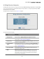
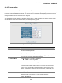
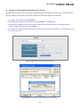
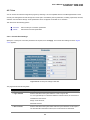
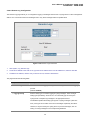
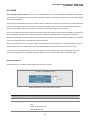
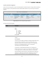
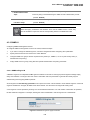
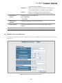
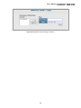
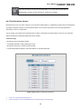
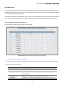
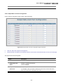
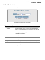
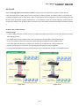
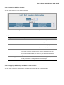
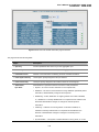
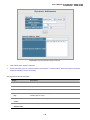
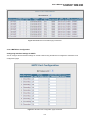
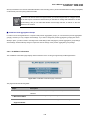
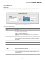
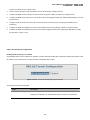
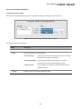
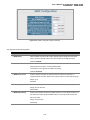
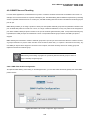
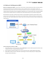
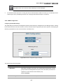
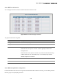
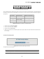
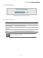
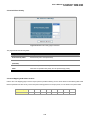
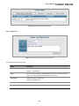
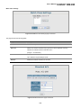
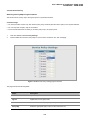
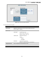
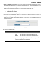
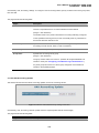
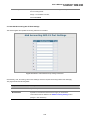
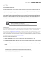
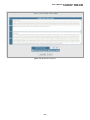
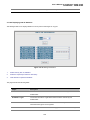
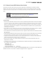
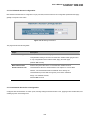
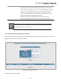
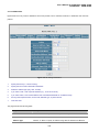
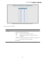
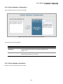
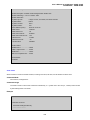
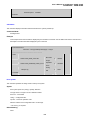
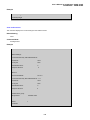
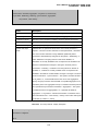
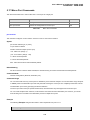
User’s Manual of SGSD-1022 / SGSD-1022P
SGSW-2840 / SGSW-2840P
4.11.13 Access Control Lists
Access Control Lists (ACL) provide packet filtering for IP frames (based on address, protocol, Layer 4 protocol port number or
TCP control code) or any frames (based on MAC address or Ethernet type). To filter incoming packets, first create an access list,
add the required rules, and then bind the list to a specific port.
Configuring Access Control Lists –
An ACL is a sequential list of permit or deny conditions that apply to IP addresses, MAC addresses, or other more specific
criteria. This switch tests ingress or egress packets against the conditions in an ACL one by one. A packet will be accepted as
soon as it matches a permit rule, or dropped as soon as it matches a deny rule. If no rules match for a list of all permit rules, the
packet is dropped; and if no rules match for a list of all deny rules, the packet is accepted.
The following filtering modes are supported:
• Standard IP ACL mode (STD-ACL) filters packets based on the source IP address.
• Extended IP ACL mode (EXT-ACL) filters packets based on source or destination IP address, as well as protocol type and
protocol port number. If the TCP protocol is specified, packets can also be filtered based on the TCP control code.
• MAC ACL mode (MAC-ACL) filters packets based on the source or destination MAC address and the Ethernet frame type
(RFC 1060).
Command Usage
The following restrictions apply to ACLs:
• The maximum number of ACLs is 32.
• Each ACL can have up to 100 rules. However, due to resource restrictions, the average number of rules bound to the ports
should not exceed 20.
The order in which active ACLs are checked is as follows:
• User-defined rules in the Egress IP ACL for egress ports.
• User-defined rules in the Ingress IP ACL for ingress ports.
• Explicit default rule (permit any any) in the ingress IP ACL for ingress ports.
• If no explicit rule is matched, the implicit default is permit all.
4.11.13.1 ACL Configuration
Use the ACL Configuration page to designate the name and type of an ACL.
311
User’s Manual of SGSD-1022 / SGSD-1022P
SGSW-2840 / SGSW-2840P
Figure 4-11-33 Settings screenshot
Select Security, ACL, Configuration. Enter an ACL name in the Name field, select the list type (IP Standard, IP Extended, or
MAC), and click Add to open the configuration page for the new list.
The page includes the following fields:
Object
Description
Name
Name of the ACL.
(Maximum length: 15 characters)
Type
There are three filtering modes:
--Standard
IP ACL mode that filters packets based on the source IP
address.
–- Extended
IP ACL mode that filters packets based on source or destination
IP address, as well as protocol type and protocol port number. If
the “TCP” protocol is specified, then you can also filter packets
based on the TCP control code.
–- MAC
MAC ACL mode that filters packets based on the source or
destination MAC address and the Ethernet frame type (RFC
1060).
312
User’s Manual of SGSD-1022 / SGSD-1022P
SGSW-2840 / SGSW-2840P
4.11.13.2 Configure a Standard ACL
Figure 4-11-34 Settings screenshot
1.
Specify the action (i.e., Permit or Deny).
2.
Select the address type (Any, Host, or IP). If you select “Host,” enter a specific address.
3.
If you select “IP,” enter a subnet address and the mask for an address range.
4.
Then click Add.
The page includes the following fields:
Object
Description
Action
An ACL can contain any combination of permit or deny rules.
Address Type
Specifies the source IP address. Use “Any” to include all possible addresses,
“Host” to specify a specific host address in the Address field, or “IP” to specify a
range of addresses with the Address and SubMask fields. (Options: Any, Host,
IP; Default: Any)
IP Address
Source IP address.
Subnet Mask
A subnet mask containing four integers from 0 to 255, each separated by a
period. The mask uses 1 bits to indicate “match” and 0 bits to indicate “ignore.”
The mask is bitwise ANDed with the specified source IP address, and compared
with the address for each IP packet entering the port(s) to which this ACL has
been assigned.
313
User’s Manual of SGSD-1022 / SGSD-1022P
SGSW-2840 / SGSW-2840P
Figure 4-11-35 Settings screenshot
Figure 4-11-36 Settings screenshot
4.11.13.3 Extended ACL
Specify the action (i.e., Permit or Deny). Specify the source and/or destination addresses. Select the address type (Any, Host, or
IP). If you select “Host,” enter a specific address. If you select “IP,” enter a subnet address and the mask for an address range.
Set any other required criteria, such as service type, protocol type, or TCP control code. Then click Add.
314
User’s Manual of SGSD-1022 / SGSD-1022P
SGSW-2840 / SGSW-2840P
The page includes the following fields:
Object
Description
Action
An ACL can contain any combination of permit or deny rules.
(Default: Permit rules)
Source/Destination
Specifies the source or destination IP address. Use “Any” to include all possible
Address Type
addresses, “Host” to specify a specific host address in the Address field, or “IP”
to specify a range of addresses with the Address and SubMask fields.
Options: Any, Host, IP;
Default: Any
Source/Destination IP
Source or destination IP address.
Address
Source/Destination
Subnet mask for source or destination address.
Subnet Mask
(See the description for Subnet Mask.)
Service Type
Packet priority settings based on the following criteria:
-Precedence – IP precedence level. (Range: 0-7)
-DSCP – DSCP priority level. (Range: 0-63)
Protocol
Specifies the protocol type to match as TCP, UDP or Others, where others
indicates a specific protocol number (0-255).
Options: TCP, UDP, Others;
Default: TCP
Source/Destination Port
Source/destination port number for the specified protocol type.
Start
(Range: 0-65535)
Source/Destination Port
Upper bound of the protocol port range.
End
(Range: 0-65535)
Control Flag
Decimal number (representing a bit string) that specifies flag bits in byte 14 of the
TCP header. (Range: 0-63)
You can specify both Precedence and ToS in the same rule. However, if DSCP is
used, then neither Precedence nor ToS can be specified.
The following control codes may be specified:
-1 (fin) – Finish
-2 (syn) – Synchronize
-4 (rst) – Reset
-8 (psh) – Push
-16 (ack) – Acknowledgement
-32 (urg) – Urgent pointer
To define more than one control code, set the equivalent binary bit to “1” to
indicate the required codes. For example, to set both SYN and ACK valid, set the
control flag to 18.
315
User’s Manual of SGSD-1022 / SGSD-1022P
SGSW-2840 / SGSW-2840P
4.11.13.4 MAC ACL
Egress MAC ACLs only work for destination-mac-known packets, not for multicast, broadcast, or destination-mac-unknown
packets.
Figure 4-11-37 Settings screenshot
1.
Specify the action (i.e., Permit or Deny).
2.
Specify the source and/or destination addresses.
3.
Select the address type (Any, Host, or MAC).
4.
If you select “Host,” enter a specific address (e.g., 11-22-33-44-55-66).
5.
If you select “MAC,” enter a base address and a hexadecimal bitmask for an address range.
6.
Set any other required criteria, such as VID, Ethernet type, or packet format.
7.
Then click Add.
The page includes the following fields:
Object
Description
Action
An ACL can contain any combination of permit or deny rules.
Source/Destination
Use “Any” to include all possible addresses, “Host” to indicate a specific MAC
Address Type
address, or “MAC” to specify an address range with the Address and Bitmask
316
User’s Manual of SGSD-1022 / SGSD-1022P
SGSW-2840 / SGSW-2840P
fields. (Options: Any, Host, MAC; Default: Any)
Source/Destination MAC
Source or destination MAC address.
Address
Source/Destination Bit
Hexadecimal mask for source or destination MAC address.
Mask
VID
VLAN ID. (Range: 1-4094)
Ethernet Type
This option can only be used to filter Ethernet II formatted packets.
(Range: 600-fff hex.)
A detailed listing of Ethernet protocol types can be found in RFC 1060. A few of
the more common types include 0800 (IP), 0806 (ARP), 8137 (IPX).
Packet Format
This attribute includes the following packet types:
-Any – Any Ethernet packet type.
-eth2 – Ethernet II packets.
-802.3 – Ethernet 802.3 packets.
Figure 4-11-38 Settings screenshot
317
User’s Manual of SGSD-1022 / SGSD-1022P
SGSW-2840 / SGSW-2840P
Figure 4-11-39 Settings screenshot
318
User’s Manual of SGSD-1022 / SGSD-1022P
SGSW-2840 / SGSW-2840P
4.11.13.5 ACL Port Binding
After configuring the Access Control Lists (ACL), you can bind the ports that need to filter traffic to the appropriate ACLs. You
can assign one IP access list to any port – IP ingress or MAC ingress.
Figure 4-11-40 Settings screenshot
1.
Click Security, ACL, Port Binding.
2.
Mark the Enable field for the port you want to bind to an ACL for ingress or egress traffic, select the required ACL from the
drop-down list, then click Apply.
The page includes the following fields:
Object
Description
Port
Fixed port or SFP module.
SGSW-2840/SGSW-2840P: Range: 1-28
SGSD-1022/SGSD-1022P: Range: 1-10
IP
Specifies the IP ACL to bind to a port.
MAC
Specifies the MAC ACL to bind to a port.
IN
ACL for ingress packets.
ACL Name
Name of the ACL.
319
User’s Manual of SGSD-1022 / SGSD-1022P
SGSW-2840 / SGSW-2840P
Figure 4-11-41 Settings screenshot
320
User’s Manual of SGSD-1022 / SGSD-1022P
SGSW-2840 / SGSW-2840P
4.11.14 IP Filter
You can create a list of up to 16 IP addresses or IP address groups that are allowed management access to the Managed
Switch through the web interface, SNMP, or Telnet.
Command Usage
• The management interfaces are open to all IP addresses by default. Once you add an entry to a filter list, access to that
interface is restricted to the specified addresses.
• If anyone tries to access a management interface on the switch from an invalid address, the switch will reject the connection,
enter an event message in the system log, and send a trap message to the trap manager.
• IP address can be configured for SNMP, web and Telnet access respectively. Each of these groups can include up to five
different sets of addresses, either individual addresses or address ranges.
• When entering addresses for the same group (i.e., SNMP, web or Telnet), the switch will not accept overlapping address
ranges. When entering addresses for different groups, the switch will accept overlapping address ranges.
• You cannot delete an individual address from a specified range. You must delete the entire range, and reenter the addresses.
• You can delete an address range just by specifying the start address, or by specifying both the start address and end
address.
4.11.14.1 Web IP Filter
You can create IP address groups that are allowed management access to the Managed Switch through the Web interface.
Figure 4-11-42 IP Filter page screenshot
321
User’s Manual of SGSD-1022 / SGSD-1022P
SGSW-2840 / SGSW-2840P
1.
Click Security, IP Filter.
2.
Enter the IP addresses or range of addresses that are allowed management access to an interface, and click Add Web IP
Filtering Entry to update the filter list.
The page includes the following fields:
Object
Description
Web IP Filter
Configures IP address(es) for the web group.
Start IP Address
A single IP address, or the starting address of a range.
End IP Address
The end address of a range.
Add/Remove Filtering
Adds/removes an IP address from the list.
Entry
4.11.14.2 SNMP IP Filter
You can create IP address groups that are allowed management access to the Managed Switch through the SNMP application.
Figure 4-11-43 SNMP IP Filter page screenshot
1.
Click Security, IP Filter.
2.
Enter the IP addresses or range of addresses that are allowed management access to an interface, and click Add SNMP
IP Filtering Entry to update the filter list.
The page includes the following fields:
322
User’s Manual of SGSD-1022 / SGSD-1022P
SGSW-2840 / SGSW-2840P
Object
Description
SNMP IP Filter
Configures IP address(es) for the SNMP group.
Start IP Address
A single IP address, or the starting address of a range.
End IP Address
The end address of a range.
Add/Remove Filtering
Adds/removes an IP address from the list.
Entry
4.11.14.3 Telnet IP Filter
You can create IP address groups that are allowed management access to the Managed Switch through telnet.
Figure 4-11-44 Telnet IP Filter page screenshot
1.
Click Security, IP Filter.
2.
Enter the IP addresses or range of addresses that are allowed management access to an interface, and click Add Telnet
IP Filtering Entry to update the filter list.
The page includes the following fields:
Object
Description
Telnet IP Filter
Configures IP address(es) for the Telnet group.
Start IP Address
A single IP address, or the starting address of a range.
323
User’s Manual of SGSD-1022 / SGSD-1022P
SGSW-2840 / SGSW-2840P
End IP Address
The end address of a range.
Add/Remove Filtering
Adds/removes an IP address from the list.
Entry
324
User’s Manual of SGSD-1022 / SGSD-1022P
SGSW-2840 / SGSW-2840P
4.11.15 DHCP Snooping
The addresses assigned to DHCP clients on unsecure ports can be carefully controlled using the dynamic bindings registered
with DHCP Snooping (or using the static bindings configured with IP Source Guard). DHCP snooping allows a switch to protect
a network from rogue DHCP servers or other devices which send port-related information to a DHCP server. This information
can be useful in tracking an IP address back to a physical port.
Command Usage
• Network traffic may be disrupted when malicious DHCP messages are received from an outside source. DHCP snooping is
used to filter DHCP messages received on a non-secure interface from outside the network or firewall. When DHCP snooping
is enabled globally and enabled on a VLAN interface, DHCP messages received on an untrusted interface from a device not
listed in the DHCP snooping table will be dropped.
• Table entries are only learned for trusted interfaces. An entry is added or removed dynamically to the DHCP snooping table
when a client receives or releases an IP address from a DHCP server. Each entry includes a MAC address, IP address, lease
time, VLAN identifier, and port identifier.
• The rate limit for the number of DHCP messages that can be processed by the switch is 100 packets per second. Any DHCP
packets in excess of this limit are dropped.
• When DHCP snooping is enabled, DHCP messages entering an untrusted interface are filtered based upon dynamic entries
learned via DHCP snooping.
• Filtering rules are implemented as follows:
-
If the global DHCP snooping is disabled, all DHCP packets are forwarded.
-
If DHCP snooping is enabled globally, and also enabled on the VLAN where the DHCP packet is received, all DHCP
packets are forwarded for a trusted port. If the received packet is a DHCP ACK message, a dynamic DHCP snooping
entry is also added to the binding table.
-
If DHCP snooping is enabled globally, and also enabled on the VLAN where the DHCP packet is received, but the port is
not trusted, it is processed as follows:
o
If the DHCP packet is a reply packet from a DHCP server (including OFFER, ACK or NAK messages), the packet
is dropped.
o
If the DHCP packet is from a client, such as a DECLINE or RELEASE message, the switch forwards the packet
only if the corresponding entry is found in the binding table.
o
If the DHCP packet is from a client, such as a DISCOVER, REQUEST, INFORM, DECLINE or RELEASE
message, the packet is forwarded if MAC address verification is disabled. However, if MAC address verification is
enabled, then the packet will only be forwarded if the client’s hardware address stored in the DHCP packet is the
same as the source MAC address in the Ethernet header.
o
-
If the DHCP packet is not a recognizable type, it is dropped.
If a DHCP packet from a client passes the filtering criteria above, it will only be forwarded to trusted ports in the same
VLAN.
325
User’s Manual of SGSD-1022 / SGSD-1022P
SGSW-2840 / SGSW-2840P
-
If a DHCP packet is from server is received on a trusted port, it will be forwarded to both trusted and untrusted ports in
the same VLAN.
• If the DHCP snooping is globally disabled, all dynamic bindings are removed from the binding table.
• Additional considerations when the switch itself is a DHCP client – The port(s) through which the switch submits a client
request to the DHCP server must be configured as trusted. Note that the switch will not add a dynamic entry for itself to the
binding table when it receives an ACK message from a DHCP server. Also, when the switch sends out DHCP client packets
for itself, no filtering takes place. However, when the switch receives any messages from a DHCP server, any packets
received from untrusted ports are dropped.
4.11.15.1 DHCP Snooping Configuration
Use the DHCP Snooping Configuration page to enable DHCP Snooping globally on the Managed Switch, or to configure MAC
Address Verification.
Figure 4-11-45 DHCP Snooping Configuration page screenshot
The page includes the following fields:
Object
Description
• DHCP Snooping Status
Enables DHCP snooping globally. (Default: Disabled)
• DHCP Snooping
Enables or disables MAC address verification. DHCP packets will be dropped if
MAC-Address
the source MAC address in the Ethernet header of the packet is not same as the
Verification
client’s hardware address in the DHCP packet.
4.11.15.2 DHCP Snooping VLAN Configuration
Enables DHCP snooping on the specified VLAN.
Command Usage
326
User’s Manual of SGSD-1022 / SGSD-1022P
SGSW-2840 / SGSW-2840P
• When DHCP snooping is enabled globally on the switch, and enabled on the specified VLAN, DHCP packet filtering will be
performed on any untrusted ports within the VLAN.
• When the DHCP snooping is globally disabled, DHCP snooping can still be configured for specific VLANs, but the changes
will not take effect until DHCP snooping is globally re-enabled.
• When DHCP snooping is globally enabled, and DHCP snooping is then disabled on a VLAN, all dynamic bindings learned for
this VLAN are removed from the binding table.
Figure 4-11-46 DHCP Snooping VLAN Configuration page screenshot
The page includes the following fields:
Object
Description
• VLAN ID
ID of a configured VLAN. (Range: 1-4094)
• DHCP Snooping Status
Enables or disables DHCP snooping for the selected VLAN.
4.11.15.3 Information Option Configuration
DHCP provides a relay mechanism for sending information about the switch and its DHCP clients to DHCP servers. Known as
DHCP Option 82, it allows compatible DHCP servers to use the information when assigning IP addresses, or to set other
services or policies for clients. It is also an effective tool in preventing malicious network attacks from attached clients on DHCP
services, such as IP Spoofing, Client Identifier Spoofing, MAC Address Spoofing, and Address Exhaustion.
Command Usage
• DHCP Snooping must be enabled for Option 82 to function.
• When Option 82 is enabled, the requesting client (or an intermediate relay agent that has used the information fields to
describe itself) can be identified in the DHCP request packets forwarded by the switch and in reply packets sent back from
the DHCP server.
• If Option 82 is enabled on the switch, client information may be included in any relayed request packet.
• DHCP request packets are flooded onto all attached VLANs other than the inbound VLAN under the following situations:
327
User’s Manual of SGSD-1022 / SGSD-1022P
SGSW-2840 / SGSW-2840P
-
DHCP snooping is disabled.
-
The request packet contains a valid relay agent address field.
DHCP reply packets received by the relay agent (that is, this switch) are handled in the following way:
1.
When the relay agent receives a DHCP reply packet with Option 82 information, it first ensures that the packet is
destined for it, and then removes the Option 82 field from the packet.
2.
If the DHCP packet’s broadcast flag is on, the reply packet is broadcast to all attached VLANs, excluding that through
which the reply packet was received. If the DHCP packet’s broadcast flag is off, the switch uses the Option 82
information to identify the interface connected to the requesting client and unicasts the reply packet to the client.
DHCP reply packets are flooded onto all attached VLANs other than the inbound VLAN under the following situations:
-
The reply packet does not contain Option 82 information.
-
The reply packet contains a valid relay agent address field (that is not the address of this switch) or a zero relay address.
• In some cases, the Managed Switch may receive DHCP packets from a client that already includes DHCP Option 82 information.
The switch can be configured to set the action policy for these packets. Either the Managed Switch can discard the Option 82
information, keep the existing information, or replace it with the switch’s relay information.
Figure 4-11-47 DHCP Snooping Information Option Configuration page screenshot
The page includes the following fields:
Object
Description
• DHCP Snooping
Enables or disables DHCP Option 82 information relay.
Information Option
(Default: Disabled)
Status
• DHCP Snooping
Sets the DHCP snooping information option policy for DHCP client packets that
Information Option
include Option 82 information.
Policy
• Drop
Discards the Option 82 information in a packet and then floods it to
the entire VLAN.
• Keep
Retain the Option 82 information in the client request, insert the
relay agent’s address (when DHCP snooping is enabled), and
unicast the packet to the DHCP server.
• Replace
Replace the Option 82 information in the client’s request with
information about the relay agent itself, insert the relay agent’s
328
User’s Manual of SGSD-1022 / SGSD-1022P
SGSW-2840 / SGSW-2840P
address (when DHCP snooping is enabled), and unicast the
packet to the DHCP server.
(This is the default policy.)
4.11.15.4 DHCP Snooping Port Configuration
Configures switch ports as trusted or untrusted.
Command Usage
• A trusted interface is an interface that is configured to receive only messages from within the network. An untrusted interface
is an interface that is configured to receive messages from outside the network or firewall.
• When DHCP snooping enabled both globally and on a VLAN, DHCP packet filtering will be performed on any untrusted ports
within the VLAN.
• When an untrusted port is changed to a trusted port, all the dynamic DHCP snooping bindings associated with this port are
removed.
• Set all ports connected to DHCP servers within the local network or firewall to trusted state. Set all other ports outside the
local network or firewall to untrusted state.
Figure 4-11-48 DHCP Snooping Port Configuration page screenshot
The page includes the following fields:
Object
Description
• Trust Status
Enables or disables port as trusted.
329
User’s Manual of SGSD-1022 / SGSD-1022P
SGSW-2840 / SGSW-2840P
4.11.16 IP Source Guard
IP Source Guard is a security feature that filters IP traffic on network interfaces based on manually configured entries in the IP
Source Guard table, or dynamic entries in the DHCP Snooping table when enabled (see “DHCP Snooping”). IP source guard
can be used to prevent traffic attacks caused when a host tries to use the IP address of a neighbor to access the network. This
section describes commands used to configure IP Source Guard.
4.11.16.1 Port Configuration
IP Source Guard is used to filter traffic on an unsecure port which receives messages from outside the network or firewall, and
therefore may be subject to traffic attacks caused by a host trying to use the IP address of a neighbor.
Command Usage
• Setting source guard mode to SIP (Source IP) or SIP-MAC (Source IP and MAC) enables this function on the selected port.
Use the SIP option to check the VLAN ID, source IP address, and port number against all entries in the binding table. Use the
SIP-MAC option to check these same parameters, plus the source MAC address. If no matching entry is found, the packet is
dropped.
• When enabled, traffic is filtered based upon dynamic entries learned via DHCP snooping (see “Configuring DHCP
Snooping”), or static addresses configured in the source guard binding table.
• If IP source guard is enabled, an inbound packet’s IP address (sip option) or both its IP address and corresponding MAC
address (sip-mac option) will be checked against the binding table. If no matching entry is found, the packet will be dropped.
• Filtering rules are implemented as follows:
-
If the DHCP snooping is disabled, IP source guard will check the VLAN ID, source IP address, port number, and
source MAC address (for the sip-mac option). If a matching entry is found in the binding table and the entry type is
static IP source guard binding, the packet will be forwarded.
-
If the DHCP snooping is enabled, IP source guard will check the VLAN ID, source IP address, port number, and
source MAC address (for the sip-mac option). If a matching entry is found in the binding table and the entry type is
static IP source guard binding, or dynamic DHCP snooping binding, the packet will be forwarded.
-
If IP source guard if enabled on an interface for which IP source bindings have not yet been configured (neither by
static configuration in the IP source guard binding table nor dynamically learned from DHCP snooping), the switch will
drop all IP traffic on that port, except for DHCP packets.
330
User’s Manual of SGSD-1022 / SGSD-1022P
SGSW-2840 / SGSW-2840P
Figure 4-11-49 IP Source Guard Port Configuration page screenshot
The page includes the following fields:
Object
Description
Filter Type
Configures the switch to filter inbound traffic based source IP address, or source
IP address and corresponding MAC address.
• None
Disables IP source guard filtering on the port.
• SIP
Enables traffic filtering based on IP addresses stored in the
binding table.
• SIP-MAC
Enables traffic filtering based on IP addresses and corresponding
MAC addresses stored in the binding table.
(Default: None)
331
User’s Manual of SGSD-1022 / SGSD-1022P
SGSW-2840 / SGSW-2840P
4.11.16.2 Static Configuration
Add a static address to the source-guard binding table. Table entries include a MAC address, IP address, lease time, entry type
(Static, Dynamic), VLAN identifier, and port identifier. All static entries are configured with an infinite lease time, which is
indicated with a value of zero in the table.
Command Usage
• Static addresses entered in the source guard binding table are automatically configured with an infinite lease time. Dynamic
entries learned via DHCP snooping are configured by the DHCP server itself, of which static entries include a manually
configured lease time.
• Static bindings are processed as follows:
-
If there is no entry with the same VLAN ID and MAC address, a new entry is added to the binding table using the type
“static IP source guard binding.”
-
If there is an entry with the same VLAN ID and MAC address, and the type of entry is static IP source guard binding,
then the new entry will replace the old one.
-
If there is an entry with the same VLAN ID and MAC address, and the type of the entry is dynamic DHCP snooping
binding, then the new entry will replace the old one and the entry type will be changed to static IP source guard
binding.
Figure 4-11-50 static IP source guard binding page screenshot
1.
Click IP Source Guard, Static Configuration.
2.
Select the VLAN and port to which the entry will be bound, enter the MAC address and associated IP address, then click
Add.
332
User’s Manual of SGSD-1022 / SGSD-1022P
SGSW-2840 / SGSW-2840P
The page includes the following fields:
Object
Description
Static Binding Table
The total number of static entries in the table.
Counts
Switch port number.
Port
SGSW-2840/SGSW-2840P Range: 1-28
SGSD-1022/SGSD-1022P Range: 1-10
ID of a configured VLAN
VLAN ID
(Range: 1-4094)
MAC Address
A valid unicast MAC address.
IP Address
A valid unicast IP address, including classful types A, B or C.
4.11.16.3 Dynamic Information
Use the Dynamic Information page to display the source-guard binding table for a selected interface.
Figure 4-11-51 Dynamic IP source guard binding Information page screenshot
333
User’s Manual of SGSD-1022 / SGSD-1022P
SGSW-2840 / SGSW-2840P
The page includes the following fields:
Object
Description
Query by
Select an interface to display the source-guard binding.
Options:
-
Port
-
VLAN
-
MAC Address
-
IP Address
Dynamic Binding Table Counts
Displays the number of IP addresses in the source-guard binding table.
Current Dynamic Binding Table
Displays the IP addresses in the source-guard binding table.
334
User’s Manual of SGSD-1022 / SGSD-1022P
SGSW-2840 / SGSW-2840P
4.12 Cluster
Switch Clustering is a method of grouping switches together to enable centralized management through a single unit. Switches
that support clustering can be grouped together regardless of physical location or switch type, as long as they are connected to
the same local network.
Command Usage
• A switch cluster has a “Commander” unit that is used to manage all other “Member” switches in the cluster. The
management station can use both Telnet and the web interface to communicate directly with the Commander through its IP
address, while the Commander manages Member switches using the cluster’s “internal” IP addresses.
• There can be up to 36 Member switches in one cluster, and Cluster switches must be in the same IP subnet.
• Once a switch has been configured to be a cluster Commander, it automatically discovers other cluster-enabled switches in
the network. These “Candidate” switches only become cluster Members when manually selected by the administrator
through the management station.
• Cluster switches are limited to the same Ethernet broadcast domain.
• There can be up to 100 candidates and 36 member switches in one cluster.
• A switch can only be a member of one cluster.
• After the Commander and Members have been configured, any switch in the cluster can be managed from the web agent by
choosing the desired Member ID from the Cluster drop down menu. To connect to a Member switch through the CLI, use the
rcommand.
4.12.1 Cluster Configuration
To create a switch cluster, first be sure that clustering is enabled on the switch (the default is enabled), then set the switch as a
Cluster Commander. Set a Cluster IP Pool that does not conflict with the network IP subnet. Cluster IP addresses are assigned
to switches when they become Members and are used for communication between Member switches and the Commander.
335
User’s Manual of SGSD-1022 / SGSD-1022P
SGSW-2840 / SGSW-2840P
Figure 4-12-1 Cluster Configuration page screenshot
The page includes the following fields:
Object
Description
Cluster Status
Enables or disables clustering on the switch.
(Default: Enabled)
Cluster Commander
Enables or disables the switch as a cluster Commander.
(Default: Disabled)
Role
Indicates the current role of the switch in the cluster; either Commander,
Member, or Candidate.
(Default: Candidate)
Cluster IP Pool
An “internal” IP address pool that is used to assign IP addresses to Member
switches in the cluster. Internal cluster IP addresses are in the form
10.x.x.member-ID.
Only the base IP address of the pool needs to be set since Member IDs can only
be between 1 and 36. Note that you cannot change the cluster IP pool when
the switch is currently in Commander mode. Commander mode must first be
disabled.
(Default: 10.254.254.1)
Number of Members
The current number of Member switches in the cluster.
Number of Candidates
The current number of Candidate switches discovered in the network that are
available to become Members.
336
User’s Manual of SGSD-1022 / SGSD-1022P
SGSW-2840 / SGSW-2840P
4.12.2 Cluster Member Configuration
Adds Candidate switches to the cluster as Members.
Figure 4-12-2 Cluster Member Configuration page screenshot
The page includes the following fields:
Object
Description
Member ID
Specify a Member ID number for the selected Candidate switch.
(Range: 1-36)
MAC Address
Select a discoverd switch MAC address from the Candidate Table, or enter a
specific MAC address of a known switch.
4.12.3 Cluster Member Information
Displays current cluster Member switch information.
337
User’s Manual of SGSD-1022 / SGSD-1022P
SGSW-2840 / SGSW-2840P
Figure 4-12-3 Cluster Member Information page screenshot
The page includes the following fields:
Object
Description
Member ID
The ID number of the Member switch.
(Range: 1-36)
Role
Indicates the current status of the switch in the cluster.
IP Address
The internal cluster IP address assigned to the Member switch.
MAC Address
The MAC address of the Member switch.
Description
The system description string of the Member switch.
4.12.4 Cluster Candidate Information
Displays information about discovered switches in the network that are already cluster Members or are available to become
cluster Members.
Figure 4-12-4 Cluster Candidate Information page screenshot
338
User’s Manual of SGSD-1022 / SGSD-1022P
SGSW-2840 / SGSW-2840P
The page includes the following fields:
Object
Description
Role
Indicates the current status of Candidate switches in the network.
MAC Address
The MAC address of the Candidate switch.
Description
The system description string of the Candidate switch.
339
User’s Manual of SGSD-1022 / SGSD-1022P
SGSW-2840 / SGSW-2840P
4.13 Power Over Ethernet (SGSD-1022P / SGSW-2840P / SGSW-2840P4)
Providing up to 8/24 PoE, in-line power interface, the SGSD-1022P / SGSW-2840P PoE Switch can easily build a power
central-controlled IP phone system, IP Camera system, AP group for the enterprise. For instance, 8 camera / AP can be easily
installed around the corner in the company for surveillance demands or build a wireless roaming environment in the office.
Without the power-socket limitation, the PoE Switch makes the installation of cameras or WLAN AP more easily and efficiently.
4.13.1 Power over Ethernet Powered Device
Voice over IP phones
Enterprise can install POE VoIP Phone, ATA and other Ethernet/non-Ethernet
end-devices to the central where UPS is installed for un-interrupt power system
3~5 watts
and power control system.
Wireless LAN Access Points
Museum, Sightseeing,
Airport, Hotel, Campus, Factory, Warehouse can
install the Access Point any where with no hesitation
6~12 watts
IP Surveillance
Enterprise, Museum, Campus, Hospital, Bank, can install IP Camera without
limits of install location – no need electrician to install AC sockets.
10~12 watts
PoE Splitter
PoE Splitter split the PoE 48V DC over the Ethernet cable into 5/9/12V DC
power output. It frees the device deployment from restrictions due to power
outlet locations, which eliminate the costs for additional AC wiring and reduces
3~12 watts
the installation time.
340
User’s Manual of SGSD-1022 / SGSD-1022P
SGSW-2840 / SGSW-2840P
4.13.2 Power Management:
In a power over Ethernet system, operating power is applied from a power source (PSU-power supply unit) over the LAN
infrastructure to powered devices (PDs), which are connected to ports. Under some conditions, the total output power required
by PDs can exceed the maximum available power provided by the PSU. The system may a prior be planed with a PSU capable
of supplying less power than the total potential power consumption of all the PoE ports in the system. In order to maintain the
majority of ports active, power management is implemented.
The PSU input power consumption is monitored by measuring voltage and current .The input power consumption is equal to the
system’s aggregated power consumption .The power management concept allows all ports to be active and activates additional
ports, as long as the aggregated power of the system is lower than the power level at which additional PDs cannot be
connected .When this value is exceeded, ports will be deactivated, according to user-defined priorities. The power budget is
managed according to the following user-definable parameters: maximum available power, ports priority, maximum allowable
power per port.
This section provides PoE (Power over Ethernet) Configuration and PoE output status of PoE Switch, screen in Figure 4-13-1
appears.
Figure 4-13-1
341
User’s Manual of SGSD-1022 / SGSD-1022P
SGSW-2840 / SGSW-2840P
The page includes the following fields:
Object
Description
Power limit mode
Allow to configure power limit mode of Web Smart Device. It can choose :
„
Port Priority Deliver PoE power by port priority setting
„
Total Limit. Set limit value of the total POE port provided power to the PDs.
Power Consumption
Show the total watts usage of PoE Switch.
PoE Function
Can enable or disable the PoE function.
Priority
Set port priority for the POE power management
It can choose the “port priority”, value is “1~4”.
High priority is “1”.
Device class
Class 0 is the default for PDs. However, to improve power management at the
PSE, the PD may opt to provide a signature for Class 1 to 3.
The PD is classified based on power. The classification of the PD is the maximum
power that the PD will draw across all input voltages and operational modes. A
PD shall return Class 0 to 3 in accordance with the maximum power draw as
specified by Table 4.1.
Current(mA)
It shows the PoE device current Amp.
Consumption [W]
It shows the PoE device current watt.
Power Limit
It can limit the port PoE supply watts.
Per port maximum value must less 15.4, total ports values must less than the
Power Reservation value.
Once power overload detected, the port will auto shut down and keep on
detection mode until PD’s power consumption lower than the power limit value.
For SGSW-2840P, the total PoE power reservation from Port-1~24 is up to 220W
For SGSW-2840P4, the total PoE power reservation from Port-1~24 is up to 380W
For SGSD-1022, the total PoE power reservation from Port-1~8 is up to 110W
„
PD Classifications
A PD may be classified by the PSE based on the classification information provided by the PD. The intent of PD classification is
to provide information about the maximum power required by the PD during operation. Class 0 is the default for PDs. However,
to improve power management at the PSE, the PD may opt to provide a signature for Class 1 to 3.
The PD is classified based on power. The classification of the PD is the maximum power that the PD will draw across all input
voltages and operational modes.
A PD shall return Class 0 to 3 in accordance with the maximum power draw as specified by Table 4-13-1.
342
User’s Manual of SGSD-1022 / SGSD-1022P
SGSW-2840 / SGSW-2840P
Class
Usage
Range of maximum power used by the PD
0
Default
0.44 to 12.95 Watts
1
Optional
0.44 to 3.84 Watts
2
Optional
3.84 to 6.49 Watts
3
Optional
6.49 to 12.95 Watts
4
Not Allowed
Reserved for Future Use
Table 4.13-1 Device class
Class 4 is defined but is reserved for future use. A Class 4 signature cannot be provided by a
compliant PD.
343
User’s Manual of SGSD-1022 / SGSD-1022P
SGSW-2840 / SGSW-2840P
5. COMMAND LINE INTERFACE
This chapter describes how to use the Command Line Interface (CLI).
5.1 Using the Command Line Interface
5.1.1 Accessing the CLI
When accessing the management interface for the switch over a direct connection to the server’s console port, or via a Telnet
connection, the switch can be managed by entering command keywords and parameters at the prompt. Using the switch's
command-line interface (CLI) is very similar to entering commands on a UNIX system.
5.1.2 Console Connection
To access the switch through the console port, perform these steps:
1.
At the console prompt, enter the user name and password. (The default user names are “admin” and “guest” with
corresponding passwords of “admin” and “guest.”) When the administrator user name and password is entered, the CLI
displays the “Console#” prompt and enters privileged access mode (i.e., Privileged Exec). But when the guest user name
and password is entered, the CLI displays the “Console>” prompt and enters normal access mode (i.e., Normal Exec).
2.
Enter the necessary commands to complete your desired tasks.
3.
When finished, exit the session with the “quit” or “exit” command.
After connecting to the system through the console port, the login screen displays:
User Access Verification
Username: admin
Password:
CLI session with the SGSD-1022 is opened.
To end the CLI session, enter [Exit].
Console#
5.1.3 Telnet Connection
Telnet operates over the IP transport protocol. In this environment, your management station and any network device you want
to manage over the network must have a valid IP address. Valid IP addresses consist of four numbers, 0 to 255, separated by
periods. Each address consists of a network portion and host portion. For example, the IP address assigned to this switch,
10.1.0.1, with subnet mask 255.255.255.0, consists of a network portion (10.1.0) and a host portion (1).
344
User’s Manual of SGSD-1022 / SGSD-1022P
SGSW-2840 / SGSW-2840P
The IP address for this switch is obtained via DHCP by default.
To access the switch through a Telnet session, you must first set the IP address for the switch, and set the default gateway if you
are managing the switch from a different IP subnet. For example,
Console(config)# interface vlan 1
Console(config-if)# ip address 10.1.0.254 255.255.255.0
Console(config-if)# exit
Console(config)# ip default-gateway 10.1.0.254
If your corporate network is connected to another network outside your office or to the Internet, you need to apply for a
registered IP address. However, if you are attached to an isolated network, then you can use any IP address that matches the
network segment to which you are attached.
After you configure the switch with an IP address, you can open a Telnet session by performing these steps:
1.
From the remote host, enter the Telnet command and the IP address of the device you want to access.
2.
At the prompt, enter the user name and system password. The CLI will display the “Vty-n#” prompt for the administrator to
show that you are using privileged access mode (i.e., Privileged Exec), or “Vty-n>” for the guest to show that you are
using normal access mode (i.e., Normal Exec), where n indicates the number of the current Telnet session.
3.
Enter the necessary commands to complete your desired tasks.
4.
When finished, exit the session with the “quit” or “exit” command.
After entering the Telnet command, the login screen displays:
Username: admin
Password:
CLI session with the SGSD-1022 is opened.
To end the CLI session, enter [Exit].
Vty-0#
345
User’s Manual of SGSD-1022 / SGSD-1022P
SGSW-2840 / SGSW-2840P
You can open up to four sessions to the device via Telnet.
5.2 Entering Commands
This section describes how to enter CLI commands.
5.2.1 Keywords and Arguments
A CLI command is a series of keywords and arguments. Keywords identify a command, and arguments specify configuration
parameters. For example, in the command “show interfaces status ethernet 1/5,” show interfaces and status are keywords,
ethernet is an argument that specifies the interface type, and 1/5 specifies the unit/port.
You can enter commands as follows:
To enter a simple command, enter the command keyword.
To enter multiple commands, enter each command in the required order. For example, to enable Privileged Exec Command
Mode, and display the startup configuration, enter:
Console>enable
Console# show startup-config
• To enter commands that require parameters, enter the required parameters after the command keyword. For example, to set a
password for the administrator, enter:
Console(config)# username admin password 0 smith
5.2.2 Minimum Abbreviation
The CLI will accept a minimum number of characters that uniquely identify a command. For example, the command “configure”
can be entered as con. If an entry is ambiguous, the system will prompt for further input.
5.2.3 Command Completion
If you terminate input with a Tab key, the CLI will print the remaining characters of a partial keyword up to the point of ambiguity.
In the “logging history” example, typing log followed by a tab will result in printing the command up to “logging.”
5.2.4 Getting Help on Commands
You can display a brief description of the help system by entering the help command. You can also display command syntax by
346
User’s Manual of SGSD-1022 / SGSD-1022P
SGSW-2840 / SGSW-2840P
using the “?” character to list keywords or parameters.
5.2.5 Showing Commands
If you enter a “?” at the command prompt, the system will display the first level of keywords for the current command class
(Normal Exec or Privileged Exec) or configuration class (Global, ACL, Interface, Line or VLAN Database). You can also display
a list of valid keywords for a specific command. For example, the command “show ?” displays a list of possible show
commands:
Console# show ?
access-group
Access groups
access-list
Access lists
accounting
Uses an accounting list with this name
banner
Banner info
bridge-ext
Bridge extension information
calendar
Date and time information
class-map
Displays class maps
cluster
Display cluster
dot1q-tunnel
dot1q-tunnel
dot1x
802.1x content
garp
GARP properties
gvrp
GVRP interface information
history
History information
interfaces
Interface information
ip
IP information
lacp
LACP statistics
line
TTY line information
lldp
LLDP
log
Login records
logging
Logging setting
mac
MAC access list
mac-address-table
Shows the MAC address table
management
Show management information
map
Maps priority
mvr
Show mvr interface information
network-access
Shows the entries of the secure port.
policy-map
Displays policy maps
port
Port characteristics
private-vlan
Private VLAN
347
User’s Manual of SGSD-1022 / SGSD-1022P
SGSW-2840 / SGSW-2840P
privilege
Shows current privilege level
process
Device process
protocol-vlan
Protocol-VLAN information
public-key
Public key information
queue
Priority queue information
radius-server
RADIUS server information
running-config
Information on the running configuration
snmp
Simple Network Management Protocol statistics
sntp
Simple Network Time Protocol configuration
spanning-tree
Spanning-tree configuration
ssh
Secure shell server connections
startup-config
Startup system configuration
system
System information
tacacs-server
TACACS server settings
users
Information about terminal lines
version
System hardware and software versions
vlan
Virtual LAN settings
voice
Shows the voice VLAN information
web-auth
Shows web authentication configuration
The command “show interfaces ?” will display the following information:
Console# show interfaces ?
counters
Interface counters information
protocol-group
Protocol group
status
Interface status information
switchport
Interface switchport information
Console#show interfaces
348
User’s Manual of SGSD-1022 / SGSD-1022P
SGSW-2840 / SGSW-2840P
5.2.6 Partial Keyword Lookup
If you terminate a partial keyword with a question mark, alternatives that match the initial letters are provided. (Remember not to
leave a space between the command and question mark.) For example “s?” shows all the keywords starting with “s.”
Console# show s?
snmp
sntp
spanning-tree
ssh startup-config
System
Console# show s
5.2.7 Negating the Effect of Commands
For many configuration commands you can enter the prefix keyword “no” to cancel the effect of a command or reset the
configuration to the default value. For example, the logging command will log system messages to a host server. To disable
logging, specify the no logging command. This guide describes the negation effect for all applicable commands.
5.2.8 Using Command History
The CLI maintains a history of commands that have been entered. You can scroll back through the history of commands by
pressing the up arrow key. Any command displayed in the history list can be executed again, or first modified and then
executed.
Using the show history command displays a longer list of recently executed commands.
5.2.9 Understanding Command Modes
The command set is divided into Exec and Configuration classes. Exec commands generally display information on system
status or clear statistical counters. Configuration commands, on the other hand, modify interface parameters or enable certain
switching functions. These classes are further divided into different modes. Available commands depend on the selected mode.
You can always enter a question mark “?” at the prompt to display a list of the commands available for the current mode. The
command classes and associated modes are displayed in the following table:
Class
Mode
Exec
Normal
Privileged
Configuration
Global*
Access Control List
Class Map
Interface
Line
Multiple Spanning Tree
Policy Map
Server Group
349
User’s Manual of SGSD-1022 / SGSD-1022P
SGSW-2840 / SGSW-2840P
VLAN Database
Table 5-1 Command Modes
1.
You must be in Privileged Exec mode to access the Global configuration mode.
2.
You must be in Global Configuration mode to access any of the other configuration modes.
5.2.10 Exec Commands
When you open a new console session on the switch with the user name and password “guest,” the system enters the Normal
Exec command mode (or guest mode), displaying the “Console>” command prompt. Only a limited number of the commands
are available in this mode. You can access all commands only from the Privileged Exec command mode (or administrator mode).
To access Privilege Exec mode, open a new console session with the user name and password “admin.” The system will now
display the “Console#” command prompt. You can also enter Privileged Exec mode from within Normal Exec mode, by entering
the enable command, followed by the privileged level password “super”.
To enter Privileged Exec mode, enter the following user names and passwords:
Username: admin
Password: [admin login password]
CLI session with the SGSD-1022 is opened.
To end the CLI session, enter [Exit].
Console#
Username: guest
Password: [guest login password]
CLI session with the SGSD-1022 is opened.
To end the CLI session, enter [Exit].
Console>enable
Password: [privileged level password]
Console#
350
User’s Manual of SGSD-1022 / SGSD-1022P
SGSW-2840 / SGSW-2840P
5.2.11 Configuration Commands
Configuration commands are privileged level commands used to modify switch settings. These commands modify the running
configuration only and are not saved when the switch is rebooted. To store the running configuration in non-volatile storage, use
the copy running-config startup-config command.
The configuration commands are organized into different modes:
• Global Configuration -
These commands modify the system level configuration, and include
commands such as hostname and snmp-server community.
• Access Control List Configuration -
These commands are used for packet filtering.
• Class Map Configuration -
Creates a DiffServ class map for a specified traffic type.
• Interface Configuration -
These commands modify the port configuration such as speed-duplex and
negotiation.
• Line Configuration -
These commands modify the console port and Telnet configuration, and
include command such as parity and data bits.
• Multiple Spanning Tree Configuration - These commands configure settings for the selected multiple spanning tree
instance.
• Policy Map Configuration -
Creates a DiffServ policy map for multiple interfaces.
• VLAN Configuration -
Includes the command to create VLAN groups.
To enter the Global Configuration mode, enter the command configure in Privileged Exec mode. The system prompt will
change to “Console(config)#” which gives you access privilege to all Global Configuration commands.
Console# configure
Console(config)#
To enter the other modes, at the configuration prompt type one of the following commands. Use the exit or end command to
return to the Privileged Exec mode.
Mode
Command
Prompt
Line
line {console | vty}
Console(config-line)#
Access Control
access-list ip standard
Console(config-std-acl)
List
access-list ip extended
Console(config-ext-acl)
access-list mac
Console(config-mac-acl)
Class Map
class map
Console(config-cmap)
Interface
interface {ethernet port |
Console(config-if)#
port-channel id| vlan id}
MSTP
spanning-tree
Console(config-mstp)#
mst-configuration
351
User’s Manual of SGSD-1022 / SGSD-1022P
SGSW-2840 / SGSW-2840P
Policy Map
policy map
Console(config-pmap)
Server Group
aaa group server radius
Console(config-sg-radius)
aaa group server tacacs+
Console(config-sg-tacacs+)
vlan database
Console(config-vlan)
VLAN
Table 5-2 Configuration Modes
For example, you can use the following commands to enter interface configuration mode, and then return to Privileged Exec
mode
Console(config)# interface ethernet 1/5
Console(config-if)# exit
Console(config)#
5.2.12 Command Line Processing
Commands are not case sensitive. You can abbreviate commands and parameters as long as they contain enough letters to
differentiate them from any other currently available commands or parameters. You can use the Tab key to complete partial
commands, or enter a partial command followed by the “?” character to display a list of possible matches. You can also use the
following editing keystrokes for command-line processing:
Keystroke
Function
Ctrl-A
Shifts cursor to start of command line.
Ctrl-B
Shifts cursor to the left one character.
Ctrl-C
Terminates the current task and displays the command prompt.
Ctrl-E
Shifts cursor to end of command line.
Ctrl-F
Shifts cursor to the right one character.
Ctrl-K
Deletes all characters from the cursor to the end of the line.
Ctrl-L
Repeats current command line on a new line.
Ctrl-N
Enters the next command line in the history buffer.
Ctrl-P
Enters the last command.
Ctrl-R
Repeats current command line on a new line.
Ctrl-U
Deletes from the cursor to the beginning of the line.
Ctrl-W
Deletes the last word typed.
Esc-B
Moves the cursor back one word.
Esc-D
Deletes from the cursor to the end of the word.
Esc-F
Moves the cursor forward one word.
Delete key or
Erases a mistake when entering a command.
backspace key
Table 5-3 Command Line Processing
352
User’s Manual of SGSD-1022 / SGSD-1022P
SGSW-2840 / SGSW-2840P
5.3 Command Groups
The system commands can be broken down into the functional groups shown below.
Command Group
Description
General
Basic commands for entering privileged access mode, restarting thesystem, or quitting
the CLI
System Management
Display and setting of system information, basic modes of operation, maximum frame
size, file management, console port and telnet settings, system logs, SMTP alerts,
system clock, and switch clustering
Simple Network
Activates authentication failure traps; configures community accessstrings, and trap
Management
receivers
Protocol
Authentication
Configures user names and passwords, logon access using local orremote
authentication (including AAA), management access through the web server, Telnet
server and Secure Shell; as well as port security, IEEE 802.1X port access control, and
restricted access based on specified IP addresses
Client Security
Segregates traffic for clients attached to common data ports; and prevents unauthorized
access by configuring valid static or dynamicaddresses, and filtering DHCP requests
and replies
Access Control List
Provides filtering for IP frames (based on address, protocol, or TCP/UDP port number or
TCP control code) or non-IP frames (based onMAC address or Ethernet type)
Interface
Configures the connection parameters for all Ethernet ports,aggregated links, and
VLANs
Link Aggregation
Statically groups multiple ports into a single logical trunk; configures Link Aggregation
Control Protocol for port trunks
Mirror Port
Mirrors data to another port for analysis without affecting the data passing through or the
performance of the monitored port
Rate Limiting
Controls the maximum rate for traffic transmitted or received on a port
Address Table
Configures the address table for filtering specified addresses, displays current entries,
clears the table, or sets the aging time
Spanning Tree
Configures Spanning Tree settings for the switch
VLANs
Configures VLAN settings, and defines port membership for VLAN groups; also enables
or configures private VLANs, protocol VLANs,and voice VLANs
Link Layer Discovery
Configures LLDP settings to enable information discovery aboutneighbor devices
Protocol
Class of Service
Sets port priority for untagged frames, selects strict priority or weightedround robin,
relative weight for each priority queue, also sets priority for TCP/UDP traffic types, and
DSCP
353
User’s Manual of SGSD-1022 / SGSD-1022P
SGSW-2840 / SGSW-2840P
Quality of Service
Configures Differentiated Services
Multicast Filtering
Configures IGMP multicast filtering, query parameters, specifies ports attached to a
multicast router, and enables multicast VLAN registration
IP Interface
Configures IP address for the switch
Table 5-4 Command Groups
The access mode shown in the following tables is indicated by these abbreviations:
ACL (Access Control List Configuration)
NE (Normal Exec)
CM (Class Map Configuration)
PE (Privileged Exec)
GC (Global Configuration)
PM (Policy Map Configuration)
IC (Interface Configuration)
SG (Server Group)
LC (Line Configuration)
VC (VLAN Database Configuration)
MST (Multiple Spanning Tree)
5.4 General Commands
These commands are used to control the command access mode, configuration mode, and other basic functions.
Command
Function
Mode
enable
Activates privileged mode
NE
disable
Returns to normal mode from privileged mode
PE
configure
Activates global configuration mode
PE
show history
Shows the command history buffer
NE, PE
reload
Restarts the system
PE
prompt
Customizes the prompt used in PE and NE mode
GC
end
Returns to Privileged Exec mode
any config. mode
exit
Returns to the previous configuration mode, or exits the CLI
any
quit
Exits a CLI session
NE, PE
help
Shows how to use help
any
?
Shows options for command completion (context sensitive)
any
Table 4-5 General Commands
enable
This command activates Privileged Exec mode. In privileged mode, additional commands are available, and certain commands
display additional information. See “Understanding Command Modes”.
Syntax
enable [level]
level - Privilege level to log into the device.
354
User’s Manual of SGSD-1022 / SGSD-1022P
SGSW-2840 / SGSW-2840P
The device has two predefined privilege levels:
0: Normal Exec,
15: Privileged Exec.
Enter level 15 to access Privileged Exec mode.
Default Setting
Level 15
Command Mode
Normal Exec
Command Usage
“admin” is the default password required to change the command mode from Normal Exec to Privileged Exec.
(To set this password, see the enable password command.)
The “#” character is appended to the end of the prompt to indicate that the system is in privileged access mode.
Example
Console>enable
Password: [privileged level password]
Console#
Related Commands
disable
enable password
disable
This command returns to Normal Exec mode from privileged mode. In normal access mode, you can only display basic
information on the switch's configuration or Ethernet statistics. To gain access to all commands, you must use the privileged
mode. See “Understanding Command Modes”.
Default Setting
None
Command Mode
Privileged Exec
Command Usage
The “>” character is appended to the end of the prompt to indicate that the system is in normal access mode.
Example
355
User’s Manual of SGSD-1022 / SGSD-1022P
SGSW-2840 / SGSW-2840P
Console#disable
Console>
Related Commands
enable
configure
This command activates Global Configuration mode. You must enter this mode to modify any settings on the switch. You must
also enter Global Configuration mode prior to enabling some of the other configuration modes, including Interface Configuration,
Line Configuration, VLAN Database Configuration, and Multiple Spanning Tree Configuration. See “Understanding Command
Modes”.
Default Setting
None
Command Mode
Privileged Exec
Example
Console#configure
Console(config)
Related Commands
end
show history
This command shows the contents of the command history buffer.
Default Setting
None
Command Mode
Normal Exec, Privileged Exec
Command Usage
The history buffer size is fixed at 10 Execution commands and 10 Configuration commands.
Example
In this example, the show history command lists the contents of the command history buffer:
Console# show history
Execution command history:
2 config
356
User’s Manual of SGSD-1022 / SGSD-1022P
SGSW-2840 / SGSW-2840P
1 show history
Configuration command history:
4 interface vlan 1
3 exit
2 interface vlan 1
1 end
Console#
The ! command repeats commands from the Execution command history buffer when you are in Normal Exec or Privileged
Exec Mode, and commands from the Configuration command history buffer when you are in any of the configuration modes. In
this example, the !2 command repeats the second command in the Execution history buffer (config).
Console#!2
Console#config
Console(config)#
reload
This command restarts the system.
When the system is restarted, it will always run the Power-On Self-Test. It will also retain all
configuration information stored in non-volatile memory by the copy running-config
startup-config command.
Default Setting
None
Command Mode
Privileged Exec
Command Usage
This command resets the entire system.
Example
This example shows how to reset the switch:
Console# reload
357
User’s Manual of SGSD-1022 / SGSD-1022P
SGSW-2840 / SGSW-2840P
System will be restarted, continue <y/n>? y
prompt
This command customizes the CLI prompt. Use the no form to restore the default prompt.
Syntax
prompt string no prompt string - Any alphanumeric string to use for the CLI prompt. (Maximum length: 255 characters)
Default Setting
Console Command Mode Global Configuration
Example
Console(config)#prompt RD2
RD2(config)#
end
This command returns to Privileged Exec mode.
Default Setting
None
Command Mode
Global Configuration, Interface Configuration, Line Configuration, and VLAN Database Configuration.
Example
This example shows how to return to the Privileged Exec mode from the Interface Configuration mode:
Console(config-if)# end
Console#
exit
This command returns to the previous configuration mode or exit the configuration program.
Default Setting
None
Command Mode
Any
Example
This example shows how to return to the Privileged Exec mode from the Global Configuration mode, and then quit the CLI
358
User’s Manual of SGSD-1022 / SGSD-1022P
SGSW-2840 / SGSW-2840P
session:
Console(config)# exit
Console#exit
Press ENTER to start session
User Access Verification
Username:
quit
This command exits the configuration program.
Default Setting
None
Command Mode
Normal Exec, Privileged Exec
Command Usage
The quit and exit commands can both exit the configuration program.
Example
This example shows how to quit a CLI session:
Console# quit
Press ENTER to start session
User Access Verification
Username:
359
User’s Manual of SGSD-1022 / SGSD-1022P
SGSW-2840 / SGSW-2840P
5.5 System Management Commands
These commands are used to control system logs, passwords, user names, browser configuration options, and display or
configure a variety of other system information.
Command Group
Function
Device Designation
Configures information that uniquely identifies this switch
Banner Information
Configures administrative contact, device identification and location
System Status
Displays system configuration, active managers, and version information
Frame Size
Enables support for jumbo frames
File Management
Manages code image or switch configuration files
Line
Sets communication parameters for the serial port, including baud rate and console time-out
Event Logging
Controls logging of error messages
SMTP Alerts
Configures SMTP email alerts
Time (System Clock)
Sets the system clock automatically via SNTP server or manually
Switch Clustering
Configures management of multiple devices via a single IP address
Table 5-6 System Management Commands
5.5.1 Device Designation Commands
Command
Function
Mode
hostname
Specifies the host name for the switch
GC
snmp-server contact
Sets the system contact string
GC
snmp-server location
Sets the system location string
GC
Table 5-7 Device Designation Commands
hostname
This command specifies or modifies the host name for this device. Use the no form to restore the default host name.
Syntax
hostname name no hostname name - The name of this host. (Maximum length: 255 characters)
Default Setting
None
Command Mode
Global Configuration
Example
Console(config)#hostname RD#1
360
User’s Manual of SGSD-1022 / SGSD-1022P
SGSW-2840 / SGSW-2840P
Console(config)#
5.5.2 Banner Information Commands
These commands are used to configure and manage administrative information about the switch, its exact data center location,
details of the electrical and network circuits that supply the switch, as well as contact information for the network administrator
and system manager. This information is only available via the CLI and is automatically displayed before login as soon as a
console or telnet connection has been established.
Command
Function
Mode
banner configure
Configures banner information displayed before login
GC
banner configure company
Configures Company information displayed by the banner
GC
banner configuredc-powerinfo
Configures DC Power information displayed by the banner
GC
banner configuredepartment
Configures Department information displayed by the banner
GC
banner configureequipment-info
Configures Equipment information displayed by the banner
GC
banner configureequipment-location
Configures Equipment Location information displayed by
GC
thebanner
banner configureip-lan
Configures IP and LAN information displayed by the banner
GC
banner configurelp-number
Configures LP Number information displayed by the banner
GC
banner configure manager-info
Configures Manager contact information displayed by
GC
thebanner
banner configure mux
Configures MUX information displayed by the banner
GC
banner configure note
Configures miscellaneous information displayed by the banner
GC
under the Notes heading
show banner
Displays all banner information
NE, PE
Table 5-8 Banner Commands
banner configure
This command is used to interactively specify administrative information for this device.
Syntax
banner configure
Default Setting
None
Command Mode
Global Configuration
Command Usage
The administrator can batch-input all details for the switch with one command. When the administrator finishes typing the
361
User’s Manual of SGSD-1022 / SGSD-1022P
SGSW-2840 / SGSW-2840P
company name and presses the enter key, the script prompts for the next piece of information, and so on, until all
information has been entered. Pressing enter without inputting information at any prompt during the script’s operation will
leave the field empty. Spaces can be used during script mode because pressing the enter key signifies the end of data input.
The delete and left-arrow keys terminate the script. Use of the backspace key during script mode is not supported. If, for
example, a mistake is made in the company name, it can be corrected with the banner configure company command.
Example
Console(config)#banner configure
Company: ABC Co.
Responsible department: R&D Dept
Name and telephone to Contact the management people
Manager1 name: Sr. Network Admin
phone number: 123-555-1212
Manager2 name: Jr. Network Admin
phone number: 123-555-1213
Manager3 name: Night-shift Net Admin / Janitor
phone number: 123-555-1214
The physical location of the equipment.
City and street address: 12 Straight St. Motown, Zimbabwe
Information about this equipment:
Manufacturer: ABC Co.
ID: 123_unique_id_number
Floor: 2
Row: 7
Rack: 29
Shelf in this rack: 8
Information about DC power supply.
Floor: 2
Row: 7
Rack: 25
Electrical circuit: : ec-177743209-xb
Number of LP:12
Position of the equipment in the MUX:1/23
IP LAN:192.168.1.1
Note: This is a random note about this managed switch and can contain
miscellaneous information.
Console(config)#
362
User’s Manual of SGSD-1022 / SGSD-1022P
SGSW-2840 / SGSW-2840P
banner configure company
This command is used to configure company information displayed in the banner. Use the no form to restore the default setting.
Syntax
banner configure company name
no banner configure company
name - The name of the company. (Maximum length: 32 characters)
Default Setting
None
Command Mode
Global Configuration
Command Usage
Input strings cannot contain spaces. The banner configure company command interprets spaces as data input
boundaries. The use of underscores ( _ ) or other unobtrusive non-letter characters is suggested for situations where
whitespace is necessary for clarity.
Example
Console(config)#banner configure company ABC Co.
Console(config)#
banner configure dc-power-info
This command is use to configure DC power information displayed in the banner. Use the no form to restore the default setting.
Syntax
banner configure dc-power-info floor floor-id row row-id rack rack-id electrical-circuit ec-id no banner configure
dc-power-info [floor | row | rack | electrical-circuit]
floor-id - The floor number.
row-id - The row number.
rack-id - The rack number.
ec-id - The electrical circuit ID.
Default Setting
None
Command Mode
Global Configuration
Command Usage
Maximum string length for each command attribute is 32 characters.
363
User’s Manual of SGSD-1022 / SGSD-1022P
SGSW-2840 / SGSW-2840P
Input strings cannot contain spaces. The banner configure dc-power-info command interprets spaces as data input
boundaries.
The use of underscores ( _ ) or other unobtrusive non-letter characters is suggested for situations where whitespace is
necessary for clarity.
Example
Console(config)#banner configure floor 3 row 15 rack 24
electrical-circuit 48v-id_3.15.24.2
Console(config)#
banner configure department
This command is used to configure the department information displayed in the banner. Use the no form to restore the default
setting.
Syntax
banner configure department dept-name no banner configure company dept-name -The name of the department.
(Maximum length: 32 characters)
Default Setting
None
Command Mode
Global Configuration
Command Usage
Input strings cannot contain spaces. The banner configure department command interprets spaces as data input
boundaries. The use of underscores ( _ ) or other unobtrusive non-letter characters is suggested for situations where
whitespace is necessary for clarity.
Example
Console(config)#banner configure department R&D
Console(config)#
banner configure equipment-info
This command is used to configure the equipment information displayed in the banner. Use the no form to restore the default
setting.
Syntax
364
User’s Manual of SGSD-1022 / SGSD-1022P
SGSW-2840 / SGSW-2840P
banner configure equipment-info manufacturer-id mfr-id floor floor-id row row-id rack rack-id shelf-rack sr-id manufacturer
mfr-name no banner configure equipment-info [floor | manufacturer | manufacturer-id | rack | row | shelf-rack]
mfr-id -The name of the device model number.
floor-id - The floor number.
row-id - The row number.
rack-id - The rack number.
sr-id -The shelf number in the rack.
mfr-name -The name of the device manufacturer.
Default Setting
None
Command Mode
Global Configuration
Command Usage
Maximum string length for each command attribute is 32 characters.
Input strings cannot contain spaces. The banner configure equipment-info command interprets spaces as data input
boundaries. The use of underscores ( _ ) or other unobtrusive non-letter characters is suggested for situations where
whitespace is necessary for clarity.
Example
Console(config)# banner configure equipment-info manufacturer-id switch35 floor 3 row 10 rack
15 shelf-rack 12 manufacturer ABC Co.
Console(config)#
banner configure equipment-location
This command is used to configure the equipment location information displayed in the banner. Use the no form to restore the
default setting.
Syntax
banner configure equipment-location location no banner configure equipment-location location -The address location of
the device. (Maximum length: 32 characters)
Default Setting
None
Command Mode
Global Configuration
Command Usage
Input strings cannot contain spaces. The banner configure equipment-location command interprets spaces as data input
365
User’s Manual of SGSD-1022 / SGSD-1022P
SGSW-2840 / SGSW-2840P
boundaries. The use of underscores ( _ ) or other unobtrusive non-letter characters is suggested for situations where
whitespace is necessary for clarity.
Example
Console(config)# banner configure equipment-location 710_Network_Path,_Indianapolis
Console(config)#
banner configure ip-lan
This command is used to configure the device IP address and subnet mask information displayed in the banner. Use the no
form to restore the default setting.
Syntax
banner configure ip-lan ip-mask no banner configure ip-lan ip-mask
-The IP address and subnet mask of the device.
(Maximum length: 32 characters)
Default Setting
None
Command Mode
Global Configuration
Command Usage
Inpu strings cannot contain spaces. The banner configure ip-lan command interprets spaces as data input boundaries.
The use of underscores ( _ ) or other unobtrusive non-letter characters is suggested for situations where whitespace is
necessary for clarity.
Example
Console(config)# banner configure ip-lan 192.168.1.1/255.255.255.0
Console(config)#
banner configure lp-number
This command is used to configure the LP number information displayed in the banner. Use the no form to restore the default
setting.
Syntax
banner configure lp-number lp-num no banner configure lp-number
lp-num - The LP number. (Maximum length: 32 characters)
366
User’s Manual of SGSD-1022 / SGSD-1022P
SGSW-2840 / SGSW-2840P
Default Setting
None
Command Mode
Global Configuration
Command Usage
Input strings cannot contain spaces. The banner configure lp-number command interprets spaces as data input
boundaries. The use of underscores ( _ ) or other unobtrusive non-letter characters is suggested for situations where
whitespace is necessary for clarity.
Example
Console(config)# banner configure lp-number 12
Console(config)#
banner configure manager-info
This command is used to configure the manager contact information displayed in the banner. Use the no form to restore the
default setting.
Syntax
banner configure manager-info name mgr1-name phone-number mgr1-number [name2 mgr2-name phone-number
mgr2-number | name3 mgr3-name phone-number mgr3-number] no banner configure manager-info [name1 | name2 |
name3]
mgr1-name -The name of the first manager.
mgr1-number -The phone number of the first manager.
mgr2-name -The name of the second manager.
mgr2-number -The phone number of the second manager.
mgr3-name -The name of the third manager.
mgr3-number -The phone number of the third manager.
Default Setting
None
Command Mode
Global Configuration
Command Usage
Maximum string length for each command attribute is 32 characters. Input strings cannot contain spaces.
The banner configure manager-info command interprets spaces as data input boundaries. The use of underscores ( _ ) or
other unobtrusive non-letter characters is suggested for situations where whitespace is necessary for clarity.
Example
367
User’s Manual of SGSD-1022 / SGSD-1022P
SGSW-2840 / SGSW-2840P
Console(config)# banner configure manager-info name Albert_Einstein phone-number
123-555-1212 name2 Lamar phone-number 123-555-1219
Console(config)#
banner configure mux
This command is used to configure the mux information displayed in the banner. Use the no form to restore the default setting.
Syntax
banner configure mux muxinfo no banner configure mux muxinfo The circuit and PVC to which the switch is connected. (Maximum length: 32 characters)
Default Setting
None
Command Mode
Global Configuration
Command Usage
Input strings cannot contain spaces. The banner configure mux command interprets spaces as data input boundaries.
The use of underscores ( _ ) or other unobtrusive non-letter characters is suggested for situations where whitespace is
necessary for clarity.
Example
Console(config)# banner configure mux telco-8734212kx_PVC-1/23
Console(config)#
banner configure note
This command is used to configure the note displayed in the banner. Use the no form to restore the default setting.
Syntax
banner configure note note-info no banner configure note note-info Miscellaneous information that does not fit in the other banner categories, or any other information of importance to users
of the switch CLI. (Maximum length: 150 characters)
Default Setting
None
Command Mode
Global Configuration
Command Usage
368
User’s Manual of SGSD-1022 / SGSD-1022P
SGSW-2840 / SGSW-2840P
Input strings cannot contain spaces. The banner configure note command interprets spaces as data input boundaries.
The use of underscores ( _ ) or other unobtrusive non-letter characters is suggested for situations where whitespace is
necessary for clarity.
Example
Console(config)# banner configure note !!!!!ROUTINE_MAINTENANCE_firmware
upgrade_0100-0500_GMT-0500_20071022!!!!!_20min_network_impact_expected
Console(config)#
show banner
This command displays all banner information.
Command Mode
Normal Exec, Privileged Exec
Example
Console# show banner
ABC Co.
WARNING - MONITORED ACTIONS AND ACCESSES
R&D_Dept
Albert_Einstein - 123-555-1212
Steve - 123-555-9876
Lamar - 123-555-3322
Station's information:
710_Network_Path,Indianapolis
ABC Co.- switch35 Floor / Row / Rack / Sub-Rack 7 / 10 / 15 / 6 DC power supply: Power Source A:
Floor / Row / Rack / Electrical circuit 3 / 15 / 24 / 48V-id_3.15.24.2
Number of LP: 4
Position MUX: telco-9734212kx_PVC-1/23
IP LAN: 216.241.132.3/255.255.255.0
Note:
!!!!!ROUTINE_MAINTENANCE_firmware-upgrade_0100--0500_GMT-0500_20071022!!!
!!_20min_network_impact_expected
Console#
369
User’s Manual of SGSD-1022 / SGSD-1022P
SGSW-2840 / SGSW-2840P
5.5.3 System Status Commands
This section describes commands used to display system information.
Command
Function
Mode
show startup-config
Displays the contents of the configuration file (stored in
PE
flashmemory) that is used to start up the system
show running-config
Displays the configuration data currently in use
PE
show system
Displays system information
NE, PE
show users
Shows all active console and Telnet sessions, including user name,
NE, PE
idle time, and IP address of Telnet clients
show version
Displays version information for the system
NE, PE
Table 5-9 System Status Commands
show startup-config
This command displays the configuration file stored in non-volatile memory that is used to start up the system.
Default Setting
None
Command Mode
Privileged Exec
Command Usage
Use this command in conjunction with the show running-config command to compare the information in running memory
to the information stored in non-volatile memory.
This command displays settings for key command modes. Each mode group is separated by “!” symbols, and includes the
configuration mode command, and corresponding commands. This command displays the following information:
-Switch’s MAC address
-SNTP server settings
-Broadcast storm control settings
-SNMP community strings
-Users (names and access levels)
-Event log settings
-VLAN database (VLAN ID, name and state)
-VLAN configuration settings for each interface
-Multiple spanning tree instances (name and interfaces)
-IP address configured for the switch
-Spanning tree settings
-Interface settings
-Any configured settings for the console port and Telnet
370
User’s Manual of SGSD-1022 / SGSD-1022P
SGSW-2840 / SGSW-2840P
System Management Commands
Example
Console# show startup-config
building startup-config, please wait.....
!<stackingDB>00</stackingDB>
!<stackingMac>01_00-30-4f-10-22-bc_01</stackingMac>
!
phymap 00-30-4f-10-22-bc
!
SNTP server 0.0.0.0 0.0.0.0 0.0.0.0
!
broadcast byte-rate 1000 level 5
!
snmp-server community public ro
snmp-server community private rw
!
username admin access-level 15
username admin password 7 21232f297a57a5a743894a0e4a801fc3
username guest access-level 0
username guest password 7 084e0343a0486ff05530df6c705c8bb4
enable password level 15 7 1b3231655cebb7a1f783eddf27d254ca
!
snmp-server community public ro
snmp-server community private rw
!
no logging trap
!
vlan database
vlan 1 name DefaultVlan media ethernet state active
VLAN 4093 media ethernet state active
371
User’s Manual of SGSD-1022 / SGSD-1022P
SGSW-2840 / SGSW-2840P
!
spanning-tree MST configuration
!
interface ethernet 1/1
switchport allowed vlan add 1 untagged
switchport native vlan 1
switchport allowed vlan add 4093 tagged
..
interface vlan 1
ip address DHCP
!
line console
!
line vty
!
end
Console#
Related Commands
show running-config
show running-config
This command displays the configuration information currently in use.
Default Setting
None
Command Mode
Privileged Exec
Command Usage
Use this command in conjunction with the show startup-config command to compare the information in running memory to
the information stored in non-volatile memory.
This command displays settings for key command modes. Each mode group is separated by “!” symbols, and includes the
configuration mode command, and corresponding commands. This command displays the following information:
-Switch’s MAC address
-SNTP server settings
-Broadcast storm control settings
-802.1Q tunnel settings
372
User’s Manual of SGSD-1022 / SGSD-1022P
SGSW-2840 / SGSW-2840P
-SNMP community strings
-Users (names, access levels, and encrypted passwords)
-Event log settings
-VLAN database (VLAN ID, name and state)
-VLAN configuration settings for each interface
-Spanning tree settings
-Interface settings
-IP address configured for the switch
-Any configured settings for the console port and Telnet
System Management Commands
Example
Console# show running-config
building startup-config, please wait.....
!<stackingDB>00</stackingDB>
!<stackingMac>01_00-30-4f-10-22-bc_01</stackingMac>
!
phymap 00-30-4f-10-22
!
SNTP server 0.0.0.0 0.0.0.0 0.0.0.0
!
broadcast byte-rate 1000 level 5
!
no dot1q-tunnel system-tunnel-control
!
SNMP-server community public ro
SNMP-server community private rw
!
username admin access-level 15
username admin password 7 21232f297a57a5a743894a0e4a801fc3
username guest access-level 0
username guest password 7 084e0343a0486ff05530df6c705c8bb4
enable password level 15 7 1b3231655cebb7a1f783eddf27d254ca
!
no logging trap
!
vlan database
373
User’s Manual of SGSD-1022 / SGSD-1022P
SGSW-2840 / SGSW-2840P
vlan 1 name DefaultVlan media ethernet state active
VLAN 4093 media ethernet state active
!
spanning-tree MST configuration
!
interface ethernet 1/1
switchport allowed vlan add 1 untagged
switchport native vlan 1
switchport allowed vlan add 4093 tagged
interface VLAN 1
IP address DHCP
!
line console
!
line vty
!
end
Console#
Related Commands
show startup-config
show system
This command displays system information.
Command Mode
Normal Exec, Privileged Exec
Command Usage
For a description of the items shown by this command, refer to “Displaying System Information” on page 3-12.
The POST results should all display “PASS.” If any POST test indicates “FAIL,” contact your distributor for assistance.
Example
374
User’s Manual of SGSD-1022 / SGSD-1022P
SGSW-2840 / SGSW-2840P
Console# show system
System Description: PLANET 8+2G Managed Switch SGSD-1022
System OID String: 1.3.6.1.4.1.10456.1.1482
System Information
System Up Time:
0 days, 0 hours, 57 minutes, and 56.69 seconds
System Name:
R&D 5
System Location:
WC 9
System Contact:
Ted
MAC Address (Unit1):
00-30-4F-10-22-40
Web Server:
Enabled
Web Server Port:
80
Web Secure Server:
Enabled
Web Secure Server Port:
443
Telnet Server:
Enable
Telnet Server Port:
Jumbo Frame:
23
Disabled
POST Result:
DUMMY Test 1 ......................PASS
UART Loopback Test ........... PASS
DRAM Test .................... ……PASS
Switch Int Loopback Test ..... PASS
Done All Pass.
Console#
show users
Shows all active console and Telnet sessions, including user name, idle time, and IP address of Telnet client.
Command Mode
Normal Exec, Privileged Exec
Command Usage
The session used to execute this command is indicated by a “*” symbol next to the Line (i.e., session) index number.
System Management Commands
Example
Console# show users
Username accounts:
Username Privilege Public-Key
-------- --------- ---------
375
User’s Manual of SGSD-1022 / SGSD-1022P
SGSW-2840 / SGSW-2840P
admin 15 None
guest 0 None
steve 15 RSA
Online users:
Line Username Idle time (h:m:s) Remote IP addr.
----------- -------- ----------------- --------------
0
*
1
2
console
admin
0:14:14
VTY 0
admin
0:00:00
192.168.1.19
SSH 1
steve
0:00:06
192.168.1.19
Web online users:
Line Remote IP addr Username Idle time (h:m:s).
----------- -------------- -------- -----------------
1 HTTP 192.168.1.19 admin 0:00:00
Console#
show version
This command displays hardware and software version information for the system.
Command Mode
Normal Exec, Privileged Exec
Command Usage
See “Displaying Switch Hardware/Software Versions” on page 3-14 for
detailed information on the items displayed by this command.
Example
Console#show version
Serial Number:
0012CF422DC0
Service Tag:
Hardware Version:
R0B
EPLD Version:
0.00
Number of Ports:
28
376
User’s Manual of SGSD-1022 / SGSD-1022P
SGSW-2840 / SGSW-2840P
Main Power Status:
Up
Loader Version:
1.0.0.2
Boot ROM Version:
0.0.1.1
Operation Code Version: 0.0.3.5
Console#
5.5.4 Frame Size Commands
This section describes commands used to configure the Ethernet frame size on the switch.
Command
Function
Mode
jumbo frame
Enables support for jumbo frames
GC
Table 5-10 Frame Size Commands
jumbo frame
This command enables support for jumbo frames. Use the no form to disable it.
Syntax
[no] jumbo frame
Default Setting
Disabled
Command Mode
Global Configuration
Command Usage
This switch provides more efficient throughput for large sequential data transfers by supporting jumbo frames up to 9216
bytes. Compared to standard Ethernet frames that run only up to 1.5 KB, using jumbo frames significantly reduces the
per-packet overhead required to process protocol encapsulation fields.
T
To use jumbo frames, both the source and destination end nodes (such as a computer or server) must support this feature.
Also, when the connection is operating at full duplex, all switches in the network between the two end nodes must be able
to accept the extended frame size. And for half-duplex connections, all devices in the collision domain would need to
support jumbo frames.
Enabling jumbo frames will limit the maximum threshold for broadcast storm control to 64 packets per second. (See the
switchport broadcast command on page 4-178.)
The current setting for jumbo frames can be displayed with the show system command (page 4-30).
377
User’s Manual of SGSD-1022 / SGSD-1022P
SGSW-2840 / SGSW-2840P
Example
Console(config)#jumbo frame
Console(config)#
5.5.5 File Management Commands
Managing Firmware
Firmware can be uploaded and downloaded to or from a TFTP server. By saving runtime code to a file on a TFTP server, that
file can later be downloaded to the switch to restore operation. The switch can also be set to use new firmware without
overwriting the previous version.
When downloading runtime code, the destination file name can be specified to replace the current image, or the file can be first
downloaded using a different name from the current runtime code file, and then the new file set as the startup file.
Saving or Restoring Configuration Settings
Configuration settings can be uploaded and downloaded to and from a TFTP server. The configuration file can be later
downloaded to restore switch settings.
The configuration file can be downloaded under a new file name and then set as the startup file, or the current startup
configuration file can be specified as the destination file to directly replace it. Note that the file “Factory_Default_Config.cfg” can
be copied to the TFTP server, but cannot be used as the destination on the switch.
Command
Function
Mode
copy
Copies a code image or a switch configuration to or from flash
PE
memory or a TFTP server
delete
Deletes a file or code image
PE
dir
Displays a list of files in flash memory
PE
whichboot
Displays the files booted
PE
boot system
Specifies the file or image used to start up the system
GC
Table 5-11 Flash/File Commands
copy
This command moves (upload/download) a code image or configuration file between the switch’s flash memory and a TFTP
server. When you save the system code or configuration settings to a file on a TFTP server, that file can later be downloaded to
the switch to restore system operation. The success of the file transfer depends on the accessibility of the TFTP server and the
quality of the network connection.
Syntax
copy file {file | running-config | startup-config | tftp} copy running-config {file | startup-config | tftp} copy startup-config {file |
running-config | tftp} copy tftp {file | running-config | startup-config | https-certificate | public-key}
378
User’s Manual of SGSD-1022 / SGSD-1022P
SGSW-2840 / SGSW-2840P
file - Keyword that allows you to copy to/from a file.
running-config -Keyword that allows you to copy to/from the current running configuration.
startup-config - The configuration used for system initialization.
tftp - Keyword that allows you to copy to/from a TFTP server.
https-certificate - Copies an HTTPS certificate from an TFTP server to the switch.
public-key - Keyword that allows you to copy a SSH key from a TFTP server. (“Secure Shell Commands” on page 4-109)
Default Setting
None
Command Mode
Privileged Exec
Command Usage
The system prompts for data required to complete the copy command.
The destination file name should not contain slashes (\ or /), the leading letter of the file name should not be a period (.),
and the maximum length for file names on the TFTP server is 127 characters or 31 characters for files on the switch.
(Valid characters: A-Z, a-z, 0-9, “.”, “-”, “_”)
Due to the size limit of the flash memory, the switch supports only two operation code files.
The maximum number of user-defined configuration files depends on available memory.
You can use “Factory_Default_Config.cfg” as the source to copy from the factory default configuration file, but you cannot
use it as the destination.
To replace the startup configuration, you must use startup-config as the destination.
The Boot ROM and Loader cannot be uploaded or downloaded from the TFTP server. You must follow the instructions in
the release notes for new firmware, or contact your distributor for help.
For information on specifying an https-certificate, see “Replacing the Default Secure-site Certificate” on page 3-74. For
information on configuring the switch to use HTTPS/SSL for a secure connection, see “ip http secure-server” on page
4-106.
Example
The following Example shows how to download new firmware from a TFTP server:
Console#copy tftp file
TFTP server ip address: 10.1.0.19
Choose file type:
1. config: 2. opcode: <1-2>: 2 Source file name: SGSD-1022_V1.0.0.5.bix Destination file
name: SGSD-1022_V1.0.0.5.bix \Write to FLASH Programming. -Write to FLASH finish. Success.
Console#
The following example shows how to upload the configuration settings to a file on the TFTP
379
User’s Manual of SGSD-1022 / SGSD-1022P
SGSW-2840 / SGSW-2840P
server:
Console#copy file tftp
Choose file type:
1. config: 2. opcode: <1-2>: 1
Source file name: startup
TFTP server ip address: 10.1.0.99
Destination file name: startup.01
TFTP completed.
Success.
Console#
The following example shows how to copy the running configuration to a startup file.
Console#copy running-config file
destination file name: startup
Write to FLASH Programming.
\Write to FLASH finish.
Success.
Console#
The following example shows how to download a configuration file:
Console#copy tftp startup-config
TFTP server ip address: 10.1.0.99
Source configuration file name: startup.01
Startup configuration file name [startup]:
Write to FLASH Programming.
\Write to FLASH finish.
Success.
Console#
This example shows how to copy a secure-site certificate from an TFTP server. It then reboots the
switch to activate the certificate:
Console#copy tftp https-certificate
TFTP server ip address: 10.1.0.19
Source certificate file name: SS-certificate
Source private file name: SS-private
380
User’s Manual of SGSD-1022 / SGSD-1022P
SGSW-2840 / SGSW-2840P
Private password: ********
Success.
Console#reload
System will be restarted, continue <y/n>? y
This example shows how to copy a public-key used by SSH from a TFTP server. Note that public
key authentication via SSH is only supported for users configured locally on the switch:
Console#copy tftp public-key
TFTP server IP address: 192.168.1.19
Choose public key type:
1. RSA:
2. DSA: <1-2>: 1
Source file name: steve.pub
Username: steve
TFTP Download
Success.
Write to FLASH Programming.
Success.
Console#
delete
This command deletes a file or image.
Syntax
delete filename filename -Name of the configuration file or image name.
Command Mode
Privileged Exec
Command Usage
If the file type is used for system startup, then this file cannot be deleted.
“Factory_Default_Config.cfg” cannot be deleted.
Example
This example shows how to delete the test2.cfg configuration file from flash memory for unit 1.
Console#delete 1:test2.cfg
381
User’s Manual of SGSD-1022 / SGSD-1022P
SGSW-2840 / SGSW-2840P
Console#
Related Commands
dir
delete public-key
dir
This command displays a list of files in flash memory.
Syntax
dir {{boot-rom: | config: | opcode:} [:filename]}
The type of file or image to display includes:
boot-rom - Boot ROM (or diagnostic) image file.
config -Switch configuration file. opcode - Run-time operation code image file.
filename -Name of the configuration file or code image.
Default Setting
None
Command Mode
Privileged Exec
Command Usage
If you enter the command dir without any parameters, the system displays all files.
File information is shown below:
Command Group
Description
file name
The name of the file.
file type
File types: Boot-Rom, Operation Code, and Config file.
startup
Shows if this file is used when the system is started.
size
The length of the file in bytes.
Table 5-12 File Directory Information
Example
The following example shows how to display all file information:
Console#dir File name File type Startup Size (byte) ----------------------------------------------Unit1: SGSD-1022_DIAG_V0011.bix Boot-Rom Image Y 305424
SGSD-1022_RUNTIME_V0035_m.bix Operation Code Y 3018936
Factory_Default_Config.cfg Config File N 490 startup1.cfg Config File Y 4648
382
---------------------
User’s Manual of SGSD-1022 / SGSD-1022P
SGSW-2840 / SGSW-2840P
-------------------------------------------------------------------------Total free space: 3276800
Console#
whichboot
This command displays which files were booted when the system powered up.
Command Mode
Privileged Exec
Example
This example shows the information displayed by the whichboot command. See the table under the dir command for a
description of the file information displayed by this command.
Console#whichboot
File name
File type Startup Size (byte) -> align?
-------------------------------- -------------- ------- ---------Unit1:
Boot-Rom
SGSD-1022_DIAG_V0011.bix
Image
Operation
SGSD-1022_RUNTIME_V0035_m.bix
Code
Config
startup1.cfg
File
Console#
boot system
This command specifies the image used to start up the system.
Syntax
boot system {boot-rom| config | opcode}: filename
The type of file or image to set as a default includes:
boot-rom* - Boot ROM.
config* - Configuration file.
opcode* - Run-time operation code.
filename -Name of the configuration file or code image.
* The colon (:) is required.
Default Setting
None
383
Y
305424
Y
3018936
Y
4648
User’s Manual of SGSD-1022 / SGSD-1022P
SGSW-2840 / SGSW-2840P
Command Mode
Global Configuration
Command Usage
A colon (:) is required after the specified unit number and file type.
If the file contains an error, it cannot be set as the default file.
Example
Console(config)#boot system config: startup
Console(config)#
Related Commands
dir
whichboot
5.6 Line Commands
You can access the onboard configuration program by attaching a VT100 compatible device to the server’s serial port. These
commands are used to set communication parameters for the serial port or Telnet (i.e., a virtual terminal).
Command
Function
Mode
line
Identifies a specific line for configuration and starts the
GC
lineconfiguration mode
login
Enables password checking at login
LC
password
Specifies a password on a line
LC
timeout login response
Sets the interval that the system waits for a user to log into the
LC
CLI
exec-timeout
Sets the interval that the command interpreter waits until
LC
userinput is detected
password-thresh
Sets the password intrusion threshold, which limits the number
LC
of failed logon attempts
silent-time*
Sets the amount of time the management console is
LC
inaccessible after the number of unsuccessful logon
attemptsexceeds the threshold set by the password-thresh
command
databits*
Sets the number of data bits per character that are interpreted
LC
and generated by hardware
parity*
Defines the generation of a parity bit
384
LC
User’s Manual of SGSD-1022 / SGSD-1022P
SGSW-2840 / SGSW-2840P
speed*
Sets the terminal baud rate
LC
stopbits*
Sets the number of the stop bits transmitted per byte
LC
disconnect
Terminates a line connection
PE
show line
Displays a terminal line's parameters
NE, PE
Table 5-13 Line Commands
* These commands only apply to the serial port.
line
This command identifies a specific line for configuration, and to process subsequent line configuration commands.
Syntax
line {console | vty}
console -Console terminal line.
vty - Virtual terminal for remote console access (i.e., Telnet).
Default Setting
There is no default line.
Command Mode
Global Configuration
Command Usage
Telnet is considered a virtual terminal connection and will be shown as “VTY” in screen displays such as show users.
However, the serial communication parameters (e.g., databits) do not affect Telnet or SSH connections.
Example
To enter console line mode, enter the following command:
Console(config)#line console
Console(config-line)#
Related Commands
show line
show users
login
This command enables password checking at login. Use the no form to disable password checking and allow connections
without a password.
Syntax
login [local] no login
385
User’s Manual of SGSD-1022 / SGSD-1022P
SGSW-2840 / SGSW-2840P
local -Selects local password checking. Authentication is based on the user name specified with the username command.
Default Setting
login local
Command Mode
Line Configuration
Command Usage
There are three authentication modes provided by the switch itself at login: -login selects authentication by a single global
password as specified by the password line configuration command. When using this method, the management interface
starts in Normal Exec (NE) mode. -login local selects authentication via the user name and password specified by the
username command (i.e., default setting). When using this method, the management interface starts in Normal Exec (NE)
or Privileged Exec (PE) mode, depending on the user’s privilege level (0 or 15 respectively).
no login selects no authentication. When using this method, the management interface starts in Normal Exec (NE) mode.
This command controls login authentication via the switch itself. To configure user names and passwords for remote
authentication servers, you must use the RADIUS or TACACS software installed on those servers.
Example
Console(config-line)#login local
Console(config-line)#
Related Commands
username
password
password
This command specifies the password for a line. Use the no form to remove the password.
Syntax
password {0 | 7} password
no password
{0 | 7} - 0 means plain password, 7 means encrypted password
password - Character string that specifies the line password. (Maximum length: 8 characters plain text, 32 encrypted,
case sensitive)
Default Setting
No password is specified.
Command Mode
Line Configuration
Command Usage
When a connection is started on a line with password protection, the system prompts for the password. If you enter the
correct password, the system shows a prompt. You can use the password-thresh command to set the number of times a
386
User’s Manual of SGSD-1022 / SGSD-1022P
SGSW-2840 / SGSW-2840P
user can enter an incorrect password before the system terminates the line connection and returns the terminal to the idle
state.
The encrypted password is required for compatibility with legacy password settings (i.e., plain text or encrypted) when
reading the configuration file during system bootup or when downloading the configuration file from a TFTP server. There
is no need for you to manually configure encrypted passwords.
Example
Console(config-line)#password 0 secret
Console(config-line)#
Related Commands
login
password-thresh
timeout login response
This command sets the interval that the system waits for a user to log into the CLI. Use the no form to restore the default.
Syntax
timeout login response [seconds] no timeout login response
seconds - Integer that specifies the timeout interval.
(Range: 0 -300 seconds; 0: disabled)
Default Setting
CLI: Disabled (0 seconds)
Telnet: 600 seconds
Command Mode
Line Configuration
Command Usage
If a login attempt is not detected within the timeout interval, the connection is terminated for the session.
This command applies to both the local console and Telnet connections.
The timeout for Telnet cannot be disabled.
Using the command without specifying a timeout restores the default setting.
Example
To set the timeout to two minutes, enter this command:
Console(config-line)#timeout login response 120
Console(config-line)#
Related Commands
387
User’s Manual of SGSD-1022 / SGSD-1022P
SGSW-2840 / SGSW-2840P
silent-time
exec-timeout
exec-timeout
This command sets the interval that the system waits until user input is detected. Use the no form to restore the default.
Syntax
exec-timeout [seconds] no exec-timeout
seconds - Integer that specifies the number of seconds.
(Range: 0-65535 seconds; 0: no timeout)
Default Setting
CLI: No timeout
Telnet: 10 minutes
Command Mode
Line Configuration
Command Usage
If user input is detected within the timeout interval, the session is kept open; otherwise the session is terminated.
This command applies to both the local console and Telnet connections.
The timeout for Telnet cannot be disabled.
Using the command without specifying a timeout restores the default setting.
Example
To set the timeout to two minutes, enter this command:
Console(config-line)#exec-timeout 120
Console(config-line)#
Related Commands
silent-time
timeout login response
password-thresh
This command sets the password intrusion threshold which limits the number of failed logon attempts. Use the no form to
remove the threshold value.
Syntax
password-thresh [threshold]
no password-thresh
threshold - The number of allowed password attempts.
(Range: 1-120; 0: no threshold)
Default Setting
The default value is three attempts.
388
User’s Manual of SGSD-1022 / SGSD-1022P
SGSW-2840 / SGSW-2840P
Command Mode
Line Configuration
Command Usage
When the logon attempt threshold is reached, the system interface becomes silent for a specified amount of time before
allowing the next logon attempt. (Use the silent-time command to set this interval.) When this threshold is reached for
Telnet, the Telnet logon interface shuts down.
This command applies to both the local console and Telnet connections.
Example
To set the password threshold to five attempts, enter this command:
Console(config-line)#password-thresh 5
Console(config-line)#
Related Commands
silent-time
timeout login response
silent-time
This command sets the amount of time the management console is inaccessible after the number of unsuccessful logon
attempts exceeds the threshold set by the password-thresh command. Use the no form to remove the silent time value.
Syntax
silent-time [seconds]
no silent-time
seconds -The number of seconds to disable console response.
(Range: 0-65535; 0: no silent-time)
Default Setting
The default value is no silent-time.
Command Mode
Line Configuration
Example
To set the silent time to 60 seconds, enter this command:
Console(config-line)#silent-time 60
Console(config-line)#
Related Commands
password-thresh
databits
This command sets the number of data bits per character that are interpreted and generated by the console port. Use the no
389
User’s Manual of SGSD-1022 / SGSD-1022P
SGSW-2840 / SGSW-2840P
form to restore the default value.
Syntax
databits {7 | 8} no databits
7 - Seven data bits per character.
8 - Eight data bits per character.
Default Setting
8 data bits per character
Command Mode
Line Configuration
Command Usage
The databits command can be used to mask the high bit on input from devices that generate 7 data bits with parity. If
parity is being generated, specify 7 data bits per character. If no parity is required, specify 8 data bits per character.
Example
To specify 7 data bits, enter this command:
Console(config-line)#databits 7
Console(config-line)#
Related Commands
parity
parity
This command defines the generation of a parity bit. Use the no form to restore the default setting.
Syntax
parity {none | even | odd}
no parity
none - No parity
even - Even parity
odd - Odd parit
Default Setting
No parity
Command Mode
Line Configuration
Command Usage
Communication protocols provided by devices such as terminals and modems often require a specific parity bit setting.
Example
To specify no parity, enter this command:
Console(config-line)#parity none
390
User’s Manual of SGSD-1022 / SGSD-1022P
SGSW-2840 / SGSW-2840P
Console(config-line)#
speed
This command sets the terminal line’s baud rate. This command sets both the transmit (to terminal) and receive (from terminal)
speeds. Use the no form to restore the default setting.
Syntax
speed bps no speed
bps - Baud rate in bits per second.
(Options: 9600, 19200, 38400 bps)
Default Setting
9600
Command Mode
Line Configuration
Command Usage
Set the speed to match the baud rate of the device connected to the serial port. Some baud rates available on devices
connected to the port might not be supported. The system indicates if the speed you selected is not supported.
Example
To specify 57600 bps, enter this command:
Console(config-line)#speed 19200
Console(config-line)#
stopbits
This command sets the number of the stop bits transmitted per byte. Use the no form to restore the default setting.
Syntax
stopbits {1 | 2}
1 - One stop bit
2 - Two stop bits
Default Setting
1 stop bit
Command Mode
Line Configuration
Example
To specify 2 stop bits, enter this command:
Console(config-line)#stopbits 2
Console(config-line)#
391
User’s Manual of SGSD-1022 / SGSD-1022P
SGSW-2840 / SGSW-2840P
disconnect
This command terminates an SSH, Telnet, or console connection.
Syntax
disconnect session-id
session-id – The session identifier for an SSH, Telnet or console
connection. (Range: 0-4)
Command Mode
Privileged Exec
Command Usage
Specifying session identifier “0” will disconnect the console connection. Specifying any other identifiers for an active
session will disconnect an SSH or Telnet connection.
Example
Console#disconnect 1
Console#
Related Commands
show ssh
show users
show line
This command displays the terminal line’s parameters.
Syntax
show line [console | vty]
console -Console terminal line.
vty - Virtual terminal for remote console access (i.e., Telnet).
Default Setting
Shows all lines
Command Mode
Normal Exec, Privileged Exec
Example
To show all lines, enter this command:
Console#show line
Console Configuration:
392
User’s Manual of SGSD-1022 / SGSD-1022P
SGSW-2840 / SGSW-2840P
Password Threshold: 3 times
Interactive Timeout: 65535 sec
Login Timeout: Disabled
Silent Time:
Baudrate:
Disabled
9600
Databits:
8
Parity:
None
Stopbits:
1
VTY Configuration:
Password Threshold: 3 times
Interactive Timeout: 300 sec
Login Timeout: 1 sec
console#
5.7 Event Logging Commands
This section describes commands used to configure event logging on the switch.
Command
Function
Mode
logging on
Controls logging of error messages
GC
logging history
Limits syslog messages saved to switch memory based on
GC
severity
logging host
Adds a syslog server host IP address that will receive logging
GC
messages
logging facility
Sets the facility type for remote logging of syslog messages
GC
logging trap
Limits syslog messages saved to a remote server based on
GC
severity
clear log
Clears messages from the logging buffer
PE
Table 5-14 Event Logging Commands
logging on
This command controls logging of error messages, sending debug or error messages to switch memory. The no form disables
the logging process.
Syntax
[no] logging on
393
User’s Manual of SGSD-1022 / SGSD-1022P
SGSW-2840 / SGSW-2840P
Default Setting
None
Command Mode
Global Configuration
Command Usage
The logging process controls error messages saved to switch memory or sent to remote syslog servers. You can use the
logging history command to control the type of error messages that are stored in memory. You can use the logging trap
command to control the type of error messages that are sent to specified syslog servers.
Example
Console(config)#logging on
Console(config)#
Related Commands
logging history
logging trap
clear log
logging history
This command limits syslog messages saved to switch memory based on severity. The no form returns the logging of syslog
messages to the default level.
Syntax
logging history {flash | ram} level
no logging history {flash | ram}
flash - Event history stored in flash memory (i.e., permanent memory).
ram - Event history stored in temporary RAM (i.e., memory flushed on power reset).
level -One of the levels listed below. Messages sent include the selected level down to level 0. (Range: 0-7)
Table 4-15
Logging Levels
Level
Severity Name
Description
7
debugging
Debugging messages
6
informational
Informational messages only
5
notifications
Normal but significant condition, such as cold start
4
warnings
Warning conditions (e.g., return false, unexpected return)
3
errors
Error conditions (e.g., invalid input, default used)
2
critical
Critical conditions (e.g., memory allocation, or free memory error resource exhausted)
1
alerts
Immediate action needed
394
User’s Manual of SGSD-1022 / SGSD-1022P
SGSW-2840 / SGSW-2840P
0
emergencies
System unusable
* There are only Level 2, 5 and 6 error messages for the current firmware release.
Default Setting
Flash: errors (level 3 - 0)
RAM: warnings (level 7 -0)
Command Mode
Global Configuration
Command Usage
The message level specified for flash memory must be a higher priority (i.e., numerically lower) than that specified for
RAM.
Example
Console(config)#logging history ram 0
Console(config)#
logging host
This command adds a syslog server host IP address that will receive logging messages. Use the no form to remove a syslog
server host.
Syntax
[no] logging host host_ip_address host_ip_address - The IP address of a syslog server.
Default Setting
None
Command Mode
Global Configuration
Command Usage
Use this command more than once to build up a list of host IP addresses.
The maximum number of host IP addresses allowed is five.
Example
Console(config)#logging host 10.1.0.3
Console(config)#
395
User’s Manual of SGSD-1022 / SGSD-1022P
SGSW-2840 / SGSW-2840P
logging facility
This command sets the facility type for remote logging of syslog messages. Use the no form to return the type to the default.
Syntax
[no] logging facility type
type - A number that indicates the facility used by the syslog server to dispatch log messages to an appropriate service.
(Range: 16-23)
Default Setting
23
Command Mode
Global Configuration
Command Usage
The command specifies the facility type tag sent in syslog messages. (See RFC 3164.) This type has no effect on the kind
of messages reported by the switch. However, it may be used by the syslog server to sort messages or to store messages
in the corresponding database.
Example
Console(config)# logging facility 19
Console(config)#
logging trap
This command enables the logging of system messages to a remote server, or limits the syslog messages saved to a remote
server based on severity. Use this command without a specified level to enable remote logging. Use the no form to disable
remote logging.
Syntax
logging trap [level] no logging trap
level - One of the level arguments listed below. Messages sent include the selected level up through level 0. (Refer to the
table on page 4-50.)
Default Setting
Enabled
Level 7 - 0
Command Mode
Global Configuration
Command Usage
Using this command with a specified level enables remote logging and sets the minimum severity level to be saved.
Using this command without a specified level also enables remote logging, but restores the minimum severity level to the
396
User’s Manual of SGSD-1022 / SGSD-1022P
SGSW-2840 / SGSW-2840P
default.
Example
Console(config)#logging trap 4
Console(config)#
clear log
This command clears messages from the log buffer.
Syntax
clear log [flash | ram]
flash - Event history stored in flash memory (i.e., permanent memory).
ram - Event history stored in temporary RAM (i.e., memory flushed on power reset).
Default Setting
Flash and RAM
Command Mode
Privileged Exec
Example
Console#clear log
Console#
Related Commands
show logging
show logging
This command displays the configuration settings for logging messages to local switch memory, to an SMTP event handler, or to
a remote syslog server.
Syntax
show logging {flash | ram | sendmail | trap}
flash - Displays settings for storing event messages in flash memory (i.e., permanent memory).
ram - Displays settings for storing event messages in temporary RAM (i.e., memory flushed on power reset).
sendmail - Displays settings for the SMTP event handler (page 4-58).
trap - Displays settings for the trap function.
Default Setting
397
User’s Manual of SGSD-1022 / SGSD-1022P
SGSW-2840 / SGSW-2840P
None
Command Mode
Privileged Exec
Example
The following example shows that system logging is enabled, the message level for flash memory is “errors” (i.e., default
level 3 - 0), the message level for RAM is “informational” (i.e., default level 7 -0).
Console#show logging flash
Syslog logging:
Enabled
History logging in FLASH: level errors
Console#show logging ram
Syslog logging:
Enabled
History logging in RAM: level debugging
Console#
Table 4-16 show logging flash/ram - display description
Field
Description
Syslog logging
Shows if system logging has been enabled via the
logging on command.
History logging
The message level(s) reported based on the logging
in FLASH
history command.
History logging
The message level(s) reported based on the logging
in RAM
history command.
The following example displays settings for the trap function.
Console#show logging trap
Syslog logging: Enable
REMOTELOG status: disable
REMOTELOG facility type: local use 7
REMOTELOG level type: Debugging messages
REMOTELOG server IP address: 1.2.3.4
REMOTELOG server IP address: 0.0.0.0
Console#
398
User’s Manual of SGSD-1022 / SGSD-1022P
SGSW-2840 / SGSW-2840P
Table 4-17 show logging trap - display description
Field
Description
Syslog logging
Shows if system logging has been enabled via the logging on command.
REMOTELOG status
Shows if remote logging has been enabled via the logging trap command.
REMOTELOG facility type
The facility type for remote logging of syslog messages as specified in the logging
facility command.
REMOTELOG level type
The severity threshold for syslog messages sent to a remote server as specified
in the logging trap command.
REMOTELOG server IP
The address of syslog servers as specified in the logging host command.
address
Related Commands
show logging sendmail
show log
This command displays the system and event messages stored in memory.
Syntax
show log {flash | ram} [login]
flash - Event history stored in flash memory (i.e., permanent memory).
ram - Event history stored in temporary RAM (i.e., memory flushed on power reset).
login - Shows the login record only.
Default Setting
None
Command Mode
Privileged Exec
Command Usage
This command shows the system and event messages stored in memory, including the time stamp, message level (page
4-50), program module, function, and event number.
Example
The following example shows sample messages stored in RAM.
Console#show log ram
[1] 00:00:38 2001-01-01
"Unit 1, Port
1 link-up notification."
level: 6, module: 5, function: 1, and event no.: 1
399
User’s Manual of SGSD-1022 / SGSD-1022P
SGSW-2840 / SGSW-2840P
[0] 00:00:37 2001-01-01
"System coldStart notification."
level: 6, module: 5, function: 1, and event no.: 1
Console#
5.8 SMTP Alert Commands
These commands configure SMTP event handling, and forwarding of alert messages to the specified SMTP servers and email
recipients.
Command
Function
Mode
logging sendmail host
SMTP servers to receive alert messages
GC
logging sendmail level
Severity threshold used to trigger alert messages
GC
logging sendmail source-email
Email address used for “From” field of alert messages
GC
logging sendmail
Email recipients of alert messages
GC
logging sendmail
Enables SMTP event handling
GC
show logging sendmail
Displays SMTP event handler settings
NE, PE
destination-email
Table 4-18 SMTP Alert Commands
logging sendmail host
This command specifies SMTP servers that will be sent alert messages. Use the no form to remove an SMTP server.
Syntax
[no] logging sendmail host ip_address
ip_address - IP address of an SMTP server that will be sent alert messages for event handling.
Default Setting
None
Command Mode
Global Configuration
Command Usage
You can specify up to three SMTP servers for event handing. However, you must enter a separate command to specify
each server.
To send email alerts, the switch first opens a connection, sends all the email alerts waiting in the queue one by one, and
finally closes the connection.
To open a connection, the switch first selects the server that successfully sent mail during the last connection, or the first
400
User’s Manual of SGSD-1022 / SGSD-1022P
SGSW-2840 / SGSW-2840P
server configured by this command. If it fails to send mail, the switch selects the next server in the list and tries to send
mail again. If it still fails, the system will repeat the process at a periodic interval. (A trap will be triggered if the switch
cannot successfully open a connection.)
Example
Console(config)# logging sendmail host 192.168.1.200
Console(config)#
logging sendmail level
This command sets the severity threshold used to trigger alert messages.
Syntax
logging sendmail level level
level -One of the system message levels (page 4-50). Messages sent include the selected level down to level 0. (Range:
0-7; Default: 7)
Default Setting
Level 7
Command Mode
Global Configuration
Command Usage
The specified level indicates an event threshold. All events at this level or higher will be sent to the configured email
recipients. (For example, using Level 7 will report all events from level 7 to level 0.)
Example
This example will send email alerts for system errors from level 4 through 0.
Console(config)#logging sendmail level 4
Console(config)#
logging sendmail source-email
This command sets the email address used for the “From” field in alert messages. Use the no form to delete the source email
address.
Syntax
[no] logging sendmail source-email email-address
email-address -The source email address used in alert messages. (Range: 1-41 characters)
Default Setting
None
401
User’s Manual of SGSD-1022 / SGSD-1022P
SGSW-2840 / SGSW-2840P
Command Mode
Global Configuration
Command Usage
You may use an symbolic email address that identifies the switch, or the address of an administrator responsible for the
switch.
Example
This example will set the source email [email protected].
Console(config)#logging sendmail source-email [email protected]
Console(config)#
logging sendmail destination-email
This command specifies the email recipients of alert messages. Use the no form to remove a recipient.
Syntax
no] logging sendmail destination-email email-address
email-address -The source email address used in alert messages.
(Range: 1-41 characters)
Default Setting
None
Command Mode
Global Configuration
Command Usage
You can specify up to five recipients for alert messages. However, you must
enter a separate command to specify each recipient.
Example
Console(config)#logging sendmail destination-email [email protected]
Console(config)#
logging sendmail
This command enables SMTP event handling. Use the no form to disable this function.
Syntax
[no] logging sendmail
Default Setting
Enabled
Command Mode
402
User’s Manual of SGSD-1022 / SGSD-1022P
SGSW-2840 / SGSW-2840P
Global Configuration
Example
Console(config)#logging sendmail
Console(config)#
show logging sendmail
This command displays the settings for the SMTP event handler.
Command Mode
Normal Exec, Privileged Exec
Example
Console#show logging sendmail
SMTP servers
1. 192.168.1.200
SMTP minimum severity level: 4
SMTP destination email addresses
1. [email protected]
SMTP source email address: [email protected]
SMTP status:
Enabled
Console#
5.9 Time Commands
The system clock can be dynamically set by polling a set of specified time servers (NTP or SNTP). Maintaining an accurate time
on the switch enables the system log to record meaningful dates and times for event entries. If the clock is not set, the switch will
only record the time from the factory default set at the last bootup.
Command
Function
Mode
sntp client
Accepts time from specified time servers
GC
sntp server
Specifies one or more time servers
GC
sntp poll
Sets the interval at which the client polls for time
GC
show sntp
Shows current SNTP configuration settings
NE, PE
clock timezone
Sets the time zone for the switch’s internal clock
GC
403
User’s Manual of SGSD-1022 / SGSD-1022P
SGSW-2840 / SGSW-2840P
calendar set
Sets the system date and time
PE
show calendar
Displays the current date and time setting
NE, PE
Table 5-19 Time Commands
sntp client
This command enables SNTP client requests for time synchronization from NTP or SNTP time servers specified with the sntp
servers command. Use the no form to disable SNTP client requests.
Syntax
[no] sntp client
Default Setting
Disabled
Command Mode
Global Configuration
Command Usage
The time acquired from time servers is used to record accurate dates and times for log events. Without SNTP, the switch
only records the time starting from the factory default set at the last bootup (i.e., 00:00:00, Jan. 1, 2001).
This command enables client time requests to time servers specified via the sntp servers command. It issues time
synchronization requests based on the interval set via the sntp poll command.
Example
Console(config)#sntp server 10.1.0.19
Console(config)#sntp poll 60
Console(config)#sntp client
Console(config)#end
Console#show sntp
Current time:
Dec 23 02:52:44 2002
Poll interval: 60
Current mode: unicast
SNTP status: Enabled
SNTP server: 10.1.0.19 0.0.0.0 0.0.0.0
Current server: 10.1.0.19
Console#
Related Commands
sntp server
sntp poll
show sntp
404
User’s Manual of SGSD-1022 / SGSD-1022P
SGSW-2840 / SGSW-2840P
sntp server
This command sets the IP address of the servers to which SNTP time requests are issued. Use the this command with no
arguments to clear all time servers from the current list.
Syntax
sntp server [ip1 [ip2 [ip3]]] ip - IP address of a time server (NTP or SNTP). (Range: 1-3 addresses)
Default Setting
None
Command Mode
Global Configuration
Command Usage
This command specifies time servers from which the switch will poll for time updates when set to SNTP client mode. The
client will poll the time servers in the order specified until a response is received. It issues time synchronization requests
based on the interval set via the sntp poll command.
Example
Console(config)#sntp server 10.1.0.19
Console(config)#
Related Commands
sntp client
sntp poll
show sntp
sntp poll
This command sets the interval between sending time requests when the switch is set to SNTP client mode. Use the no form to
restore to the default.
Syntax
sntp poll seconds
no sntp poll
seconds - Interval between time requests. (Range: 16-16384 seconds)
Default Setting
16 seconds
Command Mode
Global Configuration
Example
405
User’s Manual of SGSD-1022 / SGSD-1022P
SGSW-2840 / SGSW-2840P
Console(config)#sntp poll 60
Console(config)#
Related Commands
sntp client
show sntp
This command displays the current time and configuration settings for the SNTP client, and indicates whether or not the local
time has been properly updated.
Command Mode
Normal Exec, Privileged Exec
Command Usage
This command displays the current time, the poll interval used for sending time synchronization requests, and the current
SNTP mode (i.e., unicast).
Example
Console#show sntp
Current time:
Dec 23 05:13:28 2002
Poll interval: 16
Current mode:
unicast
SNTP status : Enabled
SNTP server 137.92.140.80 0.0.0.0 0.0.0.0
Current server: 137.92.140.80
Console#
clock timezone
This command sets the time zone for the switch’s internal clock.
Syntax
clock timezone name hour hours minute minutes {before-utc | after-utc}
name - Name of timezone, usually an acronym. (Range: 1-29 characters)
hours - Number of hours before/after UTC. (Range: 0-13 hours)
minutes - Number of minutes before/after UTC. (Range: 0-59 minutes)
before-utc - Sets the local time zone before (east) of UTC.
after-utc - Sets the local time zone after (west) of UTC.
Default Setting
None
406
User’s Manual of SGSD-1022 / SGSD-1022P
SGSW-2840 / SGSW-2840P
Command Mode
Global Configuration
Command Usage
This command sets the local time zone relative to the Coordinated Universal Time (UTC, formerly Greenwich Mean Time
or GMT), based on the earth’s prime meridian, zero degrees longitude. To display a time corresponding to your local time,
you must indicate the number of hours and minutes your time zone is east (before) or west (after) of UTC.
Example
Console(config)#clock timezone Japan hours 8 minute 0 after-UTC
Console(config)#
Related Commands
show sntp
calendar set
This command sets the system clock. It may be used if there is no time server on your network, or if you have not configured the
switch to receive signals from a time server.
Syntax
calendar set hour min sec {day month year | month day year}
hour - Hour in 24-hour format. (Range: 0-23)
min - Minute. (Range: 0-59)
sec - Second. (Range: 0-59)
day - Day of month. (Range: 1-31)
month -january | february | march | april | may | june | july | august | september | october | november | december
year - Year (4-digit). (Range: 2001-2100)
Default Setting
None
Command Mode
Privileged Exec
Example
This example shows how to set the system clock to 15:12:34, April 1st, 2004.
Console#calendar set 15 12 34 1 April 2004
Console#
407
User’s Manual of SGSD-1022 / SGSD-1022P
SGSW-2840 / SGSW-2840P
show calendar
This command displays the system clock.
Default Setting
None
4-62
Command Mode
Normal Exec, Privileged Exec
Example
Console#show calendar
15:12:43 April 1 2004
Console#
5.10 Switch Cluster Commands
Switch Clustering is a method of grouping switches together to enable centralized management through a single unit. Switches
that support clustering can be grouped together regardless of physical location or switch type, as long as they are connected to
the same local network.
Command
Function
Mode
cluster
Configures clustering on the switch
GC
cluster commander
Configures the switch as a cluster Commander
GC
cluster ip-pool
Sets the cluster IP address pool for Members
GC
cluster member
Sets Candidate switches as cluster members
GC
rcommand
Provides configuration access to Member switches
GC
show cluster
Displays the switch clustering status
PE
show cluster members
Displays current cluster Members
PE
show cluster candidates
Displays current cluster Candidates in the network
PE
Table 5-20 Switch Cluster Commands
Using Switch Clustering
A switch cluster has a primary unit called the “Commander” which is used to manage all other “Member” switches in the cluster.
The management station uses both Telnet and the web interface to communicate directly with the Commander through its IP
address, while the Commander manages Member switches using the cluster’s “internal” IP addresses.
Once a switch has been configured to be a cluster Commander, it automatically discovers other cluster-enabled switches in the
network. These “Candidate” switches only become cluster Members when manually selected by the administrator through the
408
User’s Manual of SGSD-1022 / SGSD-1022P
SGSW-2840 / SGSW-2840P
management station.
Cluster Member switches can be managed through only using a Telnet connection to the
Commander. From the Commander CLI prompt, use the rcommand (see page 4-66) to
connect to the Member switch.
cluster
This command enables clustering on the switch. Use the no form to disable clustering.
Syntax
[no] cluster
Default Setting
Enabled
Command Mode
Global Configuration
Command Usage
To create a switch cluster, first be sure that clustering is enabled on the switch (the default is enabled), then set the switch
as a Cluster Commander. Set a Cluster IP Pool that does not conflict with any other IP subnets in the network. Cluster IP
addresses are assigned to switches when they become Members and are used for communication between Member
switches and the Commander.
Cluster switches are limited to the same Ethernet broadcast domain.
There can be up to 100 candidates and 36 member switches in one cluster.
A switch can only be a Member of one cluster.
Configured switch clusters are maintained across power resets and network changes.
Example
Console(config)#cluster
Console(config)#
cluster commander
This command enables the switch as a cluster Commander. Use the no form to disable the switch as a cluster Commander.
Syntax
[no] cluster commander
Default Setting
Disabled
Command Mode
Global Configuration
409
User’s Manual of SGSD-1022 / SGSD-1022P
SGSW-2840 / SGSW-2840P
Command Usage
Once a switch has been configured to be a cluster Commander, it automatically discovers other cluster-enabled switches
in the network. These “Candidate” switches only become cluster Members when manually selected by the administrator
through the management station.
Cluster Member switches can be managed through using a Telnet connection to the Commander. From the Commander
CLI prompt, use the rcommand id command to connect to the Member switch.
Example
Console(config)#cluster commander
Console(config)#
cluster ip-pool
This command sets the cluster IP address pool. Use the no form to reset to the default address.
Syntax
cluster ip-pool ip-address no cluster ip-pool
ip-address - The base IP address for IP addresses assigned to cluster Members. The IP address must start 10.x.x.x.
Default Setting
10.254.254.1
Command Mode
Global Configuration
Command Usage
An “internal” IP address pool is used to assign IP addresses to Member switches in the cluster. Internal cluster IP
addresses are in the form 10.x.x.member-ID. Only the base IP address of the pool needs to be set since Member IDs can
only be between 1 and 36.
Set a Cluster IP Pool that does not conflict with addresses in the network IP subnet. Cluster IP addresses are assigned to
switches when they become Members and are used for communication between Member switches and the Commander.
You cannot change the cluster IP pool when the switch is currently in Commander mode. Commander mode must first be
disabled.
Example
Console(config)#cluster ip-pool 10.2.3.4
Console(config)#
cluster member
This command configures a Candidate switch as a cluster Member. Use the no form to remove a Member switch from the
410
User’s Manual of SGSD-1022 / SGSD-1022P
SGSW-2840 / SGSW-2840P
cluster.
Syntax
cluster member mac-address mac-address id member-id no cluster member id member-id
mac-address - The MAC address of the Candidate switch.
member-id - The ID number to assign to the Member switch. (Range: 1-36)
Default Setting
No Members
Command Mode
Global Configuration
Command Usage
The maximum number of cluster Members is 36.
The maximum number of switch Candidates is 100.
Example
Console(config)#cluster member mac-address 00-12-34-56-78-9a id 5
Console(config)#
rcommand
This command provides access to a cluster Member CLI for configuration.
Syntax
rcommand id member-id member-id - The ID number of the Member switch. (Range: 1-36)
Command Mode
Privileged Exec
Command Usage
This command only operates through a Telnet connection to the Commander switch. Managing cluster Members using
the local console CLI on the Commander is not supported.
There is no need to enter the username and password for access to the Member switch CLI.
Example
Vty-0#rcommand id 1
CLI session with the 24/48 L2/L4 GE Switch is opened.
To end the CLI session, enter [Exit].
Vty-0#
show cluster
This command shows the switch clustering configuration.
411
User’s Manual of SGSD-1022 / SGSD-1022P
SGSW-2840 / SGSW-2840P
Command Mode
Privileged Exec
Example
Console#show cluster
Role: commander
Interval heartbeat: 30
Heartbeat loss count: 3
Number of Members: 1
Number of Candidates: 2
Console#
show cluster members
This command shows the current switch cluster members.
Command Mode
Privileged Exec
Example
Console#show cluster members
Cluster Members:
ID: 1
Role:
Active member
IP Address: 10.254.254.2
MAC Address: 00-30-4f-28-40-c0
Description: 24/48 L2/L4 IPV4/IPV6 GE Switch
Console#
show cluster candidates
This command shows the discovered Candidate switches in the network.
Command Mode
Privileged Exec
412
User’s Manual of SGSD-1022 / SGSD-1022P
SGSW-2840 / SGSW-2840P
Example
Console#show cluster candidates
Cluster Candidates:
Role Mac
Description
ACTIVE MEMBER
00-30-4f-23-49-c0 24/48 L2/L4 IPV4/IPV6 GE Switch
CANDIDATE
00-40-4f-0b-47-a0 24/48 L2/L4 IPV4/IPV6 GE Switch
Console#
5.11 SNMP Commands
Controls access to this switch from management stations using the Simple Network Management Protocol (SNMP), as well as
the error types sent to trap managers.
SNMP Version 3 also provides security features that cover message integrity, authentication, and encryption; as well as
controlling user access to specific areas of the MIB tree. To use SNMPv3, first set an SNMP engine ID (or accept the default),
specify read and write access views for the MIB tree, configure SNMP user groups with the required security model (i.e., SNMP
v1, v2c or v3) and security level (i.e., authentication and privacy), and then assign SNMP users to these groups, along with their
specific authentication and privacy passwords.
Command
Function
Mode
snmp-server
Enables the SNMPv3 server
GC
show snmp
Displays the status of SNMP communications
NE, PE
snmp-server community
Sets up the community access string to permit access to SNMP
GC
commands
snmp-server contact
Sets the system contact string
GC
snmp-server location
Sets the system location string
GC
snmp-server host
Specifies the recipient of an SNMP notification operation
GC
snmp-server enable traps
Enables the device to send SNMP traps (i.e.,
GC
SNMPnotifications)
snmp-server engine-id
Sets the SNMPv3 engine ID
GC
show snmp engine-id
Shows the SNMPv3 engine ID
PE
snmp-server view
Adds an SNMPv3 view
GC
show snmp view
Shows the SNMPv3 views
PE
snmp-server group
Adds an SNMPv3 group, mapping users to views
GC
show snmp group
Shows the SNMPv3 groups
PE
snmp-server user
Adds a user to an SNMPv3 group
GC
show snmp user
Shows the SNMPv3 users
PE
Table 5-21 SNMP Command
413
User’s Manual of SGSD-1022 / SGSD-1022P
SGSW-2840 / SGSW-2840P
snmp-server
This command enables the SNMPv3 engine and services for all management clients (i.e., versions 1, 2c, 3). Use the no form to
disable the server.
Syntax
[no] snmp-server
Default Setting
Enabled
Command Mode
Global Configuration
Example
Console(config)#snmp-server
Console(config)#
show snmp
This command can be used to check the status of SNMP communications.
Default Setting
None
Command Mode
Normal Exec, Privileged Exec
Command Usage
This command provides information on the community access strings, counter information for SNMP input and output
protocol data units, and whether or not SNMP logging has been enabled with the snmp-server enable traps command.
Example
Console#show snmp
SNMP Agent: enabled
SNMP traps:
Authentication: enable
Link-up-down: enable
SNMP communities:
private, and the privilege is read-write
414
User’s Manual of SGSD-1022 / SGSD-1022P
SGSW-2840 / SGSW-2840P
public, and the privilege is read-only
0 SNMP packets input
0 Bad SNMP version errors
0 Unknown community name
0 Illegal operation for community name supplied
0 Encoding errors
0 Number of requested variables
0 Number of altered variables
0 Get-request PDUs
0 Get-next PDUs
0 Set-request PDUs
0 SNMP packets output
0 Too big errors
0 No such name errors
0 Bad values errors
0 General errors
0 Response PDUs
0 Trap PDUs
SNMP logging: disabled
Console#
snmp-server community
This command defines the SNMP v1 and v2c community access string. Use the no form to remove the specified community
string.
Syntax
snmp-server community string [ro|rw] no snmp-server community string
string - Community string that acts like a password and permits access to the SNMP protocol. (Maximum length: 32
characters, case sensitive; Maximum number of strings: 5)
ro - Specifies read-only access. Authorized management stations are only able to retrieve MIB objects.
rw - Specifies read/write access. Authorized management stations are able to both retrieve and modify MIB objects.
Default Setting
public - Read-only access. Authorized management stations are only able to retrieve MIB objects.
private - Read/write access. Authorized management stations are able to both retrieve and modify MIB objects.
415
User’s Manual of SGSD-1022 / SGSD-1022P
SGSW-2840 / SGSW-2840P
Command Mode
Global Configuration
Example
Console(config)#snmp-server community alpha rw
Console(config)#
snmp-server contact
This command sets the system contact string. Use the no form to remove the system contact information.
Syntax
snmp-server contact string no snmp-server contact
string - String that describes the system contact information. (Maximum length: 255 characters)
Default Setting
None
Command Mode
Global Configuration
Example
Console(config)#snmp-server contact Paul
Console(config)#
Related Commands
snmp-server location
This command sets the system location string. Use the no form to remove the location string.
Syntax
snmp-server location text no snmp-server location
text -String that describes the system location.
(Maximum length: 255 characters)
Default Setting
None
Command Mode
Global Configuration
Example
416
User’s Manual of SGSD-1022 / SGSD-1022P
SGSW-2840 / SGSW-2840P
Console(config)#snmp-server location WC-19
Console(config)#
Related Commands
snmp-server contact
snmp-server host
This command specifies the recipient of a Simple Network Management Protocol notification operation. Use the no form to
remove the specified host.
Syntax
snmp-server host host-addr [inform [retry retries | timeout seconds]] community-string [version {1 | 2c | 3 {auth | noauth |
priv} [udp-port port]} no snmp-server host host-addr
host-addr - Internet address of the host (the targeted recipient). (Maximum host addresses: 5 trap destination IP address
entries) inform - Notifications are sent as inform messages.
Note that this option is only available for version 2c and 3 hosts. (Default: traps are used) -retries - The maximum number
of times to resend an inform message if the recipient does not acknowledge receipt. (Range: 0-255; Default: 3)
-seonds - The number of seconds to wait for an acknowledgment before resending an inform message. (Range:
0-2147483647 centiseconds; Default: 1500 centiseconds)
community-string -Password-like community string sent with the notification operation to SNMP V1 and V2c hosts.
Although you can set this string using the snmp-server host command by itself, we recommend that you define this string
using the snmp-server community command prior to using the snmp-server host command. (Maximum length: 32
characters)
•version - Specifies whether to send notifications as SNMP Version 1, 2c or 3 traps. (Range: 1, 2c, 3; Default: 1) -auth |
noauth | priv - This group uses SNMPv3 with authentication, no
authentication, or with authentication and privacy. See “Simple Network Management Protocol” on page 3-39 for further
information about these authentication and encryption options.
port - Host UDP port to use. (Range: 1-65535; Default: 162)
Default Setting
Host Address: None
Notification Type: Traps
SNMP Version: 1
UDP Port: 162
Command Mode
Global Configuration
Command Usage
If you do not enter an snmp-server host command, no notifications are sent. In order to configure the switch to send
417
User’s Manual of SGSD-1022 / SGSD-1022P
SGSW-2840 / SGSW-2840P
SNMP notifications, you must enter at least one snmp-server host command. In order to enable multiple hosts, you must
issue a separate snmp-server host command for each host.
The snmp-server host command is used in conjunction with the snmp-server enable traps command. Use the
snmp-server enable traps command to enable the sending of traps or informs and to specify which SNMP notifications are
sent globally. For a host to receive notifications, at least one snmp-server enable traps command and the snmp-server
host command for that host must be enabled.
Some notification types cannot be controlled with the snmp-server enable traps command. For example, some notification
types are always enabled.
Notifications are issued by the switch as trap messages by default. The recipient of a trap message does not send a
response to the switch. Traps are therefore not as reliable as inform messages, which include a request for
acknowledgement of receipt. Informs can be used to ensure that critical information is received by the host. However, note
that informs consume more system resources because they must be kept in memory until a response is received. Informs
also add to network traffic. You should consider these effects when deciding whether to issue notifications as traps or
informs.
To send an inform to a SNMPv2c host, complete these steps:
Enable the SNMP agent (page 4-68).
Allow the switch to send SNMP traps; i.e., notifications (page 4-74).
Specify the target host that will receive inform messages with the snmp-server host command as described in this section.
Create a view with the required notification messages (page 4-77).
Create a group that includes the required notify view (page 4-79).
To send an inform to a SNMPv3 host, complete these steps:
Enable the SNMP agent (page 4-68).
Allow the switch to send SNMP traps; i.e., notifications (page 4-74).
Specify the target host that will receive inform messages with the snmp-server host command as described in this section.
Create a view with the required notification messages (page 4-77).
Create a group that includes the required notify view (page 4-79).
Specify a remote engine ID where the user resides (page 4-75).
Then configure a remote user (page 4-81).
The switch can send SNMP Version 1, 2c or 3 notifications to a host IP address, depending on the SNMP version that the
management station supports. If the snmp-server host command does not specify the SNMP version, the default is to
send SNMP version 1 notifications.
If you specify an SNMP Version 3 host, then the community string is interpreted as an SNMP user name. If you use the V3
“auth” or “priv” options, the user name must first be defined with the snmp-server user command. Otherwise, the
authentication password and/or privacy password will not exist, and the switch will not authorize SNMP access for the
host. However, if you specify a V3 host with the “noauth” option, an SNMP user account will be generated, and the switch
will authorize SNMP access for the host.
Example
418
User’s Manual of SGSD-1022 / SGSD-1022P
SGSW-2840 / SGSW-2840P
Console(config)#snmp-server host 10.1.19.23 batman
Console(config)#
Related Commands
snmp-server enable traps
This command enables this device to send Simple Network Management Protocol traps or informs (i.e., SNMP notifications).
Use the no form to disable SNMP notifications.
Syntax
[no] snmp-server enable traps [authentication | link-up-down]
authentication - Keyword to issue authentication failure notifications.
link-up-down - Keyword to issue link-up or link-down notifications.
Default Setting
Issue authentication and link-up-down traps.
Command Mode
Global Configuration
Command Usage
If you do not enter an snmp-server enable traps command, no notifications controlled by this command are sent. In order
to configure this device to send SNMP notifications, you must enter at least one snmp-server enable traps command. If
you enter the command with no keywords, both authentication and link-up-down notifications are enabled. If you enter the
command with a keyword, only the notification type related to that keyword is enabled.
The snmp-server enable traps command is used in conjunction with the snmp-server host command. Use the
snmp-server host command to specify which host or hosts receive SNMP notifications. In order to send notifications, you
must configure at least one snmp-server host command.
The authentication, link-up, and link-down traps are legacy notifications, and therefore when used for SNMP Version 3
hosts, they must be enabled in conjunction with the corresponding entries in the Notify View assigned by the snmp-server
group command (page 4-79).
Example
Console(config)#snmp-server enable traps link-up-down
Console(config)#
Related Commands
snmp-server host
419
User’s Manual of SGSD-1022 / SGSD-1022P
SGSW-2840 / SGSW-2840P
snmp-server engine-id
This command configures an identification string for the SNMPv3 engine. Use the no form to restore the default.
Syntax
snmp-server engine-id {local | remote {ip-address}} engineid-string no snmp-server engine-id {local | remote {ip-address}}
local - Specifies the SNMP engine on this switch.
remote - Specifies an SNMP engine on a remote device.
ip-address -The Internet address of the remote device.
engineid-string -String identifying the engine ID. (Range: 10-64 hexadecimal characters representing 5-32 octets)
Default Setting
A unique engine ID is automatically generated by the switch based on its MAC address.
Command Mode
Global Configuration
Command Usage
An SNMP engine is an independent SNMP agent that resides either on this switch or on a remote device. This engine
protects against message replay, delay, and redirection. The engine ID is also used in combination with user passwords to
generate the security keys for authenticating and encrypting SNMPv3 packets.
A remote engine ID is required when using SNMPv3 informs. (See snmp-server host on page 4-72.) The remote engine
ID is used to compute the security digest for authenticating and encrypting packets sent to a user on the remote host.
SNMP passwords are localized using the engine ID of the authoritative agent. For informs, the authoritative SNMP agent
is the remote agent. You therefore need to configure the remote agent’s SNMP engine ID before you can send proxy
requests or informs to it.
A local engine ID is automatically generated that is unique to the switch. This is referred to as the default engine ID. If the
local engine ID is deleted or changed, all SNMP users will be cleared. You will need to reconfigure all existing users (page
4-81).
Example
Console(config)#snmp-server engine-id local 0123456789
Console(config)#snmp-server engineID remote 9876543210 192.168.1.19
Console(config)#
Related Commands
snmp-server host
show snmp engine-id
This command shows the SNMP engine ID.
420
User’s Manual of SGSD-1022 / SGSD-1022P
SGSW-2840 / SGSW-2840P
Command Mode
Privileged Exec
Example
This example shows the default engine ID.
Console#show snmp engine-id Local SNMP engineID:
8000002a8000000000e8666672 Local SNMP engineBoots: 1
Remote SNMP engineID
80000000030004e2b316c54321
Console#
Field
Description
Local SNMP
String identifying the engine ID.
IP address
192.168.1.19
engineID
Local SNMP
The number of times that the engine has (re-)initialized
engineBoots
since the snmp EngineID was last configured.
Remote SNMP
String identifying an engine ID on a remote device.
engineID
IP address
IP address of the device containing the corresponding
remote SNMP engine.
snmp-server view
This command adds an SNMP view which controls user access to the MIB. Use the no form to remove an SNMP view.
Syntax
snmp-server view view-name oid-tree {included | excluded} no snmp-server view view-name
•view-name -Name of an SNMP view. (Range: 1-64 characters)
•oid-tree - Object identifier of a branch within the MIB tree. Wild cards can be used to mask a specific portion of the OID
string. (Refer to the examples.)
included - Defines an included view.
excluded - Defines an excluded view.
Default Setting
defaultview (includes access to the entire MIB tree)
Command Mode
Global Configuration
Command Usage
Views are used in the snmp-server group command to restrict user access to specified portions of the MIB tree.
421
User’s Manual of SGSD-1022 / SGSD-1022P
SGSW-2840 / SGSW-2840P
The predefined view “defaultview” includes access to the entire MIB tree.
Examples
This view includes MIB-2.
Console(config)#snmp-server view mib-2 1.3.6.1.2.1 included
Console(config)#
This view includes the MIB-2 interfaces table, ifDescr. The wild card is used to select all the index
values in this table.
Console(config)#snmp-server view ifEntry.2 1.3.6.1.2.1.2.2.1.*.2 included
Console(config)#
This view includes the MIB-2 interfaces table, and the mask selects all index entries.
Console(config)#snmp-server view ifEntry.a 1.3.6.1.2.1.2.2.1.1.* included
Console(config)#
show snmp view
This command shows information on the SNMP views.
Command Mode
Privileged Exec
Example
Console#show snmp view
View Name: mib-2
Subtree OID: 1.2.2.3.6.2.1
View Type: included
Storage Type: permanent
Row Status: active
View Name: defaultview
Subtree OID: 1
View Type: included
Storage Type: volatile
Row Status: active
Console#
422
User’s Manual of SGSD-1022 / SGSD-1022P
SGSW-2840 / SGSW-2840P
Field
Description
View Name
Name of an SNMP view.
Subtree OID
A branch in the MIB tree.
View Type
Indicates if the view is included or excluded.
Storage Type
The storage type for this entry.
Row Status
The row status of this entry.
Table 5-23 show snmp view - display description
snmp-server group
This command adds an SNMP group, mapping SNMP users to SNMP views. Use the no form to remove an SNMP group.
Syntax
snmp-server group groupname {v1 | v2c | v3 {auth | noauth | priv}} [read readview] [write writeview] [notify notifyview] no
snmp-server group groupname
groupname -Name of an SNMP group. (Range: 1-32 characters)
v1 | v2c | v3 - Use SNMP version 1, 2c or 3.
auth | noauth | priv - This group uses SNMPv3 with authentication, no authentication, or with authentication and privacy.
See “Simple Network Management Protocol” on page 3-39 for further information about these authentication and
encryption options.
readview - Defines the view for read access. (1-64 characters)
writeview - Defines the view for write access. (1-64 characters)
notifyview - Defines the view for notifications. (1-64 characters)
Default Setting
Default groups: public19 (read only), private20 (read/write)
readview - Every object belonging to the Internet OID space (1.3.6.1).
writeview - Nothing is defined.
notifyview -Nothing is defined.
Command Mode
Global Configuration
Command Usage
A group sets the access policy for the assigned users.
When authentication is selected, the MD5 or SHA algorithm is used as specified in the snmp-server user command.
When privacy is selected, the DES 56-bit algorithm is used for data encryption.
For additional information on the notification messages supported by this switch, see “Supported Notification Messages”
on page 3-51. Also, note that the authentication, link-up and link-down messages are legacy traps and must therefore be
enabled in conjunction with the snmp-server enable traps command (page 4-74).
423
User’s Manual of SGSD-1022 / SGSD-1022P
SGSW-2840 / SGSW-2840P
Example
Console(config)#snmp-server group r&d v3 auth write daily
Console(config)#
No view is defined.
Maps to the defaultview.
show snmp group
Four default groups are provided – SNMPv1 read-only access and read/write access, and SNMPv2c read-only access and
read/write access.
Command Mode
Privileged Exec
Example
Console#show snmp group
Group Name: r&d
Security Model: v3
Read View: defaultview
Write View: daily
Notify View: none
Storage Type: permanent
Row Status: active
Group Name: public
Security Model: v1
Read View: defaultview
Write View: none
Notify View: none
Storage Type: volatile
Row Status: active
Group Name: public
Security Model: v2c
Read View: defaultview
Write View: none
Notify View: none
Storage Type: volatile
424
User’s Manual of SGSD-1022 / SGSD-1022P
SGSW-2840 / SGSW-2840P
Row Status: active
Group Name: private
Security Model: v1
Read View: defaultview
Write View: defaultview
Notify View: none
Storage Type: volatile
Row Status: active
Group Name: private
Security Model: v2c
Read View: defaultview
Write View: defaultview
Notify View: none
Storage Type: volatile
Row Status: active
Console#
Field
Description
groupname
Name of an SNMP group.
security model
The SNMP version.
readview
The associated read view.
writeview
The associated write view.
notifyview
The associated notify view.
storage-type
The storage type for this entry.
Row Status
The row status of this entry.
snmp-server user
This command adds a user to an SNMP group, restricting the user to a specific SNMP Read, Write, or Notify View. Use the no
form to remove a user from an SNMP group.
Syntax
snmp-server user username groupname [remote ip-address] {v1 | v2c | v3 [encrypted] [auth {md5 | sha} auth-password
[priv des56 priv-password]] no snmp-server user username {v1 | v2c | v3 | remote}
username - Name of user connecting to the SNMP agent.
(Range: 1-32 characters)\
425
User’s Manual of SGSD-1022 / SGSD-1022P
SGSW-2840 / SGSW-2840P
groupname -Name of an SNMP group to which the user is assigned. (Range: 1-32 characters)
remote - Specifies an SNMP engine on a remote device.
ip-address -The Internet address of the remote device.
v1 | v2c | v3 - Use SNMP version 1, 2c or 3.
encrypted -Accepts the password as encrypted input.
auth - Uses SNMPv3 with authentication.
md5 | sha - Uses MD5 or SHA authentication.
auth-password -Authentication password. Enter as plain text if the encrypted option is not used. Otherwise, enter an
encrypted password. (A minimum of eight characters is required.)
priv des56 - Uses SNMPv3 with privacy with DES56 encryption.
priv-password - Privacy password. Enter as plain text if the encrypted option is not used. Otherwise, enter an encrypted
password.
Default Setting
None
Command Mode
Global Configuration
Command Usage
The SNMP engine ID is used to compute the authentication/privacy digests from the password. You should therefore
configure the engine ID with the snmp-server engine-id command before using this configuration command.
Before you configure a remote user, use the snmp-server engine-id command (page 4-75) to specify the engine ID for the
remote device where the user resides. Then use the snmp-server user command to specify the user and the IP address
for the remote device where the user resides. The remote agent’s SNMP engine ID is used to compute
authentication/privacy digests from the user’s password. If the remote engine ID is not first configured, the snmp-server
user command specifying a remote user will fail.
SNMP passwords are localized using the engine ID of the authoritative agent. For informs, the authoritative SNMP agent
is the remote agent. You therefore need to configure the remote agent’s SNMP engine ID before you can send proxy
requests or informs to it.
Example
Console(config)#snmp-server user steve group r&d v3 auth md5 greenpeace
priv des56 einstien
Console(config)#snmp-server user mark group r&d remote 192.168.1.19 v3
auth md5 greenpeace priv des56 einstien
Console(config)#
426
User’s Manual of SGSD-1022 / SGSD-1022P
SGSW-2840 / SGSW-2840P
show snmp user
This command shows information on SNMP users.
Command Mode
Privileged Exec
Example
Console#show snmp user
EngineId: 800000ca030030f1df9ca00000
User Name: steve
Authentication Protocol: md5
Privacy Protocol: des56
Storage Type: nonvolatile
Row Status: active
SNMP remote user
EngineId: 80000000030004e2b316c54321
User Name: mark
Authentication Protocol: mdt
Privacy Protocol: des56
Storage Type: nonvolatile
Row Status: active
Console#
Field
Description
EngineId
String identifying the engine ID.
User Name
Name of user connecting to the SNMP agent.
Authentication Protocol
The authentication protocol used with SNMPv3.
Privacy Protocol
The privacy protocol used with SNMPv3.
Storage Type
The storage type for this entry.
Row Status
The row status of this entry.
SNMP remote user
A user associated with an SNMP engine on a remote
device.
427
User’s Manual of SGSD-1022 / SGSD-1022P
SGSW-2840 / SGSW-2840P
5.12 Authentication Commands
You can configure this switch to authenticate users logging into the system for management access using local or RADIUS
authentication methods. You can also enable port-based authentication for network client access using IEEE 802.1X.
Command
Function
Mode
User Accounts
Configures the basic user names and passwords for
management access
Authentication Sequence
Defines logon authentication method and precedence
RADIUS Client
Configures settings for authentication via a RADIUS server
TACACS+ Client
Configures settings for authentication via a TACACS+ server
AAA
Configures authentication, authorization, and accounting
fornetwork access
Web Server
Enables management access via a web browser
Telnet Server
Enables management access via Telnet
Secure Shell
Provides secure replacement for Telnet
Port Authentication
Configures host authentication on specific ports using 802.1X
Management IP Filter
Configures IP addresses that are allowed management access
Table 5-26
Authentication Commands
5.12.1 User Account Commands
The basic commands required for management access are listed in this section. This switch also includes other options for
password checking via the console or a Telnet connection (page 4-39), user authentication via a remote authentication server
(page 4-83), and host access authentication for specific ports (page 4-118).
Command
Function
Mode
username
Establishes a user name-based authentication system at login
GC
enable password
Sets a password to control access to the Privileged Exec level
GC
Table 5-27 User Access Commands
username
This command adds named users, requires authentication at login, specifies or changes a user's password (or specify that no
password is required), or specifies or changes a user's access level. Use the no form to remove a user name.
Syntax
username name {access-level level | nopassword | password {0 | 7} password} no username name
name - The name of the user. (Maximum length: 8 characters, case sensitive. Maximum users: 16)
access-level level - Specifies the user level.
428
User’s Manual of SGSD-1022 / SGSD-1022P
SGSW-2840 / SGSW-2840P
The device has two predefined privilege levels:
0: Normal Exec, 15: Privileged Exec.
nopassword - No password is required for this user to log in.
{0 | 7} - 0 means plain password, 7 means encrypted password.
password password - The authentication password for the user. (Maximum length: 8 characters plain text, 32 encrypted,
case sensitive)
Default Setting
The default access level is Normal Exec.
The factory defaults for the user names and passwords are:
username
Access level
password
Guest
0
Guest
admin
15
admin
Table 5-28 Default Login Settings
Command Mode
Global Configuration
Command Usage
The encrypted password is required for compatibility with legacy password settings (i.e., plain text or encrypted) when
reading the configuration file during system bootup or when downloading the configuration file from a TFTP server. There
is no need for you to manually configure encrypted passwords.
Example
This Example shows how to set the access level and password for a user.
Console(config)#username bob access-level 15
Console(config)#username bob password 0 smith
Console(config)#
enable password
After initially logging onto the system, you should set the Privileged Exec password. Remember to record it in a safe place. This
command controls access to the Privileged Exec level from the Normal Exec level. Use the no form to reset the default
password.
429
User’s Manual of SGSD-1022 / SGSD-1022P
SGSW-2840 / SGSW-2840P
Syntax
enable password [level level]{0 | 7} password
no enable password [level level]
level level - Level 15 for Privileged Exec. (Levels 0-14 are not used.)
{0 | 7} - 0 means plain password, 7 means encrypted password.
password - password for this privilege level. (Maximum length: 8 characters plain text, 32 encrypted, case sensitive)
Default Setting
The default is level 15.
The default password is “super”
Command Mode
Global Configuration
Command Usage
You cannot set a null password. You will have to enter a password to change the
Command Mode
from Normal Exec to Privileged Exec with the enable command.
The encrypted password is required for compatibility with legacy password settings (i.e., plain text or encrypted) when
reading the configuration file during system bootup or when downloading the configuration file from a TFTP server. There
is no need for you to manually configure encrypted passwords.
Example
Console(config)# enable password level 15 0 admin
Console(config)#
Related Commands
enable
authentication enable
5.12.2 Authentication Sequence
Three authentication methods can be specified to authenticate users logging into the system for management access. The
commands in this section can be used to define the authentication method and sequence.
Command
Function
Mode
authentication login
Defines logon authentication method and precedence
GC
authentication enable
Defines the authentication method and precedence for
GC
Command Mode change
Table 5-29
Authentication Sequence
430
User’s Manual of SGSD-1022 / SGSD-1022P
SGSW-2840 / SGSW-2840P
authentication login
This command defines the login authentication method and precedence. Use the no form to restore the default.
Syntax
authentication login {[local] [radius] [tacacs]} no authentication login
local - Use local password.
radius - Use RADIUS server password.
tacacs - Use TACACS server password.
Default Setting
Local
Command Mode
Global Configuration
Command Usage
RADIUS uses UDP while TACACS+ uses TCP. UDP only offers best effort delivery, while TCP offers a
connection-oriented transport. Also, note that RADIUS encrypts only the password in the access-request packet from the
client to the server, while TACACS+ encrypts the entire body of the packet.
RADIUS and TACACS+ logon authentication assigns a specific privilege level for each user name and password pair. The
user name, password, and privilege level must be configured on the authentication server.
You can specify three authentication methods in a single command to indicate the authentication sequence. For Example,
if you enter “authentication login radius tacacs local,” the user name and password on the RADIUS server is verified first.
If the RADIUS server is not available, then authentication is attempted on the TACACS+ server. If the TACACS+ server is
not available, the local user name and password is checked.
Example
Console(config)#authentication login radius
Console(config)#
Related Commands
username - for setting the local user names and passwords
authentication enable
This command defines the authentication method and precedence to use when changing from Exec Command Mode to
Privileged Exec command mode with the enable command (see page 4-10). Use the no form to restore the default.
Syntax
authentication enable {[local] [radius] [tacacs]}
431
User’s Manual of SGSD-1022 / SGSD-1022P
SGSW-2840 / SGSW-2840P
no authentication enable
local - Use local password only.
radius - Use RADIUS server password only.
tacacs - Use TACACS server password.
Default Setting
Local
Command Mode
Global Configuration
Command Usage
RADIUS uses UDP while TACACS+ uses TCP. UDP only offers best effort delivery, while TCP offers a
connection-oriented transport. Also, note that RADIUS encrypts only the password in the access-request packet from the
client to the server, while TACACS+ encrypts the entire body of the packet.
RADIUS and TACACS+ logon authentication assigns a specific privilege level for each user name and password pair. The
user name, password, and privilege level must be configured on the authentication server.
You can specify three authentication methods in a single command to indicate the authentication sequence. For example,
if you enter “authentication enable radius tacacs local,” the user name and password on the RADIUS server is verified first.
If the RADIUS server is not available, then authentication is attempted on the TACACS+ server. If the TACACS+ server is
not available, the local user name and password is checked.
Example
Console(config)#authentication enable radius
Console(config)#
Related Commands
enable password - sets the password for changing command modes
5.12.3 RADIUS Client
Remote Authentication Dial-in User Service (RADIUS) is a logon authentication protocol that uses software running on a central
server to control access to RADIUS-aware devices on the network. An authentication server contains a database of multiple
user name/password pairs with associated privilege levels for each user or group that require management access to a switch.
Command
Function
Mode
radius-server host
Specifies the RADIUS server
GC
radius-server auth-port
Sets the RADIUS server authentication port
GC
radius-server acct-port
Sets the RADIUS server accounting port
GC
432
User’s Manual of SGSD-1022 / SGSD-1022P
SGSW-2840 / SGSW-2840P
radius-server key
Sets the RADIUS encryption key
GC
radius-server retransmit
Sets the number of retries
GC
radius-server timeout
Sets the interval between sending authentication requests
GC
show radius-server
Shows the current RADIUS settings
PE
Table 5-30 RADIUS Client Commands
radius-server host
This command specifies primary and backup RADIUS servers and authentication parameters that apply to each server. Use the
no form to restore the default values.
Syntax
[no] radius-server index host {host_ip_address} [auth-port auth_port] [acct-port acct_port] [timeout timeout] [retransmit
retransmit] [key key]
index - Allows you to specify up to five servers. These servers are queried in sequence until a server responds or the
retransmit period expires.
host_ip_address -IP address of server.
auth_port - RADIUS server UDP port used for authentication messages. (Range: 1-65535)
acct_port - RADIUS server UDP port used for accounting messages. (Range: 1-65535)
timeout - Number of seconds the switch waits for a reply before resending a request. (Range: 1-65535)
retransmit - Number of times the switch will try to authenticate logon access via the RADIUS server. (Range: 1-30)
key -Encryption key used to authenticate logon access for client. Do not use blank spaces in the string. (Maximum length:
48 characters)
Default Setting
auth-port - 1812
acct-port - 1813
timeout - 5 seconds
retransmit - 2
Command Mode
Global Configuration
Example
Console(config)#radius-server 1 host 192.168.1.20 auth-port 181 timeout
10 retransmit 5 key green
Console(config)#
433
User’s Manual of SGSD-1022 / SGSD-1022P
SGSW-2840 / SGSW-2840P
radius-server auth-port
This command sets the RADIUS server port used for authentication messages. Use the no form to restore the default.
Syntax
radius-server auth-port port_number no radius-server auth-port
port_number - RADIUS server UDP port used for authentication messages. (Range: 1-65535)
Default Setting
1812
Command Mode
Global Configuration
Example
Console(config)# radius-server auth-port 181
Console(config)#
radius-server acct-port
This command sets the RADIUS server port used for accounting messages. Use the no form to restore the default.
Syntax
radius-server acct-port port_number no radius-server acct-port
port_number -RADIUS server UDP port used for accounting messages. (Range: 1-65535)
Default Setting
1813
Command Mode
Global Configuration
Example
Console(config)# radius-server acct-port 8181
Console(config)#
radius-server key
This command sets the RADIUS encryption key. Use the no form to restore the default.
Syntax
radius-server key key_string no radius-server key
key_string - Encryption key used to authenticate logon access for client. Do not use blank spaces in the string. (Maximum
434
User’s Manual of SGSD-1022 / SGSD-1022P
SGSW-2840 / SGSW-2840P
length: 48 characters)
Default Setting
None
Command Mode
Global Configuration
Example
Console(config)#radius-server key green
Console(config)#
radius-server retransmit
This command sets the number of retries. Use the no form to restore the default.
Syntax
radius-server retransmit number_of_retries no radius-server retransmit
number_of_retries -Number of times the switch will try to authenticate logon access via the RADIUS server. (Range: 1-30)
Default Setting
2
Command Mode
Global Configuration
Example
Console(config)# radius-server retransmit 5
Console(config)#
radius-server timeout
This command sets the interval between transmitting authentication requests to the RADIUS server. Use the no form to restore
the default.
Syntax
radius-server timeout number_of_seconds no radius-server timeout
number_of_seconds -Number of seconds the switch waits for a reply before resending a request. (Range: 1-65535)
Default Setting
5
Command Mode
Global Configuration
435
User’s Manual of SGSD-1022 / SGSD-1022P
SGSW-2840 / SGSW-2840P
Example
Console(config)#radius-server timeout 10
Console(config)#
show radius-server
This command displays the current settings for the RADIUS server.
Default Setting
None
Command Mode
Privileged Exec
Example
Console# show radius-server
Global Settings:
Communication Key with RADIUS Server:
Auth-Port:
1812
Acct-port:
1813
Retransmit Times:
2
Request Timeout:
5
Server 1:
Server IP Address:
10.1.2.3
Communication Key with RADIUS Server: ******
Auth-Port:
1812
Acct-port:
1813
Retransmit Times:
2
Request Timeout:
5
Radius server group:
Group Name
radius
Member Index
1
Console#
436
User’s Manual of SGSD-1022 / SGSD-1022P
SGSW-2840 / SGSW-2840P
5.13.4 TACACS+ Client
Terminal Access Controller Access Control System (TACACS+) is a logon authentication protocol that uses software running on
a central server to control access to TACACS-aware devices on the network. An authentication server contains a database of
multiple user name/password pairs with associated privilege levels for each user or group that require management access to a
switch.
Command
Function
Mode
tacacs-server host
Specifies the TACACS+ server
GC
tacacs-server port
Specifies the TACACS+ server network port
GC
tacacs-server key
Sets the TACACS+ encryption key
GC
tacacs-server retransmit
Sets the number of retries
GC
tacacs-server timeout
Sets the interval before resending an authentication request
GC
show tacacs-server
Shows the current TACACS+ settings
GC
Table 5-31 TACACS+ Commands
tacacs-server host
This command specifies TACACS+ servers and parameters. Use the no form to restore the default.
Syntax
[no] tacacs-server index host {host_ip_address} [port port_number] [timeout timeout] [retransmit retransmit] [key key]
index - Specifies the index number of the server. (Range: 1)
host_ip_address -IP address of the server.
port_number -The TACACS+ server TCP port used for authentication messages. (Range: 1-65535)
timeout - Number of seconds the switch waits for a reply before resending a request. (Range: 1-540 seconds)
retransmit - Number of times the switch will resend an authentication request to the TACACS+ server. (Range: 1-30)
key -Encryption key used to authenticate logon access for client. Do not use blank spaces in the string. (Maximum length:
20 characters)
Default Setting
port - 49
timeout - 5 seconds
retransmit - 2
Command Mode
Global Configuration
Example
437
User’s Manual of SGSD-1022 / SGSD-1022P
SGSW-2840 / SGSW-2840P
Console(config)# tacacs-server 1 host 192.168.1.25
Console(config)#
tacacs-server port
This command specifies the TACACS+ server network port. Use the no form to restore the default.
Syntax
tacacs-server port port_number no tacacs-server port
port_number - TACACS+ server TCP port used for authentication messages. (Range: 1-65535)
Default Setting
49
Command Mode
Global Configuration
Example
Console(config)# tacacs-server port 181
Console(config)#
tacacs-server key
This command sets the TACACS+ encryption key. Use the no form to restore the default.
Syntax
tacacs-server key key_string no tacacs-server key
key_string - Encryption key used to authenticate logon access for the
client. Do not use blank spaces in the string.
(Maximum length: 48 characters)
Default Setting
None
Command Mode
Global Configuration
Example
Console(config)# tacacs-server key green
438
User’s Manual of SGSD-1022 / SGSD-1022P
SGSW-2840 / SGSW-2840P
Console(config)#
tacacs-server retransmit
This command sets the number of retries. Use the no form to restore the default.
Syntax
tacacs-server retransmit number_of_retries no tacacs-server retransmit
number_of_retries -Number of times the switch will try to authenticate logon access via the TACACS+ server. (Range:
1-30)
Default Setting
2
Command Mode
Global Configuration
Example
Console(config)# tacacs-server retransmit 5
Console(config)#
tacacs-server timeout
This command sets the interval between transmitting authentication requests to the TACACS+ server. Use the no form to
restore the default.
Syntax
tacacs-server timeout number_of_seconds no tacacs-server timeout
number_of_seconds -Number of seconds the switch waits for a reply before resending a request. (Range: 1-540)
Default Setting
5 seconds
Command Mode
Global Configuration
Example
Console(config)# tacacs-server timeout 10
Console(config)#
439
User’s Manual of SGSD-1022 / SGSD-1022P
SGSW-2840 / SGSW-2840P
show tacacs-server
This command displays the current settings for the TACACS+ server.
Default Setting
None
Command Mode
Privileged Exec
Example
Console# show tacacs-server
Remote TACACS+ server configuration:
Global Settings:
Communication Key with TACACS+ Server:
Server Port Number:
49
Retransmit Times
2
Request Times
:
:
5
Server 1:
Server IP address:
1.2.3.4
Communication key with TACACS+ server: *****
Server port number:
49
Retransmit Times
2
Request Times
:
:
5
Tacacs server group:
Group Name
----------------------------tacacs+
Member Index
---------------1
Console#
440
User’s Manual of SGSD-1022 / SGSD-1022P
SGSW-2840 / SGSW-2840P
5.12.5 AAA Commands
Authentication, Authorization, and Accounting (AAA) provides a framework for configuring access control on the Managed
Switch. The AAA functions require the use of configured RADIUS or TACACS+ servers in the network.
Command
Function
Mode
aaa group server
Groups security servers in to defined lists
GC
server
Configures the IP address of a server in a group list
SG
aaa accounting dot1x
Enables accounting of 802.1X services
GC
aaa accounting exec
Enables accounting of Exec services
GC
aaa accounting commands
Enables accounting of Exec mode commands
GC
aaa accounting update
Enables periodoc updates to be sent to the accounting server
GC
accounting dot1x
Applies an accounting method to an interface for 802.1X service
IC
requests
accounting exec
Applies an accounting method to local console, Telnet orSSH
Line
connections
accounting commands
Applies an accounting method to CLI commands entered by a
Line
user
aaa authorization exec
Enables authorization of Exec sessions
GC
authorization exec
Applies an authorization method to local console, Telnet orSSH
Line
connections
show accounting
Displays all accounting information
Table 5-32
PE
AAA Commands
aaa group server
Use this command to name a group of security server hosts and enter Server Group Configuration mode for the specified group.
To remove a server group from the configuration list, enter the no form of this command.
Syntax
[no] aaa group server {radius | tacacs+} group-name
radius -Defines a RADIUS server group.
tacacs+ -Defines a TACACS+ server group.
group-name -A text string that names a security server group. (Range: 1-7 characters)
Default Setting
None
Command Mode
Global Configuration
Example
441
User’s Manual of SGSD-1022 / SGSD-1022P
SGSW-2840 / SGSW-2840P
Console(config)#aaa group server radius tps
Console(config-sg-radius)#
server
This command adds a security server to an AAA server group. Use the no form to remove the associated server from the group.
Syntax
[no] server {index | ip-address}
index - Specifies a server index and the sequence to use for the group. (Range: RADIUS 1-5, TACACS+ 1)
ip-address -Specifies the host IP address of a server.
Default Setting
None
Command Mode
Server Group Configuration
Command Usage
When specifying the index for a RADIUS server, that server index must already be defined by the radius-server host
command (see page 4-88).
When specifying the index for a TACACS+ server, that server index must already be defined by the tacacs-server host
command (see page 4-93).
Example
Specify the group name for a list of RADIUS servers, and then specify the server to add to the group
Console(config)#aaa group server radius tps
Console(config-sg-radius)#server 10.2.68.120
Console(config-sg-radius)#
aaa accounting dot1x
This command enables the accounting of requested 802.1X services for network connections. Use the no form to disable the
accounting service.
Syntax
aaa accounting dot1x {default | method-name} start-stop group {radius | tacacs+ | server-group} no aaa accounting dot1x
{default | method-name}
default - Specifies the default accounting method for service requests.
method-name -Specifies an accounting method for service requests. (Range: 1-255 characters)
start-stop - Records accounting from starting point and stopping point.
442
User’s Manual of SGSD-1022 / SGSD-1022P
SGSW-2840 / SGSW-2840P
group -Specifies the server group to use. -radius - Specifies all RADIUS hosts configured with the radius-server host
command described on page 4-88. -tacacs+ - Specifies all TACACS+ hosts configured with the tacacs-server host
command described on page 4-93.
-server-group -Specifies the name of a server group configured with the aaa group server command described on 4-97.
(Range: 1-255 characters)
Default Setting
Accounting is not enabled
No servers are specified
Command Mode
Global Configuration
Command Usage
Note that the default and method-name fields are only used to describe the accounting method(s) configured on the
specified RADIUS or TACACS+ servers, and do not actually send any information to the servers about the methods to
use.
Example
Console(config)# aaa accounting dot1x default start-stop group radius
Console(config)
aaa accounting exec
This command enables the accounting of requested Exec services for network connections. Use the no form to disable the
accounting service.
Syntax
aaa accounting exec {default | method-name} start-stop group {radius | tacacs+ |server-group} no aaa accounting exec
{default | method-name}
default - Specifies the default accounting method for service requests.
method-name - Specifies an accounting method for service requests. (Range: 1-255 characters)
start-stop - Records accounting from starting point and stopping point.
group -Specifies the server group to use. -radius -Specifies all RADIUS hosts configure with the radius-server host
command described on page 4-88. -tacacs+ - Specifies all TACACS+ hosts configure with the tacacs-server host
command described on page 4-93.
-server-group -Specifies the name of a server group configured with the aaa group server command described on 4-97.
(Range: 1-255 characters)
Default Setting
Accounting is not enabled
No servers are specified
443
User’s Manual of SGSD-1022 / SGSD-1022P
SGSW-2840 / SGSW-2840P
Command Mode
Global Configuration
Command Usage
This command runs accounting for Exec service requests for the local console and Telnet connections.
Note that the default and method-name fields are only used to describe the accounting method(s) configured on the
specified RADIUS or TACACS+ servers, and do not actually send any information to the servers about the methods to
use.
Example
Console(config)# aaa accounting exec default start-stop group tacacs+
Console(config)#
aaa accounting commands
This command enables the accounting of Exec mode commands. Use the no form to disable the accounting service.
Syntax
aaa accounting commands level {default | method-name} start-stop group {tacacs+ | server-group} no aaa accounting
commands level {default | method-name} level -The privilege level for executed commands.
(Range: 0-15) default - Specifies the default accounting method for service requests.
method-name -Specifies an accounting method for service requests. (Range: 1-255 characters)
start-stop - Records accounting from starting point and stopping point.
group -Specifies the server group to use. -tacacs+ -Specifies all TACACS+ hosts configure with the tacacs-server host
command described on page 4-93.
-server-group -Specifies the name of a server group configured with the aaa group server command described on 4-97.
(Range: 1-255 characters)
Default Setting
Accounting is not enabled
No servers are specified
Command Mode
Global Configuration
Command Usage
The accounting of Exec mode commands is only supported by TACACS+ servers.
Note that the default and method-name fields are only used to describe the accounting method(s) configured on the
specified TACACS+ server, and do not actually send any information to the server about the methods to use.
444
User’s Manual of SGSD-1022 / SGSD-1022P
SGSW-2840 / SGSW-2840P
Example
Console(config)# aaa accounting commands 15 default start-stop group
tacacs+
Console(config)#
aaa accounting update
This command enables the sending of periodic updates to the accounting server. Use the no form to disable accounting
updates.
Syntax
aaa accounting update [periodic interval] no aaa accounting update
interval -Sends an interim accounting record to the server at this interval. (Range: 1-2147483647 minutes)
Default Setting
1 minute
Command Mode
Global Configuration
Command Usage
When accounting updates are enabled, the switch issues periodic interim accounting records for all users on the system.
Using the command without specifying an interim interval enables updates, but does not change the current interval
setting.
Example
Console(config)# aaa accounting update periodic 30
Console(config)#
accounting dot1x
This command applies an accounting method for 802.1X service requests on an interface. Use the no form to disable
accounting on the interface.
Syntax
accounting dot1x {default | list-name} no accounting dot1x default -Specifies the default method list created with the aaa
accounting dot1x command (page 4-98).
list-name - Specifies a method list created with the aaa accounting dot1x command.
Default Setting
445
User’s Manual of SGSD-1022 / SGSD-1022P
SGSW-2840 / SGSW-2840P
None
Command Mode
Interface Configuration
Example
Console(config)# interface ethernet 1/2
Console(config-if)# accounting dot1x tps
Console(config-if)#
accounting exec
This command applies an accounting method to local console or Telnet connections. Use the no form to disable accounting on
the line.
Syntax
accounting exec {default | list-name} no accounting exec default -Specifies the default method list created with the aaa
accounting exec command (page 4-99).
list-name - Specifies a method list created with the aaa accounting exec command.
Default Setting
None
Command Mode
Line Configuration
Example
Console(config)#line console
Console(config-line)#accounting exec tps
Console(config-line)#exit
Console(config)#line vty
Console(config-line)#accounting exec default
Console(config-line)#
accounting commands
This command applies an accounting method to entered CLI commands. Use the no form to disable accounting for entered
commands.
446
User’s Manual of SGSD-1022 / SGSD-1022P
SGSW-2840 / SGSW-2840P
Syntax
accounting commands level {default | list-name} no accounting commands level
level -The privilege level for executing commands. (Range: 0-15)
default -Specifies the default method list created with the aaa accounting commands command (page 4-100).
list-name - Specifies a method list created with the aaa accounting commands command.
Default Setting
None
Command Mode
Line Configuration
Example
Console(config)#line console
Console(config-line)#accounting commands 15 default
Console(config-line)#
aaa authorization exec
This command enables the authorization for Exec access. Use the no form to disable the authorization service.
Syntax
aaa authorization exec {default | method-name} group {tacacs+ | server-group} no aaa authorization exec {default |
method-name} default - Specifies the default authorization method for Exec access.
method-name - Specifies an authorization method for Exec access. (Range: 1-255 characters)
group -Specifies the server group to use. -tacacs+ - Specifies all TACACS+ hosts configure with the tacacs-server host
command described on page 4-93.
-server-group -Specifies the name of a server group configured with the aaa group server command described on 4-97.
(Range: 1-255 characters)
Default Setting
Authorization is not enabled
No servers are specified
Command Mode
Global Configuration
Command Usage
This command performs authorization to determine if a user is allowed to run an Exec shell.
The user must be authenticated before AAA authorization is enabled.
If this command is issued without a specified named method, the default method list is applied to all interfaces or lines
(where this authorization type applies), except those that have a named method explicitly defined.
447
User’s Manual of SGSD-1022 / SGSD-1022P
SGSW-2840 / SGSW-2840P
Example
Console(config)# aaa authorization exec default group tacacs+
Console(config)#
authorization exec
This command applies an authorization method to local console or Telnet connections. Use the no form to disable authorization
on the line.
Syntax
authorization exec {default | list-name} no authorization exec default - Specifies the default method list created with the
aaa authorization exec command (page 4-103).
list-name - Specifies a method list created with the aaa authorization exec command.
Default Setting
None
Command Mode
Line Configuration
Example
Console(config)#line console
Console(config-line)#authorization exec tps
Console(config-line)#exit
Console(config)#line vty
Console(config-line)#authorization exec default
Console(config-line)#
show accounting
This command displays the current accounting settings per function and per port.
Syntax
show accounting [commands [level] | [dot1x [statistics [username user-name | interface]] | exec [statistics] | statistics]
commands - Displays accounting information for CLI commands entered at the specified privilege level.
level -The CLI command privilege level. (Range: 0-15)
dot1x - Displays dot1x accounting information.
448
User’s Manual of SGSD-1022 / SGSD-1022P
SGSW-2840 / SGSW-2840P
exec -Displays Exec accounting records.
statistics - Displays accounting records.
user-name -Displays accounting records for a specifiable username.
interface
ethernet unit/port
-unit - Stack unit. (Range: 1)
-port - Port number. (Range: 1-28)
Default Setting
None
Command Mode
Privileged Exec
Example
Console# show accounting
Accounting type: dot1x
Method list: default
Group list: radius
Interface:
Method list: tps
Group list: radius
Interface: eth 1/2
Accounting type: Exec
Method list: default
Group list: radius
Interface: vty
Console#
449
User’s Manual of SGSD-1022 / SGSD-1022P
SGSW-2840 / SGSW-2840P
5.12.6 Web Server Commands
This section describes commands used to configure web browser management access to the Managed Switch.
Command
Function
Mode
ip http port
Specifies the port to be used by the web browser interface
GC
ip http server
Allows the switch to be monitored or configured from a browser
GC
ip http secure-server
Enables HTTPS for encrypted communications
GC
ip http secure-port
Specifies the UDP port number for HTTPS
GC
Table 5-33 Web Server Commands
ip http port
This command specifies the TCP port number used by the web browser interface. Use the no form to use the default port.
Syntax
ip http port port-number no ip http port
port-number -The TCP port to be used by the browser interface. (Range: 1-65535)
Default Setting
80
Command Mode
Global Configuration
Example
Console(config)# ip http port 769
Console(config)#
Related Commands
ip http server
ip http server
This command allows this device to be monitored or configured from a browser. Use the no form to disable this function.
Syntax
[no] ip http server
450
User’s Manual of SGSD-1022 / SGSD-1022P
SGSW-2840 / SGSW-2840P
Default Setting
Enabled
Command Mode
Global Configuration
Example
Console(config)#ip http server
Console(config)#
Related Commands
Ip http port
ip http secure-server
This command enables the secure hypertext transfer protocol (HTTPS) over the Secure Socket Layer (SSL), providing secure
access (i.e., an encrypted connection) to the switch’s web interface. Use the no form to disable this function.
Syntax
[no] ip http secure-server
Default Setting
Enabled
Command Mode
Global Configuration
Command Usage
Both HTTP and HTTPS service can be enabled independently on the switch. However, you cannot configure the HTTP
and HTTPS servers to use the same UDP port.
If you enable HTTPS, you must indicate this in the URL that you specify in your browser: https://device[:port_number]
•
When you start HTTPS, the connection is established in this way: -The client authenticates the server using the
server’s digital certificate. -The client and server negotiate a set of security protocols to use for the
connection. -The client and server generate session keys for encrypting and decrypting data.
The client and server establish a secure encrypted connection. A padlock icon should appear in the status bar for Internet
Explorer 5.x or above, Netscape 6.2 or above, and Mozilla Firefox 2.0.0.0 or above.
The following web browsers and operating systems currently support HTTPS:
To specify a secure-site certificate, see “Replacing the Default Secure-site Certificate” on page 3-74. Also refer to the copy
command on page 4-34.
451
User’s Manual of SGSD-1022 / SGSD-1022P
SGSW-2840 / SGSW-2840P
Web Browser
Operating System
Internet Explorer 5.0 or later
Windows 98,Windows NT (with service pack 6a),
Windows 2000, Windows XP
Netscape 6.2 or later
Windows 98,Windows NT (with service pack 6a),
Windows 2000, Windows XP, Solaris 2.6
Mozilla Firefox 2.0.0.0 or later
Windows 2000, Windows XP, Linux
Table 5-34 HTTPS System Support
Example
Console(config)# ip http secure-server
Console(config)#
Related Commands
ip http secure-port
copy tftp https-certificate
ip http secure-port
This command specifies the UDP port number used for HTTPS/SSL connection to the switch’s web interface. Use the no form to
restore the default port.
Syntax
ip http secure-port port_number no ip http secure-port
port_number – The UDP port used for HTTPS/SSL.
(Range: 1-65535)
Default Setting
443
Command Mode
Global Configuration
Command Usage
You cannot configure the HTTP and HTTPS servers to use the same port.
If you change the HTTPS port number, clients attempting to connect to the HTTPS server must specify the port number in
the URL, in this format:
https://device:port_number
Example
452
User’s Manual of SGSD-1022 / SGSD-1022P
SGSW-2840 / SGSW-2840P
Console(config)# ip http secure-port 1000
Console(config)#
Related Commands
ip http secure-server
5.12.7 Telnet Server Commands
Command
Function
Mode
ip telnet server
Allows the switch to be monitored or configured from Telnet;
GC
alsospecifies the port to be used by the Telnet interface
Table 5-35 Telnet Server Commands
ip telnet server
This command allows this device to be monitored or configured from Telnet. It also specifies the TCP port number used by the
Telnet interface. Use the no form without the “port” keyword to disable this function. Use the no from with the “port” keyword to
use the default port.
Syntax
ip telnet server [port port-number]
no telnet server [port]
port -The TCP port used by the Telnet interface.
port-number -The TCP port number to be used by the browser interface. (Range: 1-65535)
Default Setting
Server: Enabled
Server Port: 23
Command Mode
Global Configuration
Example
Console(config)#ip telnet server
Console(config)#ip telnet port 123
453
User’s Manual of SGSD-1022 / SGSD-1022P
SGSW-2840 / SGSW-2840P
Console(config)#
5.12.8 Secure Shell Commands
This section describes the commands used to configure the SSH server. However, note that you also need to install a SSH
client on the management station when using this protocol to configure the switch.
The Managed Switch supports both SSH Version 1.5 and 2.0.
Command
Function
Mode
ip ssh server
Enables the SSH server on the switch
GC
ip ssh timeout
Specifies the authentication timeout for the SSH server
GC
ip ssh authentication-retries
Specifies the number of retries allowed by a client
GC
ip ssh server-key size
Sets the SSH server key size
GC
copy tftp public-key
Copies the user’s public key from a TFTP server to the switch
PE
delete public-key
Deletes the public key for the specified user
PE
ip ssh crypto host-key generate
Generates the host key
PE
ip ssh crypto zeroize
Clear the host key from RAM
PE
ip ssh save host-key
Saves the host key from RAM to flash memory
PE
disconnect
Terminates a line connection
PE
show ip ssh
Displays the status of the SSH server and the configured
PE
valuesfor authentication timeout and retries
show ssh
Displays the status of current SSH sessions
PE
show public-key
Shows the public key for the specified user or for the host
PE
show users
Shows SSH users, including privilege level and public key type
PE
Table 5-36 Secure Shell Commands
Configuration Guidelines
The SSH server on this Managed Switch supports both password and public key authentication. If password authentication is
specified by the SSH client, then the password can be authenticated either locally or via a RADIUS or TACACS+ remote
authentication server, as specified by the authentication login command. If public key authentication is specified by the client,
then you must configure authentication keys on both the client and the Managed Switch as described in the following section.
Note that regardless of whether you use public key or password authentication, you still have to generate authentication keys on
the Managed Switch and enable the SSH server.
454
User’s Manual of SGSD-1022 / SGSD-1022P
SGSW-2840 / SGSW-2840P
To use the SSH server, complete these steps:
1.
Generate a Host Key Pair – Use the ip ssh crypto host-key generate command to create a host public/private key pair.
2.
Provide Host Public Key to Clients – Many SSH client programs automatically import the host public key during the initial
connection setup with the switch. Otherwise, you need to manually create a known hosts file on the management station
and place the host public key in it. An entry for a public key in the known hosts file would appear similar to the following
example:
10.1.0.54 1024 35 15684995401867669259333946775054617325313674890836547254
15020245593199868544358361651999923329781766065830956 10825913212890233
76546801726272571413428762941301196195566782 59566410486957427888146206
51941746772984865468615717739390164779355942303577413098022737087794545
24083971752646358058176716709574804776117
3.
Import Client’s Public Key to the Switch – Use the copy tftp public-key command to copy a file containing the public key for
all the SSH client’s granted management access to the switch. (Note that these clients must be configured locally on the
switch via the User Accounts page as described.) The clients are subsequently authenticated using these keys. The
current firmware only accepts public key files based on standard UNIX format as shown in the following example for an
RSA Version 1 key:
1024 35 1341081685609893921040944920155425347631641921872958921143173880
05553616163105177594083868631109291232226828519254374603100937187721199
69631781366277414168985132049117204830339254324101637997592371449011938
00609025394840848271781943722884025331159521348610229029789827213532671
31629432532818915045306393916643 [email protected]
4.
Set the Optional Parameters – Set other optional parameters, including the authentication timeout, the number of retries,
and the server key size.
5.
Enable SSH Service – Use the ip ssh server command to enable the SSH server on the switch.
6.
Authentication – One of the following authentication methods is employed: Password Authentication (for SSH v1.5 or V2
Clients)
a.
The client sends its password to the server.
b.
The switch compares the client's password to those stored in memory.
c.
If a match is found, the connection is allowed.
To use SSH with only password authentication, the host public key must still be given to the
client, either during initial connection or manually entered into the known host file. However,
you do not need to configure the client’s keys.
455
User’s Manual of SGSD-1022 / SGSD-1022P
SGSW-2840 / SGSW-2840P
Public Key Authentication – When an SSH client attempts to contact the switch, the SSH server uses the host key pair to
negotiate a session key and encryption method. Only clients that have a private key corresponding to the public keys stored on
the switch can access it. The following exchanges take place during this process:
Authenticating SSH v1.5 Clients
a. The client sends its RSA public key to the switch.
b. The switch compares the client's public key to those stored in memory.
c. If a match is found, the switch uses its secret key to generate a random 256-bit string as a challenge, encrypts this string
with the user’s public key, and sends it to the client.
d. The client uses its private key to decrypt the challenge string, computes the MD5 checksum, and sends the checksum
back to the switch.
e. The switch compares the checksum sent from the client against that computed for the original string it sent. If the two
checksums match, this means that the client's private key corresponds to an authorized public key, and the client is
authenticated.
Authenticating SSH v2 Clients
a. The client first queries the switch to determine if DSA public key authentication using a preferred algorithm is acceptable.
b. If the specified algorithm is supported by the switch, it notifies the client to proceed with the authentication process.
Otherwise, it rejects the request.
c. The client sends a signature generated using the private key to the switch.
d. When the server receives this message, it checks whether the supplied key is acceptable for authentication, and if so, it
then checks whether the signature is correct. If both checks succeed, the client is authenticated.
The SSH server supports up to four client sessions. The maximum number of client
sessions includes both current Telnet sessions and SSH sessions.
ip ssh server
This command enables the Secure Shell (SSH) server on this switch. Use the no form to disable this service.
Syntax
[no] ip ssh server
Default Setting
Disabled
Command Mode
Global Configuration
Command Usage
The SSH server supports up to four client sessions. The maximum number of client sessions includes both current Telnet
456
User’s Manual of SGSD-1022 / SGSD-1022P
SGSW-2840 / SGSW-2840P
sessions and SSH sessions.
The SSH server uses DSA or RSA for key exchange when the client first establishes a connection with the switch, and
then negotiates with the client to select either DES (56-bit) or 3DES (168-bit) for data encryption.
You must generate DSA and RSA host keys before enabling the SSH server.
Example
Console# ip ssh crypto host-key generate
Console#configure
Console(config)#ip ssh server
Console(config)#
Related Commands
ip ssh crypto host-key generate
show ssh
ip ssh timeout
This command configures the timeout for the SSH server. Use the no form to restore the default setting.
Syntax
ip ssh timeout seconds no ip ssh timeout seconds – The timeout for client response during SSH negotiation. (Range:
1-120)
Default Setting
10 seconds
Command Mode
Global Configuration
Command Usage
The timeout specifies the interval the switch will wait for a response from the client during the SSH negotiation phase.
Once an SSH session has been established, the timeout for user input is controlled by the exec-timeout command for vty
sessions.
Example
Console(config)#ip ssh timeout 60
Console(config)#
Related Commands
457
User’s Manual of SGSD-1022 / SGSD-1022P
SGSW-2840 / SGSW-2840P
exec-timeout
show ip ssh
ip ssh authentication-retries
This command configures the number of times the SSH server attempts to reauthenticate a user. Use the no form to restore the
default setting.
Syntax
ip ssh authentication-retries count no ip ssh authentication-retries count – The number of authentication attempts
permitted after which the interface is reset. (Range: 1-5)
Default Setting
3
Command Mode
Global Configuration
Example
Console(config)#ip ssh authentication-retires 2
Console(config)#
Related Commands
show ip ssh
ip ssh server-key size
This command sets the SSH server key size. Use the no form to restore the default setting.
Syntax
ip ssh server-key size key-size no ip ssh server-key size
key-size – The size of server key. (Range: 512-896 bits)
Default Setting
768 bits
Command Mode
Global Configuration
Command Usage
The server key is a private key that is never shared outside the switch.
The host key is shared with the SSH client, and is fixed at 1024 bits.
458
User’s Manual of SGSD-1022 / SGSD-1022P
SGSW-2840 / SGSW-2840P
Example
Console(config)#ip ssh server-key size 512
Console(config)#
delete public-key
This command deletes the specified user’s public key.
Syntax
delete public-key username [dsa | rsa]
username – Name of an SSH user. (Range: 1-8 characters)
dsa – DSA public key type.
rsa – RSA public key type.
Default Setting
Deletes both the DSA and RSA key.
Command Mode
Privileged Exec
Example
Console#delete public-key admin dsa
Console#
ip ssh crypto host-key generate
This command generates the host key pair (i.e., public and private).
Syntax
ip ssh crypto host-key generate [dsa | rsa]
dsa – DSA (Version 2) key type.
rsa – RSA (Version 1) key type.
Default Setting
Generates both the DSA and RSA key pairs.
Command Mode
Privileged Exec
Command Usage
This command stores the host key pair in memory (i.e., RAM). Use the ip ssh save host-key command to save the host
key pair to flash memory.
459
User’s Manual of SGSD-1022 / SGSD-1022P
SGSW-2840 / SGSW-2840P
Some SSH client programs automatically add the public key to the known hosts file as part of the configuration process.
Otherwise, you must manually create a known hosts file and place the host public key in it.
The SSH server uses this host key to negotiate a session key and encryption method with the client trying to connect to it.
Example
Console# ip ssh crypto host-key generate dsa
Console#
Related Commands
ip ssh crypto zeroize
ip ssh save host-key
ip ssh crypto zeroize
This command clears the host key from memory (i.e. RAM).
Syntax
ip ssh crypto zeroize [dsa | rsa]
dsa – DSA key type.
rsa – RSA key type.
Default Setting
Clears both the DSA and RSA key.
Command Mode
Privileged Exec
Command Usage
This command clears the host key from volatile memory (RAM). Use the no ip ssh save host-key command to clear the
host key from flash memory.
The SSH server must be disabled before you can execute this command.
Example
Console# ip ssh crypto zeroize dsa
Console#
Related Commands
ip ssh crypto host-key generate
ip ssh save host-key
no ip ssh server
460
User’s Manual of SGSD-1022 / SGSD-1022P
SGSW-2840 / SGSW-2840P
ip ssh save host-key
This command saves host key from RAM to flash memory.
Syntax
ip ssh save host-key [dsa | rsa]
dsa – DSA key type.
rsa – RSA key type.
Default Setting
Saves both the DSA and RSA key.
Command Mode
Privileged Exec
Example
Console#ip ssh save host-key dsa
Console#
Related Commands
ip ssh crypto host-key generate
show ip ssh
This command displays the connection settings used when authenticating client access to the SSH server.
Command Mode
Privileged Exec
Example
Console#show ip ssh
SSH Enabled - version 1.99
Negotiation timeout: 120 secs; Authentication retries: 3
Server key size: 768 bits
Console#
461
User’s Manual of SGSD-1022 / SGSD-1022P
SGSW-2840 / SGSW-2840P
show ssh
This command displays the current SSH server connections.
Command Mode
Privileged Exec
Example
Console# show ssh
Connection Version State
0
2.0
Session-Started
Username
Encryption
admin
ctos aes128-cbc-hmac-md5
stoc aes128-cbc-hmac-md5
Console#
Field
Description
Session
The session number. (Range: 0-3)
Version
The Secure Shell version number.
State
The authentication negotiation state. (Values:
Negotiation-Started, Authentication-Started, Session-Started)
Username
The user name of the client.
Table 5-37 show ssh - display description
Field
Description
Encryption
The encryption method is automatically negotiated between the
client and server.
Options for SSHv1.5 include: DES, 3DES
Options for SSHv2.0 can include different algorithms for the
client-to-server (ctos) and server-to-client (stoc):
aes128-cbc-hmac-sha1
aes192-cbc-hmac-sha1
aes256-cbc-hmac-sha1
3des-cbc-hmac-sha1
blowfish-cbc-hmac-sha1
aes128-cbc-hmac-md5
aes192-cbc-hmac-md5
aes256-cbc-hmac-md5
462
User’s Manual of SGSD-1022 / SGSD-1022P
SGSW-2840 / SGSW-2840P
3des-cbc-hmac-md5
blowfish-cbc-hmac-md5
Terminology:
DES – Data Encryption Standard (56-bit key)
3DES – Triple-DES (Uses three iterations of DES, 112-bit key)
aes – Advanced Encryption Standard (160 or 224-bit key)
blowfish – Blowfish (32-448 bit key)
cbc – cypher-block chaining
sha1 – Secure Hash Algorithm 1 (160-bit hashes)
md5 – Message Digest algorithm number 5 (128-bit hashes)
show public-key
This command shows the public key for the specified user or for the host.
Syntax
show public-key [user [username]| host]
username – Name of an SSH user. (Range: 1-8 characters)
Default Setting
Shows all public keys.
Command Mode
Privileged Exec
Command Usage
• If no parameters are entered, all keys are displayed. If the user keyword is entered, but no user name is specified, then
the public keys for all users are displayed.
• When an RSA key is displayed, the first field indicates the size of the host key (e.g., 1024), the second field is the
encoded public exponent (e.g., 35), and the last string is the encoded modulus. When a DSA key is displayed, the first
field indicates that the encryption method used by SSH is based on the Digital Signature Standard (DSS), and the last
string is the encoded modulus.
Example
Console#show public-key host
Host:
RSA:
1024 35
1568499540186766925933394677505461732531367489083654725415020245593199868
463
User’s Manual of SGSD-1022 / SGSD-1022P
SGSW-2840 / SGSW-2840P
5443583616519999233297817660658309586108259132128902337654680172627257141
3428762941301196195566782595664104869574278881462065194174677298486546861
5717739390164779355942303577413098022737087794545240839717526463580581767
16709574804776117
DSA:
ssh-dss AAAB3NzaC1kc3MAAACBAPWKZTPbsRIB8ydEXcxM3dyV/yrDbKStIlnzD/Dg0h2Hxc
YV44sXZ2JXhamLK6P8bvuiyacWbUW/a4PAtp1KMSdqsKeh3hKoA3vRRSy1N2XFfAKxl5fwFfv
JlPdOkFgzLGMinvSNYQwiQXbKTBH0Z4mUZpE85PWxDZMaCNBPjBrRAAAAFQChb4vsdfQGNIjw
bvwrNLaQ77isiwAAAIEAsy5YWDC99ebYHNRj5kh47wY4i8cZvH+/p9cnrfwFTMU01VFDly3IR
2G395NLy5Qd7ZDxfA9mCOfT/yyEfbobMJZi8oGCstSNOxrZZVnMqWrTYfdrKX7YKBw/Kjw6Bm
iFq7O+jAhf1Dg45loAc27s6TLdtny1wRq/ow2eTCD5nekAAACBAJ8rMccXTxHLFAczWS7EjOy
DbsloBfPuSAb4oAsyjKXKVYNLQkTLZfcFRu41bS2KV5LAwecsigF/+DjKGWtPNIQqabKgYCw2
o/dVzX4Gg+yqdTlYmGA7fHGm8ARGeiG4ssFKy4Z6DmYPXFum1Yg0fhLwuHpOSKdxT3kk475S7
w0W
Console#
5.12.9 802.1X Port Authentication
The Managed Switch supports IEEE 802.1X (dot1x) port-based access control that prevents unauthorized access to the
network by requiring users to first submit credentials for authentication. Client authentication is controlled centrally by a RADIUS
server using EAP (Extensible Authentication Protocol).
Command
Function
Mode
dot1x system-auth-control
Enables dot1x globally on the switch.
GC
dot1x default
Resets all dot1x parameters to their default values
GC
dot1x max-req
Sets the maximum number of times that the switch retransmits
IC
an EAP request/identity packet to the client before it times out
the authentication session
dot1x port-control
Sets dot1x mode for a port interface
IC
dot1x operation-mode
Allows single or multiple hosts on an dot1x port
IC
dot1x re-authenticate
Forces re-authentication on specific ports
PE
dot1x re-authentication
Enables re-authentication for all ports
IC
dot1x timeout quiet-period
Sets the time that a switch port waits after the Max Request
IC
Count has been exceeded before attempting to acquire a new
client
dot1x timeout re-authperiod
Sets the time period after which a connected client must be
re-authenticated
464
IC
User’s Manual of SGSD-1022 / SGSD-1022P
SGSW-2840 / SGSW-2840P
dot1x timeout tx-period
Sets the time period during an authentication session that the
IC
switch waits before re-transmitting an EAP packet
dot1x intrusion-action
Sets the port response to intrusion when authentication fails
IC
show dot1x
Shows all dot1x related information
PE
Table 5-38 802.1X Port Authentication Commands
dot1x system-auth-control
This command enables 802.1X port authentication globally on the switch. Use the
no form to restore the default.
Syntax
[no] dotx system-auth-control
Default Setting
Disabled
Command Mode
Global Configuration
Example
Console(config)#dot1x system-auth-control
Console(config)#
dot1x default
This command sets all configurable dot1x global and port settings to their default values.
Command Mode
Global Configuration
Example
Console(config)#dot1x default
Console(config)#
dot1x max-req
This command sets the maximum number of times the switch port will retransmit an EAP request/identity packet to the client
before it times out the authentication session. Use the no form to restore the default.
Syntax
dot1x max-req count
no dot1x max-req
465
User’s Manual of SGSD-1022 / SGSD-1022P
SGSW-2840 / SGSW-2840P
count – The maximum number of requests (Range: 1-10)
Default
2
Command Mode
Interface Configuration
Example
Console(config)#interface eth 1/2
Console(config-if)#dot1x max-req 2
Console(config-if)
dot1x port-control
This command sets the dot1x mode on a port interface. Use the no form to restore the default.
Syntax
dot1x port-control {auto | force-authorized | force-unauthorized} no dot1x port-control auto – Requires a dot1x-aware
connected client to be authorized by the RADIUS server. Clients that are not dot1x-aware will be denied access.
force-authorized – Configures the port to grant access to all clients, either dot1x-aware or otherwise.
force-unauthorized – Configures the port to deny access to all clients, either dot1x-aware or otherwise.
Default
force-authorized
Command Mode
Interface Configuration
Example
Console(config)#interface eth 1/2
Console(config-if)#dot1x port-control auto
Console(config-if)#
dot1x operation-mode
This command allows single or multiple hosts (clients) to connect to an 802.1X-authorized port. Use the no form with no
keywords to restore the default to single host. Use the no form with the multi-host max-count keywords to restore the default
maximum count.
Syntax
dot1x operation-mode {single-host | multi-host [max-count count]}
466
User’s Manual of SGSD-1022 / SGSD-1022P
SGSW-2840 / SGSW-2840P
no dot1x operation-mode [multi-host max-count]
single-host – Allows only a single host to connect to this port.
multi-host – Allows multiple host to connect to this port.
max-count – Keyword for the maximum number of hosts. count – The maximum number of hosts that can connect to a
port. (Range: 1-1024; Default: 5)
Default
Single-host
Command Mode
Interface Configuration
Command Usage
The “max-count” parameter specified by this command is only effective if the dot1x mode is set to “auto” by the dot1x
port-control command (page 4-120).
In “multi-host” mode, only one host connected to a port needs to pass authentication for all other hosts to be granted
network access. Similarly, a port can become unauthorized for all hosts if one attached host fails re-authentication or
sends an EAPOL logoff message.
Example
Console(config)#interface eth 1/2
Console(config-if)#dot1x operation-mode multi-host max-count 10
Console(config-if)#
dot1x re-authenticate
This command forces re-authentication on all ports or a specific interface.
Syntax
dot1x re-authenticate [interface] interface
• ethernet unit/port
-unit - Stack unit. (Range: 1)
-port - Port number. (Range: 1-28)
Command Mode
Privileged Exec
Command Usage
The re-authentication process verifies the connected client’s user ID and password on the RADIUS server. During
-authentication, the client remains connected the network and the process is handled transparently by the dot1x client
software. Only if re-authentication fails is the port blocked or the user assigned to the Guest VLAN (see dot1x
467
User’s Manual of SGSD-1022 / SGSD-1022P
SGSW-2840 / SGSW-2840P
intrusion-action on page 4-124).
Example
Console#dot1x re-authenticate
Console#
dot1x re-authentication
This command enables periodic re-authentication globally for all ports. Use the no form to disable re-authentication.
Syntax
[no] dot1x re-authentication
Command Mode
Interface Configuration
Command Usage
The re-authentication process verifies the connected client’s user ID and password on the RADIUS server. During
re-authentication, the client remains connected the network and the process is handled transparently by the dot1x client
software. Only if re-authentication fails is the port blocked or the user assigned to the Guest VLAN (see dot1x
intrusion-action on page 4-124).
The connected client is re-authenticated after the interval specified by the dot1x timeout re-authperiod command. The
default is 3600 seconds.
Example
Console(config)#interface eth 1/2
Console(config-if)#dot1x re-authentication
Console(config-if)#
Related Commands
dot1x timeout re-authperiod
dot1x timeout quiet-period
This command sets the time that a switch port waits after the Max Request Count has been exceeded before attempting to
acquire a new client. Use the no form to reset the default.
Syntax
dot1x timeout quiet-period seconds
468
User’s Manual of SGSD-1022 / SGSD-1022P
SGSW-2840 / SGSW-2840P
no dot1x timeout quiet-period
seconds -The number of seconds. (Range: 1-65535)
Default
60 seconds
Command Mode
Interface Configuration
Example
Console(config)#interface eth 1/2
Console(config-if)#dot1x timeout quiet-period 350
Console(config-if)#
dot1x timeout re-authperiod
This command sets the time period after which a connected client must be re-authenticated.
Syntax
dot1x timeout re-authperiod seconds
no dot1x timeout re-authperiod
seconds -The number of seconds. (Range: 1-65535)
Default
3600 seconds
Command Mode
Interface Configuration
Example
Console(config)#interface eth 1/2
Console(config-if)#dot1x timeout re-authperiod 300
Console(config-if)#
dot1x timeout tx-period
This command sets the time that an interface on the switch waits during an authentication session before re-transmitting an EAP
packet. Use the no form to reset to the default value.
Syntax
dot1x timeout tx-period seconds
469
User’s Manual of SGSD-1022 / SGSD-1022P
SGSW-2840 / SGSW-2840P
no dot1x timeout tx-period
seconds -The number of seconds. (Range: 1-65535)
Default
30 seconds
Command Mode
Interface Configuration
Example
Console(config)#interface eth 1/2
Console(config-if)#dot1x timeout tx-period 300
Console(config-if)#
dot1x intrusion-action
This command sets the port’s response to a failed authentication, either to block all traffic, or to assign all traffic for the port to a
guest VLAN. Use the no form to reset the default.
Syntax
dot1x intrusion-action {block-traffic | guest-vlan} no dot1x intrusion-action
block-traffic - Blocks traffic on this port.
guest-vlan - Assigns the user to the Guest VLAN.
Default
block-traffic
Command Mode
Interface Configuration
Command Usage
For guest VLAN assignment to be successful, the VLAN must be configured and set as active ( see “vlan database”) and
assigned as the guest VLAN for the port (see “network-access guest-vlan”).
Example
Console(config)#interface eth 1/2
Console(config-if)#dot1x intrusion-action guest-vlan
Console(config-if)#
470
User’s Manual of SGSD-1022 / SGSD-1022P
SGSW-2840 / SGSW-2840P
show dot1x
This command shows general port authentication related settings on the switch or a specific interface.
Syntax
show dot1x [statistics] [interface interface]
statistics - Displays dot1x status for each port.
interface ethernet unit/port
-unit - Stack unit. (Range: 1)
-port - Port number. (Range: 1-26)
Command Mode
Privileged Exec
Command Usage
This command displays the following information:
• Global 802.1X Parameters – Shows whether or not 802.1X port authentication is globally enabled on the Managed
Switch.
• 802.1X Port Summary – Displays the port access control parameters for each interface, including the following items:
-Status
– Administrative state for port access control.
-Operation Mode
– Dot1x port control operation mode.
-Mode
– Dot1x port control mode.
-Authorized
– Authorization status (yes or n/a - not authorized).
• 802.1X Port Details – Displays the port access control parameters for each interface, including the following items:
-reauth-enabled
- Periodic re-authentication.
-reauth-period
- Time after which a connected client must be re-authenticated
-quiet-period
- Time a port waits after Max Request Count is exceeded before
attempting to acquire a new client
-tx-period
- Time a port waits during authentication session before
re-transmitting EAP packet.
-supplicant-timeout
- Supplicant timeout.
-server-timeout
- Server timeout.
-reauth-max
- Maximum number of reauthentication attempts.
-max-req
- Maximum number of times a port will retransmit an EAP
request/identity packet to the client before it times out the
authentication session
-Status
- Authorization status (authorized or not). -Operation Mode –
Shows if single or multiple hosts (clients) can connect to an
802.1X-authorized port.
-Max Count
- The maximum number of hosts allowed to access this port
471
User’s Manual of SGSD-1022 / SGSD-1022P
SGSW-2840 / SGSW-2840P
-Port-control
- Shows the dot1x mode on a port as auto, force-authorized, or
force-unauthorized.
-Supplicant
- MAC address of authorized client. -Current Identifier – The
integer (0-255) used by the Authenticator to identify the current
authentication session.
-Intrusion action
- Shows whether the switch will block all traffic or assign traffic
on the port to a guest VLAN if authentication fails.
• Authenticator State Machine
- State
- Current state (including initialize, disconnected, connecting,
authenticating, authenticated, aborting, held, force_authorized,
force_unauthorized).
-Reauth Count
- Number of times connecting state is re-entered.
• Backend State Machine
-State
- Current state (including request, response, success, fail,
timeout, idle, initialize).
-Request Count
- Number of EAP Request packets sent to the Supplicant without
receiving a response.
- Identifier(Server)
- Identifier carried in the most recent EAP Success, Failure or
Request packet received from the Authentication Server.
• Reauthentication State Machine
-State
- Current state (including initialize, reauthenticate).
Example
Console# show dot1x
Global 802.1X Parameters
system-auth-control: enable
802.1X Port Summary
Port Name
Status
Operation Mode
Mode
Authorized
1/1
disabled
Single-Host
ForceAuthorized
n/a
1/2
enabled
Single-Host
auto
yes
1/28
disabled
Single-Host
ForceAuthorized
n/a
802.1X Port Details
802.1X is disabled on port 1/1
802.1X is enabled on port 1/2
472
User’s Manual of SGSD-1022 / SGSD-1022P
SGSW-2840 / SGSW-2840P
reauth-enabled:
Enable
reauth-period:
1800
quiet-period:
30
tx-period:
40
supplicant-timeout:
30
server-timeout:
10
reauth-max:
2
max-req:
5
Status
Authorized
Operation mode
Single-Host
Max count
5
Port-control
Auto
Supplicant Current
00-30-4F-49-5e-dc
Identifier
3
Intrusion action
Guest VLAN
Authenticator State Machine
State
Authenticated
Reauth Count
0
Backend State Machine
State
Idle
Request Count
0
Identifier(Server)
2
Reauthentication State Machine
State
Initialize
5.12.10 Management IP Filter Commands
This section describes commands used to configure IP management access to the switch
Command
Function
Mode
management
Configures IP addresses that are allowed management access
GC
show management
Displays the switch to be monitored or configured from a
PE
browser
Table 5-39 IP Filter Commands
management
This command specifies the client IP addresses that are allowed management access to the switch through various protocols.
Use the no form to restore the default setting.
Syntax
[no] management {all-client | http-client | snmp-client | telnet-client} start-address [end-address]
all-client -Adds IP address(es) to the SNMP, web and Telnet groups.
http-client -Adds IP address(es) to the web group.
473
User’s Manual of SGSD-1022 / SGSD-1022P
SGSW-2840 / SGSW-2840P
snmp-client -Adds IP address(es) to the SNMP group.
telnet-client -Adds IP address(es) to the Telnet group.
start-address - A single IP address, or the starting address of a range.
end-address -The end address of a range.
Default Setting
All addresses
Command Mode
Global Configuration
Command Usage
• If anyone tries to access a management interface on the switch from an invalid address, the switch will reject the
connection, enter an event message in the system log, and send a trap message to the trap manager.
• IP address can be configured for SNMP, web and Telnet access respectively. Each of these groups can include up to
five different sets of addresses, either individual addresses or address ranges.
• When entering addresses for the same group (i.e., SNMP, web or Telnet), the switch will not accept overlapping
address ranges. When entering addresses for different groups, the switch will accept overlapping address ranges.
• You cannot delete an individual address from a specified range. You must delete the entire range, and reenter the
addresses.
• You can delete an address range just by specifying the start address, or by specifying both the start address and end
address.
Example
This Example restricts management access to the indicated addresses.
Console(config)#management all-client 192.168.1.19
Console(config)#management all-client 192.168.1.25 192.168.1.30
Console(config)#
show management
This command displays the client IP addresses that are allowed management access to the switch through various protocols.
Syntax
show management {all-client | http-client | snmp-client | telnet-client}
all-client -Adds IP address(es) to the SNMP, web and Telnet groups.
http-client -Adds IP address(es) to the web group.
snmp-client -Adds IP address(es) to the SNMP group.
telnet-client -Adds IP address(es) to the Telnet group.
Command Mode
Privileged Exec
474
User’s Manual of SGSD-1022 / SGSD-1022P
SGSW-2840 / SGSW-2840P
Example
Console# show management all-client
Management IP Filter
HTTP-Client:
Start IP address
End IP address
192.168.1.19
192.168.1.19
192.168.1.25
192.168.1.30
SNMP-Client:
Start IP address
End IP address
192.168.1.19
192.168.1.19
192.168.1.25
192.168.1.30
TELNET-Client:
Start IP address
End IP address
192.168.1.19
192.168.1.19
192.168.1.25
192.168.1.30
Console#
5.13 Client Security Commands
This switch supports many methods of segregating traffic for clients attached to each of the data ports, and for ensuring that only
authorized clients gain access to the network. Private VLANs and port-based authentication using IEEE 802.1X are commonly
used for these purposes. In addition to these methods, several other options of providing client security are described in this
section. These include port-based authentication, which can be configured to allow network client access by specifying a fixed
set of MAC addresses. The addresses assigned to DHCP clients can also be carefully controlled using static or dynamic
bindings with the IP Source Guard and DHCP Snooping commands.
Table 4-40
Client Security Commands
Command Group
Function
Private VLANs
Configures private VLANs, including uplink and downlink ports
Port Security*
Configures secure addresses for a port
Port Authentication*
Configures host authentication on specific ports using 802.1X
Network Access*
Configures MAC authentication and dynamic VLAN assignment
Web Authentication*
Configures Web authentication
Access Control Lists*
Provides filtering for IP frames (based on address, protocol, TCP/UDP port
number or TCP control code) or non-IP frames (based on MAC address or
Ethernet type)
475
User’s Manual of SGSD-1022 / SGSD-1022P
SGSW-2840 / SGSW-2840P
DHCP Snooping*
Filters untrusted DHCP messages on unsecure ports by buildingand
maintaining a DHCP snooping binding table
IP Source Guard*
Filters IP traffic on unsecure ports for which the source address cannot be
identified via DHCP snooping nor static source bindings
* The priority of execution for these filtering commands is Port Security, Port Authentication, Network Access, Web
Authentication, Access Control Lists, DHCP Snooping, and then IP Source Guard.
5.13.1 Port Security Commands
These commands can be used to enable port security on a port. When using port security, the switch stops learning new MAC
addresses on the specified port when it has reached a configured maximum number. Only incoming traffic with source
addresses already stored in the dynamic or static address table for this port will be authorized to access the network. The port
will drop any incoming frames with a source MAC address that is unknown or has been previously learned from another port. If a
device with an unauthorized MAC address attempts to use the switch port, the intrusion will be detected and the switch can
automatically take action by disabling the port and sending a trap message.
Command
Function
Mode
port security
Configures a secure port
IC
mac-address-table static
Maps a static address to a port in a VLAN
GC
show mac-address-table
Displays entries in the bridge-forwarding database
PE
Table 5-41 Port Security Commands
port security
This command enables or configures port security. Use the no form without any keywords to disable port security. Use the no
form with the appropriate keyword to restore the default settings for a response to security violation or for the maximum number
of allowed addresses.
Syntax
port security [action {shutdown | trap | trap-and-shutdown} | max-mac-count address-count] no port security [action |
max-mac-count] action -Response to take when port security is violated. -shutdown - Disable port only. -trap - Issue
SNMP trap message only. -trap-and-shutdown - Issue SNMP trap message and disable port. max-mac-count
-address-count - The maximum number of MAC addresses that can be learned on a port. (Range: 0-1024)
Default Setting
Status: Disabled
Action: None
Maximum Addresses: 0
Command Mode
476
User’s Manual of SGSD-1022 / SGSD-1022P
SGSW-2840 / SGSW-2840P
Interface Configuration (Ethernet)
Command Usage
If you enable port security, the switch stops learning new MAC addresses on the specified port when it has reached a
configured maximum number. Only incoming traffic with source addresses already stored in the dynamic or static address
table will be accepted.
Use the port security command to enable security on a port. Then use the port security action command to set the
response to a port security violation, and the port security max-mac-count command to set the maximum number of
addresses allowed on a port.
You can also manually add secure addresses with the mac-address-table static command.
A secure port has the following restrictions:
-Cannot be connected to a network interconnection device.
-Cannot be a trunk port.
If a port is disabled due to a security violation, it must be manually re-enabled using the no shutdown command.
Example
The following Example enables port security for port 5, and sets the response to a security violation to issue a trap
message:
Console(config)#interface ethernet 1/5
Console(config-if)#port security
Console(config-if)#port security action trap
Console(config-if)#
Related Commands
shutdown
mac-address-table static
show mac-address-table
5.13.2 Network Access (MAC Address Authentication)
Network Access authentication controls access to the network by authenticating the MAC address of each host that attempts to
connect to a switch port. Traffic received from a specific MAC address is forwarded by the switch only if the source MAC
address is successfully authenticated by a central RADIUS server. While authentication for a MAC address is in progress, all
traffic is blocked until authentication is completed. Once successfully authenticated, the RADIUS server may optionally assign
VLAN settings for the switch port.
Command
Function
Mode
network-access mode
Enables MAC authentication on an interface
IC
477
User’s Manual of SGSD-1022 / SGSD-1022P
SGSW-2840 / SGSW-2840P
network-access
Sets a maximum for authenticated MAC addresses on an
IC
max-mac-count
interface
mac-authentication
Determines the port response when a connected host fails MAC
intrusion-action
authentication.
mac-authentication
Sets a maximum for mac-authentication autenticated MAC
max-mac-count
addresses on an interface
network-access dynamic-vlan
Enables dynamic VLAN assignment from a RADIUS server
IC
network-access guest-vlan
Specifies the guest VLAN
IC
mac-authentication reauth-time
Sets the time period after which a connected MACaddress must
GC
IC
IC
be re-authenticated
clear network-access
Clears authenticated MAC addresses from the address table
PE
show network-access
Displays the MAC authentication settings for port interfaces
PE
show network-access
Displays information for entries in the secure MAC address
PE
mac-address-table
table
Table 5-42 Network Access
network-access mode
Use this command to enable network access authentication on a port. Use the no form of this command to disable network
access authentication.
Syntax
[no] network-access mode mac-authentication
Default Setting
Disabled
Command Mode
Interface Configuration
Command Usage
When enabled on a port, the authentication process sends a Password Authentication Protocol (PAP) request to a
configured RADIUS server. The username and password are both equal to the MAC address being authenticated.
On the RADIUS server, PAP usernames and passwords must be configured in the MAC address format
XX-XX-XX-XX-XX-XX (all in upper case).
Authenticated MAC addresses are stored as dynamic entries in the switch secure MAC address table and are removed
when the aging time expires. The maximum number of secure MAC addresses supported for the switch system is 1024.
Configured static MAC addresses are added to the secure address table when seen on a switch port. Static addresses are
treated as authenticated without sending a request to a RADIUS server.
MAC authentication, 802.1X, and port security cannot be configured together on the same port. Only one security
mechanism can be applied.
MAC authentication cannot be configured on trunk ports.
When port status changes to down, all MAC addresses are cleared from the secure MAC address table. Static VLAN
478
User’s Manual of SGSD-1022 / SGSD-1022P
SGSW-2840 / SGSW-2840P
assignments are not restored.
The RADIUS server may optionally return a VLAN identifier list. VLAN identifier list is carried in the
“Tunnel-Private-Group-ID” attribute. The VLAN list can contain multiple VLAN identifiers in the format “1u,2t,” where “u”
indicates untagged VLAN and “t” tagged VLAN. The “Tunnel-Type” attribute should be set to “VLAN,” and the
“Tunnel-Medium-Type” attribute set to “802.”
Example
Console(config-if)#network-access mode mac-authentication
Console(config-if)#
network-access max-mac-count
Use this command to set the maximum number of MAC addresses that can be authenticated on a port via all forms of
authentication. Use the no form of this command to restore the default.
Syntax
network-access max-mac-count count
no network-access max-mac-count\
count - The maximum number of authenticated MAC addresses allowed. (Range: 1 to 2048; 0 for unlimited)
Default Setting
2048
Command Mode
Interface Configuration
Command Usage
The maximum number of MAC addresses per port is 2048, and the maximum number of secure MAC addresses
supported for the switch system is 1024. When the limit is reached, all new MAC addresses are treated as an
authentication failed.
Example
Console(config-if)#network-access max-mac-count 5
Console(config-if)#
mac-authentication intrusion-action
Use this command to configure the port response to a host MAC authentication failure. Use the no form of this command to
restore the default.
479
User’s Manual of SGSD-1022 / SGSD-1022P
SGSW-2840 / SGSW-2840P
Syntax
mac-authentication intrusion-action [block traffic | pass traffic] no mac-authentication intrusion-action Default Setting
Block Traffic
Command Mode
Interface Configuration
Example
Console(config-if)#mac-authentication intrusion-action block-traffic
Console(config-if)#
mac-authentication max-mac-count
Use this command to set the maximum number of MAC addresses that can be authenticated on a port via 802.1X authentication
or MAC authentication. Use the no form of this command to restore the default.
Syntax
mac-authentication max-mac-count count no mac-authentication max-mac-count
count - The maximum number of 802.1X and MAC-authenticated MAC addresses allowed. (Range: 1-1024)
Default Setting
1024
Command Mode
Interface Configuration
Example
Console(config-if)#mac-authentication max-mac-count 32
Console(config-if)#
network-access dynamic-vlan
Use this command to enable dynamic VLAN assignment for an authenticated port. Use the no form to disable dynamic VLAN
assignment.
Syntax
[no] network-access dynamic-vlan
Default Setting
Enabled
Command Mode
Interface Configuration
Command Usage
480
User’s Manual of SGSD-1022 / SGSD-1022P
SGSW-2840 / SGSW-2840P
When enabled, the VLAN identifiers returned by the RADIUS server will be applied to the port, providing the VLANs have
already been created on the switch. GVRP is not used to create the VLANs.
The VLAN settings specified by the first authenticated MAC address are implemented for a port. Other authenticated MAC
addresses on the port must have same VLAN configuration, or they are treated as an authentication failure.
If dynamic VLAN assignment is enabled on a port and the RADIUS server returns no VLAN configuration, the
authentication is still treated as a success, and the host assigned to the default untagged VLAN.
When the dynamic VLAN assignment status is changed on a port, all authenticated addresses are cleared from the
secure MAC address table.
Example
The following Example enables dynamic VLAN assignment on port 1.
Console(config)#interface ethernet 1/1
Console(config-if)#network-access dynamic-vlan
Console(config-if)#
network-access guest-vlan
Use this command to assign all traffic on a port to a guest VLAN when network access (MAC authentication) or 802.1X
authentication is rejected. Use the no form of this command to disable guest VLAN assignment.
Syntax
network-access guest-vlan vlan-id
no network-access guest-vlan
Default Setting
Disabled
Command Mode
Interface Configuration
Command Usage
The VLAN to be used as the guest VLAN must be defined and set as active (see “vlan database” on page 4-225).
When used with 802.1X authentication, the
intrusion-action must be set for “guest-vlan” to be effective (see “dot1x
intrusion-action”).
Example
Console(config)#interface ethernet 1/1
Console(config-if)#network-access guest-vlan 25
Console(config-if)#
481
User’s Manual of SGSD-1022 / SGSD-1022P
SGSW-2840 / SGSW-2840P
mac-authentication reauth-time
Use this command to set the time period after which a connected MAC address must be re-authenticated. Use the no form of
this command to restore the default value.
Syntax
mac-authentication reauth-time seconds
no mac-authentication reauth-time
seconds -The reauthentication time period.
(Range: 120-1000000 seconds)
Default Setting
1800
Command Mode
Global Configuration
Command Usage
The reauthentication time is a global setting and applies to all ports.
When the reauthentication time expires for a secure MAC address it is reauthenticated with the RADIUS server. During
the reauthentication process traffic through the port remains unaffected.
Example
Console(config)#mac-authentication reauth-time 300
Console(config)#
clear network-access
Use this command to clear entries from the secure MAC addresses table.
Syntax
clear network-access mac-address-table [static | dynamic]
[address mac-address] [interface interface]
static - Specifies static address entries.
dynamic - Specifies dynamic address entries.
mac-address - Specifies a MAC address entry. (Format: xx-xx-xx-xx-xx-xx)
interface - Specifies a port interface.
ethernet unit/port
-unit - This is unit 1.
-port - Port number. (Range: 1-28)
482
User’s Manual of SGSD-1022 / SGSD-1022P
SGSW-2840 / SGSW-2840P
Default Setting
None
Command Mode
Privileged Exec
Example
Console#clear network-access mac-address-table interface ethernet 1/1
Console#
show network-access
Use this command to display the MAC authentication settings for port interfaces.
Syntax
show network-access [interface interface]
interface - Specifies a port interface.
ethernet unit/port
-unit - This is unit 1.
-port - Port number. (Range: 1-26)
Default Setting
Displays the settings for all interfaces.
Command Mode
Privileged Exec
Client Security Commands
Example
Console#show network-access interface ethernet 1/1
Global secure port information
Reauthentication Time: 1800
Port : 1/1
MAC Authentication: Disabled
MAC Authentication Intrusion action: Block traffic
MAC Authentication Maximum MAC Counts : 1024
Maximum MAC Counts : 2048
Dynamic VLAN Assignment: Enabled
483
User’s Manual of SGSD-1022 / SGSD-1022P
SGSW-2840 / SGSW-2840P
Guest VLAN : Disabled
Console#
show network-access mac-address-table
Use this command to display secure MAC address table entries.
Syntax
show network-access mac-address-table [static | dynamic] [address mac-address [mask]] [interface interface] [sort
{address | interface}] static - Specifies static address entries.
dynamic - Specifies dynamic address entries.
mac-address - Specifies a MAC address entry. (Format: xx-xx-xx-xx-xx-xx)
mask -Specifies a MAC address bit mask for filtering displayed addresses.
interface - Specifies a port interface.
ethernet unit/port
-unit - This is unit 1.
-port - Port number. (Range: 1-28)
sort - Sorts displayed entries by either MAC address or interface.
Default Setting
Displays all filters.
Command Mode
Privileged Exec
Command Usage
When using a bit mask to filter displayed MAC addresses, a 1 means "care" and a 0 means "don't care". For Example, a
MAC of 00-00-01-02-03-04 and mask FF-FF-FF-00-00-00 would result in all MACs in the range 00-00-01-00-00-00 to
00-00-01-FF-FF-FF to be displayed. All other MACs would be filtered out.
Example
Console#show network-access mac-address-table
Port MAC-Address
RADIUS-Server Attribute Time
1/1 00-00-01-02-03-04 172.155.120.17 Static 00d06h32m50s
1/1 00-00-01-02-03-05 172.155.120.17 Dynamic 00d06h33m20s
1/1 00-00-01-02-03-06 172.155.120.17 Static 00d06h35m10s
1/3 00-00-01-02-03-07 172.155.120.17 Dynamic 00d06h34m20s
484
User’s Manual of SGSD-1022 / SGSD-1022P
SGSW-2840 / SGSW-2840P
Console#
5.13.3 Web Authentication
Web authentication allows stations to authenticate and access the network in situations where 802.1X or Network Access
authentication methods are infeasible or impractical. The web authentication feature allows unauthenticated hosts to request
and receive a DHCP assigned IP address and perform DNS queries. All other traffic, except for HTTP protocol traffic, is blocked.
The switch intercepts http protocol traffic and redirects it to a switch-generated web page that facilitates username and
password authentication via RADIUS. Once authentication is successful, the web browser is forwarded on to the originally
requested web page. .
1. RADIUS authentication must be activated and configured properly for the
web authentication feature to work properly. (See “RADIUS Client” on page
4-88.)
2. Web authentication cannot be configured on trunk ports.
Command
Function
Mode
web-auth login-attempts
Defines the limit for failed web authentication login attempts
GC
web-auth quiet-period
Defines the amount of time to wait after the limit for failed login
GC
attempts is exceeded.
web-auth session-timeout
Defines the amount of time a session remains valid
GC
web-auth system-auth-control
Enables web authentication globally for the switch
GC
web-auth
Enables web authentication for an interface
IC
web-auth re-authenticate (Port)
Ends all web authentication sessions on the port andforces the
PE
users to re-authenticate
web-auth re-authenticate (IP)
Ends the web authentication session associated with the
PE
designated IP address and forces the user to re-authenticate
show web-auth
Displays global web authentication parameters
PE
show web-auth interface
Displays interface-specific web authenticationparameters and
PE
statistics
show web-auth summary
Displays a summary of web authentication port parameters and
PE
statistics
Table 5-43 Web Authentication
web-auth login-attempts
This command defines the limit for failed web authentication login attempts. After the limit is reached, the switch refuses further
login attempts until the quiet time expires. Use the no form to restore the default.
485
User’s Manual of SGSD-1022 / SGSD-1022P
SGSW-2840 / SGSW-2840P
Syntax
web-auth login-attempts count
no web-auth login-attempts
count -The limit of allowed failed login attempts. (Range: 1-3)
Default Setting
3 login attempts
Command Mode
Global Configuration
Example
Console(config)#web-auth login-attempts 2
Console(config)#
web-auth quiet-period
This command defines the amount of time a host must wait after exceeding the limit for failed login attempts, before it may
attempt web authentication again. Use the no form to restore the default.
Syntax
web-auth quiet-period time no web-auth quiet period
time -The amount of time the host must wait before attempting authentication again. (Range: 1-180 seconds)
Default Setting
60 seconds
Command Mode
Global Configuration
Example
Console(config)#web-auth quiet-period 120
Console(config)#
web-auth session-timeout
This command defines the amount of time a web-authentication session remains valid. When the session-timeout has been
reached, the host is logged off and must be re-authenticated the next time data is transmitted. Use the no form to restore the
default.
Syntax
web-auth session-timeout timeout no web-auth session timeout
timeout -The amount of time that an authenticated session remains valid. (Range: 300-3600 seconds)
Default Setting
486
User’s Manual of SGSD-1022 / SGSD-1022P
SGSW-2840 / SGSW-2840P
3600 seconds
Command Mode
Global Configuration
Example
Console(config)#web-auth session-timeout 1800
Console(config)#
web-auth system-auth-control
This command globally enables web authentication for the switch. Use the no form to restore the default.
Syntax
[no] web-auth system-auth-control
Default Setting
Disabled
Command Mode
Global Configuration
Command Usage
Both web-auth system-auth-control for the switch and web-auth for an interface must be enabled for web authentication to
be active.
Example
Console(config)#web-auth system-auth-control
Console(config)#
web-auth
This command enables web authentication for a port. Use the no form to restore the default.
Syntax
[no] web-auth
Default Setting
Disabled
Command Mode
Interface Configuration
Command Usage
Both web-auth system-auth-control for the switch and web-auth for a port must be enabled for web authentication to be
active.
487
User’s Manual of SGSD-1022 / SGSD-1022P
SGSW-2840 / SGSW-2840P
Example
Console(config-if)#web-auth
Console(config-if)#
web-auth re-authenticate (Port)
This command ends all web authentication sessions connected to the port and forces the users to re-authenticate.
Syntax
web-auth re-authenticate interface interface
interface - Specifies a port interface.
ethernet unit/port
-unit - This is unit 1.
-port - Port number. (Range: 1-28)
Default Setting
None
Command Mode
Privileged Exec
Example
Console#web-auth re-authenticate interface ethernet 1/2
Console#
web-auth re-authenticate (IP)
This command ends the web authentication session associated with the designated IP address and forces the user to
re-authenticate.
Syntax
web-auth re-authenticate interface interface ip
interface - Specifies a port interface.
ethernet unit/port
-unit - This is unit 1.
-port - Port number. (Range: 1-28)
ip - IPv4 formatted IP address.
Default Setting
None
Command Mode
488
User’s Manual of SGSD-1022 / SGSD-1022P
SGSW-2840 / SGSW-2840P
Privileged Exec
Example
Console#web-auth re-authenticate interface ethernet 1/2 192.168.1.5
Console#
show web-auth
This command displays global web authentication parameters.
Syntax
show web-auth
Default Setting
None
Command Mode
Privileged Exec
Example
Console#show web-auth
Global Web-Auth Parameters
System Auth Control : Enabled
Session Timeout : 3600
Quiet Period : 60
Max Login Attempts : 3
Console#
show web-auth interface
This command displays interface-specific web authentication parameters and statistics.
Syntax
show web-auth interface interface
interface - Specifies a port interface.
ethernet unit/port
-unit - This is unit 1.
-port - Port number. (Range: 1-20)
Default Setting
None
489
User’s Manual of SGSD-1022 / SGSD-1022P
SGSW-2840 / SGSW-2840P
Command Mode
Privileged Exec
Command Usage
The session timeout displayed by this command is expressed in seconds.
Example
Console#show web-auth interface ethernet 1/2
Web Auth Status : Enabled
Host Summary
IP address Web-Auth-State Remaining-Session-Time
1.1.1.1
Authenticated
295
1.1.1.2
Authenticated
111
Console#
show web-auth summary
This command displays a summary of web authentication port parameters and statistics.
Syntax
show web-auth summary
Default Setting
None
Command Mode
Privileged Exec
Example
Console#show web-auth summary
Global Web-Auth Parameters
System Auth Control : Enabled
Port Status
Authenticated Host Count
1/ 1 Disabled 0
1/ 2 Enabled 8
1/ 3 Disabled 0
1/ 4 Disabled 0
1/ 5 Disabled 0
.
490
User’s Manual of SGSD-1022 / SGSD-1022P
SGSW-2840 / SGSW-2840P
5.13.4 DHCP Snooping Commands
DHCP snooping allows a switch to protect a network from rogue DHCP servers or other devices which send port-related
information to a DHCP server. This information can be useful in tracking an IP address back to a physical port. This section
describes commands used to configure DHCP snooping.
Command
Function
Mode
ip dhcp snooping
Enables DHCP snooping globally
GC
ip dhcp snooping vlan
Enables DHCP snooping on the specified VLAN
GC
ip dhcp snooping trust
Configures the specified interface as trusted
IC
ip dhcp snooping
Verifies the client’s hardware address stored in the DHCP
GC
verifymac-address
packet against the source MAC address in the Ethernet header
ip dhcp snoopinginformation
Enables or disables DHCP Option 82 information relay
GC
ip dhcp snoopinginformation
Sets the information option policy for DHCP client packets
GC
policy
thatinclude Option 82 information
show ip dhcp snooping
Shows the DHCP snooping configuration settings
PE
show ip dhcp snoopingbinding
Shows the DHCP snooping binding table entries
PE
option
Table 5-44 DHCP Snooping Commands
ip dhcp snooping
This command enables DHCP snooping globally. Use the no form to restore the default setting.
Syntax
[no] ip dhcp snooping
Default Setting
Disabled
Command Mode
Global Configuration
Command Usage
Network traffic may be disrupted when malicious DHCP messages are received from an outside source. DHCP snooping
is used to filter DHCP messages received on an unsecure interface from outside the network or firewall. When DHCP
snooping is enabled globally by this command, and enabled on a VLAN interface by the ip dhcp snooping vlan command
(page 4-148), DHCP messages received on an untrusted interface (as specified by the no ip dhcp snooping trust
command, page 4-149) from a device not listed in the DHCP snooping table will be dropped.
When enabled, DHCP messages entering an untrusted interface are filtered based upon dynamic entries learned via
DHCP snooping.
Table entries are only learned for untrusted interfaces. Each entry includes a MAC address, IP address, lease time, VLAN
491
User’s Manual of SGSD-1022 / SGSD-1022P
SGSW-2840 / SGSW-2840P
identifier, and port identifier.
When DHCP snooping is enabled, the rate limit for the number of DHCP messages that can be processed by the switch is
100 packets per second. Any DHCP packets in excess of this limit are dropped.
Filtering rules are implemented as follows: -If the global DHCP snooping is disabled, all DHCP packets are forwarded. -If
DHCP snooping is enabled globally, and also enabled on the VLAN where
the DHCP packet is received, all DHCP packets are forwarded for a trusted port. If the received packet is a DHCP ACK
message, a dynamic DHCP snooping entry is also added to the binding table.
-
If DHCP snooping is enabled globally, and also enabled on the VLAN where the DHCP packet is received, but the
port is not trusted, it is processed as follows:
*
If the DHCP packet is a reply packet from a DHCP server (including OFFER, ACK or NAK messages), the packet is
dropped.
*
If the DHCP packet is from a client, such as a DECLINE or RELEASE message, the switch forwards the packet only
if the corresponding entry is found in the binding table.
*
If the DHCP packet is from client, such as a DISCOVER, REQUEST, INFORM, DECLINE or RELEASE message,
the packet is forwarded if MAC address verification is disabled (as specified by the ip dhcp snooping verify mac-address
command, page 4-150). However, if MAC address verification is enabled, then the packet will only be forwarded if the
client’s hardware address stored in the DHCP packet is the same as the source MAC address in the Ethernet header.
* If the DHCP packet is not a recognizable type, it is dropped. -If a DHCP packet from a client passes the filtering criteria
above, it will only be forwarded to trusted ports in the same VLAN.
-
If a DHCP packet is from server is received on a trusted port, it will be forwarded to both trusted and untrusted ports
in the same VLAN.
If the DHCP snooping is globally disabled, all dynamic bindings are removed from the binding table.
Additional considerations when the switch itself is a DHCP client – The port(s) through which the switch submits a client
request to the DHCP server must be configured as trusted (ip dhcp snooping trust, page 4-149). Note that the switch will
not add a dynamic entry for itself to the binding table when it receives an ACK message from a DHCP server. Also, when
the switch sends out DHCP client packets for itself, no filtering takes place. However, when the switch receives any
messages from a DHCP server, any packets received from untrusted ports are dropped.
Example
This Example enables DHCP snooping globally for the switch.
Console(config)#ip dhcp snooping
Console(config)#
Related Commands
ip dhcp snooping vlan
ip dhcp snooping trust
492
User’s Manual of SGSD-1022 / SGSD-1022P
SGSW-2840 / SGSW-2840P
ip dhcp snooping vlan
This command enables DHCP snooping on the specified VLAN. Use the no form to restore the default setting.
Syntax
[no] ip dhcp snooping vlan vlan-id
vlan-id -ID of a configured VLAN (Range: 1-4094)
Default Setting
Disabled
Command Mode
Global Configuration
Command Usage
When DHCP snooping enabled globally using the ip dhcp snooping command (page 4-146), and enabled on a VLAN with
this command, DHCP packet filtering will be performed on any untrusted ports within the VLAN as specified by the ip dhcp
snooping trust command (page 4-149).
When the DHCP snooping is globally disabled, DHCP snooping can still be configured for specific VLANs, but the
changes will not take effect until DHCP snooping is globally re-enabled.
When DHCP snooping is globally enabled, configuration changes for specific VLANs have the following effects: -If DHCP
snooping is disabled on a VLAN, all dynamic bindings learned for
this VLAN are removed from the binding table.
Example
This Example enables DHCP snooping for VLAN 1.
Console(config)#ip dhcp snooping vlan 1
Console(config)#
Related Commands
ip dhcp snooping
ip dhcp snooping trust
This command configures the specified interface as trusted. Use the no form to restore the default setting.
Syntax
[no] ip dhcp snooping trust
Default Setting
All interfaces are untrusted
493
User’s Manual of SGSD-1022 / SGSD-1022P
SGSW-2840 / SGSW-2840P
Command Mode
Interface Configuration (Ethernet, Port Channel)
Command Usage
A trusted interface is an interface that is configured to receive only messages from within the network. An untrusted
interface is an interface that is configured to receive messages from outside the network or firewall.
Set all ports connected to DHCP servers within the local network or firewall to trusted, and all other ports outside the local
network or firewall to untrusted.
When DHCP snooping ia enabled globally using the ip dhcp snooping command (page 4-146), and enabled on a VLAN
with ip dhcp snooping vlan command (page 4-148), DHCP packet filtering will be performed on any untrusted ports within
the VLAN according to the default status, or as specifically configured for an interface with the no ip dhcp snooping trust
command.
When an untrusted port is changed to a trusted port, all the dynamic DHCP snooping bindings associated with this port
are removed.
Additional considerations when the switch itself is a DHCP client – The port(s) through which it submits a client request to
the DHCP server must be configured as trusted.
Example
This Example sets port 5 to untrusted.
Console(config)#interface ethernet 1/5
Console(config-if)#no ip dhcp snooping trust
Console(config-if)#
Related Commands
ip dhcp snooping
ip dhcp snooping vlan
ip dhcp snooping verify mac-address
This command verifies the client’s hardware address stored in the DHCP packet against the source MAC address in the
Ethernet header. Use the no form to disable this function.
Syntax
[no] ip dhcp snooping verify mac-address
Default Setting
Enabled
Command Mode
Global Configuration
494
User’s Manual of SGSD-1022 / SGSD-1022P
SGSW-2840 / SGSW-2840P
Command Usage
If MAC address verification is enabled, and the source MAC address in the Ethernet header of the packet is not same as
the client’s hardware address in the DHCP packet, the packet is dropped.
Example
This Example enables MAC address verification.
Console(config)#ip dhcp snooping verify mac-address
Console(config)#
Related Commands
ip dhcp snooping
ip dhcp snooping vlan
ip dhcp snooping trust
ip dhcp snooping information option
This command enables the DHCP Option 82 information relay for the switch. Use the no form to disable this function.
Syntax
[no] ip dhcp snooping information option
Default Setting
Disabled
Command Mode
Global Configuration
Command Usage
DHCP provides a relay mechanism for sending information about the switch and its DHCP clients to the DHCP server.
Known as DHCP Option 82, it allows compatible DHCP servers to use the information when assigning IP addresses, or to
set other services or policies for clients.
When the DHCP Snooping Information Option is enabled, the requesting client (or an intermediate relay agent that has
used the information fields to describe itself) can be identified in the DHCP request packets forwarded by the switch and in
reply packets sent back from the DHCP server by the switch port to which they are connected rather than just their MAC
address. DHCP client-server exchange messages are then forwarded directly between the server and client without
having to flood them to the entire VLAN.
DHCP snooping must be enabled on the switch for the DHCP Option 82 information to be inserted into packets.
DHCP request packets are flooded onto all attached VLANs other than the inbound VLAN under the following situations:
-DHCP snooping is disabled. -The request packet contains a valid relay agent address field.
• DHCP reply packets are flooded onto all attached VLANs other than the inbound management VLAN under the following
situations: -The reply packet does not contain Option 82 information. -The reply packet contains a valid relay agent
address field (that is not the
address of this switch) or a zero relay address.
495
User’s Manual of SGSD-1022 / SGSD-1022P
SGSW-2840 / SGSW-2840P
Use the ip dhcp snooping information option command (page 4-150) to specify how to handle DHCP client request
packets which already contain Option 82 information.
Example
This Example enables the DHCP Snooping Information Option.
Console(config)#ip dhcp snooping information option
Console(config)#
ip dhcp snooping information policy
This command sets the DHCP snooping information option policy for DHCP client packets that include Option 82 information.
Syntax
ip dhcp snooping information policy {drop | keep | replace}
drop - Drop the request packet instead of relaying it.
keep - Retain the Option 82 information in the client request, and unicast the packet to the DHCP server.
replace -Replace the Option 82 information in the client’s request with information about the relay agent itself, insert the
relay agent’s address (when DHCP snooping is enabled), and unicast the packet to the DHCP server.
Default Setting
replace
Command Mode
Global Configuration
Command Usage
When the switch receives DHCP packets from clients that already include DHCP Option 82 information, the switch can be
configured to set the action policy for these packets. Either the switch can drop the DHCP packets, keep the existing
information, or replace it with the switch’s relay information.
Example
Console(config)#ip dhcp snooping information policy drop
Console(config)#
Related Commands
ip dhcp snooping information option
ip dhcp snooping
show ip dhcp snooping
This command shows the DHCP snooping configuration settings.
496
User’s Manual of SGSD-1022 / SGSD-1022P
SGSW-2840 / SGSW-2840P
Command Mode
Privileged Exec
Example
Console#show ip dhcp snooping
Global DHCP Snooping status: disable
DHCP Snooping Information Option Status: disable
DHCP Snooping Information Policy: replace
DHCP Snooping is configured on the following VLANs:
1
Verify Source Mac-Address: enable
Interface Trusted
Eth 1/1 No
Eth 1/2 No
Eth 1/3 No
Eth 1/4 No
Eth 1/5 Yes
show ip dhcp snooping binding
This command shows the DHCP snooping binding table entries.
Command Mode
Privileged Exec
Example
Console#show ip dhcp snooping binding
MacAddress
IpAddress Lease(sec) Type
11-22-33-44-55-66 192.168.0.99
VLAN Interface
0 Static 1 Eth 1/5
Console#
5.13.5 IP Source Guard Commands
IP Source Guard is a security feature that filters IP traffic on network interfaces based on manually configured entries in the IP
Source Guard table, or static and dynamic entries in the DHCP Snooping table when enabled (see “DHCP Snooping
Commands”). IP source guard can be used to prevent traffic attacks caused when a host tries to use the IP address of a
neighbor to access the network. This section describes commands used to configure IP Source Guard.
497
User’s Manual of SGSD-1022 / SGSD-1022P
SGSW-2840 / SGSW-2840P
Command
Function
Mode
ip source-guard
Configures the switch to filter inbound traffic based on source
IC
IPaddress, or source IP address and corresponding MAC
address
ip source-guard binding
Adds a static address to the source-guard binding table
GC
show ip source-guard
Shows whether source guard is enabled or disabled on
PE
eachinterface
show ip source-guardbinding
Shows the source guard binding table
PE
Table 5-45 IP Source Guard Commands
ip source-guard
This command configures the switch to filter inbound traffic based source IP address, or source IP address and corresponding
MAC address. Use the no form to disable this function.
Syntax
ip source-guard {sip | sip-mac}
no ip source-guard
sip -Filters traffic based on IP addresses stored in the binding table.
sip-mac -Filters traffic based on IP addresses and corresponding MAC addresses stored in the binding table.
Default Setting
Disabled
Command Mode
Interface Configuration (Ethernet)
Command Usage
• Source guard is used to filter traffic on an unsecure port which receives messages from outside the network or firewall,
and therefore may be subject to traffic attacks caused by a host trying to use the IP address of a neighbor.
• Setting source guard mode to “sip” or “sip-mac” enables this function on the selected port. Use the “sip” option to check
the VLAN ID, source IP address, and port number against all entries in the binding table. Use the “sip-mac” option to
check these same parameters, plus the source MAC address. Use the no source guard command to disable this
function on the selected port.
• When enabled, traffic is filtered based upon dynamic entries learned via DHCP snooping, or static addresses
configured in the source guard binding table.
• Table entries include a MAC address, IP address, lease time, entry type (Static-IP-SG-Binding,
Dynamic-DHCP-Binding, Static-DHCP-Binding), VLAN identifier, and port identifier.
• Static addresses entered in the source guard binding table with the ip source-guard binding command are
automatically configured with an infinite lease time. Dynamic entries learned via DHCP snooping are configured by the
DHCP server itself; static entries include a manually configured lease time.
498
User’s Manual of SGSD-1022 / SGSD-1022P
SGSW-2840 / SGSW-2840P
• If the IP source guard is enabled, an inbound packet’s IP address (sip option) or both its IP address and corresponding
MAC address (sip-mac option) will be checked against the binding table. If no matching entry is found, the packet will
be dropped.
• Filtering rules are implemented as follows:
- If DHCP snooping is disabled, IP source guard will check the VLAN ID, source IP address, port number, and source
MAC address (for the sip-mac option). If a matching entry is found in the binding table and the entry type is static IP
source guard binding, the packet will be forwarded.
- If the DHCP snooping is enabled, IP source guard will check the VLAN ID, source IP address, port number, and
source MAC address (for the sip-mac option). If a matching entry is found in the binding table and the entry type is
static IP source guard binding or dynamic DHCP snooping binding, the packet will be forwarded.
- If IP source guard if enabled on an interface for which IP source bindings (dynamically learned via DHCP snooping or
manually configured) are not yet configured, the switch will drop all IP traffic on that port, except for DHCP packets.
Example
This Example enables IP source guard on port 5.
Console(config)#interface ethernet 1/5
Console(config-if)#ip source-guard sip
Console(config-if)#
Related Commands
ip source-guard binding
ip dhcp snooping
ip dhcp snooping vlan
ip source-guard binding
This command adds a static address to the source-guard binding table. Use the no form to remove a static entry.
Syntax
ip source-guard binding mac-address vlan vlan-id ip-address interface ethernet unit/port no ip source-guard binding
mac-address vlan vlan-id
mac-address - A valid unicast MAC address.
vlan-id -ID of a configured VLAN (Range: 1-4094)
ip-address -A valid unicast IP address, including classful types A, B or C.
unit - Stack unit. (Range: 1)
port - Port number. (Range: 1-28)
Default Setting
No configured entries
499
User’s Manual of SGSD-1022 / SGSD-1022P
SGSW-2840 / SGSW-2840P
Command Mode
Global Configuration
Command Usage
• Table entries include a MAC address, IP address, lease time, entry type (Static-IP-SG-Binding,
Dynamic-DHCP-Binding), VLAN identifier, and port identifier.
• All static entries are configured with an infinite lease time, which is indicated with a value of zero by the show ip
source-guard command.
• When source guard is enabled, traffic is filtered based upon dynamic entries learned via DHCP snooping or static
addresses configured in the source guard binding table with this command.
• Static bindings are processed as follows: -If there is no entry with same VLAN ID and MAC address, a new entry is
added to binding table using the type of static IP source guard binding.
- If there is an entry with same VLAN ID and MAC address, and the type of entry is static IP source guard binding,
then the new entry will replace the old one.
- If there is an entry with same VLAN ID and MAC address, and the type of the entry is dynamic DHCP snooping
binding, then the new entry will replace the old one and the entry type will be changed to static IP source guard
binding.
Example
This Example configures a static source-guard binding on port 5.
Console(config)#ip source-guard binding 11-22-33-44-55-66 vlan 1
192.168.0.99 interface ethernet 1/5
Console(config-if)#
Related Commands
ip source-guard
ip dhcp snooping
ip dhcp snooping vlan
show ip source-guard
This command shows whether source guard is enabled or disabled on each interface.
Command Mode
Privileged Exec
Example
Console#show ip source-guard
Interface Filter-type
500
User’s Manual of SGSD-1022 / SGSD-1022P
SGSW-2840 / SGSW-2840P
Eth 1/1 DISABLED
Eth 1/2 DISABLED
Eth 1/3 DISABLED
Eth 1/4 DISABLED
Eth 1/5 SIP
Eth 1/6 DISABLED
show ip source-guard binding
This command shows the source guard binding table.
Syntax
show ip source-guard binding [dhcp-snooping | static]
dhcp-snooping - Shows dynamic entries configured with DHCP Snooping commands (see page 4-146)
static - Shows static entries configured with the ip source-guard binding command (see page 4-155).
Command Mode
Privileged Exec
Access Control List Commands
Example
Console# show ip source-guard binding
MacAddress
IpAddress
--------------------------------------11-22-33-44-55-66 192.168.0.99
Lease(sec)
---------0
Type VLAN
-------- -----Static
1
Interface
----------Eth 1/5
Console#
5.14 Access Control List Commands
Access Control Lists (ACL) provide packet filtering for IP frames (based on address, protocol, or Layer 4 protocol port number or
TCP control code) or any frames (based on MAC address or Ethernet type). To filter packets, first create an access list, add the
required rules and then bind the list to a specific port. This section describes the Access Control List commands.
Command Grup
Function
IP ACLs
Configures ACLs based on IP addresses, TCP/UDP port
number, andprotocol type
MAC ACLs
Configures ACLs based on hardware addresses, packet format,
and Ethernet type
ACL Information
Displays ACLs and associated rules; shows ACLs assigned to
each port
501
User’s Manual of SGSD-1022 / SGSD-1022P
SGSW-2840 / SGSW-2840P
Table 5-46 Access Control Lists
5.14.1 IP ACLs
The commands in this section configure ACLs based on IP addresses, TCP/UDP port number, protocol type, and TCP control
code. To configure IP ACLs, first create an access list containing the required permit or deny rules, and then bind the access list
to one or more ports.
Command
Function
Mode
access-list ip
Creates an IP ACL and enters configuration mode for standard
GC
or extended IP ACLs
permit, deny
Filters packets matching a specified source IP address
STD-ACL
permit, deny
Filters packets meeting the specified criteria, including source
EXT-ACL
and destination IP address, TCP/UDP port number, protocol
type, and TCP control code
show ip access-list
Displays the rules for configured IP ACLs
PE
ip access-group
Adds a port to an IP ACL
IC
show ip access-group
Shows port assignments for IP ACLs
PE
map access-list ip
Sets the CoS value and corresponding output queue for packets
IC
matching an ACL rule
show map access-list ip
Shows CoS value mapped to an access list for an interface
PE
Table 5-47 IP ACL Commands
access-list ip
This command adds an IP access list and enters configuration mode for standard or extended IP ACLs. Use the no form to
remove the specified ACL.
Syntax
[no] access-list ip {standard | extended} acl_name
• standard – Specifies an ACL that filters packets based on the source IP address.
• extended – Specifies an ACL that filters packets based on the source or destination IP address, and other more
specific criteria.
• acl_name – Name of the ACL. (Maximum length: 16 characters)
Default Setting
None
Command Mode
Global Configuration
Command Usage
502
User’s Manual of SGSD-1022 / SGSD-1022P
SGSW-2840 / SGSW-2840P
• When you create a new ACL or enter configuration mode for an existing ACL, use the permit or deny command to add
new rules to the bottom of the list. To create an ACL, you must add at least one rule to the list.
• To remove a rule, use the no permit or no deny command followed by the exact text of a previously configured rule.
• An ACL can contain up to 100 rules.
Example
Console(config)#access-list ip standard david
Console(config-std-acl)#
Related Commands
permit, deny 4-159 ip access-group
show ip access-list
permit, deny (Standard ACL)
This command adds a rule to a Standard IP ACL. The rule sets a filter condition for packets emanating from the specified source.
Use the no form to remove a rule.
Syntax
[no]{permit | deny}{any | source bitmask | host source}
any – Any source IP address.
source – Source IP address.
bitmask – Decimal number representing the address bits to match.
host – Keyword followed by a specific IP address.
Default Setting
None
Command Mode
Standard ACL
Command Usage
New rules are appended to the end of the list.
Address bitmasks are similar to a subnet mask, containing four integers from 0 to 255, each separated by a period. The
binary mask uses 1 bits to indicate “match” and 0 bits to indicate “ignore.” The bitmask is bitwise ANDed with the specified
source IP address, and then compared with the address for each IP packet entering the port(s) to which this ACL has
been assigned.
Example
This example configures one permit rule for the specific address 10.1.1.21 and another rule for the address range
168.92.16.x – 168.92.31.x using a bitmask.
503
User’s Manual of SGSD-1022 / SGSD-1022P
SGSW-2840 / SGSW-2840P
Console(config-std-acl)#permit host 10.1.1.21
Console(config-std-acl)#permit 168.92.16.0 255.255.240.0
Related Commands
access-list ip
permit, deny (Extended ACL)
This command adds a rule to an Extended IP ACL. The rule sets a filter condition for packets with specific source or destination
IP addresses, protocol types, source or destination protocol ports, or TCP control codes. Use the no form to remove a rule.
Syntax
[no] {permit | deny}[protocol-number | udp]
{any | source address-bitmask | host source}
{any | destination address-bitmask | host destination}
[precedence precedence] [dscp dscp]
[source-port sport [end]] [destination-port dport [end]]
[no] {permit | deny} tcp
{any | source address-bitmask | host source}
{any | destination address-bitmask | host destination}
[precedence precedence] [dscp dscp]
[source-port sport [end]] [destination-port dport [end]]
[control-flag control-flag]
• protocol-number – A specific protocol number. (Range: 0-255)
• source – Source IP address.
• destination – Destination IP address.
• address-bitmask – Decimal number representing the address bits to match.
• host – Keyword followed by a specific IP address.
• precedence – IP precedence level. (Range: 0-7)
• dscp – DSCP priority level. (Range: 0-63)
• sport – Protocol21 source port number. (Range: 0-65535)
• dport – Protocol21 destination port number. (Range: 0-65535)
• end – Upper bound of the protocol port range. (Range: 0-65535)
• control-flag – Decimal number (representing a bit string) that specifies flag bits in byte 14 of the TCP header. (Range:
0-63)
Default Setting
None
Command Mode
504
User’s Manual of SGSD-1022 / SGSD-1022P
SGSW-2840 / SGSW-2840P
Extended ACL
Command Usage
All new rules are appended to the end of the list.
Address bitmasks are similar to a subnet mask, containing four integers from 0 to 255, each separated by a period. The
binary mask uses 1 bits to indicate “match” and 0 bits to indicate “ignore.” The bitmask is bitwise ANDed with the 21.
Includes TCP, UDP or other protocol types.
specified source IP address, and then compared with the address for each IP packet entering the port(s) to which this ACL
has been assigned.
• The following control codes may be specified:
-1 (fin) – Finish
-2 (syn) – Synchronize
-4 (rst) – Reset
-8 (psh) – Push
-16 (ack) – Acknowledgement
-32 (urg) – Urgent pointer
To define more than one control code, set the equivalent binary bit to “1” to indicate the
required codes. For Example, to set both SYN and ACK valid, use “control-code 18”
Example
This Example accepts any incoming packets if the source address is within subnet 10.7.1.x. For Example, if the rule is
matched; i.e., the rule (10.7.1.0 & 255.255.255.0) equals the masked address (10.7.1.2 & 255.255.255.0), the packet
passes through.
Console(config-ext-acl)# permit 10.7.1.1 255.255.255.0 any
Console(config-ext-acl)#
This allows TCP packets from class C addresses 192.168.1.0 to any destination address when set for destination TCP port
80 (i.e., HTTP).
Console(config-ext-acl)# permit 192.168.1.0 255.255.255.0 any
destination-port 80
Console(config-ext-acl)#
505
User’s Manual of SGSD-1022 / SGSD-1022P
SGSW-2840 / SGSW-2840P
This permits all TCP packets from class C addresses 192.168.1.0 with the TCP control code set to “SYN.”
Console(config-ext-acl)#permit tcp 192.168.1.0 255.255.255.0 any
control-flag 2
Console(config-ext-acl)#
Related Commands
access-list ip
show ip access-list
This command displays the rules for configured IP ACLs.
Syntax
show ip access-list {standard | extended} [acl_name]
standard – Specifies a standard IP ACL.
extended – Specifies an extended IP ACL.
acl_name – Name of the ACL. (Maximum length: 16 characters)
Command Mode
Privileged Exec
Example
Console#show ip access-list standard
IP standard access-list david:
permit host 10.1.1.21
permit 168.92.0.0 255.255.255.0
Console#
Related Commands
permit, deny
ip access-group
506
User’s Manual of SGSD-1022 / SGSD-1022P
SGSW-2840 / SGSW-2840P
ip access-group
This command binds a port to an IP ACL. Use the no form to remove the port.
Syntax
[no] ip access-group acl_name {in | out}
acl_name – Name of the ACL. (Maximum length: 16 characters)
in – Indicates that this list applies to ingress packets.
Default Setting
None
Command Mode
Interface Configuration (Ethernet)
Command Usage
A port can only be bound to one ACL.
If a port is already bound to an ACL and you bind it to a different ACL, the switch will replace the old binding with the new
one.
You must configure a mask for an ACL rule before you can bind it to a port.
Example
Console(config)#int eth 1/25
Console(config-if)#ip access-group david in
Console(config-if)#
Related Commands
show ip access-list
show ip access-group
This command shows the ports assigned to IP ACLs.
Command Mode
Privileged Exec
Example
Console#show ip access-group
Interface ethernet 1/25
IP access-list david in
507
User’s Manual of SGSD-1022 / SGSD-1022P
SGSW-2840 / SGSW-2840P
Console#
Related Commands
ip access-group
map access-list ip
This command sets the output queue for packets matching an ACL rule. The specified CoS value is only used to map the
matching packet to an output queue; it is not written to the packet itself. Use the no form to remove the CoS mapping.
Syntax
[no] map access-list ip acl_name cos cos-value
acl_name – Name of the ACL. (Maximum length: 16 characters)
cos-value – CoS value. (Range: 0-7)
Default Setting
None
Command Mode
Interface Configuration (Ethernet)
Command Usage
You must configure an ACL before you can map CoS values to the rule.
A packet matching a rule within the specified ACL is mapped to one of the output queues as shown in the following table.
For information on mapping the CoS values to output queues, see queue cos-map.
Priority
1,2
0,3
4,5
6,7
Queue
0
1
2
3
Table 5-48 Egress Queue Priority Mapping
Example
Console(config)# interface ethernet 1/2
Console(config-if)#map access-list ip bill cos 0
Console(config-if)
Related Commands
queue cos-map
show map access-list ip
508
User’s Manual of SGSD-1022 / SGSD-1022P
SGSW-2840 / SGSW-2840P
show map access-list ip
This command shows the CoS value mapped to an IP ACL for the current interface. (The CoS value determines the output
queue for packets matching an ACL rule.)
Syntax
show map access-list ip [interface] interface
• ethernet unit/port
-unit - This is device 1.
-port - Port number.
Command Mode
Privileged Exec
Example
Console# show map access-list ip
Access-list to COS of Eth 1/4
Access-list ALS1 cos 0
Console#
Related Commands
map access-list ip
5.14.2 MAC ACLs
The commands in this section configure ACLs based on hardware addresses, packet format, and Ethernet type. To configure
MAC ACLs, first create an access list containing the required permit or deny rules, and then bind the access list to one or more
ports
Command
Function
Mode
access-list mac
Creates a MAC ACL and enters configuration mode
GC
permit, deny
Filters packets matching a specified source and destination
MAC-ACL
address, packet format, and Ethernet type
show mac access-list
Displays the rules for configured MAC ACLs
PE
mac access-group
Adds a port to a MAC ACL
IC
show mac access-group
Shows port assignments for MAC ACLs
PE
map access-list mac
Sets the CoS value and corresponding output queue for packets
IC
matching an ACL rule
509
User’s Manual of SGSD-1022 / SGSD-1022P
SGSW-2840 / SGSW-2840P
show map access-list mac
Shows CoS value mapped to an access list for an interface
PE
Table 5-49 MAC ACL Commands
access-list mac
This command adds a MAC access list and enters MAC ACL configuration mode. Use the no form to remove the specified ACL.
Syntax
[no] access-list mac acl_name acl_name – Name of the ACL. (Maximum length: 16 characters)
Default Setting
None
Command Mode
Global Configuration
Command Usage
When you create a new ACL or enter configuration mode for an existing ACL, use the permit or deny command to add
new rules to the bottom of the list. To create an ACL, you must add at least one rule to the list.
To remove a rule, use the no permit or no deny command followed by the exact text of a previously configured rule.
An ACL can contain up to 100 rules.
Example
Console(config)#access-list mac jerry
Console(config-mac-acl)#
Related Commands
permit, deny
mac access-group
show mac access-list
permit, deny (MAC ACL)
This command adds a rule to a MAC ACL. The rule filters packets matching a specified MAC source or destination address (i.e.,
physical layer address), or Ethernet protocol type. Use the no form to remove a rule.
Syntax
[no]{permit | deny} {any | host source | source address-bitmask} {any | host destination | destination address-bitmask} [cos
cos-value] [vid vid vid-bitmask] [ethertype protocol]
510
User’s Manual of SGSD-1022 / SGSD-1022P
SGSW-2840 / SGSW-2840P
The default is for Ethernet II packets.
[no]{permit | deny} eth2
{any | host source | source address-bitmask}
{any | host destination | destination address-bitmask}
[cos cos-value] [vid vid vid-bitmask] [ethertype protocol]
[no]{permit | deny} 802.3
{any | host source | source address-bitmask}
{any | host destination | destination address-bitmask}
[cos cos-value] [vid vid vid-bitmask]
tagged-eth2 – Tagged Ethernet II packets.
untagged-eth2 – Untagged Ethernet II packets.
tagged-802.3 – Tagged Ethernet 802.3 packets.
untagged-802.3 – Untagged Ethernet 802.3 packets.
any – Any MAC source or destination address.
host – A specific MAC address.
source – Source MAC address.
destination – Destination MAC address range with bitmask.
address-bitmask22 – Bitmask for MAC address (in hexidecimal format).
cos-value - Class-of-Service value (Range: 0-7)
vid – VLAN ID. (Range: 1-4094)
vid-bitmask22 – VLAN bitmask. (Range: 1-4095)
protocol – A specific Ethernet protocol number. (Range: 0-ffff hex.)
protocol-bitmask22 – Protocol bitmask. (Range: 600-fff hex.)
Default Setting
None
Command Mode
MAC ACL
22. For all bitmasks, “1” means care and “0” means ignore.
Command Usage
New rules are added to the end of the list.
The ethertype option can only be used to filter Ethernet II formatted packets.
A detailed listing of Ethernet protocol types can be found in RFC 1060. A few of the more common types include the
following: -0800 -IP -0806 -ARP -8137 -IPX To define more than one protocol, set the equivalent binary bit to “1” to
indicate the required protocols.
Example
This rule permits packets from any source MAC address to the destination address 00-e0-29-94-34-de where the
511
User’s Manual of SGSD-1022 / SGSD-1022P
SGSW-2840 / SGSW-2840P
Ethernet type is 0800.
Console(config-mac-acl)#permit any host 00-e0-29-94-34-de ethertype 0800
Console(config-mac-acl)#
Related Commands
access-list mac
show mac access-list
This command displays the rules for configured MAC ACLs.
Syntax
show mac access-list [acl_name] acl_name – Name of the ACL. (Maximum length: 16 characters)
Command Mode
Privileged Exec
Example
Console#show mac access-list
MAC access-list jerry:
permit any 00-e0-29-94-34-de ethertype 0800
Console#
Related Commands
permit, deny
mac access-group
mac access-group
This command binds a port to a MAC ACL. Use the no form to remove the port.
Syntax
mac access-group acl_name {in | out} acl_name – Name of the ACL. (Maximum length: 16 characters)
in – Indicates that this list applies to ingress packets.
• out – Indicates that this list applies to egress packets.
Default Setting
None
512
User’s Manual of SGSD-1022 / SGSD-1022P
SGSW-2840 / SGSW-2840P
Command Mode
Interface Configuration (Ethernet)
Command Usage
A port can only be bound to one ACL.
If a port is already bound to an ACL and you bind it to a different ACL, the switch will replace the old binding with the new
one.
Example
Console(config)#interface ethernet 1/2
Console(config-if)#mac access-group jerry in
Console(config-if)#
Related Commands
show mac access-list
show mac access-group
This command shows the ports assigned to MAC ACLs.
Command Mode
Privileged Exec
Example
Console#show mac access-group
Interface ethernet 1/5
MAC access-list M5 in
Console#
Related Commands
mac access-group
map access-list mac
This command sets the output queue for packets matching an ACL rule. The specified CoS value is only used to map the
matching packet to an output queue; it is not written to the packet itself. Use the no form to remove the CoS mapping.
Syntax
513
User’s Manual of SGSD-1022 / SGSD-1022P
SGSW-2840 / SGSW-2840P
[no] map access-list mac acl_name cos cos-queue acl_name – Name of the MAC ACL. (Maximum length: 16 characters)
cos-queue – Port CoS queue. (Range: 0-3)
Default Setting
None
Command Mode
Interface Configuration (Ethernet)
Command Usage
You must configure an ACL before you can map a CoS queue to the rule.
A packet matching a rule within the specified ACL is mapped to one of the output queues as shown below.
Priority
1,2
0,3
4,5
6,7
Queue
0
1
2
3
Table 4-50 Egress Queue Priority Mapping
Example
Console(config)#interface ethernet 1/2
Console(config-if)#map access-list mac steve cos 0
Console(config-if)#
Related Commands
queue cos-map
show map access-list mac
This command shows the CoS value mapped to a MAC ACL for the current interface. (The CoS value determines the output
queue for packets matching an ACL rule.)
Syntax
show map access-list mac [interface] interface
• ethernet unit/port
-unit - This is unit 1.
-port - Port number.
Command Mode
Privileged Exec
Example
514
User’s Manual of SGSD-1022 / SGSD-1022P
SGSW-2840 / SGSW-2840P
Console# show map access-list mac
Access-list to COS of Eth 1/5
Access-list jerry cos 0
Console#
Related Commands
map access-list mac
5.14.3 ACL Information
Command
Function
Mode
show access-list
Show all ACLs and associated rules
PE
show access-group
Shows the ACLs assigned to each port
PE
Table 5-51 ACL Information
show access-list
This command shows all ACLs and associated rules.
Command Mode
Privileged Exec
Example
Console#show access-list
IP standard access-list david:
permit host 10.1.1.21
permit 168.92.16.0 255.255.240.0
IP extended access-list bob:
permit 10.7.1.1 255.255.255.0 any
permit 192.168.1.0 255.255.255.0 any destination-port 80 80
permit 192.168.1.0 255.255.255.0 any protocol tcp control-code 2
IP access-list jerry:
permit any host 00-30-29-94-34-de ethertype 800 800
515
User’s Manual of SGSD-1022 / SGSD-1022P
SGSW-2840 / SGSW-2840P
IP extended access-list A6:
deny tcp any any control-flag 2
permit any any
Console#
show access-group
This command shows the port assignments of ACLs.
Command Mode
Privileged Executive
Example
Console# show access-group
Interface ethernet 1/1
IP access-list jerry in
Interface ethernet 1/10
IP access-list jerry out
Console#
5.15 Interface Commands
These commands are used to display or set communication parameters for an Ethernet port, aggregated link, or VLAN.
Command
Function
Mode
interface
Configures an interface type and enters interface configuration
GC
mode
description
Adds a description to an interface configuration
IC
speed-duplex
Configures the speed and duplex operation of a given interface
IC
when autonegotiation is disabled
negotiation
Enables autonegotiation of a given interface
IC
capabilities
Advertises the capabilities of a given interface for use in
IC
autonegotiation
flowcontrol
Enables flow control on a given interface
IC
shutdown
Disables an interface
IC
516
User’s Manual of SGSD-1022 / SGSD-1022P
SGSW-2840 / SGSW-2840P
broadcast byte-rate
Configures the broadcast storm control threshold
GC
switchport broadcast
Enables broadcast storm control on an interface
IC
clear counters
Clears statistics on an interface
PE
show interfaces status
Displays status for the specified interface
NE, PE
show interfaces counters
Displays statistics for the specified interfaces
NE, PE
show interfaces switchport
Displays the administrative and operational status of aninterface
NE, PE
Table 4-52 Interface Commands
interface
This command configures an interface type and enters interface configuration mode. Use the no form to remove a trunk.
Syntax
interface interface
no interface port-channel channel-id
interface
ethernet unit/port
-unit - Stack unit. (Range: 1)
-port - Port number. (Range: 1-28)
port-channel channel-id (Range: 1-12)
• vlan vlan-id (Range: 1-4094)
Default Setting
None
Command Mode
Global Configuration
Example
To specify port 24, enter the following command:
Console(config)#interface ethernet 1/24
Console(config-if)#
description
This command adds a description to an interface. Use the no form to remove the description.
Syntax
description string
no description
517
User’s Manual of SGSD-1022 / SGSD-1022P
SGSW-2840 / SGSW-2840P
string - Comment or a description to help you remember what is attached to this interface. (Range: 1-64 characters)
Default Setting
None
Command Mode
Interface Configuration (Ethernet, Port Channel)
Example
The following Example adds a description to port 24.
Console(config)#interface ethernet 1/24
Console(config-if)#description RD-SW#3
Console(config-if)#
speed-duplex
This command configures the speed and duplex mode of a given interface when autonegotiation is disabled. Use the no form to
restore the default.
Syntax
speed-duplex {1000full | 100full | 100half | 10full | 10half}
no speed-duplex
1000full - Forces 1000 Mbps full-duplex operation
100full - Forces 100 Mbps full-duplex operation
100half - Forces 100 Mbps half-duplex operation
10full -Forces 10 Mbps full-duplex operation
10half -Forces 10 Mbps half-duplex operation
1000full operation cannot be forced. The Gigabit Combo ports can only operate at 1000full
when auto-negotiation is enabled.
Default Setting
Auto-negotiation is enabled by default.
When auto-negotiation is disabled, the default speed-duplex setting for both 100BASE-TX and Gigabit Ethernet ports is
100full.
Command Mode
Interface Configuration (Ethernet, Port Channel)
Command Usage
To force operation to the speed and duplex mode specified in a speed-duplex command, use the no negotiation command
to disable auto-negotiation on the selected interface.
518
User’s Manual of SGSD-1022 / SGSD-1022P
SGSW-2840 / SGSW-2840P
When using the negotiation command to enable auto-negotiation, the optimal settings will be determined by the
capabilities command. To set the speed/duplex mode under auto-negotiation, the required mode must be specified in the
capabilities list for an interface.
Example
The following Example configures port 5 to 100 Mbps, half-duplex operation.
Console(config)#interface ethernet 1/5
Console(config-if)#speed-duplex 100half
Console(config-if)#no negotiation
Console(config-if)#
Related Commands
negotiation
capabilities
negotiation
This command enables autonegotiation for a given interface. Use the no form to disable autonegotiation.
Syntax
[no] negotiation
Default Setting
Enabled
Command Mode
Interface Configuration (Ethernet, Port Channel)
Command Usage
When auto-negotiation is enabled the switch will negotiate the best settings for a link based on the capabilities command.
When auto-negotiation is disabled, you must manually specify the link attributes with the speed-duplex and flowcontrol
commands.
If autonegotiation is disabled, auto-MDI/MDI-X pin signal configuration will also be disabled for the RJ-45 ports.
Example
The following Example configures port 11 to use autonegotiation.
Console(config)#interface ethernet 1/11
Console(config-if)#negotiation
519
User’s Manual of SGSD-1022 / SGSD-1022P
SGSW-2840 / SGSW-2840P
Console(config-if)#
Related Commands
capabilities
speed-duplex
capabilities
This command advertises the port capabilities of a given interface during autonegotiation. Use the no form with parameters to
remove an advertised capability, or the no form without parameters to restore the default values.
Syntax
[no] capabilities {1000full | 100full | 100half | 10full | 10half | flowcontrol | symmetric}
• 1000full - Supports 1000 Mbps full-duplex operation
• 100full - Supports 100 Mbps full-duplex operation
• 100half - Supports 100 Mbps half-duplex operation
• 10full - Supports 10 Mbps full-duplex operation
• 10half -Supports 10 Mbps half-duplex operation
• flowcontrol -Supports flow control
• symmetric (Gigabit only) - When specified, the port transmits and receives pause frames; when not specified, the
port will auto-negotiate to determine the sender and receiver for asymmetric pause frames.
The current switch ASIC only supports symmetric pause frames
Default Setting
• 100BASE-TX: 10half, 10full, 100half, 100full
• 1000BASE-T: 10half, 10full, 100half, 100full, 1000full
• SFP: 1000full
Command Mode
Interface Configuration (Ethernet, Port Channel)
Command Usage
When auto-negotiation is enabled with the negotiation command, the switch will negotiate the best settings for a link
based on the capabilites command. When auto-negotiation is disabled, you must manually specify the link attributes with
the speed-duplex and flowcontrol commands.
Example
The following Example configures Ethernet port 5 capabilities to 100half, 100full and flow control.
520
User’s Manual of SGSD-1022 / SGSD-1022P
SGSW-2840 / SGSW-2840P
Console(config)# interface ethernet 1/5
Console(config-if)# capabilities 100half
Console(config-if)# capabilities 100full
Console(config-if)# capabilities flowcontrol
Console(config-if)#
Related Commands
negotiation
speed-duplex
flowcontrol
flowcontrol
This command enables flow control. Use the no form to disable flow control.
Syntax
[no] flowcontrol
Default Setting
Disabled
Command Mode
Interface Configuration (Ethernet, Port Channel)
Command Usage
• Flow control can eliminate frame loss by “blocking” traffic from end stations or segments connected directly to the
switch when its buffers fill. When enabled, back pressure is used for half-duplex operation and IEEE 802.3x for
full-duplex operation.
• To force flow control on or off (with the flowcontrol or no flowcontrol command), use the no negotiation command to
disable auto-negotiation on the selected interface.
• When using the negotiation command to enable auto-negotiation, the optimal settings will be determined by the
capabilities command. To enable flow control under auto-negotiation, “flowcontrol” must be included in the capabilities
list for any port
• Avoid using flow control on a port connected to a hub unless it is actually required to solve a problem. Otherwise back
pressure jamming signals may degrade overall performance for the segment attached to the hub.
Example
The following Example enables flow control on port 5.
Console(config)#interface ethernet 1/5
Console(config-if)#flowcontrol
521
User’s Manual of SGSD-1022 / SGSD-1022P
SGSW-2840 / SGSW-2840P
Console(config-if)#no negotiation
Console(config-if)#
Related Commands
negotiation
capabilities (flowcontrol, symmetric)
shutdown
This command disables an interface. To restart a disabled interface, use the no form.
Syntax
[no] shutdown
Default Setting
All interfaces are enabled.
Command Mode
Interface Configuration (Ethernet, Port Channel)
Command Usage
This command allows you to disable a port due to abnormal behavior (e.g., excessive collisions), and then reenable it
after the problem has been resolved. You may also want to disable a port for security reasons.
Example
The following Example disables port 5.
Console(config)#interface ethernet 1/5
Console(config-if)#shutdown
Console(config-if)#
broadcast byte-rate
This command configures broadcast storm control threshold.
Syntax
broadcast byte-rate scale level level
scale – The threshold scale. (Options: 1, 10, 100, 1000 Kbytes per second)
level – The threshold level. (Range: 1-127)
Default Setting
Threshold Scale: 1000 Kbytes per second
Threshold Level: 5
522
User’s Manual of SGSD-1022 / SGSD-1022P
SGSW-2840 / SGSW-2840P
Command Mode
Global Configuration
Command Usage
• When broadcast traffic exceeds the specified threshold, packets above that threshold are dropped.
• The scale and level are multiplied by one another to set the broadcast threshold. For example, to set a threshold of
500 Kbytes per second, choose 100K for the scale and 5 for the level.
• The specified threshold value applies to all ports on the switch.
Example
The following shows how to set the broadcast storm control threshold at 500 Kbytes per second:
Console(config)#broadcast byte-rate 100 level 5
Console(config)#
switchport broadcast
This command enables broadcast storm control on the specified interface. Use the
no form to disable broadcast storm control.
Syntax
[no] switchport broadcast
Default Setting
Enabled for all ports
Command Mode
Interface Configuration (Ethernet)
Command Usage
This command enables or disables broadcast storm control for the selected interface. However, the threshold value,
specified using the broadcast byte-rate command, applies to all ports on the switch.
Example
The following shows how to enable broadcast storm control for port 5.
Console(config)#interface ethernet 1/5
Console(config-if)#switchport broadcast
Console(config-if)#
523
User’s Manual of SGSD-1022 / SGSD-1022P
SGSW-2840 / SGSW-2840P
clear counters
This command clears statistics on an interface.
Syntax
clear counters interface interface
• ethernet unit/port
-unit - Stack unit. (Range: 1)
-port - Port number. (Range: 1-28)
• port-channel channel-id (Range: 1-12)
Default Setting
None
Command Mode
Privileged Exec
Command Usage
Statistics are only initialized for a power reset. This command sets the base value for displayed statistics to zero for the
current management session. However, if you log out and back into the management interface, the statistics displayed will
show the absolute value accumulated since the last power reset.
Example
The following Example clears statistics on port 5.
Console#clear counters ethernet 1/5
Console#
show interfaces status
This command displays the status for an interface.
Syntax
show interfaces status [interface] interface
ethernet unit/port
-unit - Stack unit. (Range: 1)
-port - Port number. (Range: 1-28)
port-channel channel-id (Range: 1-12)
• vlan vlan-id (Range: 1-4094)
Default Setting
Shows the status for all interfaces.
Command Mode
Normal Exec, Privileged Exec
524
User’s Manual of SGSD-1022 / SGSD-1022P
SGSW-2840 / SGSW-2840P
Command Usage
If no interface is specified, information on all interfaces is displayed. For a description of the items displayed by this
command, see “Displaying Connection Status”.
Example
Console# show interfaces status ethernet 1/5
Information of Eth 1/5
Basic Information:
Port Type:
100TX
Mac Address:
00-30-4F-10-22-A1
Configuration:
Name:
Port Admin:
Up
Speed-duplex:
Auto
Capabilities:
10half, 10full, 100half, 100full
Broadcast Storm:
Enabled
Broadcast Storm Limit:
scale:1000K level:5 octets/second
Flow Control:
Disabled
LACP:
Disabled
Port Security:
Disabled
Max MAC Count:
0
Port Security Action:
None
Current Status:
Link Status:
Up
Port Operation Status:
Up
Operation Speed-duplex: 100full
Flow Control Type:
None
Console# show interfaces status vlan 1
Information of VLAN 1
MAC address:
00-30-4F-12-34-56
Console#
show interfaces counters
This command displays interface statistics.
Syntax
show interfaces counters [interface] interface
• ethernet unit/port
-unit - Stack unit. (Range: 1)
-port - Port number. (Range: 1-28)
• port-channel channel-id (Range: 1-12)
Default Setting
525
User’s Manual of SGSD-1022 / SGSD-1022P
SGSW-2840 / SGSW-2840P
Shows the counters for all interfaces.
Command Mode
Normal Exec, Privileged Exec
Command Usage
If no interface is specified, information on all interfaces is displayed. For a description of the items displayed by this
command, see “Showing Port Statistics”.
Example
Console#show interfaces counters ethernet 1/7
Ethernet 1/7
Iftable stats:
Octets input: 30658, Octets output: 196550
Unicast input: 6, Unicast output: 5
Discard input: 0, Discard output: 0
Error input: 0, Error output: 0
Unknown protos input: 0, QLen output: 0
Extended iftable stats:
Multi-cast input: 0, Multi-cast output: 3064
Broadcast input: 262, Broadcast output: 1
Ether-like stats:
Alignment errors: 0, FCS errors: 0
Single Collision frames: 0, Multiple collision frames: 0
SQE Test errors: 0, Deferred transmissions: 0
Late collisions: 0, Excessive collisions: 0
Internal mac transmit errors: 0, Internal mac receive errors: 0
Frame too longs: 0, Carrier sense errors: 0
Symbol errors: 0
RMON stats:
Drop events: 0, Octets: 227208, Packets: 3338
Broadcast pkts: 263, Multi-cast pkts: 3064
Undersize pkts: 0, Oversize pkts: 0
Fragments: 0, Jabbers: 0
CRC align errors: 0, Collisions: 0
Packet size <= 64 octets: 3150, Packet size 65 to 127 octets: 139
Packet size 128 to 255 octets: 49, Packet size 256 to 511 octets: 0
Packet size 512 to 1023 octets: 0, Packet size 1024 to 1518 octets: 0
Console#
526
User’s Manual of SGSD-1022 / SGSD-1022P
SGSW-2840 / SGSW-2840P
show interfaces switchport
This command displays the administrative and operational status of the specified interfaces.
Syntax
show interfaces switchport [interface] interface
• ethernet unit/port
-unit - Stack unit. (Range: 1)
-port - Port number. (Range: 1-28)
• port-channel channel-id (Range: 1-12)
Default Setting
Shows all interfaces.
Command Mode
Normal Exec, Privileged Exec
Command Usage
If no interface is specified, information on all interfaces is displayed.
Example
This Example shows the configuration setting for port 2.
Console#show interfaces switchport ethernet 1/2
Information of Eth 1/2
Broadcast Threshold:
Enabled, scale:1000K level:5 octets/second
LACP Status:
Disabled
Ingress Rate Limit:
Disabled, scale:10M level:1
Egress Rate Limit:
Disabled, scale:10M level:1
VLAN Membership Mode: Hybrid
Ingress Rule:
Enabled
Acceptable Frame Type:
Native VLAN:
All frames
1
Priority for Untagged Traffic: 0
GVRP Status:
Disabled
Allowed VLAN:
1(u),4093(t),
Forbidden VLAN:
Private-VLAN Mode:
NONE
Private-VLAN host-association: NONE
Private-VLAN Mapping: NONE
802.1Q-tunnel Status: Disable
527
User’s Manual of SGSD-1022 / SGSD-1022P
SGSW-2840 / SGSW-2840P
802.1Q-tunnel Mode:
NORMAL
802.1Q-tunnel TPID:
8100(Hex)
Console#
Field
Description
Broadcast Threshold
Shows if broadcast storm suppression is enabled or disabled; if
enabled it also shows the threshold level
Shows if Link Aggregation Control Protocol has been enabled or
LACP Status
disabled
Ingress Rate Limit
Shows if ingress rate limiting is enabled, and the current rate limit.
Egress Rate Limit
Shows if egress rate limiting is enabled, and the current rate limit.
VLAN Membership Mode
Indicates membership mode as Trunk or Hybrid
Ingress Rule
Shows if ingress filtering is enabled or disabled. Note: Ingress
filtering is always enabled.
Shows if acceptable VLAN frames include all types or tagged
Acceptable Frame Type
frames only
Native VLAN
Indicates the default Port VLAN ID.
Priority for UntaggedTraffic
Indicates the default priority for untagged frames
GVRP Status
Shows if GARP VLAN Registration Protocol is enabled or disabled
Allowed VLAN
Shows the VLANs this interface has joined, where “(u)” indicates
untagged and “(t)” indicates tagged
Forbidden VLAN
Shows the VLANs this interface can not dynamically join via GVRP
Private VLAN Mode
Shows the private VLAN mode as host, promiscuous, or none
Private VLAN
Shows the secondary (or community) VLAN with which this port is
Host-association
associated
Private VLAN Mapping
Shows the primary VLAN mapping for a promiscuous port
802.1Q-tunnel Status
Shows if 802.1Q tunnel is enabled on this interface
802.1Q-tunnel Mode
Shows the tunnel mode as Normal, 802.1Q Tunnel or 802.1Q
Tunnel Uplink
802.1Q-tunnel TPID
Shows the Tag Protocol Identifier used for learning and switching
packets
Table 5-53 Interfaces Switchport Statistics
528
User’s Manual of SGSD-1022 / SGSD-1022P
SGSW-2840 / SGSW-2840P
5.16 Link Aggregation Commands
Ports can be statically grouped into an aggregate link (i.e., trunk) to increase the bandwidth of a network connection or to ensure
fault recovery. Or you can use the Link Aggregation Control Protocol (LACP) to automatically negotiate a trunk link between this
switch and another network device. For static trunks, the switches have to comply with the Cisco EtherChannel standard. For
dynamic trunks, the switches have to comply with LACP. This switch supports up to four trunks. For Example, a trunk
consisting of two 1000 Mbps ports can support an aggregate bandwidth of 4 Gbps when operating at full duplex.
Command
Function
Mode
Configures a trunk and enters interface configuration mode for
GC
Manual Configuration Commands
interface port-channel
the trunk
channel-group
Adds a port to a trunk
IC (Ethernet)
lacp
Configures LACP for the current interface
IC (Ethernet)
lacp system-priority
Configures a port's LACP system priority
IC (Ethernet)
lacp admin-key
Configures a port's administration key
IC (Ethernet)
lacp admin-key
Configures an port channel’s administration key
IC (Port
Dynamic Configuration Command
Channel)
lacp port-priority
Configures a port's LACP port priority
IC (Ethernet)
Shows trunk information
NE, PE
Shows LACP information
PE
Trunk Status Display Command
show interfaces status
port-channel
show lacp
Table 5-54
Link Aggregation Commands
Guidelines for Creating Trunks
General Guidelines –
Finish configuring port trunks before you connect the corresponding network cables between switches to avoid creating a loop.
A trunk can have up to eight ports.
The ports at both ends of a connection must be configured as trunk ports.
All ports in a trunk must be configured in an identical manner, including communication mode (i.e., speed, duplex mode and flow
control), VLAN assignments, and CoS settings.
Any of the SFP transceivers can be trunked together, including those of different media types.
All the ports in a trunk have to be treated as a whole when moved from/to, added or deleted from a VLAN via the specified
port-channel.
STP, VLAN, and IGMP settings can only be made for the entire trunk via the specified port-channel.
529
User’s Manual of SGSD-1022 / SGSD-1022P
SGSW-2840 / SGSW-2840P
Dynamically Creating a Port Channel –
Ports assigned to a common port channel must meet the following criteria:
Ports must have the same LACP system priority.
Ports must have the same port admin key (Ethernet Interface).
If the port channel admin key (lacp admin key -Port Channel) is not set when a channel group is formed (i.e., it has the null value
of 0), this key is set to the same value as the port admin key (lacp admin key -Ethernet Interface) used by the interfaces that
joined the group.
However, if the port channel admin key is set, then the port admin key must be set to the same value for a port to be allowed to
join a channel group.
If a link goes down, LACP port priority is used to select the backup link.
channel-group
This command adds a port to a trunk. Use the no form to remove a port from a trunk.
Syntax
channel-group channel-id
no channel-group
channel-id - Trunk index (Range: 1-12)
Default Setting
The current port will be added to this trunk.
Command Mode
Interface Configuration (Ethernet)
Command Usage
When configuring static trunks, the switches must comply with the Cisco EtherChannel standard.
Use no channel-group to remove a port group from a trunk.
Use no interfaces port-channel to remove a trunk from the switch.
Example
The following Example creates trunk 1 and then adds port 11:
Console(config)#interface port-channel 1
Console(config-if)#exit
Console(config)#interface ethernet 1/11
Console(config-if)#channel-group 1
Console(config-if)#
lacp
This command enables 802.3ad Link Aggregation Control Protocol (LACP) for the current interface. Use the no form to disable
530
User’s Manual of SGSD-1022 / SGSD-1022P
SGSW-2840 / SGSW-2840P
it.
Syntax
[no] lacp
Default Setting
Disabled
Command Mode
Interface Configuration (Ethernet)
Command Usage
The ports on both ends of an LACP trunk must be configured for full duplex, and auto-negotiation.
A trunk formed with another switch using LACP will automatically be assigned the next available port-channel ID.
If the target switch has also enabled LACP on the connected ports, the trunk will be activated automatically.
If more than eight ports attached to the same target switch have LACP enabled, the additional ports will be placed in
standby mode, and will only be enabled if one of the active links fails.
Example
The following shows LACP enabled on ports 11-13. Because LACP has also been enabled on the ports at the other end of
the links, the show interfaces status port-channel 1 command shows that Trunk 1 has been established.
Console(config)#interface ethernet 1/11
Console(config-if)#lacp
Console(config-if)#exit
Console(config)#interface ethernet 1/12
Console(config-if)#lacp
Console(config-if)#exit
Console(config)#interface ethernet 1/13
Console(config-if)#lacp
Console(config-if)#exit
Console(config)#exit
Console#show interfaces status port-channel 1
Information of Trunk 1
Basic information:
Port type:
100TX
Mac address:
00-30-4F-12-34-72
Configuration:
Name:
Port admin:
Up
Speed-duplex:
Auto
Capabilities:
10half, 10full, 100half, 100full
531
User’s Manual of SGSD-1022 / SGSD-1022P
SGSW-2840 / SGSW-2840P
Flow control
status:
Disabled
Port security:
Disabled
Max MAC count:
0
Current status:
Created by:
LACP
Link status:
Up
Operation speed-duplex: 100full
Flow control type:
None
Member Ports: Eth1/11, Eth1/12, Eth1/13,
Console#
lacp system-priority
This command configures a port's LACP system priority. Use the no form to restore the Default Setting.
Syntax
lacp {actor | partner} system-priority priority
no lacp {actor | partner} system-priority
actor - The local side an aggregate link.
partner - The remote side of an aggregate link.
priority -This priority is used to determine link aggregation group (LAG) membership, and to identify this device to other
switches during LAG negotiations. (Range: 0-65535)
Default Setting
32768
Command Mode
Interface Configuration (Ethernet)
Command Usage
Port must be configured with the same system priority to join the same LAG.
System priority is combined with the switch’s MAC address to form the LAG identifier. This identifier is used to indicate a
specific LAG during LACP negotiations with other systems.
Once the remote side of a link has been established, LACP operational settings are already in use on that side.
Configuring LACP settings for the partner only applies to its administrative state, not its operational state, and will only
take effect the next time an aggregate link is established with the partner.
532
User’s Manual of SGSD-1022 / SGSD-1022P
SGSW-2840 / SGSW-2840P
Example
Console(config)#interface ethernet 1/5
Console(config-if)#lacp actor system-priority 3
Console(config-if)#
lacp admin-key (Ethernet Interface)
This command configures a port's LACP administration key. Use the no form to
restore the Default Setting.
Syntax
lacp {actor | partner} admin-key key
[no] lacp {actor | partner} admin-key
actor - The local side an aggregate link.
partner - The remote side of an aggregate link.
key - The port admin key must be set to the same value for ports that belong to the same link aggregation group (LAG).
(Range: 0-65535)
Default Setting
0
Command Mode
Interface Configuration (Ethernet)
Command Usage
Ports are only allowed to join the same LAG if (1) the LACP system priority matches, (2) the LACP port admin key
matches, and (3) the LACP port channel key matches (if configured).
If the port channel admin key (lacp admin key - Port Channel) is not set when a channel group is formed (i.e., it has the
null value of 0), this key is set to the same value as the port admin key (lacp admin key - Ethernet Interface) used by the
interfaces that joined the group.
Once the remote side of a link has been established, LACP operational settings are already in use on that side.
Configuring LACP settings for the partner only applies to its administrative state, not its operational state, and will only
take effect the next time an aggregate link is established with the partner.
Example
Console(config)#interface ethernet 1/5
Console(config-if)#lacp actor admin-key 120
Console(config-if)#
533
User’s Manual of SGSD-1022 / SGSD-1022P
SGSW-2840 / SGSW-2840P
lacp admin-key (Port Channel)
This command configures a port channel's LACP administration key string. Use the
no form to restore the Default Setting.
Syntax
lacp {actor | partner} admin-key key
[no] lacp {actor | partner} admin-key
key -The port channel admin key is used to identify a specific link aggregation group (LAG) during local LACP setup on
this switch. (Range: 0-65535)
Default Setting
0
Command Mode
Interface Configuration (Port Channel)
Command Usage
Ports are only allowed to join the same LAG if (1) the LACP system priority matches, (2) the LACP port admin key
matches, and (3) the LACP port channel key matches (if configured).
If the port channel admin key (lacp admin key - Port Channel) is not set when a channel group is formed (i.e., it has the
null value of 0), this key is set to the same value as the port admin key (lacp admin key - Ethernet Interface) used by the
interfaces that joined the group. Note that when the LAG is no longer used, the port channel admin key is reset to 0.
Example
Console(config)#interface port-channel 1
Console(config-if)#lacp actor admin-key 3
Console(config-if)#
lacp port-priority
This command configures LACP port priority. Use the no form to restore the Default Setting.
Syntax
lacp {actor | partner} port-priority priority
no lacp {actor | partner} port-priority
actor - The local side an aggregate link.
partner - The remote side of an aggregate link.
priority - LACP port priority is used to select a backup link.
(Range: 0-65535)
Default Setting
32768
534
User’s Manual of SGSD-1022 / SGSD-1022P
SGSW-2840 / SGSW-2840P
Command Mode
Interface Configuration (Ethernet)
Command Usage
Setting a lower value indicates a higher effective priority.
If an active port link goes down, the backup port with the highest priority is selected to replace the downed link. However, if
two or more ports have the same LACP port priority, the port with the lowest physical port number will be selected as the
backup port.
Once the remote side of a link has been established, LACP operational settings are already in use on that side.
Configuring LACP settings for the partner only applies to its administrative state, not its operational state, and will only
take effect the next time an aggregate link is established with the partner.
Example
Console(config)#interface ethernet 1/5
Console(config-if)#lacp actor port-priority 128
show lacp
This command displays LACP information.
Syntax
show lacp [port-channel] {counters | internal | neighbors | sysid}
port-channel -Local identifier for a link aggregation group. (Range: 1-12)
counters - Statistics for LACP protocol messages.
internal - Configuration settings and operational state for local side.
neighbors - Configuration settings and operational state for remote side.
sysid -Summary of system priority and MAC address for all channel groups.
Default Setting
Port Channel: all
Command Mode
Privileged Exec
Example
Console#show lacp 1 counters
Port channel : 1
Eth 1/ 1
535
User’s Manual of SGSD-1022 / SGSD-1022P
SGSW-2840 / SGSW-2840P
LACPDUs Sent : 21
LACPDUs Received : 21
Marker Sent : 0
Marker Received : 0
LACPDUs Unknown Pkts : 0
LACPDUs Illegal Pkts : 0
.
.
.
Field
Description
LACPDUs Sent
Number of valid LACPDUs transmitted from this channel group.
LACPDUs Received
Number of valid LACPDUs received on this channel group.
Marker Sent
Number of valid Marker PDUs transmitted from this channel group.
Marker Received
Number of valid Marker PDUs received by this channel group.
LACPDUs Unknown Pkts
Number of frames received that either (1) Carry the Slow Protocols
Ethernet Type value, but contain an unknown PDU, or (2) are
addressed to the Slow Protocols group MAC Address, but do not
carry the Slow Protocols Ethernet Type.
LACPDUs Illegal Pkts
Number of frames that carry the Slow Protocols Ethernet Type
value, but contain a badly formed PDU or an illegal value of
Protocol Subtype.
Table 5-55 show lacp counters - display description
Console#show lacp 1 internal
Port channel : 1
Oper Key : 4
Admin Key : 0
Eth 1/1
LACPDUs Internal : 30 sec
LACP System Priority : 32768
LACP Port Priority : 32768
Admin Key : 4
536
User’s Manual of SGSD-1022 / SGSD-1022P
SGSW-2840 / SGSW-2840P
Oper Key : 4
Admin State : defaulted, aggregation, long timeout, LACP-activity
Oper State : distributing, collecting, synchronization, aggregation,
long timeout, LACP-activity
Field
Description
Oper Key
Current operational value of the key for the aggregation port.
Admin Key
Current administrative value of the key for the aggregation port.
LACPDUs Internal
Number of seconds before invalidating received LACPDU information.
LACP System Priority
LACP system priority assigned to this port channel.
LACP Port Priority
LACP port priority assigned to this interface within the channel group.
Admin State,Oper
Administrative or operational values of the actor’s state parameters: •
State
Expired – The actor’s receive machine is in the expired state; • Defaulted –
The actor’s receive machine is using defaulted operational partner
information, administratively configured for the partner. • Distributing – If
false, distribution of outgoing frames on this link is disabled; i.e.,
distribution is currently disabled and is not expected to be enabled in the
absence of administrative changes or changes in received protocol
information. • Collecting – Collection of incoming frames on this link is
enabled; i.e., collection is currently enabled and is not expected to be
disabled in the absence of administrative changes or changes in received
protocol information. • Synchronization – The System considers this link to
be IN_SYNC; i.e., it has beenallocated to the correct Link Aggregation
Group, the group has been associatedwith a compatible Aggregator, and
the identity of the Link Aggregation Group is consistent with the System ID
and operational Key information transmitted. • Aggregation – The system
considers this link to be aggregatable; i.e., a potential candidate for
aggregation. • Long timeout – Periodic transmission of LACPDUs uses a
slow transmission rate. • LACP-Activity – Activity control value with regard
to this link. (0: Passive; 1: Active)
Table 5-56 show lacp internal - display description
Console#show lacp 1 neighbors
Port channel 1 neighbors
Eth 1/1
537
User’s Manual of SGSD-1022 / SGSD-1022P
SGSW-2840 / SGSW-2840P
Partner Admin System ID:
32768, 00-00-00-00-00-00
Partner Oper System ID: 32768, 00-01-F4-78-AE-C0
Partner Admin Port Number: 2
Partner Oper Port Number:
2
Port Admin Priority: 32768
Port Oper Priority:
32768
Admin Key:
0
Oper Key:
3
Admin State:
defaulted, distributing, collecting,
synchronization, long timeout,
Oper State:
distributing, collecting,
synchronization, aggregation,
long timeout, LACP-activity
Field
Description
Partner Admin System ID
LAG partner’s system ID assigned by the user.
Partner Oper System ID
LAG partner’s system ID assigned by the LACP protocol.
Partner Admin Port
Current administrative value of the port number for the protocol
Number
Partner.
Partner OperPort Number
Operational port number assigned to this aggregation port by the
port’s protocol partner.
Port Admin Priority
Current administrative value of the port priority for the protocol
partner.
Port Oper Priority
Priority value assigned to this aggregation port by the partner.
Admin Key
Current administrative value of the Key for the protocol partner.
Oper Key
Current operational value of the Key for the protocol partner.
Admin State
Administrative values of the partner’s state parameters. (See
preceding table.)
Oper State
Operational values of the partner’s state parameters. (See
preceding table.)
Table 5-57
show lacp neighbors - display description
Console#show lacp sysid
Port Channel System Priority System MAC Address
1 32768 00-30-4F-8F-2C-A7
2 32768 00-30-4F-8F-2C-A7
3 32768 00-30-4F-8F-2C-A7
538
User’s Manual of SGSD-1022 / SGSD-1022P
SGSW-2840 / SGSW-2840P
4 32768 00-30-4F-8F-2C-A7
Console#
Field
Description
Channel group
A link aggregation group configured on this switch.
System Priority*
LACP system priority for this channel group.
System MAC Address*
System MAC address.
Table 5-58 show lacp sysid - display description
* The LACP system priority and system MAC address are concatenated to form the LAG system ID.
539
User’s Manual of SGSD-1022 / SGSD-1022P
SGSW-2840 / SGSW-2840P
5.17 Mirror Port Commands
This section describes how to mirror traffic from a source port to a target port.
Command
Function
Mode
port monitor
Configures a mirror session
IC
show port monitor
Shows the configuration for a mirror port
PE
Table 5-59
Mirror Port Commands
port monitor
This command configures a mirror session. Use the no form to clear a mirror session.
Syntax
port monitor interface [rx | tx | both]
no port monitor interface
interface -ethernet unit/port (source port)
-unit - Stack unit. (Range: 1)
-port - Port number. (Range: 1-28)
rx - Mirror received packets.
tx - Mirror transmitted packets.
both - Mirror both received and transmitted packets.
Default Setting
No mirror session is defined. When enabled, the default mirroring is for both received and transmitted packets.
Command Mode
Interface Configuration (Ethernet, destination port)
Command Usage
You can mirror traffic from any source port to a destination port for real-time analysis. You can then attach a logic analyzer
or RMON probe to the destination port and study the traffic crossing the source port in a completely unobtrusive manner.
The destination port is set by specifying an Ethernet interface.
The mirror port and monitor port speeds should match, otherwise traffic may be dropped from the monitor port.
You can create multiple mirror sessions, but all sessions must share the same destination port. However, you should
avoid sending too much traffic to the destination port from multiple source ports.
Example
The following Example configures the switch to mirror all packets from port 6 to 11:
Console(config)#interface ethernet 1/11
540
User’s Manual of SGSD-1022 / SGSD-1022P
SGSW-2840 / SGSW-2840P
Console(config-if)#port monitor ethernet 1/6 both
Console(config-if)#
show port monitor
This command displays mirror information.
Syntax
show port monitor [interface] interface -ethernet unit/port (source port)
unit - Stack unit. (Range: 1)
port - Port number. (Range: 1-28)
Default Setting
Shows all sessions.
Command Mode
Privileged Exec
Command Usage
This command displays the currently configured source port, destination port, and mirror mode (i.e., RX, TX, RX/TX).
Example
The following shows mirroring configured from port 6 to port 11:
Console(config)#interface ethernet 1/11
Console(config-if)#port monitor ethernet 1/6 rx
Console(config-if)#end
Console#show port monitor
Port Mirroring
Destination port(listen port):Eth1/11
Source port(monitored port) :Eth1/6
Mode :RX
Console#
5.18 Rate Limit Commands
This function allows the network manager to control the maximum rate for traffic received on an interface. Rate limiting is
configured on interfaces at the edge of a network to limit traffic into the network. Packets that exceed the acceptable amount of
traffic are dropped.
Rate limiting can be applied to individual ports. When an interface is configured with this feature, the traffic rate will be monitored
by the hardware to verify conformity. Non-conforming traffic is dropped.
541
User’s Manual of SGSD-1022 / SGSD-1022P
SGSW-2840 / SGSW-2840P
Command
Function
Mode
rate-limit
Configures the maximum input or output rate for a port
IC
Table 5-60
Rate Limit Commands
rate-limit
This command define the rate limit for a specific interface. Use the no form to restore the default status of disabled.
Syntax
rate-limit {input | output} scale {1k | 10k | 100k | 1m | 10m} level level no rate-limit {input | output}
input – Input rate limit
• output – Output rate limit
scale – The traffic rate limit scale. (Options: 1K, 10K, 100K, 1M,
or 10M bytes per second)
level – The traffic rate limit level. (Range: 1-127)
Default Setting
Status: Disabled
Scale: 10M bytes per second
Level: 1
Command Mode
Interface Configuration (Ethernet)
Command Usage
The scale and level are multiplied by one another to set the rate limit. For Example, to limit port traffic to 500K bytes per
second, select the scale as 100K and set the
level to 5.
Example
Console(config)#interface ethernet 1/1
Console(config-if)#rate-limit input scale 100k level 5
Console(config-if)#
5.19 Address Table Commands
These commands are used to configure the address table for filtering specified addresses, displaying current entries, clearing
the table, or setting the aging time.
Command
Function
Mode
542
User’s Manual of SGSD-1022 / SGSD-1022P
SGSW-2840 / SGSW-2840P
mac-address-table static
Maps a static address to a port in a VLAN
GC
clear mac-address-table
Removes any learned entries from the forwarding database
PE
show mac-address-table
Displays entries in the bridge-forwarding database
PE
mac-address-table aging-time
Sets the aging time of the address table
GC
show mac-address-table
Shows the aging time for the address table
PE
dynamic
aging-time
Table 5-61
Address Table Commands
mac-address-table static
This command maps a static address to a destination port in a VLAN. Use the no form to remove an address.
Syntax
mac-address-table static mac-address interface interface
vlan vlan-id [action]
no mac-address-table static mac-address vlan vlan-id
mac-address - MAC address.
interface
ethernet unit/port
-unit - Stack unit. (Range: 1)
-port - Port number. (Range: 1-28)
port-channel channel-id (Range: 1-12)
vlan-id -VLAN ID (Range: 1-4094)
action --delete-on-reset - Assignment lasts until the switch is reset. -permanent - Assignment is permanent.
Default Setting
No static addresses are defined. The default mode is permanent.
Command Mode
Global Configuration
Command Usage
The static address for a host device can be assigned to a specific port within a specific VLAN. Use this command to add
static addresses to the MAC Address Table. Static addresses have the following characteristics:
Static addresses will not be removed from the address table when a given interface link is down.
Static addresses are bound to the assigned interface and will not be moved. When a static address is seen on another
interface, the address will be ignored and will not be written to the address table.
A static address cannot be learned on another port until the address is removed with the no form of this command.
543
User’s Manual of SGSD-1022 / SGSD-1022P
SGSW-2840 / SGSW-2840P
Example
Console(config)#mac-address-table static 00-30-4F-94-34-de interface
ethernet 1/1 vlan 1 delete-on-reset
Console(config)#
clear mac-address-table dynamic
This command removes any learned entries from the forwarding database and clears the transmit and receive counts for any
static or system configured entries.
Default Setting
None
Command Mode
Privileged Exec
Example
Console#clear mac-address-table dynamic
Console#
show mac-address-table
This command shows classes of entries in the bridge-forwarding database.
Syntax
show mac-address-table [address mac-address [mask]] [interface interface] [vlan vlan-id] [sort {address | vlan | interface}]
mac-address - MAC address.
mask - Bits to match in the address.
interface
ethernet unit/port
-unit - Stack unit. (Range: 1)
-port - Port number. (Range: 1-26)
port-channel channel-id (Range: 1-12)
vlan-id -VLAN ID (Range: 1-4094)
sort - Sort by address, vlan or interface.
Default Setting
None
Command Mode
Privileged Exec
544
User’s Manual of SGSD-1022 / SGSD-1022P
SGSW-2840 / SGSW-2840P
Command Usage
The MAC Address Table contains the MAC addresses associated with each interface. Note that the Type field may
include the following types: -Learned - Dynamic address entries -Permanent - Static entry -Delete-on-reset - Static entry to
be deleted when system is reset
The mask should be hexadecimal numbers (representing an equivalent bit mask) in the form xx-xx-xx-xx-xx-xx that is
applied to the specified MAC address. Enter hexadecimal numbers, where an equivalent binary bit “0” means to match a
bit and “1” means to ignore a bit. For Example, a mask of 00-00-00-00-00-00 means an exact match, and a mask of
FF-FF-FF-FF-FF-FF means “any.”
The maximum number of address entries is 8191.
Example
Console#show mac-address-table
Interface Mac Address Vlan Type
--------- ----------------- ---- ----------------
Eth 1/1 00-30-4F-94-34-de
1 Delete-on-reset
Trunk 2 00-30-4F-8f-aa-1b
1 Learned
Console#
mac-address-table aging-time
This command sets the aging time for entries in the address table. Use the no form to restore the default aging time.
Syntax
mac-address-table aging-time seconds
no mac-address-table aging-time
seconds - Aging time. (Range: 10-98301 seconds; 0 to disable aging)
Default Setting
300 seconds
Command Mode
Global Configuration
Command Usage
The aging time is used to age out dynamically learned forwarding information.
545
User’s Manual of SGSD-1022 / SGSD-1022P
SGSW-2840 / SGSW-2840P
Example
Console(config)#mac-address-table aging-time 100
Console(config)#
show mac-address-table aging-time
This command shows the aging time for entries in the address table.
Default Setting
None
Command Mode
Privileged Exec
Example
Console#show mac-address-table aging-time
Aging time: 100 sec.
Console#
5.20 Spanning Tree Commands
This section includes commands that configure the Spanning Tree Algorithm (STA) globally for the switch, and commands that
configure STA for the selected interface.
Command
Function
Mode
spanning-tree
Enables the spanning tree protocol
GC
spanning-tree mode
Configures STP, RSTP or MSTP mode
GC
spanning-tree forward-time
Configures the spanning tree bridge forward time
GC
spanning-tree hello-time
Configures the spanning tree bridge hello time
GC
spanning-tree max-age
Configures the spanning tree bridge maximum age
GC
spanning-tree priority
Configures the spanning tree bridge priority
GC
spanning-tree path-cost method
Configures the path cost method for RSTP/MSTP
GC
spanning-tree
Configures the transmission limit for RSTP/MSTP
GC
spanning-tree mst-configuration
Changes to MSTP configuration mode
GC
mst vlan
Adds VLANs to a spanning tree instance
MST
transmission-limit
546
User’s Manual of SGSD-1022 / SGSD-1022P
SGSW-2840 / SGSW-2840P
mst priority
Configures the priority of a spanning tree instance
MST
name
Configures the name for the multiple spanning tree
MST
revision
Configures the revision number for the multiple spanning tree
MST
max-hops
Configures the maximum number of hops allowed in the region
MST
before a BPDU is discarded
spanning-tree
Disables spanning tree for an interface
IC
spanning-tree cost
Configures the spanning tree path cost of an interface
IC
spanning-tree port-priority
Configures the spanning tree priority of an interface
IC
spanning-tree edge-port
Enables fast forwarding for edge ports
IC
spanning-tree portfast
Sets an interface to fast forwarding
IC
spanning-tree link-type
Configures the link type for RSTP/MSTP
IC
spanning-tree mst cost
Configures the path cost of an instance in the MST
IC
spanning-tree mst port-priority
Configures the priority of an instance in the MST
IC
spanning-tree
Re-checks the appropriate BPDU format
PE
Shows spanning tree configuration for the common spanning
PE
spanning-disabled
protocol-migration
show spanning-tree
tree (i.e., overall bridge), a selected interface, oran instance
within the multiple spanning tree
show spanning-tree mst
Shows the multiple spanning tree configuration
PE
configuration
Table 5-62 Spanning Tree Commands
spanning-tree
This command enables the Spanning Tree Algorithm globally for the switch. Use the no form to disable it.
Syntax
[no] spanning-tree
Default Setting
Spanning tree is enabled.
Command Mode
Global Configuration
Command Usage
The Spanning Tree Algorithm (STA) can be used to detect and disable network loops, and to provide backup links
between switches, bridges or routers. This allows the switch to interact with other bridging devices (that is, an
STA-compliant switch, bridge or router) in your network to ensure that only one route exists between any two stations on
the network, and provide backup links which automatically take over when a primary link goes down.
547
User’s Manual of SGSD-1022 / SGSD-1022P
SGSW-2840 / SGSW-2840P
Example
This Example shows how to enable the Spanning Tree Algorithm for the switch:
Console(config)#spanning-tree
Console(config)#
spanning-tree mode
This command selects the spanning tree mode for this switch. Use the no form to restore the default.
MSTP is not supported in the current software.
Syntax
spanning-tree mode {stp | rstp | mstp} no spanning-tree mode
stp - Spanning Tree Protocol (IEEE 802.1D)
rstp - Rapid Spanning Tree Protocol (IEEE 802.1w)
mstp - Multiple Spanning Tree (IEEE 802.1s)
Default Setting
rstp
Command Mode
Global Configuration
Command Usage
• Spanning Tree Protocol Uses RSTP for the internal state machine, but sends only 802.1D BPDUs. This creates one
spanning tree instance for the entire network. If multiple VLANs are implemented on a network, the path between specific
VLAN members may be inadvertently disabled to prevent network loops, thus
isolating group members. When operating multiple VLANs, we recommend selecting the MSTP option.
Rapid Spanning Tree Protocol RSTP supports connections to either STP or RSTP nodes by monitoring the incoming
protocol messages and dynamically adjusting the type of protocol messages the RSTP node transmits, as described
below: -STP Mode – If the switch receives an 802.1D BPDU after a port’s migration
delay timer expires, the switch assumes it is connected to an 802.1D bridge and starts using only 802.1D BPDUs.
- RSTP Mode – If RSTP is using 802.1D BPDUs on a port and receives an RSTP BPDU after the migration delay expires,
RSTP restarts the migration delay timer and begins using RSTP BPDUs on that port.
• Multiple Spanning Tree Protocol -To allow multiple spanning trees to operate over the network, you must configure a
related set of bridges with the same MSTP configuration, allowing them to participate in a specific set of spanning tree
548
User’s Manual of SGSD-1022 / SGSD-1022P
SGSW-2840 / SGSW-2840P
instances. -A spanning tree instance can exist only on bridges that have compatible VLAN instance assignments. -Be
careful when switching between spanning tree modes. Changing modes
stops all spanning-tree instances for the previous mode and restarts the system in the new mode, temporarily disrupting
user traffic.
Example
The following Example configures the switch to use Rapid Spanning Tree:
Console(config)#spanning-tree mode rstp
Console(config)#
spanning-tree forward-time
This command configures the spanning tree bridge forward time globally for this switch. Use the no form to restore the default.
Syntax
spanning-tree forward-time seconds
no spanning-tree forward-time
seconds - Time in seconds. (Range: 4 -30 seconds) The minimum value is the higher of 4 or [(max-age / 2) + 1].
Default Setting
15 seconds
Command Mode
Global Configuration
Command Usage
This command sets the maximum time (in seconds) the root device will wait before changing states (i.e., discarding to
learning to forwarding). This delay is required because every device must receive information about topology changes
before it starts to forward frames. In addition, each port needs time to listen for conflicting information that would make it
return to the discarding state; otherwise, temporary data loops might result.
Example
Console(config)#spanning-tree forward-time 20
Console(config)#
spanning-tree hello-time
This command configures the spanning tree bridge hello time globally for this switch. Use the no form to restore the default.
Syntax
spanning-tree hello-time time no spanning-tree hello-time
time - Time in seconds. (Range: 1-10 seconds). The maximum value is the lower of 10 or [(max-age / 2) -1].
549
User’s Manual of SGSD-1022 / SGSD-1022P
SGSW-2840 / SGSW-2840P
Default Setting
2 seconds
Command Mode
Global Configuration
Command Usage
This command sets the time interval (in seconds) at which the root device transmits a configuration message.
Example
Console(config)#spanning-tree hello-time 5
Console(config)#
Related Commands
spanning-tree forward-time
spanning-tree max-age
This command configures the spanning tree bridge maximum age globally for this switch. Use the no form to restore the default.
Syntax
spanning-tree max-age seconds no spanning-tree max-age
seconds - Time in seconds. (Range: 6-40 seconds)
The minimum value is the higher of 6 or [2 x (hello-time + 1)].
The maximum value is the lower of 40 or [2 x (forward-time -1)].
Default Setting
20 seconds
Command Mode
Global Configuration
Command Usage
This command sets the maximum time (in seconds) a device can wait without receiving a configuration message before
attempting to reconfigure. All device ports (except for designated ports) should receive configuration messages at regular
intervals. Any port that ages out STA information (provided in the last configuration message) becomes the designated
port for the attached LAN. If it is a root port, a new root port is selected from among the device ports attached to the
network.
Example
Console(config)#spanning-tree max-age 40
Console(config)#
550
User’s Manual of SGSD-1022 / SGSD-1022P
SGSW-2840 / SGSW-2840P
Related Commands
spanning-tree forward-time
spanning-tree hello-time
spanning-tree priority
This command configures the spanning tree priority globally for this switch. Use the no form to restore the default.
Syntax
spanning-tree priority priority no spanning-tree priority
priority -Priority of the bridge. (Range: 0 -65535)
(Range – 0-61440, in steps of 4096; Options: 0, 4096, 8192, 12288,
16384, 20480, 24576, 28672, 32768, 36864, 40960, 45056, 49152,
53248, 57344, 61440)
Default Setting
32768
Command Mode
Global Configuration
Command Usage
Bridge priority is used in selecting the root device, root port, and designated port. The device with the highest priority (i.e.,
lower numeric value) becomes the STA root device. However, if all devices have the same priority, the device with the
lowest MAC address will then become the root device.
Example
Console(config)#spanning-tree priority 40000
Console(config)#
spanning-tree pathcost method
This command configures the path cost method used for Rapid Spanning Tree and Multiple Spanning Tree. Use the no form to
restore the default.
Syntax
spanning-tree pathcost method {long | short} no spanning-tree pathcost method
long -Specifies 32-bit based values that range from 1-200,000,000. This method is based on the IEEE 802.1w Rapid
Spanning Tree Protocol.
short - Specifies 16-bit based values that range from 1-65535. This method is based on the IEEE 802.1 Spanning Tree
Protocol.
551
User’s Manual of SGSD-1022 / SGSD-1022P
SGSW-2840 / SGSW-2840P
Default Setting
Long method
Command Mode
Global Configuration
Command Usage
The path cost method is used to determine the best path between devices. Therefore, lower values should be assigned to
ports attached to faster media, and higher values assigned to ports with slower media. Note that path cost (page 4-211)
takes precedence over port priority (page 4-213).
Example
Console(config)#spanning-tree pathcost method long
Console(config)#
spanning-tree transmission-limit
This command configures the minimum interval between the transmission of consecutive RSTP/MSTP BPDUs. Use the no form
to restore the default.
Syntax
spanning-tree transmission-limit count no spanning-tree transmission-limit
count - The transmission limit in seconds. (Range: 1-10)
Default Setting
3
Command Mode
Global Configuration
Command Usage
This command limits the maximum transmission rate for BPDUs.
Example
Console(config)#spanning-tree transmission-limit 4
Console(config)#
spanning-tree mst-configuration
This command changes to Multiple Spanning Tree (MST) configuration mode.
Default Setting
No VLANs are mapped to any MST instance.
The region name is set the switch’s MAC address.
552
User’s Manual of SGSD-1022 / SGSD-1022P
SGSW-2840 / SGSW-2840P
Command Mode
Global Configuration
Example
Console(config)#spanning-tree mst configuration
Console(config-mstp)#
Related Commands
mst vlan
mst priority
name
revision
max-hops
mst vlan
This command adds VLANs to a spanning tree instance. Use the no form to remove the specified VLANs. Using the no form
without any VLAN parameters to remove all VLANs.
Syntax
[no] mst instance_id vlan vlan-range
instance_id - Instance identifier of the spanning tree. (Range: 0-4094)
vlan-range - Range of VLANs. (Range: 1-4094)
Default Setting
none
Command Mode
MST Configuration
Command Usage
Use this command to group VLANs into spanning tree instances. MSTP generates a unique spanning tree for each
instance. This provides multiple pathways across the network, thereby balancing the traffic load, preventing wide-scale
disruption when a bridge node in a single instance fails, and allowing for faster convergence of a new topology for the
failed instance.
By default all VLANs are assigned to the Internal Spanning Tree (MSTI 0) that connects all bridges and LANs within the
MST region. This switch supports up to 58 instances. You should try to group VLANs which cover the same general area
of your network. However, remember that you must configure all bridges within the same MSTI Region with the same set
of instances, and the same instance (on each bridge) with the same set of VLANs. Also, note that RSTP treats each MSTI
region as a single node, connecting all regions to the Common Spanning Tree.
553
User’s Manual of SGSD-1022 / SGSD-1022P
SGSW-2840 / SGSW-2840P
Example
Console(config-mstp)#mst 1 vlan 2-5
Console(config-mstp)#
mst priority
This command configures the priority of a spanning tree instance. Use the no form to restore the default.
Syntax
mst instance_id priority priority no mst instance_id priority
instance_id - Instance identifier of the spanning tree. (Range: 0-4094)
priority - Priority of the a spanning tree instance. (Range: 0-61440 in steps of 4096; Options: 0, 4096, 8192, 12288, 16384,
20480, 24576, 28672, 32768, 36864, 40960, 45056, 49152, 53248, 57344, 61440)
Default Setting
32768
Command Mode
MST Configuration
Command Usage
MST priority is used in selecting the root bridge and alternate bridge of the specified instance. The device with the highest
priority (i.e., lowest numerical value) becomes the MSTI root device. However, if all devices have the same priority, the
device with the lowest MAC address will then become the root device.
You can set this switch to act as the MSTI root device by specifying a priority of 0, or as the MSTI alternate device by
specifying a priority of 16384.
Example
Console(config-mstp)#mst 1 priority 4096
Console(config-mstp)#
name
This command configures the name for the multiple spanning tree region in which this switch is located. Use the no form to clear
the name.
Syntax
name name name - Name of the spanning tree.
554
User’s Manual of SGSD-1022 / SGSD-1022P
SGSW-2840 / SGSW-2840P
Default Setting
Switch’s MAC address
Command Mode
MST Configuration
Command Usage
The MST region name and revision number (page 4-210) are used to designate a unique MST region. A bridge (i.e.,
spanning-tree compliant device such as this switch) can only belong to one MST region. And all bridges in the same
region must be configured with the same MST instances.
Example
Console(config-mstp)#name R&D
Console(config-mstp)#
Related Commands
revision
revision
This command configures the revision number for this multiple spanning tree configuration of this switch. Use the no form to
restore the default.
Syntax
revision number number -Revision number of the spanning tree. (Range: 0-65535)
Default Setting
0
Command Mode
MST Configuration
Command Usage
The MST region name (page 4-209) and revision number are used to designate a unique MST region. A bridge (i.e.,
spanning-tree compliant device such as this switch) can only belong to one MST region. And all bridges in the same
region must be configured with the same MST instances.
Example
Console(config-mstp)#revision 1
Console(config-mstp)#
Related Commands
name
555
User’s Manual of SGSD-1022 / SGSD-1022P
SGSW-2840 / SGSW-2840P
max-hops
This command configures the maximum number of hops in the region before a BPDU is discarded. Use the no form to restore
the default.
Syntax
max-hops hop-number hop-number -Maximum hop number for multiple spanning tree. (Range: 1-40)
Default Setting
20
Command Mode
MST Configuration
Command Usage
An MSTI region is treated as a single node by the STP and RSTP protocols. Therefore, the message age for BPDUs
inside an MSTI region is never changed. However, each spanning tree instance within a region, and the internal spanning
tree (IST) that connects these instances use a hop count to specify the maximum number of bridges that will propagate a
BPDU. Each bridge decrements the hop count by one before passing on the BPDU. When the hop count reaches zero,
the message is dropped.
Example
Console(config-mstp)#max-hops 30
Console(config-mstp)#
spanning-tree spanning-disabled
This command disables the spanning tree algorithm for the specified interface. Use the no form to reenable the spanning tree
algorithm for the specified interface.
Syntax
[no] spanning-tree spanning-disabled
Default Setting
Enabled
Command Mode
Interface Configuration (Ethernet, Port Channel)
Example
This example disables the spanning tree algorithm for port 5.
Console(config)#interface ethernet 1/5
Console(config-if)#spanning-tree spanning-disabled
Console(config-if)#
556
User’s Manual of SGSD-1022 / SGSD-1022P
SGSW-2840 / SGSW-2840P
spanning-tree cost
This command configures the spanning tree path cost for the specified interface. Use the no form to restore the default.
Syntax
spanning-tree cost cost no spanning-tree cost
(Range: 0 for auto-configuration, 1-65535 for short path cost method23, 1-200,000,000 for long path cost method)
Port Type
IEEE 802.1D-1998
IEEE 802.1w-2001
Ethernet
50-600
200,000-20,000,000
Fast Ethernet
10-60
20,000-2,000,000
Gigabit Ethernet
3-10
2,000-200,000
Table 5-63
Recommended STA Path Cost Range
Use the spanning-tree pathcost method command on page 4-206 to set the path cost method.
Port Type
Link Type
IEEE 802.1D-1998
IEEE 802.1w-2001
Ethernet
Half
100
2,000,000
DuplexFull
95
1,999,999
DuplexTrunk
90
1,000,000
Half
19
200,000
DuplexFull
18
100,000
DuplexTrunk
15
50,000
Gigabit
Full
4
10,000
Ethernet
DuplexTrunk
3
5,000
Fast Ethernet
Table 5-64
Recommended STA Path Cost
Default Setting
By default, the system automatically detects the speed and duplex mode used on each port, and configures the path cost
according to the values shown below. Path cost “0” is used to indicate auto-configuration mode. When the short path cost
method is selected and the default path cost recommended by the IEEE 8021w standard exceeds 65,535, the default is
set to 65,535.
Port Type
Link Type
IEEE 802.1w-2001
Ethernet
Half Duplex
2,000,000
Full Duplex
1,000,000
Trunk
500,000
Half Duplex
200,000
Full Duplex
100,000
Trunk
50,000
Fast Ethernet
557
User’s Manual of SGSD-1022 / SGSD-1022P
SGSW-2840 / SGSW-2840P
Gigabit Ethernet
Full Duplex
10,000
Trunk
5,000
Table 5-65
Default STA Path Costs
Command Mode
Interface Configuration (Ethernet, Port Channel)
Command Usage
This command is used by the Spanning Tree Algorithm to determine the best path between devices. Therefore, lower
values should be assigned to ports attached to faster media, and higher values assigned to ports with slower media.
Path cost takes precedence over port priority.
When the spanning-tree pathcost method (page 4-206) is set to short, the maximum value for path cost is 65,535.
Example
Console(config)#interface ethernet 1/5
Console(config-if)#spanning-tree cost 50
Console(config-if)#
spanning-tree port-priority
This command configures the priority for the specified interface. Use the no form to restore the default.
Syntax
spanning-tree port-priority priority no spanning-tree port-priority
priority - The priority for a port. (Range: 0-240, in steps of 16)
Default Setting
128
Command Mode
Interface Configuration (Ethernet, Port Channel)
Command Usage
This command defines the priority for the use of a port in the Spanning Tree Algorithm. If the path cost for all ports on a
switch are the same, the port with the highest priority (that is, lowest value) will be configured as an active link in the
spanning tree.
Where more than one port is assigned the highest priority, the port with lowest numeric identifier will be enabled.
Example
Console(config)#interface ethernet 1/5
Console(config-if)#spanning-tree port-priority 0
558
User’s Manual of SGSD-1022 / SGSD-1022P
SGSW-2840 / SGSW-2840P
Related Commands
spanning-tree cost
spanning-tree edge-port
This command specifies an interface as an edge port. Use the no form to restore the default.
Syntax
[no] spanning-tree edge-port
Default Setting
Disabled
Command Mode
Interface Configuration (Ethernet, Port Channel)
Command Usage
• You can enable this option if an interface is attached to a LAN segment that is at the end of a bridged LAN or to an end
node. Since end nodes cannot cause forwarding loops, they can pass directly through to the spanning tree forwarding
state. Specifying Edge Ports provides quicker convergence for devices such as workstations or servers, retains the
current forwarding database to reduce the amount of frame flooding required to rebuild address tables during
reconfiguration events, does not cause the spanning tree to initiate reconfiguration when the interface changes state, and
also overcomes other STA-related timeout problems. However, remember that Edge Port should only be enabled for ports
connected to an end-node device.
• This command has the same effect as the spanning-tree portfast.
Example
Console(config)#interface ethernet ethernet 1/5
Console(config-if)#spanning-tree edge-port
Console(config-if)#
Related Commands
spanning-tree portfast
This command sets an interface to fast forwarding. Use the no form to disable fast forwarding.
Syntax
[no] spanning-tree portfast
559
User’s Manual of SGSD-1022 / SGSD-1022P
SGSW-2840 / SGSW-2840P
Default Setting
Disabled
Command Mode
Interface Configuration (Ethernet, Port Channel)
Command Usage
This command is used to enable/disable the fast spanning-tree mode for the selected port. In this mode, ports skip the
Discarding and Learning states, and proceed straight to Forwarding.
Since end-nodes cannot cause forwarding loops, they can be passed through the spanning tree state changes more
quickly than allowed by standard convergence time. Fast forwarding can achieve quicker convergence for end-node
workstations and servers, and also overcome other STA related timeout problems. (Remember that fast forwarding should
only be enabled for ports connected to a LAN segment that is at the end of a bridged LAN or for an end-node device.)
This command is the same as spanning-tree edge-port, and is only included for backward compatibility with earlier
products. Note that this command may be removed for future software versions.
Example
Console(config)#interface ethernet 1/5
Console(config-if)#bridge-group 1 portfast
Console(config-if)#
Related Commands
spanning-tree edge-port
spanning-tree link-type
This command configures the link type for Rapid Spanning Tree and Multiple Spanning Tree. Use the no form to restore the
default.
Syntax
spanning-tree link-type {auto | point-to-point | shared} no spanning-tree link-type
auto -Automatically derived from the duplex mode setting.
point-to-point - Point-to-point link.
shared - Shared medium.
Default Setting
auto
Command Mode
Interface Configuration (Ethernet, Port Channel)
560
User’s Manual of SGSD-1022 / SGSD-1022P
SGSW-2840 / SGSW-2840P
Command Usage
Specify a point-to-point link if the interface can only be connected to exactly one other bridge, or a shared link if it can be
connected to two or more bridges.
When automatic detection is selected, the switch derives the link type from the duplex mode. A full-duplex interface is
considered a point-to-point link, while a half-duplex interface is assumed to be on a shared link.
RSTP only works on point-to-point links between two bridges. If you designate a port as a shared link, RSTP is forbidden.
Since MSTP is an extension of RSTP, this same restriction applies.
Example
Console(config)#interface ethernet ethernet 1/5
Console(config-if)#spanning-tree link-type point-to-point
Console(config-if)#
spanning-tree mst cost
This command configures the path cost on a spanning instance in the Multiple Spanning Tree. Use the no form to restore the
default.
Syntax
spanning-tree mst instance_id cost cost no spanning-tree mst instance_id cost
instance_id - Instance identifier of the spanning tree.
(Range: 0-4094, no leading zeroes)
cost - Path cost for an interface.
(Range: 0 for auto-configuration, 1-65535 for short path cost method24, 1-200,000,000 for long path cost method)
The recommended path cost range is listed in Table 4-63 on page 4-211. The recommended path cost is listed in Table
4-64 on page 4-212.
Default Setting
By default, the system automatically detects the speed and duplex mode used on each port, and configures the path cost
according to the values shown below. Path cost “0” is used to indicate auto-configuration mode. When the short path cost
method is selected and the default path cost recommended by the IEEE 8021w standard exceeds 65,535, the default is
set to 65,535. The default path costs are listed in Table 5-65
Command Mode
Interface Configuration (Ethernet, Port Channel)
Command Usage
Each spanning-tree instance is associated with a unique set of VLAN IDs.
This command is used by the multiple spanning-tree algorithm to determine the best path between devices. Therefore,
lower values should be assigned to interfaces attached to faster media, and higher values assigned to interfaces with
slower media.
561
User’s Manual of SGSD-1022 / SGSD-1022P
SGSW-2840 / SGSW-2840P
Use the no spanning-tree mst cost command to specify auto-configuration mode.
Path cost takes precedence over interface priority.
Example
Console(config)#interface ethernet ethernet 1/5
Console(config-if)#spanning-tree mst 1 cost 50
Console(config-if)#
Related Commands
spanning-tree mst port-priority
Use the spanning-tree pathcost method command on page 4-206 to set the path cost method.
spanning-tree mst port-priority
This command configures the interface priority on a spanning instance in the Multiple Spanning Tree. Use the no form to restore
the default.
Syntax
spanning-tree mst instance_id port-priority priority no spanning-tree mst instance_id port-priority
instance_id - Instance identifier of the spanning tree.
(Range: 0-4094, no leading zeroes)
priority -Priority for an interface. (Range: 0-240 in steps of 16)
Default Setting
128
Command Mode
Interface Configuration (Ethernet, Port Channel)
Command Usage
This command defines the priority for the use of an interface in the multiple spanning-tree. If the path cost for all interfaces
on a switch are the same, the interface with the highest priority (that is, lowest value) will be configured as an active link in
the spanning tree.
Where more than one interface is assigned the highest priority, the interface with lowest numeric identifier will be enabled.
Example
Console(config)#interface ethernet ethernet 1/5
Console(config-if)#spanning-tree mst 1 port-priority 0
Console(config-if)#
Related Commands
562
User’s Manual of SGSD-1022 / SGSD-1022P
SGSW-2840 / SGSW-2840P
spanning-tree mst cost
spanning-tree protocol-migration
This command re-checks the appropriate BPDU format to send on the selected interface.
Syntax
spanning-tree protocol-migration interface
interface ethernet unit/port
-unit - Stack unit. (Range: 1)
-port - Port number. (Range: 1-28)
port-channel channel-id (Range: 1-12)
Command Mode
Privileged Exec
Command Usage
If at any time the switch detects STP BPDUs, including Configuration or Topology Change Notification BPDUs, it will
automatically set the selected interface to forced STP-compatible mode. However, you can also use the spanning-tree
protocol-migration command at any time to manually re-check the appropriate BPDU format to send on the selected
interfaces (i.e., RSTP or STP-compatible).
Example
Console#spanning-tree protocol-migration eth 1/5
Console#
show spanning-tree
This command shows the configuration for the common spanning tree (CST) or for an instance within the multiple spanning tree
(MST).
Syntax
show spanning-tree [interface | mst instance_id]
• interface ethernet unit/port
-unit - Stack unit. (Range: 1)
-port - Port number. (Range: 1-28)
port-channel channel-id (Range: 1-12)
instance_id - Instance identifier of the multiple spanning tree. (Range: 0-4094, no leading zeroes)
563
User’s Manual of SGSD-1022 / SGSD-1022P
SGSW-2840 / SGSW-2840P
Default Setting
None
Command Mode
Privileged Exec
Command Usage
Use the show spanning-tree command with no parameters to display the spanning tree configuration for the switch for the
Common Spanning Tree (CST) and for every interface in the tree.
Use the show spanning-tree interface command to display the spanning tree configuration for an interface within the
Common Spanning Tree (CST).
Use the show spanning-tree mst instance_id command to display the spanning tree configuration for an instance within
the Multiple Spanning Tree (MST).
For a description of the items displayed under “Spanning-tree information,” see “Configuring Global Settings” on page
3-152. For a description of the items displayed for specific interfaces, see “Displaying Interface Settings” on page 3-156.
Example
Console#show spanning-tree
Spanning-tree information
Spanning tree mode: MSTP
Spanning tree enable/disable: enable
Instance: 0
Vlans configuration: 1-4094
Priority: 32768
Bridge Hello Time (sec.): 2
Bridge Max Age (sec.): 20
Bridge Forward Delay (sec.): 15
Root Hello Time (sec.): 2
Root Max Age (sec.): 20
Root Forward Delay (sec.): 15
Max hops: 20
Remaining hops: 20
Designated Root: 32768.0.0000ABCD0000
Current root port: 1
Current root cost: 10000
Number of topology changes: 1
Last topology changes time (sec.): 22
Transmission limit: 3
Path Cost Method: long
564
User’s Manual of SGSD-1022 / SGSD-1022P
SGSW-2840 / SGSW-2840P
Eth 1/ 1 information
Admin status: enable
Role: root
State: forwarding
External admin path cost: 10000
Internal admin cost: 10000
External oper path cost: 10000
Internal oper path cost: 10000
Priority: 128
Designated cost: 200000
Designated port: 128.24
Designated root: 32768.0.0000ABCD0000
Designated bridge: 32768.0.0030F1552000
Fast forwarding: disable
Forward transitions: 1
Admin edge port: enable
Oper edge port: disable
Admin Link type: auto
Oper Link type: point-to-point
Spanning Tree Status: enable
show spanning-tree mst configuration
This command shows the configuration of the multiple spanning tree.
Command Mode
Privileged Exec
Example
Console#show spanning-tree mst configuration
Mstp Configuration Information
Configuration name: R&D
Revision level:0
565
User’s Manual of SGSD-1022 / SGSD-1022P
SGSW-2840 / SGSW-2840P
Instance Vlans
0 1,3-4094
12
Console#
566
User’s Manual of SGSD-1022 / SGSD-1022P
SGSW-2840 / SGSW-2840P
5.21 VLAN Commands
A VLAN is a group of ports that can be located anywhere in the network, but communicate as though they belong to the same
physical segment. This section describes commands used to create VLAN groups, add port members, specify how VLAN
tagging is used, and enable automatic VLAN registration for the selected interface.
Command Groups
Function
GVRP and Bridge Extension
Configures GVRP settings that permit automatic VLAN learning;
shows the configuration for bridge extension MIB
Editing VLAN Groups
Sets up VLAN groups, including name, VID and state
Configuring VLAN Interfaces
Configures VLAN interface parameters, including ingress and egress
tagging mode, ingress filtering, PVID, and GVRP
Displaying VLANInformation
Displays VLAN groups, status, port members, and MAC addresses
Configuring 802.1QTunneling
Configures IEEE 802.1Q tunneling (QinQ) to segregate and preserve
customer VLAN IDs for traffic crossing the service provider network
Configuring Private VLANs
Configures private VLANs, including uplink and downlink ports
Configuring Protocol VLANs
Configures protocol-based VLANs based on frame type and protocol
Configuring Voice VLANs
Configures VoIP traffic detection and enables a Voice VLAN
Table 5-66 VLAN Command Groups
5.21.1 GVRP and Bridge Extension Commands
GARP VLAN Registration Protocol defines a way for switches to exchange VLAN information in order to automatically register
VLAN members on interfaces across the network. This section describes how to enable GVRP for individual interfaces and
globally for the switch, as well as how to display default configuration settings for the Bridge Extension MIB.
Command
Function
Mode
bridge-ext gvrp
Enables GVRP globally for the switch
GC
show bridge-ext
Shows the global bridge extension configuration
PE
switchport gvrp
Enables GVRP for an interface
IC
switchport forbidden vlan
Configures forbidden VLANs for an interface
IC
show gvrp configuration
Displays GVRP configuration for the selected interface
NE, PE
garp timer
Sets the GARP timer for the selected function
IC
show garp timer
Shows the GARP timer for the selected function
NE, PE
Table 5-67 GVRP and Bridge Extension Commands
567
User’s Manual of SGSD-1022 / SGSD-1022P
SGSW-2840 / SGSW-2840P
bridge-ext gvrp
This command enables GVRP globally for the switch. Use the no form to disable it.
Syntax
[no] bridge-ext gvrp
Default Setting
Disabled
Command Mode
Global Configuration
Command Usage
GVRP defines a way for switches to exchange VLAN information in order to register VLAN members on ports across the
network. This function should be enabled to permit automatic VLAN registration, and to support VLANs which extend
beyond the local switch.
Example
Console(config)#bridge-ext gvrp
Console(config)#
show bridge-ext
This command shows the configuration for bridge extension commands.
Default Setting
None
Command Mode
Privileged Exec
Command Usage
See “Displaying Basic VLAN Information” on page 3-172 and “Displaying Bridge Extension Capabilities” on page 3-16 for
a description of the displayed items.
Example
Console# show bridge-ext
Max Support VLAN Numbers: 256
Max Support VLAN ID: 4094
Extended Multicast Filtering Services: No
Static Entry Individual Port:
Yes
VLAN Learning:
IVL
Configurable PVID Tagging:
Yes
Local VLAN Capable:
No
Traffic Classes:
Enabled
568
User’s Manual of SGSD-1022 / SGSD-1022P
SGSW-2840 / SGSW-2840P
Global GVRP Status:
Disabled
GMRP:
Disabled
Console#
switchport gvrp
This command enables GVRP for a port. Use the no form to disable it.
Syntax
[no] switchport gvrp
Default Setting
Disabled
Command Mode
Interface Configuration (Ethernet, Port Channel)
Example
Console(config)#interface ethernet 1/6
Console(config-if)#switchport gvrp
Console(config-if)#
show gvrp configuration
This command shows if GVRP is enabled.
Syntax
show gvrp configuration [interface] interface
• ethernet unit/port -unit - Stack unit. (Range: 1) -port - Port number. (Range: 1-28)
• port-channel channel-id (Range: 1-12)
Default Setting
Shows both global and interface-specific configuration.
Command Mode
Normal Exec, Privileged Exec
Example
Console#show gvrp configuration ethernet 1/6
Eth 1/ 6:
569
User’s Manual of SGSD-1022 / SGSD-1022P
SGSW-2840 / SGSW-2840P
GVRP configuration: Enabled
Console#
garp timer
This command sets the values for the join, leave and leaveall timers. Use the no form to restore the timers’ default values.
Syntax
garp timer {join | leave | leaveall} timer_value
no garp timer {join | leave | leaveall}
{join | leave | leaveall} - Which timer to set.
timer_value - Value of timer.
Ranges:
join: 20-1000 centiseconds
leave: 60-3000 centiseconds
leaveall: 500-18000 centiseconds
Default Setting
join: 20 centiseconds
leave: 60 centiseconds
leaveall: 1000 centiseconds
Command Mode
Interface Configuration (Ethernet, Port Channel)
Command Usage
Group Address Registration Protocol is used by GVRP and GMRP to register or deregister client attributes for client
services within a bridged LAN. The default values for the GARP timers are independent of the media access method or
data rate. These values should not be changed unless you are experiencing difficulties with GMRP or GVRP
registration/deregistration.
Timer values are applied to GVRP for all the ports on all VLANs.
Timer values must meet the following restrictions:
-leave >= (2 x join)
-leaveall > leave
Set GVRP timers on all Layer 2 devices connected in the same network to the same values.
Otherwise, GVRP may not operate successfully.
570
User’s Manual of SGSD-1022 / SGSD-1022P
SGSW-2840 / SGSW-2840P
Example
Console(config)#interface ethernet 1/1
Console(config-if)#garp timer join 100
Console(config-if)#
Related Commands
show garp timer
show garp timer
This command shows the GARP timers for the selected interface.
Syntax
show garp timer [interface] interface
• ethernet unit/port -unit - Stack unit. (Range: 1) -port - Port number. (Range: 1-28)
• port-channel channel-id (Range: 1-12)
Default Setting
Shows all GARP timers.
Command Mode
Normal Exec, Privileged Exec VLAN Commands
Example
Console#show garp timer ethernet 1/1
Eth 1/ 1 GARP timer status:
Join timer: 100 centiseconds
Leave timer: 60 centiseconds
Leaveall timer: 1000 centiseconds
Console#
Related Commands
garp timer
571
User’s Manual of SGSD-1022 / SGSD-1022P
SGSW-2840 / SGSW-2840P
5.21.2 Editing VLAN Groups
Command
Function
Mode
vlan database
Enters VLAN database mode to add, change, and delete
GC
VLANs
vlan
Configures a VLAN, including VID, name and state
VC
Table 5-68 Editing VLAN Groups
vlan database
This command enters VLAN database mode. All commands in this mode will take effect immediately.
Default Setting
None
Command Mode
Global Configuration
Command Usage
Use the VLAN database Command Mode to add, change, and delete VLANs. After finishing configuration changes, you
can display the VLAN settings by entering the show vlan command.
Use the interface vlan Command Mode to define the port membership mode and add or remove ports from a VLAN. The
results of these commands are written to the running-configuration file, and you can display this file by entering the show
running-config command.
Example
Console(config)#vlan database
Console(config-vlan)#
Related Commands
show vlan
vlan
This command configures a VLAN. Use the no form to restore the Default Settings or delete a VLAN.
Syntax
vlan vlan-id [name vlan-name] media ethernet [state {active | suspend}]
no vlan vlan-id [name | state]
vlan-id -ID of configured VLAN. (Range: 1-4094, no leading zeroes)
572
User’s Manual of SGSD-1022 / SGSD-1022P
SGSW-2840 / SGSW-2840P
name - Keyword to be followed by the VLAN name.
-vlan-name -ASCII string from 1 to 32 characters.
media ethernet - Ethernet media type.
state - Keyword to be followed by the VLAN state. -active -VLAN is operational. -suspend - VLAN is suspended.
Suspended VLANs do not pass packets.
Default Setting
By default only VLAN 1 exists and is active.
Command Mode
VLAN Database Configuration
Command Usage
no vlan vlan-id deletes the VLAN.
no vlan vlan-id name removes the VLAN name.
no vlan vlan-id state returns the VLAN to the default state (i.e., active).
You can configure up to 255 VLANs on the switch.
The switch allows 255 user-manageable VLANs. One other VLAN (VLAN ID 4093) is
reserved for switch clustering.
Example
The following Example adds a VLAN, using VLAN ID 105 and name RD5. The VLAN is activated by default.
Console(config)#vlan database
Console(config-vlan)#vlan 105 name RD5 media ethernet
Console(config-vlan)#
Related Commands
show vlan
5.21.3 Configuring VLAN Interfaces
Command
Function
Mode
interface vlan
Enters interface configuration mode for a specified VLAN
GC
switchport mode
Configures VLAN membership mode for an interface
IC
switchport
Configures frame types to be accepted by an interface
IC
acceptable-frame-types
573
User’s Manual of SGSD-1022 / SGSD-1022P
SGSW-2840 / SGSW-2840P
switchport ingress-filtering
Enables ingress filtering on an interface
IC
switchport native vlan
Configures the PVID (native VLAN) of an interface
IC
switchport allowed vlan
Configures the VLANs associated with an interface
IC
switchport gvrp
Enables GVRP for an interface
IC
switchport forbidden vlan
Configures forbidden VLANs for an interface
IC
switchport priority default
Sets a port priority for incoming untagged frames
IC
Table 5-69 Configuring VLAN Interfaces
interface vlan
This command enters interface configuration mode for VLANs, which is used to configure VLAN parameters for a physical
interface.
Syntax
interface vlan vlan-id
vlan-id - ID of the configured VLAN. (Range: 1-4094, no leading zeroes)
Default Setting
None
Command Mode
Global Configuration
Example
The following Example shows how to set the interface configuration mode to VLAN 1, and then assign an IP address to
the VLAN:
Console(config)#interface vlan 1
Console(config-if)#ip address 192.168.1.254 255.255.255.0
Console(config-if)#
Related Commands
shutdown
switchport mode
This command configures the VLAN membership mode for a port. Use the no form to restore the default.
Syntax
switchport mode {trunk | hybrid | private-vlan}
no switchport modehybrid -Specifies a hybrid VLAN interface. The port may transmit tagged or untagged frames.
access - Specifies an access VLAN interface. The port transmits and receives untagged frames only.
574
User’s Manual of SGSD-1022 / SGSD-1022P
SGSW-2840 / SGSW-2840P
trunk - Specifies a port as an end-point for a VLAN trunk. A trunk is a direct link between two switches, so the port
transmits tagged frames that identify the source VLAN. Note that frames belonging to the port’s default VLAN (i.e.,
associated with the PVID) are also transmitted as tagged frames.
private-vlan -For an explanation of this command see “switchport mode private-vlan” on page 4-240.
Default Setting
All ports are in hybrid mode with the PVID set to VLAN 1.
Command Mode
Interface Configuration (Ethernet, Port Channel)
Example
The following shows how to set the configuration mode to port 1, and then set the switchport mode to hybrid:
Console(config)#interface ethernet 1/1
Console(config-if)#switchport mode hybrid
Console(config-if)#
Related Commands
switchport acceptable-frame-types
This command configures the acceptable frame types for a port. Use the no form to restore the default.
Syntax
switchport acceptable-frame-types {all | tagged no switchport acceptable-frame-types all - The port accepts all frames,
tagged or untagged.
tagged - The port only receives tagged frames.
Default Setting
All frame types
Command Mode
Interface Configuration (Ethernet, Port Channel)
Command Usage
When set to receive all frame types, any received frames that are untagged are assigned to the default VLAN.
Example
The following example shows how to restrict the traffic received on port 1 to tagged frames:
Console(config)#interface ethernet 1/1
575
User’s Manual of SGSD-1022 / SGSD-1022P
SGSW-2840 / SGSW-2840P
Console(config-if)#switchport acceptable-frame-types tagged
Console(config-if)#
Related Commands
switchport mode
switchport ingress-filtering
This command enables ingress filtering for an interface.
Syntax
[no] switchport ingress-filtering
Although this command is available, the switch has ingress filtering permanently set to
enabled. Therefore, trying to disable the filtering with the no switchport ingress-filtering
command will produce this error message: “Note: Failed to ingress-filtering on ethernet
interface !”
Default Setting
Enabled
Command Mode
Interface Configuration (Ethernet, Port Channel)
Command Usage
Ingress filtering only affects tagged frames.
With ingress filtering enabled, a port will discard received frames tagged for VLANs for it which it is not a member.
Ingress filtering does not affect VLAN independent BPDU frames, such as GVRP or STA. However, they do affect VLAN
dependent BPDU frames, such as GMRP.
Example
The following example shows how to select port 1 and then enable ingress filtering:
Console(config)#interface ethernet 1/1
Console(config-if)#switchport ingress-filtering
Console(config-if)#
576
User’s Manual of SGSD-1022 / SGSD-1022P
SGSW-2840 / SGSW-2840P
switchport native vlan
This command configures the PVID (i.e., default VLAN ID) for a port. Use the no form to restore the default.
Syntax
switchport native vlan vlan-id no switchport native vlan vlan-id -Default VLAN ID for a port.
(Range: 1-4094, no leading zeroes)
Default Setting
VLAN 1
Command Mode
Interface Configuration (Ethernet, Port Channel)
Command Usage
Setting the native VLAN for a port can only be performed when the port is a member of the VLAN and the VLAN is
untagged. The no switchport native vlan command will set the native VLAN of the port to untagged VLAN 1.
If acceptable frame types is set to all or switchport mode is set to hybrid, the PVID will be inserted into all untagged frames
entering the ingress port.
Example
The following example shows how to set the PVID for port 1 to VLAN 3: .
Console(config)#interface ethernet 1/1
Console(config-if)#switchport native vlan 3
Console(config-if)#
switchport allowed vlan
This command configures VLAN groups on the selected interface. Use the no form to restore the default.
Syntax
switchport allowed vlan {add vlan-list [tagged | untagged] |remove vlan-list} no switchport allowed vlanadd vlan-list -List of
VLAN identifiers to add.
remove vlan-list - List of VLAN identifiers to remove.
vlan-list - Separate nonconsecutive VLAN identifiers with a comma and no spaces; use a hyphen to designate a range of
IDs. Do not enter leading zeros. (Range: 1-4094).
Default Setting
All ports are assigned to VLAN 1 by default.
The default frame type is untagged.
577
User’s Manual of SGSD-1022 / SGSD-1022P
SGSW-2840 / SGSW-2840P
Command Mode
Interface Configuration (Ethernet, Port Channel)
Command Usage
A port, or a trunk with switchport mode set to hybrid, must be assigned to a VLAN as untagged.
If a trunk has switchport mode set to trunk (i.e., 1Q Trunk), then you can only assign an interface to VLAN groups as a
tagged member.
Frames are always tagged within the switch. The tagged/untagged parameter used when adding a VLAN to an interface
tells the switch whether to keep or remove the tag from a frame on egress.
If none of the intermediate network devices nor the host at the other end of the connection supports VLANs, the interface
should be added to these VLANs as an untagged member. Otherwise, it is only necessary to add at most one VLAN as
untagged, and this should correspond to the native VLAN for the interface.
If a VLAN on the forbidden list for an interface is manually added to that interface, the VLAN is automatically removed
from the forbidden list for that interface.
Example
The following example shows how to add VLANs 1, 2, 5 and 6 to the allowed list as tagged VLANs for port 1:
Console(config)#interface ethernet 1/1
Console(config-if)#switchport allowed vlan add 1,2,5,6 tagged
Console(config-if)#
switchport forbidden vlan
This command configures forbidden VLANs. Use the no form to remove the list of forbidden VLANs.
Syntax
switchport forbidden vlan {add vlan-list | remove vlan-list}
no switchport forbidden vlan
add vlan-list -List of VLAN identifiers to add.
remove vlan-list -List of VLAN identifiers to remove.
vlan-list - Separate nonconsecutive VLAN identifiers with a comma and no spaces; use a hyphen to designate a range of
IDs. Do not enter leading zeros. (Range: 1-4094).
Default Setting
No VLANs are included in the forbidden list.
Command Mode
Interface Configuration (Ethernet, Port Channel)
578
User’s Manual of SGSD-1022 / SGSD-1022P
SGSW-2840 / SGSW-2840P
Command Usage
This command prevents a VLAN from being automatically added to the specified interface via GVRP.
If a VLAN has been added to the set of allowed VLANs for an interface, then you cannot add it to the set of forbidden
VLANs for that same interface.
Example
The following example shows how to prevent port 1 from being added to VLAN 3:
Console(config)#interface ethernet 1/1
Console(config-if)#switchport forbidden vlan add 3
Console(config-if)#
5.21.4 Displaying VLAN Information
Command
Function
Mode
show vlan
Shows VLAN information
NE, PE
show interfaces status vlan
Displays status for the specified VLAN interface
NE, PE
show interfaces switchport
Displays the administrative and operational status of an
NE, PE
interface
Table 5-70 Show VLAN Command
show vlan
This command shows VLAN information.
Syntax
show vlan [id vlan-id | name vlan-name]
id - Keyword to be followed by the VLAN ID. vlan-id - ID of the configured VLAN. (Range: 1-4094, no leading zeroes)
name - Keyword to be followed by the VLAN name.
vlan-name -ASCII string from 1 to 32 characters.
Default Setting
Shows all VLANs.
Command Mode
Normal Exec, Privileged Exec
579
User’s Manual of SGSD-1022 / SGSD-1022P
SGSW-2840 / SGSW-2840P
Example
The following example shows how to display information for VLAN 1:
Console#show vlan id 1
Default VLAN ID : 1
VLAN ID:
1
Type:
Static
Name:
DefaultVlan
Status:
Active
Ports/Port
Channels:
Eth1/ 1(S) Eth1/ 2(S) Eth1/ 3(S) Eth1/ 4(S) Eth1/ 5(S)
Eth1/ 6(S) Eth1/ 7(S) Eth1/ 8(S) Eth1/ 9(S) Eth1/10(S)
Eth1/11(S) Eth1/12(S) Eth1/13(S) Eth1/14(S) Eth1/15(S)
Eth1/16(S) Eth1/17(S) Eth1/18(S) Eth1/19(S) Eth1/20(S)
Eth1/21(S) Eth1/22(S) Eth1/23(S) Eth1/24(S) Eth1/25(S)
Eth1/26(S) Eth1/27(S) Eth1/28(S)
Console#
580
User’s Manual of SGSD-1022 / SGSD-1022P
SGSW-2840 / SGSW-2840P
5.21.5 Configuring IEEE 802.1Q Tunneling
IEEE 802.1Q tunneling (QinQ tunneling) uses a single Service Provider VLAN (SPVLAN) for customers who have multiple
VLANs. Customer VLAN IDs are preserved and traffic from different customers is segregated within the service provider’s
network even when they use the same customer-specific VLAN IDs. QinQ tunneling expands VLAN space by using a
VLAN-in-VLAN hierarchy, preserving the customer’s original tagged packets, and adding SPVLAN tags to each frame (also
called double tagging).
This section describes commands used to configure QinQ tunneling.
Command
Function
Mode
dot1q-tunnelsystem-tunnel-cont
Configures the switch to operate in normal mode or QinQ mode
GC
switchport dot1q-tunnel mode
Configures an interface as a QinQ tunnel port
IC
switchport dot1q-tunnel tpid
Sets the Tag Protocol Identifier (TPID) value of a tunnel port
IC
show dot1q-tunnel
Displays the configuration of QinQ tunnel ports
PE
show interfaces switchport
Displays port QinQ operational status
PE
rol
Table 5-71 IEEE 802.1Q Tunneling Commands
General Configuration Guidelines for QinQ
1.
Configure the switch to QinQ mode (dot1q-tunnel system-tunnel-control).
2.
Create a SPVLAN (vlan).
3.
Configure the QinQ tunnel access port to dot1Q-tunnel access mode (switchport dot1q-tunnel mode).
4.
Set the Tag Protocol Identifier (TPID) value of the tunnel access port. This step is required if the attached client is using a
nonstandard 2-byte ethertype to identify 802.1Q tagged frames. The standard ethertype value is 0x8100. (See switchport
dot1q-tunnel tpid.)
5.
Configure the QinQ tunnel access port to join the SPVLAN as an untagged member (switchport allowed vlan).
6.
Configure the SPVLAN ID as the native VID on the QinQ tunnel access port (switchport native vlan).
7.
Configure the QinQ tunnel uplink port to dot1Q-tunnel uplink mode (switchport dot1q-tunnel mode).
8.
Configure the QinQ tunnel uplink port to join the SPVLAN as a tagged member (switchport allowed vlan).
Limitations for QinQ
• The native VLAN for the tunnel uplink ports and tunnel access ports cannot be the same. However, the same service VLANs
can be set on both tunnel port types.
• IGMP Snooping should not be enabled on an tunnel access port.
• If the spanning tree protocol is enabled, be aware that a tunnel access or tunnel uplink port may be disabled if the spanning
tree structure is automatically
reconfigured to overcome a break in the tree. It is therefore advisable to disable spanning tree on these ports.
581
User’s Manual of SGSD-1022 / SGSD-1022P
SGSW-2840 / SGSW-2840P
dot1q-tunnel system-tunnel-control
This command sets the switch to operate in QinQ mode. Use the no form to disable QinQ operating mode.
Syntax
[no] dot1q-tunnel system-tunnel-control
Default Setting
Disabled
Command Mode
Global Configuration
Command Usage
QinQ tunnel mode must be enabled on the switch for QinQ interface settings to be functional.
Example
Console(config)#dot1q-tunnel system-tunnel-control
Console(config)#
Related Commands
show dot1q-tunnel
show interfaces switchport
switchport dot1q-tunnel mode
This command configures an interface as a QinQ tunnel port. Use the no form to disable QinQ on the interface.
Syntax
switchport dot1q-tunnel mode {access | uplink}
no switchport dot1q-tunnel mode
access – Sets the port as an 802.1Q tunnel access port.
uplink – Sets the port as an 802.1Q tunnel uplink port.
Default Setting
Disabled
Command Mode
Interface Configuration (Ethernet, Port Channel)
Command Usage
• QinQ tunneling must be enabled on the switch using the dot1q-tunnel system-tunnel-control command before the
switchport dot1q-tunnel mode interface command can take effect.
• When a tunnel uplink port receives a packet from a customer, the customer tag (regardless of whether there are one or
582
User’s Manual of SGSD-1022 / SGSD-1022P
SGSW-2840 / SGSW-2840P
more tag layers) is retained in the inner tag, and the service provider’s tag added to the outer tag.
• plink port receives a packet from the service provider, the outer service provider’s tag is stripped off, and the packet
passed onto the VLAN indicated by the inner tag. If no inner tag is found, the packet is passed onto the native VLAN
defined for the uplink port.
Example
Console(config)#interface ethernet 1/1
Console(config-if)#switchport dot1q-tunnel mode access
Console(config-if)#
Related Commands
show dot1q-tunnel
show interfaces switchport
switchport dot1q-tunnel tpid
This command sets the Tag Protocol Identifier (TPID) value of a tunnel uplink port. Use the no form to restore the Default
Setting.
Syntax
switchport dot1q-tunnel tpid tpid no switchport dot1q-tunnel tpid
tpid – Sets the ethertype value for 802.1Q encapsulation. This identifier is used to select a nonstandard 2-byte ethertype
to identify 802.1Q tagged frames. The standard ethertype value is 0x8100. (Range: 0800-FFFF hexadecimal)
Default Setting
0x8100
Command Mode
Interface Configuration (Ethernet, Port Channel)
Command Usage
• Use the switchport dot1q-tunnel tpid command to set a custom 802.1Q ethertype value on the selected interface.
This feature allows the switch to interoperate with third-party switches that do not use the standard 0x8100 ethertype to
identify 802.1Q-tagged frames. For example, if 0x1234 is set as the custom 802.1Q ethertype on a tunnel port,
incoming frames containing that ethertype are assigned to the VLAN contained in the tag following the ethertype field,
as they would be with a standard 802.1Q trunk. Frames arriving on the port containing any other ethertype are looked
upon as untagged frames, and assigned to the native VLAN of that port.
• All port members of a VLAN should be set to the same ethertype.
583
User’s Manual of SGSD-1022 / SGSD-1022P
SGSW-2840 / SGSW-2840P
Example
Console(config)#interface ethernet 1/1
Console(config-if)#switchport dot1q-tunnel tpid 9100
Console(config-if)#
Related Commands
show interfaces switchport
show dot1q-tunnel
This command displays information about QinQ tunnel ports.
Command Mode
Privileged Exec
Example
Console(config)#dot1q-tunnel system-tunnel-control
Console(config)#interface ethernet 1/1
Console(config-if)#switchport dot1q-tunnel mode access
Console(config-if)#interface ethernet 1/2
Console(config-if)#switchport dot1q-tunnel mode uplink
Console(config-if)#end
Console#show dot1q-tunnel
Current double-tagged status of the system is Enabled
The dot1q-tunnel mode of the set interface 1/1 is Access mode, TPID is 0x8100.
The dot1q-tunnel mode of the set interface 1/2 is Uplink mode, TPID is 0x8100.
The dot1q-tunnel mode of the set interface 1/3 is Normal mode, TPID is 0x8100.
.
Related Commands
switchport dot1q-tunnel mode
584
User’s Manual of SGSD-1022 / SGSD-1022P
SGSW-2840 / SGSW-2840P
5.21.6 Configuring Private VLANs
Private VLANs provide port-based security and isolation between ports within the assigned VLAN. This switch supports two
types of private VLANs: primary/ secondary associated groups, and stand-alone isolated VLANs. A primary VLAN contains
promiscuous ports that can communicate with all other ports in the private VLAN group, while a secondary (or community)
VLAN contains community ports that can only communicate with other hosts within the secondary VLAN and with any of the
promiscuous ports in the associated primary VLAN. Isolated VLANs, on the other hand, consist a single stand-alone VLAN that
contains one promiscuous port and one or more isolated (or host) ports. In all cases, the promiscuous ports are designed to
provide open access to an external network such as the Internet, while the community or isolated ports provide restricted
access to local users.
Multiple primary VLANs can be configured on this switch, and multiple community VLANs can be associated with each primary
VLAN. One or more isolated VLANs can also be configured. (Note that private VLANs and normal VLANs can exist
simultaneously within the same switch.)
This section describes commands used to configure private VLANs.
Command
Function
Mode
private-vlan
Adds or deletes primary, community, or isolated VLANs
VC
private-vlan association
Associates a community VLAN with a primary VLAN
VC
Edit Private VLAN Groups
Configure Private VLAN Interfaces
switchport modeprivate-vlan
Sets an interface to host mode or promiscuous mode
IC
switchport private-vlan
Associates an interface with a secondary VLAN
IC
switchport private-vlan isolated
Associates an interface with an isolated VLAN
IC
switchport private-vlan mapping
Maps an interface to a primary VLAN
IC
host-association
Display Private VLAN Information
show private-vlan
Shows private VLAN information
Table 5-72
NE, PE
Private VLAN Commands
To configure primary/secondary associated groups, follow these steps:
1.
Use the private-vlan command to designate one or more community VLANs and the primary VLAN that will channel traffic
outside of the community groups.
2.
Use the private-vlan association command to map the community VLAN(s) to the primary VLAN.
3.
Use the switchport mode private-vlan command to configure ports as promiscuous (i.e., having access to all ports in the
primary VLAN) or host (i.e., community port).
4.
Use the switchport private-vlan host-association command to assign a port to a secondary VLAN.
5.
Use the switchport private-vlan mapping command to assign a port to a primary VLAN.
6.
Use the show private-vlan command to verify your configuration settings.
585
User’s Manual of SGSD-1022 / SGSD-1022P
SGSW-2840 / SGSW-2840P
To configure isolated VLANs, follow these steps:
1.
Use the private-vlan command to designate an isolated VLAN that will contain a single promiscuous port and one or more
isolated ports.
2.
Use the switchport mode private-vlan command to configure one port as promiscuous (i.e., having access to all ports in
the isolated VLAN) one or more ports as host (i.e., isolated port).
3.
Use the switchport private-vlan isolated command to assign a port to an isolated VLAN.
4.
Use the show private-vlan command to verify your configuration settings.
private-vlan
Use this command to create a primary, community, or isolated private VLAN. Use the no form to remove the specified private
VLAN.
Syntax
private-vlan vlan-id {community | primary | isolated}
no private-vlan vlan-id vlan-id -ID of private VLAN.
• (Range: 1-4094, no leading zeroes).
• community - A VLAN in which traffic is restricted to host members in the same VLAN and to promiscuous ports in the
associate primary VLAN.
• primary - A VLAN which can contain one or more community VLANs, and serves to channel traffic between community
VLANs and other locations.
• isolated – Specifies an isolated VLAN. Ports assigned to an isolated VLAN can only communicate with the promiscuous
port within their own VLAN.
Default Setting
None
Command Mode
VLAN Configuration
Command Usage
• Private VLANs are used to restrict traffic to ports within the same community or isolated VLAN, and channel traffic
passing outside the community through promiscuous ports. When using community VLANs, they must be mapped to
an associated “primary” VLAN that contains promiscuous ports. When using an isolated VLAN, it must be configured to
contain a single promiscuous port.
• Port membership for private VLANs is static. Once a port has been assigned to a private VLAN, it cannot be
dynamically moved to another VLAN via GVRP.
• Private VLAN ports cannot be set to trunked mode. (See “switchport mode” on page 4-228.)
586
User’s Manual of SGSD-1022 / SGSD-1022P
SGSW-2840 / SGSW-2840P
Example
Console(config)#vlan database
Console(config-vlan)#private-vlan 2 primary
Console(config-vlan)#private-vlan 3 community
Console(config)#
private vlan association
Use this command to associate a primary VLAN with a secondary (i.e., community) VLAN. Use the no form to remove all
associations for the specified primary VLAN.
Syntax
private-vlan primary-vlan-id association {secondary-vlan-id | add secondary-vlan-id | remove secondary-vlan-id} no
private-vlan primary-vlan-id association
primary-vlan-id -ID of primary VLAN.
(Range: 1-4094, no leading zeroes).
secondary-vlan-id -ID of secondary (i.e, community) VLAN. (Range: 1-4094, no leading zeroes).
Default Setting
None
Command Mode
VLAN Configuration
Command Usage
Secondary VLANs provide security for group members. The associated primary VLAN provides a common interface for
access to other network resources within the primary VLAN (e.g., servers configured with promiscuous ports) and to
resources outside of the primary VLAN (via promiscuous ports).
Example
Console(config-vlan)#private-vlan 2 association 3
Console(config)#
switchport mode private-vlan
Use this command to set the private VLAN mode for an interface. Use the no form to restore the Default Setting.
Syntax
switchport mode private-vlan {host | promiscuous}
no switchport mode private-vlan host – This port type can subsequently be assigned to a community or isolated VLAN.
587
User’s Manual of SGSD-1022 / SGSD-1022P
SGSW-2840 / SGSW-2840P
promiscuous – This port type can communicate with all other promiscuous ports in the same primary VLAN, as well as
with all the ports in the associated secondary VLANs.
Default Setting
Normal VLAN
Command Mode
Interface Configuration (Ethernet, Port Channel)
Command Usage
To assign a promiscuous port to a primary VLAN, use the switchport private-vlan mapping command. To assign a host
port to a community VLAN, use the private-vlan host association command.
To assign a promiscuous port or host port to an isolated VLAN, use the switchport private-vlan isolated command.
Example
Console(config)#interface ethernet 1/2
Console(config-if)#switchport mode private-vlan promiscuous
Console(config-if)#exit
Console(config)#interface ethernet 1/3
Console(config-if)#switchport mode private-vlan host
Console(config-if)#
switchport private-vlan host-association
Use this command to associate an interface with a secondary VLAN. Use the no form to remove this association.
Syntax
switchport private-vlan host-association secondary-vlan-id no switchport private-vlan host-association secondary-vlan-id ID of secondary (i.e., community) VLAN.
(Range: 1-4094, no leading zeroes).
Default Setting
None
Command Mode
Interface Configuration (Ethernet, Port Channel)
Command Usage
All ports assigned to a secondary (i.e., community) VLAN can pass traffic between group members, but must
communicate with resources outside of the group via promiscuous ports in the associated primary VLAN.
Example
Console(config)#interface ethernet 1/3
Console(config-if)#switchport private-vlan host-association 3
Console(config-if)#
588
User’s Manual of SGSD-1022 / SGSD-1022P
SGSW-2840 / SGSW-2840P
switchport private-vlan isolated
Use this command to assign an interface to an isolated VLAN. Use the no form to remove this assignment.
Syntax
switchport private-vlan isolated isolated-vlan-id no switchport private-vlan isolated isolated-vlan-id - ID of isolated VLAN.
(Range: 1-4094).
Default Setting
None
Command Mode
Interface Configuration (Ethernet, Port Channel)
Command Usage
Host ports assigned to a isolated VLAN cannot pass traffic between group members, and must communicate with
resources outside of the group via a promiscuous port.
Example
Console(config)#interface ethernet 1/3
Console(config-if)#switchport private-vlan isolated 3
Console(config-if)#
switchport private-vlan mapping
Use this command to map an interface to a primary VLAN. Use the no form to remove this mapping.
Syntax
switchport private-vlan mapping primary-vlan-id
no switchport private-vlan mapping
primary-vlan-id – ID of primary VLAN. (Range: 1-4094, no leading zeroes).
Default Setting
None
Command Mode
Interface Configuration (Ethernet, Port Channel)
Command Usage
Promiscuous ports assigned to a primary VLAN can communicate with any other promiscuous ports in the same VLAN,
and with the group members within any associated secondary VLANs.
Example
Console(config)#interface ethernet 1/2
Console(config-if)#switchport private-vlan mapping 2
Console(config-if)#
589
User’s Manual of SGSD-1022 / SGSD-1022P
SGSW-2840 / SGSW-2840P
show private-vlan
Use this command to show the private VLAN configuration settings on this switch.
Syntax
show private-vlan [community | isolated | primary] community – Displays all community VLANs, along with their
associated primary VLAN and assigned host interfaces.
isolated – Displays an isolated VLAN, along with the assigned promiscuous interface and host interfaces. The Primary
and Secondary fields both display the isolated VLAN ID.
primary – Displays all primary VLANs, along with any assigned promiscuous interfaces.
Default Setting
None
Command Mode
Privileged Executive
Example
Console#show private-vlan
Primary Secondary Type Interfaces
5
primary Eth1/ 3
5 6 community Eth1/ 4 Eth1/ 5
0 8 isolated
Console#
590
User’s Manual of SGSD-1022 / SGSD-1022P
SGSW-2840 / SGSW-2840P
5.21.7 Configuring Protocol-based VLANs
The network devices required to support multiple protocols cannot be easily grouped into a common VLAN. This may require
non-standard devices to pass traffic between different VLANs in order to encompass all the devices participating in a specific
protocol. This kind of configuration deprives users of the basic benefits of VLANs, including security and easy accessibility.
To avoid these problems, you can configure this switch with protocol-based VLANs that divide the physical network into logical
VLAN groups for each required protocol. When a frame is received at a port, its VLAN membership can then be determined
based on the protocol type in use by the inbound packets.
Command
Function
Mode
protocol-vlan protocol-group
Create a protocol group, specifying the supported protocols
GC
protocol-vlan protocol-group
Maps a protocol group to a VLAN
IC
show protocol-vlan
Shows the configuration of protocol groups
PE
Shows the mapping of protocol groups to VLAN
PE
protocol-group
show interfaces protocol-group
Table 5-73 Protocol-based VLAN Commands
To configure protocol-based VLANs, follow these steps:
1.
First configure VLAN groups for the protocols you want to use (page 4-226). Although not mandatory, we suggest
configuring a separate VLAN for each major protocol running on your network. Do not add port members at this time.
2.
Create a protocol group for each of the protocols you want to assign to a VLAN using the protocol-vlan protocol-group
command (General Configuration mode).
3.
Then map the protocol for each interface to the appropriate VLAN using the protocol-vlan protocol-group command
(Interface Configuration mode).
protocol-vlan protocol-group (Configuring Groups)
This command creates a protocol group, or adds specific protocols to a group. Use the no form to remove a protocol group.
Syntax
protocol-vlan protocol-group group-id [{add | remove} protocol-type {apple_talk | ip | ipx | 0-ffff frame-type frame}]
no protocol-vlan protocol-group group-id
• group-id - Group identifier of this protocol group. (Range: 1-2147483647)
• frame - Frame type used by this protocol. (Options: ethernet, llc-other, rfc-1042, snap_8021h). The frame type must be
specified if you manually define the protocol type with its hexadecimal code instead of choosing the preconfigured
protocol types of apple_talk, ip or ipx. The three preconfigured protocol types match all frame-types.
Default Setting
No protocol groups are configured.
591
User’s Manual of SGSD-1022 / SGSD-1022P
SGSW-2840 / SGSW-2840P
Command Mode
Global Configuration
Example
The following creates protocol group 1, and specifies the IPX protocol type. Protocol VLAN group 2 is created with
protocol-type IPv6 (86DD) and frame-type ethernet specified:
Console(config)#protocol-vlan protocol-group 1 add protocol-type ipx
Console(config)#protocol-vlan protocol-group 2 add protocol-type 86dd
frame-type ethernet
Console(config)#
protocol-vlan protocol-group (Configuring Interfaces)
This command maps a protocol group to a VLAN for the current interface. Use the no form to remove the protocol mapping for
this interface.
Syntax
protocol-vlan protocol-group group-id vlan vlan-id
no protocol-vlan protocol-group group-id vlan
• group-id - Group identifier of this protocol group. (Range: 1-2147483647)
• vlan-id -VLAN to which matching protocol traffic is forwarded. (Range: 1-4094)
Default Setting
No protocol groups are mapped for any interface.
Command Mode
Interface Configuration (Ethernet, Port Channel)
Command Usage
• When creating a protocol-based VLAN, only assign interfaces via this command. If you assign interfaces using any of
the other VLAN commands (such as the vlan command on page 4-226), these interfaces will admit traffic of any
protocol type into the associated VLAN.
• A maximum of 20 protocol VLAN groups can be defined on the switch. A maximum of 5 protocol VLAN groups can be
mapped to any interface.
• When a frame enters a port that has been assigned to a protocol VLAN, it is processed in the following manner:
-If the frame is tagged, it will be processed according to the standard rules applied to tagged frames.
-If the frame is untagged and the protocol type matches, the frame is forwarded to the appropriate VLAN.
-If the frame is untagged but the protocol type does not match, the frame is forwarded to the default VLAN for this
interface.
592
User’s Manual of SGSD-1022 / SGSD-1022P
SGSW-2840 / SGSW-2840P
Example
The following example maps the traffic entering Port 1 which matches the protocol type specified in protocol group 1 to
VLAN 2.
Console(config)#interface ethernet 1/1
Console(config-if)#protocol-vlan protocol-group 1 vlan 2
Console(config-if)#
show protocol-vlan protocol-group
This command shows the frame and protocol type associated with protocol groups.
Syntax
show protocol-vlan protocol-group [group-id]
group-id - Group identifier for a protocol group. (Range: 1-2147483647)
Default Setting
All protocol groups are displayed.
Command Mode
Privileged Exec
Example
This example shows many protocol groups configured for various protocol-types and frame-types:
Console# show protocol-vlan protocol-group
ProtocolGroup ID
Frame Type Protocol Type
--------------------------- -------------------
-----------
4
Ethernet
0B AD
8
Ethernet
80 2E
Ethernet
81 37
Ethernet
81 46
Ethernet
86 DD
6
RFC 1042
43 21
10
RFC 1042
80 49
5000
12
5000
7
SNAP 802.1h
80 3C
11
SNAP 802.1h
80 A3
50
SNAP 802.1h
81 2B
SNAP 802.1h
86 DD
5000
1
08 00
3
80 9B
2
81 37
Console#
593
User’s Manual of SGSD-1022 / SGSD-1022P
SGSW-2840 / SGSW-2840P
show interfaces protocol-group
This command shows the mapping from protocol groups to VLANs for the selected interfaces.
Syntax
show interfaces protocol-vlan protocol-group [interface]
interface
• ethernet unit/port
-unit - Stack unit. (Range: 1)
-port - Port number. (Range: 1-26)
• port-channel channel-id (Range: 1-12)
Default Setting
The mapping for all interfaces is displayed.
Command Mode
Privileged Exec
Example
This shows that traffic entering Port 1 that matches the specifications for protocol group 1 will be mapped to VLAN 2:
Console# show interfaces protocol-vlan protocol-group
Port ProtocolGroup ID Vlan ID
Eth 1/1
1 vlan2
Console#
594
User’s Manual of SGSD-1022 / SGSD-1022P
SGSW-2840 / SGSW-2840P
5.21.8 Configuring Voice VLANs
The switch allows you to specify a Voice VLAN for the network and set a CoS priority for the VoIP traffic. VoIP traffic can be
detected on switch ports by using the source MAC address of packets, or by using LLDP (IEEE 802.1AB) to discover connected
VoIP devices. When VoIP traffic is detected on a configured port, the switch automatically assigns the port as a tagged member
to the Voice VLAN. Alternatively, switch ports can be manually configured.
Command
Function
Mode
voice vlan
Defines the Voice VLAN ID
GC
voice vlan aging
Configures the aging time for Voice VLAN ports
GC
voice vlan mac-address
Configures VoIP device MAC adresses
GC
switchport voice vlan
Sets the Voice VLAN port mode
IC
switchport voice vlan rule
Sets the automatic VoIP traffic detection method for ports
IC
switchport voice vlan security
Enables Voice VLAN security on ports
IC
switchport voice vlan priority
Sets the VoIP traffic priority for ports
IC
show voice vlan
Displays Voice VLAN settings
PE
Table 5-74 Voice VLAN Commands
voice vlan
This command enables VoIP traffic detection and defines the Voice VLAN ID. Use the no form to disable the Voice VLAN.
Syntax
voice vlan voice-vlan-id
no voice vlan
voice-vlan-id - Specifies the voice VLAN ID. (Range: 1-4094)
Default Setting
Disabled
Command Mode
Global Configuration
Command Usage
• When IP telephony is deployed in an enterprise network, it is recommended to isolate the Voice over IP (VoIP)
network traffic from other data traffic. Traffic isolation can provide higher voice quality by preventing excessive packet
delays, packet loss, and jitter. This is best achieved by assigning all VoIP traffic to a single Voice VLAN.
• VoIP traffic can be detected on switch ports by using the source MAC address of packets, or by using LLDP (IEEE
802.1AB) to discover connected VoIP devices. When VoIP traffic is detected on a configured port, the switch
automatically assigns the port as a tagged member of the Voice VLAN.
• Only one Voice VLAN is supported and it must already be created on the switch before it can be specified as the
Voice VLAN.
• The Voice VLAN ID cannot be modified when global auto-detection status is enabled (see the switchport voice vlan
command).
595
User’s Manual of SGSD-1022 / SGSD-1022P
SGSW-2840 / SGSW-2840P
Example
The following example enables VoIP traffic detection and specifies the Voice VLAN ID as 1234.
Console(config)#voice vlan 1234
Console(config)#
voice vlan aging
This command sets the Voice VLAN membership time out. Use the no form to restore the default.
Syntax
voice vlan aging minutes
no voice vlan
minutes - Specifies the port Voice VLAN membership time out.
(Range: 5-43200 minutes)
Default Setting
1440 minutes
Command Mode
Global Configuration
Command Usage
The Voice VLAN aging time is the time after which a port is removed from the Voice VLAN when VoIP traffic is no longer
received on that port.
Example
The following example configures the Voice VLAN aging time as 3000 minutes.
Console(config)#voice vlan aging 3000
Console(config)#
voice vlan mac-address
This command specifies MAC address ranges to add to the OUI Telephony list. Use the no form to remove an entry from the list.
Syntax
voice vlan mac-address mac-address mask address-mask [description description]
no voice vlan mac-address mac-address mask address-mask
• mac-address - Defines a MAC address OUI that identifies VoIP devices in the network.
• (For Example,01-23-45-00-00-00)
• address-mask - Identifies a range of MAC addresses.
596
User’s Manual of SGSD-1022 / SGSD-1022P
SGSW-2840 / SGSW-2840P
(Range: 80-00-00-00-00-00 to FF-FF-FF-FF-FF-FF)
• description - User-defined text that identifies the VoIP devices. (Range: 1-32 characters)
Default Setting
None
Command Mode
Global Configuration
Command Usage
• VoIP devices attached to the switch can be identified by the manufacturer’s Organizational Unique Identifier (OUI) in
the source MAC address of received packets. OUI numbers are assigned to manufacturers and form the first three
octets of device MAC addresses. The MAC OUI numbers for VoIP equipment can be configured on the switch so that
traffic from these devices is recognized as VoIP.
• Selecting a mask of FF-FF-FF-00-00-00 identifies all devices with the same OUI (the first three octets). Other masks
restrict the MAC address range. Selecting FF-FF-FF-FF-FF-FF specifies a single MAC address.
Example
The following example adds a MAC OUI to the OUI Telephony list.
Console(config)#voice vlan mac-address 00-12-34-56-78-90 mask
ff-ff-ff-00-00-00 description A new phone
Console(config)#
switchport voice vlan
This command specifies the Voice VLAN mode for ports. Use the no form to disable the Voice VLAN feature on the port.
Syntax
switchport voice vlan {manual | auto}
no switchport voice vlan
• manual - The Voice VLAN feature is enabled on the port, but the port must be manually added to the Voice VLAN.
• auto - The port will be added as a tagged member to the Voice VLAN when VoIP traffic is detected on the port.
Default Setting
Disabled
Command Mode
Interface Configuration
Command Usage
When auto is selected, you must select the method to use for detecting VoIP traffic, either OUI or 802.1ab (LLDP) using
the switchport voice vlan command (page 4-251). When OUI is selected, be sure to configure the MAC address ranges
597
User’s Manual of SGSD-1022 / SGSD-1022P
SGSW-2840 / SGSW-2840P
in the Telephony OUI list.
Example
The following example sets port 1 to Voice VLAN auto mode.
Console(config)#interface ethernet 1/1
Console(config-if)#switchport voice vlan auto
Console(config-if)#
switchport voice vlan rule
This command selects a method for detecting VoIP traffic on a port. Use the no form to disable the selected detection method
on a port.
Syntax
[no] switchport voice vlan rule {oui | lldp}
• oui - Traffic from VoIP devices is detected by the Organizationally Unique Identifier (OUI) of the source MAC address.
• lldp - Uses LLDP to discover VoIP devices attached to the port.
Default Setting
OUI: Enabled
LLDP: Disabled
Command Mode
Interface Configuration
Command Usage
• When OUI is selected, be sure to configure the MAC address ranges in the Telephony OUI list (see the voice vlan
mac-address command). MAC address OUI numbers must be configured in the Telephony OUI list so that the switch
recognizes the traffic as being from a VoIP device.
• LLDP checks that the “telephone bit” in the system capability TLV is turned on. See “LLDP Commands” for more
information on LLDP.
Example
The following example enables the OUI method on port 1 for detecting VoIP traffic.
Console(config)#interface ethernet 1/1
Console(config-if)#switchport voice vlan rule oui
Console(config-if)#
598
User’s Manual of SGSD-1022 / SGSD-1022P
SGSW-2840 / SGSW-2840P
switchport voice vlan security
This command enables security filtering for VoIP traffic on a port. Use the no form to disable filtering on a port.
Syntax
[no] switchport voice vlan security
4-251
Default Setting
Disabled
Command Mode
Interface Configuration
Command Usage
• Security filtering discards any non-VoIP packets received on a port that are tagged with the voice VLAN ID. VoIP traffic
is identified by source MAC addresses configured in the Telephony OUI list, or through LLDP that discovers VoIP
devices attached to the switch. Packets received from non-VoIP sources are dropped.
• When enabled, be sure the MAC address ranges for VoIP devices are configured in the Telephony OUI list (voice vlan
mac-address).
Example
The following example enables security filtering on port 1.
Console(config)#interface ethernet 1/1
Console(config-if)#switchport voice vlan security
Console(config-if)#
switchport voice vlan priority
This command specifies a CoS priority for VoIP traffic on a port. Use the no form to restore the default priority on a port.
Syntax
switchport voice vlan priority priority-value
no switchport voice vlan priority
priority-value -The CoS priority value. (Range: 0-6)
Default Setting
6
Command Mode
Interface Configuration
Command Usage
Specifies a CoS priority to apply to a port’s VoIP traffic on the Voice VLAN. The priority of any received VoIP packet is
overwritten with the new priority when the Voice VLAN feature is active for a port.
599
User’s Manual of SGSD-1022 / SGSD-1022P
SGSW-2840 / SGSW-2840P
Example
The following example sets the CoS priority to 5 on port 1.
Console(config)#interface ethernet 1/1
Console(config-if)#switchport voice vlan priority 5
Console(config-if)#
show voice vlan
This command displays the Voice VLAN settings on the switch and the OUI Telephony list.
Syntax
show voice vlan {oui | status}
• oui - Displays the OUI Telephony list.
• status -Displays the global and port Voice VLAN settings.
Default Setting
None
Command Mode
Privileged Exec
Example
Console# show voice vlan status
Global Voice VLAN Status
Voice VLAN Status : Enabled
Voice VLAN ID : 1234
Voice VLAN aging time : 1440 minutes
Voice VLAN Port Summary
Port
Mode
-----------------------------
Security
Rule
Priority
--------------------
------------
-----------
Eth 1/ 1 Auto
Enabled
Eth 1/ 2 Disabled
Disabled
OUI
6
Eth 1/ 3 Manual
Enabled
OUI
5
Eth 1/ 4 Auto
Enabled
OUI
6
OUI
6
Eth 1/ 5 Disabled
Disabled
OUI
6
Eth 1/ 6 Disabled
Disabled
OUI
6
Eth 1/ 7 Disabled
Disabled
OUI
6
Eth 1/ 8 Disabled
Disabled
OUI
6
Eth 1/ 9 Disabled
Disabled
OUI
6
Eth 1/10 Disabled
Disabled
OUI
6
Console# show voice vlan oui
OUIAddress
Mask
Description
600
User’s Manual of SGSD-1022 / SGSD-1022P
SGSW-2840 / SGSW-2840P
00-12-34-56-78-9A
FF-FF-FF-00-00-00
old phones
00-11-22-33-44-55
FF-FF-FF-00-00-00
new phones
00-98-76-54-32-10
FF-FF-FF-FF-FF-FF
Marc' phone
Console#
5.22 LLDP Commands
Link Layer Discovery Protocol (LLDP) is used to discover basic information about neighboring devices on the local broadcast
domain. LLDP is a Layer 2 protocol that uses periodic broadcasts to advertise information about the sending device. Advertised
information is represented in Type Length Value (TLV) format according to the IEEE 802.1ab standard, and can include details
such as device identification, capabilities and configuration settings. LLDP also defines how to store and maintain information
gathered about the neighboring network nodes it discovers.
Link Layer Discovery Protocol - Media Endpoint Discovery (LLDP-MED) is an extension of LLDP intended for managing
endpoint devices such as Voice over IP phones and network switches. The LLDP-MED TLVs advertise information such as
network policy, power, inventory, and device location details. LLDP and LLDP-MED information can be used by SNMP
applications to simplify troubleshooting, enhance network management, and maintain an accurate network topology.
Command
Function
Mode
lldp
Enables LLDP globally on the switch
GC
lldp holdtime-multiplier
Configures the time-to-live (TTL) value sent in LLDP
GC
advertisements
medFastStartCount
Configures how many medFastStart packets are transmitted
GC
lldp notification-interval
Configures the allowed interval for sending SNMPnotifications
GC
about LLDP changes
lldp refresh-interval
Configures the periodic transmit interval for LLDP
GC
advertisements
lldp reinit-delay
Configures the delay before attempting to re-initialize after
GC
LLDP ports are disabled or the link goes down
lldp tx-delay
Configures a delay between the successive transmission of
GC
advertisements initiated by a change in local LLDP MIB
variables
lldp admin-status
Enables LLDP transmit, receive, or transmit and receive mode
IC
on the specified port
lldp notification
Enables the transmission of SNMP trap notifications about
IC
LLDP changes
lldp mednotification
Enables the transmission of SNMP trap notifications about
601
IC
User’s Manual of SGSD-1022 / SGSD-1022P
SGSW-2840 / SGSW-2840P
LLDP-MED changes
lldp basic-tlv
Configures an LLDP-enabled port to advertise themanagement
management-ip-address
address for this device
lldp basic-tlv port-description
Configures an LLDP-enabled port to advertise its port
IC
IC
description
lldp basic-tlv
Configures an LLDP-enabled port to advertise its system
system-capabilities
capabilities
lldp basic-tlv system-description
Configures an LLDP-enabled port to advertise the system
IC
IC
description
lldp basic-tlv system-name
Configures an LLDP-enabled port to advertise its system name
IC
lldp dot1-tlv proto-ident*
Configures an LLDP-enabled port to advertise the supported
IC
protocols
lldp dot1-tlv proto-vid*
Configures an LLDP-enabled port to advertise port related
IC
VLAN information
lldp dot1-tlv pvid*
Configures an LLDP-enabled port to advertise its default VLAN
IC
ID
lldp dot1-tlv vlan-name*
Configures an LLDP-enabled port to advertise its VLAN name
IC
lldp dot3-tlv link-agg
Configures an LLDP-enabled port to advertise its link
IC
aggregation capabilities
lldp dot3-tlv mac-phy
Configures an LLDP-enabled port to advertise its MAC and
IC
physical layer specifications
lldp dot3-tlv max-frame
Configures an LLDP-enabled port to advertise its maximum
IC
frame size
lldp dot3-tlv poe
Configures an LLDP-enabled port to advertise its
IC
Power-over-Ethernet capabilities
lldp medtlv extpoe
Configures an LLDP-MED-enabled port to advertise its
IC
extended Pover over Ethernet configuration and usage
information
lldp medtlv inventory
Configures an LLDP-MED-enabled port to advertise its
IC
inventory identification details
lldp medtlv location
Configures an LLDP-MED-enabled port to advertise its location
IC
identification details
lldp medtlv med-cap
Configures an LLDP-MED-enabled port to advertise its Media
IC
Endpoint Device capabilities
lldp medtlv network-policy
Configures an LLDP-MED-enabled port to advertise its network
IC
policy configuration
show lldp config
Shows LLDP configuration settings for all ports
PE
show lldp info local-device
Shows LLDP global and interface-specific configuration settings
PE
for this device
602
User’s Manual of SGSD-1022 / SGSD-1022P
SGSW-2840 / SGSW-2840P
show lldp inforemote-device
Shows LLDP global and interface-specific configuration settings
PE
for remote devices
show lldp info statistics
Shows statistical counters for all LLDP-enabled interfaces
PE
* Vendor-specific options may or may not be advertised by neighboring devices.
Table 5-75 LLDP Commands
lldp
This command enables LLDP globally on the switch. Use the no form to disable LLDP.
Syntax
[no] lldp
Default Setting
Enabled
Command Mode
Global Configuration
Example
Console(config)#lldp
Console(config)#
lldp holdtime-multiplier
This command configures the time-to-live (TTL) value sent in LLDP advertisements. Use the no form to restore the Default
Setting.
Syntax
lldp holdtime-multiplier value
no lldp holdtime-multiplier
value - Calculates the TTL in seconds based on
(holdtime-multiplier * refresh-interval) ≤ 65536
(Range: 2 - 10)
Default Setting
Holdtime multiplier: 4
TTL: 4*30 = 120 seconds
Command Mode
Global Configuration
Command Usage
The time-to-live tells the receiving LLDP agent how long to retain all information pertaining to the sending LLDP agent if it
does not transmit updates in a timely manner.
603
User’s Manual of SGSD-1022 / SGSD-1022P
SGSW-2840 / SGSW-2840P
Example
Console(config)#lldp holdtime-multiplier 10
Console(config)#
lldp medFastStartCount
This command specifies the amount of MED Fast Start LLDPDUs to transmit during the activation process of the LLDP-MED
Fast Start mechanism.
Syntax
lldp medfaststartcount packets seconds - Amount of packets. (Range: 1-10 packets; Default: 4 packets)
Default Setting
4 packets
Command Mode
Global Configuration
Command Usage
The MEDFastStartCount parameter is part of the timer which ensures that the LLDP-MED Fast Start mechanism is active
for the port. LLDP-MED Fast Start is critical to the timely startup of LLDP, and therefore integral to the rapid availability of
Emergency Call Service.
Example
Console(config)#lldp medfaststartcount 6
Console(config)#
lldp notification-interval
This command configures the allowed interval for sending SNMP notifications about LLDP MIB changes. Use the no form to
restore the Default Setting.
Syntax
lldp notification-interval seconds
no lldp notification-interval seconds - Specifies the periodic interval at which SNMP notifications are sent.
(Range: 5 - 3600 seconds)
Default Setting
5 seconds
Command Mode
Global Configuration
Command Usage
604
User’s Manual of SGSD-1022 / SGSD-1022P
SGSW-2840 / SGSW-2840P
This parameter only applies to SNMP applications which use data stored in the LLDP MIB for network monitoring or
management.
Information about changes in LLDP neighbors that occur between SNMP notifications is not transmitted. Only state
changes that exist at the time of a notification are included in the transmission. An SNMP agent should therefore
periodically check the value of lldpStatsRemTableLastChangeTime to detect any lldpRemTablesChange
notification-events missed due to throttling or transmission loss.
Example
Console(config)#lldp notification-interval 30
Console(config)#
lldp refresh-interval
This command configures the periodic transmit interval for LLDP advertisements. Use the no form to restore the Default
Setting.
Syntax
lldp refresh-interval seconds
no lldp refresh-delay
seconds - Specifies the periodic interval at which LLDP advertisements are sent. (Range: 5 - 32768 seconds)
Default Setting
30 seconds
Command Mode
Global Configuration
Command Usage
This attribute must comply with the following rule:
(refresh-interval * holdtime-multiplier) ≤ 65536
Example
Console(config)#lldp refresh-interval 60
Console(config)#
lldp reinit-delay
This command configures the delay before attempting to re-initialize after LLDP ports are disabled or the link goes down.
Use the no form to restore the Default Setting.
Syntax
lldp reinit-delay seconds
605
User’s Manual of SGSD-1022 / SGSD-1022P
SGSW-2840 / SGSW-2840P
no lldp reinit-delay
seconds - Specifies the delay before attempting to re-initialize LLDP. (Range: 1 - 10 seconds)
Default Setting
2 seconds
Command Mode
Global Configuration
Command Usage
When LLDP is re-initialized on a port, all information in the remote systems LLDP MIB associated with this port is deleted.
Example
Console(config)#lldp reinit-delay 10
Console(config)#
lldp tx-delay
This command configures a delay between the successive transmission of advertisements initiated by a change in local LLDP
MIB variables. Use the no form to restore the Default Setting.
Syntax
lldp tx-delay seconds
no lldp tx-delay
seconds - Specifies the transmit delay. (Range: 1 - 8192 seconds)
Default Setting
2 seconds
Command Mode
Global Configuration
Command Usage
The transmit delay is used to prevent a series of successive LLDP transmissions during a short period of rapid changes in
local LLDP MIB objects, and to increase the probability that multiple, rather than single changes, are reported in each
transmission.
This attribute must comply with the following rule:
(4 * tx-delay) ≤refresh-interval
Example
Console(config)#lldp tx-delay 10
Console(config)#
606
User’s Manual of SGSD-1022 / SGSD-1022P
SGSW-2840 / SGSW-2840P
lldp admin-status
This command enables LLDP transmit, receive, or transmit and receive mode on the specified port. Use the no form to disable
this feature.
Syntax
lldp admin-status {rx-only | tx-only | tx-rx}
no lldp admin-status
rx-only - Only receive LLDP PDUs.
tx-only - Only transmit LLDP PDUs.
tx-rx -Both transmit and receive LLDP Protocol Data Units (PDUs).
Default Setting
tx-rx
Command Mode
Interface Configuration (Ethernet, Port Channel)
Example
Console(config)#interface ethernet 1/1
Console(config-if)#lldp admin-status rx-only
Console(config-if)#
lldp notification
This command enables the transmission of SNMP trap notifications about LLDP changes.
Use the no form to disable LLDP notifications.
Syntax
[no] lldp notification
Default Setting
Enabled
Command Mode
Interface Configuration (Ethernet, Port Channel)
Command Usage
• This option sends out SNMP trap notifications to designated target stations at the interval specified by the lldp
notification-interval command (page 4-257). Trap notifications include information about state changes in the LLDP MIB
(IEEE 802.1AB), or organization-specific LLDP-EXT-DOT1 and LLDP-EXT-DOT3 MIBs.
• SNMP trap destinations are defined using the snmp-server host command (page 4-72).
• Information about additional changes in LLDP neighbors that occur between SNMP notifications is not transmitted.
Only state changes that exist at the time of a trap notification are included in the transmission. An SNMP agent should
607
User’s Manual of SGSD-1022 / SGSD-1022P
SGSW-2840 / SGSW-2840P
therefore periodically check the value of lldpStatsRemTableLastChangeTime to detect any lldpRemTablesChange
notification-events missed due to throttling or transmission loss.
Example
Console(config)#interface ethernet 1/1
Console(config-if)#lldp notification
Console(config-if)#
lldp mednotification
This command enables the transmission of SNMP trap notifications about LLDP-MED changes. Use the no form to disable
LLDP-MED notifications.
Syntax
[no] lldp mednotification
Default Setting
Enabled
Command Mode
Interface Configuration (Ethernet, Port Channel)
Command Usage
• This option sends out SNMP trap notifications to designated target stations at the interval specified by the lldp
notification-interval command. Trap notifications include information about state changes in the LLDP MIB (IEEE
802.1AB), the LLDP-MED MIB (ANSI/TIA 1057), or oganization-specific LLDP-EXT-DOT1 and LLDP-EXT-DOT3 MIBs.
• SNMP trap destinations are defined using the snmp-server host command.
• Information about additional changes in LLDP neighbors that occur between SNMP notifications is not transmitted.
Only state changes that exist at the time of a trap notification are included in the transmission. An SNMP agent should
therefore periodically check the value of lldpStatsRemTableLastChangeTime to detect any lldpRemTablesChange
notification-events missed due to throttling or transmission loss.
Example
Console(config)#interface ethernet 1/1
Console(config-if)#lldp mednotification
Console(config-if)#
lldp basic-tlv management-ip-address
This command configures an LLDP-enabled port to advertise the management address for this device. Use the no form to
disable this feature.
608
User’s Manual of SGSD-1022 / SGSD-1022P
SGSW-2840 / SGSW-2840P
Syntax
[no] lldp basic-tlv management-ip-address
Default Setting
Enabled
Command Mode
Interface Configuration (Ethernet, Port Channel)
Command Usage
• The management address protocol packet includes the IPv4 address of the switch. If no management address is
available, the address should be the MAC address for the CPU or for the port sending this advertisement.
• The management address TLV may also include information about the specific interface associated with this address,
and an object identifier indicating the type of hardware component or protocol entity associated with this address. The
interface number and OID are included to assist SNMP applications to perform network discovery by indicating
enterprise specific or other starting points for the search, such as the Interface or Entity MIB.
• Since there are typically a number of different addresses associated with a Layer 3 device, an individual LLDP PDU
may contain more than one management address TLV.
• Every management address TLV that reports an address that is accessible on a port and protocol VLAN through the
particular port should be accompanied by a port and protocol VLAN TLV that indicates the VLAN identifier (VID)
associated with the management address reported by this TLV.
Example
Console(config)#interface ethernet 1/1
Console(config-if)#lldp basic-tlv management-ip-address
Console(config-if)#
lldp basic-tlv port-description
This command configures an LLDP-enabled port to advertise its port description. Use the no form to disable this feature.
Syntax
[no] lldp basic-tlv port-description
Default Setting
Enabled
Command Mode
Interface Configuration (Ethernet, Port Channel)
Command Usage
The port description is taken from the ifDescr object in RFC 2863, which includes information about the manufacturer, the
product name, and the version of the interface hardware/software.
609
User’s Manual of SGSD-1022 / SGSD-1022P
SGSW-2840 / SGSW-2840P
Example
Console(config)#interface ethernet 1/1
Console(config-if)#lldp basic-tlv port-description
Console(config-if)#
lldp basic-tlv system-capabilities
This command configures an LLDP-enabled port to advertise its system capabilities. Use the no form to disable this feature.
Syntax
[no] lldp basic-tlv system-capabilities
Default Setting
Enabled
Command Mode
Interface Configuration (Ethernet, Port Channel)
Command Usage
The system capabilities identifies the primary function(s) of the system and whether or not these primary functions are
enabled. The information advertised by this TLV is described in IEEE 802.1AB.
Example
Console(config)#interface ethernet 1/1
Console(config-if)#lldp basic-tlv system-capabilities
Console(config-if)#
lldp basic-tlv system-description
This command configures an LLDP-enabled port to advertise the system description. Use the no form to disable this feature.
Syntax
[no] lldp basic-tlv system-description
Default Setting
Enabled
Command Mode
Interface Configuration (Ethernet, Port Channel)
Command Usage
The system description is taken from the sysDescr object in RFC 3418, which includes the full name and version
identification of the system's hardware type, software operating system, and networking software.
610
User’s Manual of SGSD-1022 / SGSD-1022P
SGSW-2840 / SGSW-2840P
Example
Console(config)#interface ethernet 1/1
Console(config-if)#lldp basic-tlv system-description
Console(config-if)#
lldp basic-tlv system-name
This command configures an LLDP-enabled port to advertise the system name. Use the no form to disable this feature.
Syntax
[no] lldp basic-tlv system-name
Default Setting
Enabled
Command Mode
Interface Configuration (Ethernet, Port Channel)
Command Usage
The system name is taken from the sysName object in RFC 3418, which contains the system’s administratively assigned
name, and is in turn based on the hostname command (page 4-16).
Example
Console(config)#interface ethernet 1/1
Console(config-if)#lldp basic-tlv system-name
Console(config-if)#
lldp dot1-tlv proto-ident
This command configures an LLDP-enabled port to advertise the supported protocols. Use the no form to disable this feature.
Syntax
[no] lldp dot1-tlv proto-ident
Default Setting
Enabled
Command Mode
Interface Configuration (Ethernet, Port Channel)
Command Usage
This option advertises the protocols that are accessible through this interface.
611
User’s Manual of SGSD-1022 / SGSD-1022P
SGSW-2840 / SGSW-2840P
Example
Console(config)#interface ethernet 1/1
Console(config-if)#no lldp dot1-tlv proto-ident
Console(config-if)#
lldp dot1-tlv proto-vid
This command configures an LLDP-enabled port to advertise port related VLAN information. Use the no form to disable this
feature.
Syntax
[no] lldp dot1-tlv proto-vid
Default Setting
Enabled
Command Mode
Interface Configuration (Ethernet, Port Channel)
Command Usage
This option advertises the port-based and protocol-based VLANs configured on this interface (see “Configuring VLAN
Interfaces” on page 4-227 and “Configuring Protocol-based VLANs” on page 4-244).
Example
Console(config)#interface ethernet 1/1
Console(config-if)#no lldp dot1-tlv proto-vid
Console(config-if)#
lldp dot1-tlv pvid
This command configures an LLDP-enabled port to advertise its default VLAN ID. Use the no form to disable this feature.
Syntax
[no] lldp dot1-tlv pvid
Default Setting
Enabled
Command Mode
Interface Configuration (Ethernet, Port Channel)
612
User’s Manual of SGSD-1022 / SGSD-1022P
SGSW-2840 / SGSW-2840P
Command Usage
The port’s default VLAN identifier (PVID) indicates the VLAN with which untagged or priority-tagged frames are
associated (see switchport native vlan on page 4-230).
Example
Console(config)#interface ethernet 1/1
Console(config-if)#no lldp dot1-tlv pvid
Console(config-if)#
lldp dot1-tlv vlan-name
This command configures an LLDP-enabled port to advertise its VLAN name. Use the no form to disable this feature.
Syntax
[no] lldp dot1-tlv vlan-name
Default Setting
Enabled
Command Mode
Interface Configuration (Ethernet, Port Channel)
Command Usage
This option advertises the name of all VLANs to which this interface has been assigned. See switchport allowed vlan on
page 4-231 and protocol-vlan protocol-group (Configuring Interfaces) on page 4-245.
Example
Console(config)#interface ethernet 1/1
Console(config-if)#no lldp dot1-tlv vlan-name
Console(config-if)#
lldp dot3-tlv link-agg
This command configures an LLDP-enabled port to advertise link aggregation capabilities. Use the no form to disable this
feature.
Syntax
[no] lldp dot3-tlv link-agg
Default Setting
Enabled
Command Mode
Interface Configuration (Ethernet, Port Channel)
613
User’s Manual of SGSD-1022 / SGSD-1022P
SGSW-2840 / SGSW-2840P
Command Usage
This option advertises link aggregation capabilities, aggregation status of the link, and the 802.3 aggregated port identifier
if this interface is currently a link aggregation member.
Example
Console(config)#interface ethernet 1/1
Console(config-if)#no lldp dot3-tlv link-agg
Console(config-if)#
lldp dot3-tlv mac-phy
This command configures an LLDP-enabled port to advertise its MAC and physical layer capabilities. Use the no form to disable
this feature.
Syntax
[no] lldp dot3-tlv mac-phy
Default Setting
Enabled
Command Mode
Interface Configuration (Ethernet, Port Channel)
Command Usage
This option advertises MAC/PHY configuration/status which includes information about auto-negotiation capabilities, port
speed, and duplex mode.
Example
Console(config)#interface ethernet 1/1
Console(config-if)#no lldp dot3-tlv mac-phy
Console(config-if)#
lldp dot3-tlv max-frame
This command configures an LLDP-enabled port to advertise its maximum frame size. Use the no form to disable this feature.
Syntax
[no] lldp dot3-tlv max-frame
Default Setting
Enabled
614
User’s Manual of SGSD-1022 / SGSD-1022P
SGSW-2840 / SGSW-2840P
Command Mode
Interface Configuration (Ethernet, Port Channel)
Command Usage
Refer to “Frame Size Commands” on page 4-32 for information on configuring the maximum frame size for this switch.
Example
Console(config)#interface ethernet 1/1
Console(config-if)#lldp dot3-tlv max-frame
Console(config-if)#
lldp dot3-tlv poe
This command configures an LLDP-enabled port to advertise its Power-over-Ethernet (PoE) capabilities. Use the no form to
disable this feature.
Syntax
[no] lldp dot3-tlv poe
Default Setting
Disabled
Command Mode
Interface Configuration (Ethernet, Port Channel)
Command Usage
This option advertises Power-over-Ethernet capabilities, including whether or not PoE is supported, currently enabled, if
the port pins through which power is delivered can be controlled, the port pins selected to deliver power, and the power
class. Note that this device does not support PoE capabilities.
Example
Console(config)#interface ethernet 1/1
Console(config-if)#lldp dot3-tlv poe
Console(config-if)#
lldp medtlv extpoe
This command configures an LLDP-MED-enabled port to advertise and accept Extended Power-over-Ethernet configuration
and usage information. Use the no form to disable this feature.
Syntax
[no] lldp medtlv extpoe
615
User’s Manual of SGSD-1022 / SGSD-1022P
SGSW-2840 / SGSW-2840P
Default Setting
Enabled
Command Mode
Interface Configuration (Ethernet, Port Channel)
Command Usage
This option advertises extended Power-over-Ethernet capability details, such as power availability from the switch, and
power state of the switch, including whether the switch is operating from primary or backup power (the Endpoint Device
could use this information to decide to enter power conservation mode). Note that this device does not support PoE
capabilities.
Example
Console(config)#interface ethernet 1/1
Console(config-if)#no lldp medtlv extpoe
Console(config-if)#
lldp medtlv inventory
This command configures an LLDP-MED-enabled port to advertise its inventory identification details. Use the no form to disable
this feature.
Syntax
[no] lldp medtlv inventory
Default Setting
Enabled
Command Mode
Interface Configuration (Ethernet, Port Channel)
Command Usage
This option advertises device details useful for inventory management, such as manufacturer, model, software version
and other pertinent information.
Example
Console(config)#interface ethernet 1/1
Console(config-if)#no lldp medtlv inventory
Console(config-if)#
616
User’s Manual of SGSD-1022 / SGSD-1022P
SGSW-2840 / SGSW-2840P
lldp medtlv location
This command configures an LLDP-MED-enabled port to advertise its location identification details. Use the no form to disable
this feature.
Syntax
[no] lldp medtlv location
Default Setting
Enabled
Command Mode
Interface Configuration (Ethernet, Port Channel)
Command Usage
This option advertises location identification details.
Example
Console(config)#interface ethernet 1/1
Console(config-if)#lldp medtlv location
Console(config-if)#
lldp medtlv med-cap
This command configures an LLDP-MED-enabled port to advertise its Media Endpoint Device capabilities. Use the no form to
disable this feature.
Syntax
[no] lldp medtlv med-cap
Default Setting
Enabled
Command Mode
Interface Configuration (Ethernet, Port Channel)
Command Usage
This option advertises LLDP-MED TLV capabilities, allowing Media Endpoint and Connectivity Devices to efficiently
discover which LLDP-MED related TLVs are supported on the switch.
Example
Console(config)#interface ethernet 1/1
Console(config-if)#lldp medtlv med-cap
Console(config-if)#
617
User’s Manual of SGSD-1022 / SGSD-1022P
SGSW-2840 / SGSW-2840P
lldp medtlv network-policy
This command configures an LLDP-MED-enabled port to advertise its network policy configuration. Use the no form to disable
this feature.
Syntax
[no] lldp medtlv network-policy
Default Setting
Enabled
Command Mode
Interface Configuration (Ethernet, Port Channel)
Command Usage
This option advertises network policy configuration information, aiding in the discovery and diagnosis of VLAN
configuration mismatches on a port. Improper network policy configurations frequently result in voice quality degradation
or complete service disruption.
Example
Console(config)#interface ethernet 1/1
Console(config-if)#lldp medtlv network-policy
Console(config-if)#
show lldp config
This command shows LLDP configuration settings for all ports.
Syntax
show lldp config [detail interface]
• detail - Shows configuration summary.
• interface
• ethernet unit/port
-unit - Stack unit. (Range: 1)
-port - Port number. (Range: 1-28)
• • port-channel channel-id (Range: 1-12)
Command Mode
Privileged Exec
Example
Console# show lldp config
LLDP Global Configuation
618
User’s Manual of SGSD-1022 / SGSD-1022P
SGSW-2840 / SGSW-2840P
LLDP Enable : Yes
LLDP Transmit interval : 30
LLDP Hold Time Multiplier : 4
LLDP Delay Interval : 2
LLDP Reinit Delay : 2
LLDP Notification Interval : 5
LLDP MED fast start counts : 4
LLDP Port Configuration
Interface |AdminStatus NotificationEnabled
--------- + ----------- -----------------Eth 1/1
| Tx-Rx
True
Eth 1/2
| Tx-Rx
True
Eth 1/3
| Tx-Rx
True
Eth 1/4
| Tx-Rx
True
Eth 1/5
| Tx-Rx
True
Console#show lldp config detail ethernet 1/1
LLDP Port Configuration Detail
Port : Eth 1/1
Admin Status : Tx-Rx
Notification Enabled : True
Basic TLVs Advertised:
port-description
system-name
system-description
system-capabilities
management-ip-address
802.1 specific TLVs Advertised:
*port-vid
*vlan-name
*proto-vlan
*proto-ident
802.3 specific TLVs Advertised:
*mac-phy
*poe
*link-agg
*max-frame
MED Configuration:
MED Notification Enabled : True
MED Enabled TLVs Advertised:
*med-cap
*network-policy
*location
*extPoe
*inventory
Console#
619
User’s Manual of SGSD-1022 / SGSD-1022P
SGSW-2840 / SGSW-2840P
show lldp info local-device
This command shows LLDP global and interface-specific configuration settings for this device.
Syntax
show lldp info local-device [detail interface]
• detail - Shows detailed information.
• interface
• ethernet unit/port
-unit - Stack unit. (Range: 1)
-port - Port number. (Range: 1-28)
• • port-channel channel-id (Range: 1-12)
Command Mode
Privileged Exec
Example
Console# show lldp info local-device
LLDP Local System Information Chassis Type : MAC Address
Chassis ID : 00-01-02-03-04-05
System Name :
System Description : PLANET 8+2G Managed Switch
System Capabilities Support : Bridge
System Capabilities Enable : Bridge
Management Address : 192.168.0.101 (IPv4)
LLDP Port Information
Interface |PortID Type PortID PortDesc
--------- + ---------------- ----------------- -------------------------Eth 1/1
|MAC Address
00-01-02-03-04-06 Ethernet Port on unit 1, port 1
Eth 1/2
|MAC Address
00-01-02-03-04-07 Ethernet Port on unit 1, port 2
Eth 1/3
|MAC Address
00-01-02-03-04-08 Ethernet Port on unit 1, port 3
Eth 1/4
|MAC Address
00-01-02-03-04-09 Ethernet Port on unit 1, port 4
Console# show lldp info local-device detail ethernet 1/1
LLDP Port Information Detail
Port : Eth 1/1
Port Type : MAC Address
Port ID : 00-01-02-03-04-06
Port Desc : Ethernet Port on unit 1, port 1
Console#
620
User’s Manual of SGSD-1022 / SGSD-1022P
SGSW-2840 / SGSW-2840P
show lldp info remote-device
This command shows LLDP global and interface-specific configuration settings for remote devices attached to an
LLDP-enabled port.
Syntax
show lldp info remote-device [detail interface] detail - Shows detailed information.
interface
ethernet unit/port
-unit - Stack unit. (Range: 1)
-port - Port number. (Range: 1-28)
• port-channel channel-id (Range: 1-12)
Command Mode
Privileged Exec
Example
Console# show lldp info remote-device
LLDP Remote Devices Information
Interface | ChassisId PortId SysName
--------- + ----------------- ----------------- -------------------Eth 1/1
| 00-01-02-03-04-05 00-01-02-03-04-06
Console# show lldp info remote-device detail ethernet 1/1
LLDP Remote Devices Information Detail
Local PortName:
Chassis Type:
Eth 1/1
MAC Address
Chassis Id :
00-01-02-03-04-05
PortID Type:
MAC Address
PortID :
00-01-02-03-04-06
SysName :
SysDescr :
SGSD-1022
PortDescr:
Ethernet Port on unit 1, port 1
SystemCapSupported : Bridge
SystemCapEnabled : Bridge
Remote Management Address : 00-01-02-03-04-05 (MAC Address)
Console#
show lldp info statistics
This command shows statistics based on traffic received through all attached LLDP-enabled interfaces.
621
User’s Manual of SGSD-1022 / SGSD-1022P
SGSW-2840 / SGSW-2840P
Syntax
show lldp info statistics [detail interface]
detail - Shows detailed information.
interface
ethernet unit/port
-unit - Stack unit. (Range: 1)
-port - Port number. (Range: 1-28)
• port-channel channel-id (Range: 1-12)
Command Mode
Privileged Exec
Example
switch# show lldp info statistics
LLDP Device Statistics
Neighbor Entries List Last Updated : 2450279 seconds
New Neighbor Entries Count : 1
Neighbor Entries Deleted Count : 0
Neighbor Entries Dropped Count : 0
Neighbor Entries Ageout Count : 0
Interface | NumFramesRecvd NumFramesSent NumFramesDiscarded
--------- + -------------- ------------- ----------------Eth 1/1
| 10
11
0
Eth 1/2
|0
0
0
Eth 1/3
|0
0
0
Eth 1/4
|0
0
0
Eth 1/5
|0
0
0
switch# show lldp info statistics detail ethernet 1/1
LLDP Port Statistics Detail
PortName : Eth 1/1
Frames Discarded : 0
Frames Invalid : 0
Frames Received : 12
Frames Sent : 13
TLVs Unrecognized : 0
TLVs Discarded : 0
Neighbor Ageouts : 0
switch#
622
User’s Manual of SGSD-1022 / SGSD-1022P
SGSW-2840 / SGSW-2840P
5.23 Class of Service Commands
The commands described in this section allow you to specify which data packets have greater precedence when traffic is
buffered in the switch due to congestion. This switch supports CoS with four priority queues for each port. Data packets in a
port’s high-priority queue will be transmitted before those in the lower-priority queues. You can set the default priority for each
interface, the relative weight of each queue, and the mapping of frame priority tags to the switch’s priority queues.
Command Group
Function
Priority (Layer 2)
Configures default priority for untagged frames, sets queue weights, and
maps class of service tags to hardware queues
Priority (Layer 3 and 4)
Maps IP port and IP DSCP, Precedence, and TOS values to class of
service queues
Table 5-76 Priority Commands
5.23.1 Priority Commands (Layer 2)
This section describes commands used to configure Layer 2 traffic priority on the switch.
Command
Function
Mode
queue mode
Sets the queue mode to strict priority, Weighted Round-Robin
GC
(WRR), or hybrid
switchport priority default
Sets a port priority for incoming untagged frames
IC
queue bandwidth
Assigns round-robin weights to the priority queues
GC
queue cos map
Assigns class-of-service values to the priority queues
IC
show queue mode
Shows the current queue mode
PE
show queue bandwidth
Shows round-robin weights assigned to the priority queues
PE
show queue cos-map
Shows the class-of-service map
PE
show interfaces switchport
Displays the administrative and operational status of
PE
aninterface
Table 5-77 Priority Commands (Layer 2)
queue mode
This command sets the queue mode to strict priority, Weighted Round-Robin (WRR), or or a combination of both for the class of
service (CoS) priority queues. Use the no form to restore the default value.
Syntax
queue mode {strict | wrr | hybrid}
no queue mode
• strict - Services the egress queues in sequential order, transmitting all traffic in the higher priority queues before
servicing lower priority queues.
623
User’s Manual of SGSD-1022 / SGSD-1022P
SGSW-2840 / SGSW-2840P
• wrr - Weighted Round-Robin shares bandwidth at the egress ports by using scheduling weights 1, 2, 4, 8 for queues
0 -3 respectively.
• hybrid -Services the highest priority queue (3) according to strict priority queuing, after which the 3 lower priority
queues (0, 1, 2) are processed according to their WRR weightings.
Default Setting
Weighted Round Robin
Command Mode
Global Configuration
Command Usage
• The switch can be set to service the port queues based on strict priority, WRR, or a combination of strict and
weighted queueing.
• Strict priority requires all traffic in a higher priority queue to be processed before lower priority queues are serviced.
• WRR uses a relative weight for each queue which determines the number of packets the switch transmits every time
it services a queue before moving on to the next queue. Thus, a queue weighted 8 will be allowed to transmit up to 8
packets, after which the next lower priority queue will be serviced according to it’s weighting. This prevents the
head-of-line blocking that can occur with strict priority queuing.
• When using hybrid priority queuing mode, the switch employ strict priority queuing for the highest priority queue
(queue 3) before processing queues 2 through 0 according to their WRR weights.
Example
The following example sets the queue mode to strict priority service mode:
Console(config)#queue mode strict
Console(config)#
switchport priority default
This command sets a priority for incoming untagged frames. Use the no form to restore the default value.
Syntax
switchport priority default default-priority-id
no switchport priority default
default-priority-id - The priority number for untagged ingress traffic.
The priority is a number from 0 to 7. Seven is the highest priority.
Default Setting
The priority is not set, and the default value for untagged frames received on the interface is zero.
Command Mode
Interface Configuration (Ethernet, Port Channel)
Command Usage
624
User’s Manual of SGSD-1022 / SGSD-1022P
SGSW-2840 / SGSW-2840P
• The precedence for priority mapping is IP Port, IP Precedence or IP DSCP, and default switchport priority.
• The default priority applies for an untagged frame received on a port set to accept all frame types (i.e, receives both
untagged and tagged frames). This priority does not apply to IEEE 802.1Q VLAN tagged frames. If the incoming
frame is an IEEE 802.1Q VLAN tagged frame, the IEEE 802.1p User Priority bits will be used.
• This switch provides eight priority queues for each port. It is configured to use Weighted Round Robin, which can be
viewed with the show queue bandwidth command. Inbound frames that do not have VLAN tags are tagged with
the input port’s default ingress user priority, and then placed in the appropriate priority queue at the output port. The
default priority for all ingress ports is zero. Therefore, any inbound frames that do not have priority tags will be placed
in queue 0 of the output port. (Note that if the output port is an untagged member of the associated VLAN, these
frames are stripped of all VLAN tags prior to transmission.)
Example
The following example shows how to set a default priority on port 3 to 5:
Console(config)#interface ethernet 1/3
Console(config-if)#switchport priority default 5
Console(config-if)#
Related Commands
show interfaces switchport
queue bandwidth
This command assigns weighted round-robin (WRR) weights to the four class of service (CoS) priority queues. Use the no form
to restore the default weights.
Syntax
queue bandwidth weight1...weight4
no queue bandwidth
weight1...weight4 -The ratio of weights for queues 0-3 determines the weights used by the WRR scheduler. (Range: 1-15)
Default Setting
Weights 1, 2, 4, 8 are assigned to queues 0-3 respectively.
Command Mode
Global Configuration
Command Usage
WRR controls bandwidth sharing at the egress port by defining scheduling weights for allocated service priorities.
Queue weights must be configured in ascendant manner, assigning more weight to each higher numbered queue (that is,
Q0 ≤Q1 ≤Q2 ≤ Q3).
Example
625
User’s Manual of SGSD-1022 / SGSD-1022P
SGSW-2840 / SGSW-2840P
This example shows how to assign WRR weights to priority queues 0 - 2:
Console(config)#queue bandwidth 6 9 12
Console(config)#
Related Commands
queue mode
show queue bandwidth
queue cos-map
This command assigns class of service (CoS) values to the priority queues (i.e., hardware output queues 0 - 3). Use the no form
set the CoS map to the default values.
Syntax
queue cos-map queue_id [cos1 ... cosn]
no queue cos-map
• queue_id - The ID of the priority queue.
Ranges are 0 to 3, where 3 is the highest priority queue.
• cos1 .. cosn - The CoS values that are mapped to the queue ID. It is a space-separated list of numbers. The CoS
value is a number from 0 to 7, where 7 is the highest priority.
Default Setting
This switch supports Class of Service by using four priority queues, with Weighted Round Robin queuing for each port.
Eight separate traffic classes are defined in IEEE 802.1p. The default priority levels are assigned according to
recommendations in the IEEE 802.1p standard as shown below.
Priority
1,2
0,3
4,5
6,7
Queue
0
1
2
3
Table 5-78 Default CoS Priority Levels
Command Mode
Interface Configuration (Ethernet, Port Channel)
Command Usage
CoS values assigned at the ingress port are also used at the egress port.
Example
The following example shows how to change the CoS assignments:
Console(config)#interface ethernet 1/1
Console(config-if)#queue cos-map 0 0
626
User’s Manual of SGSD-1022 / SGSD-1022P
SGSW-2840 / SGSW-2840P
Console(config-if)#queue cos-map 1 1
Console(config-if)#queue cos-map 2 2
Console(config-if)#exit
Console#show queue cos-map ethernet 1/1
Information of Eth 1/1
Traffic Class : 0 1 2 3 4 5 6 7
Priority Queue: 0 1 2 1 2 2 3 3
Console#
Related Commands
show queue cos-map
show queue mode
This command shows the current queue mode.
Default Setting
None
Command Mode
Privileged Exec
Example
Console#show queue mode
Queue mode: wrr
Console#
show queue bandwidth
This command displays the weighted round-robin (WRR) bandwidth allocation for the four priority queues.
Default Setting
None
Command Mode
Privileged Exec
Example
627
User’s Manual of SGSD-1022 / SGSD-1022P
SGSW-2840 / SGSW-2840P
Console# show queue bandwidth
Queue ID Weight
--------
-----
0
1
1
2
2
4
3
8
Console#
show queue cos-map
This command shows the class of service priority map.
Syntax
show queue cos-map [interface] interface
• ethernet unit/port -unit - Stack unit. (Range: 1) -port - Port number. (Range: 1-28)
• port-channel channel-id (Range: 1-12)
Default Setting
None
Command Mode
Privileged Exec
Example
Console# show queue cos-map ethernet 1/1
Information of Eth 1/1
Traffic Class : 0 1 2 3 4 5 6 7
Priority Queue: 1 0 0 1 2 2 3 3
Console#
628
User’s Manual of SGSD-1022 / SGSD-1022P
SGSW-2840 / SGSW-2840P
5.23.2 Priority Commands (Layer 3 and 4)
This section describes commands used to configure Layer 3 and Layer 4 traffic priority on the switch
Command
Function
Mode
map ip dscp
Configures IP DSCP to CoS queue mapping
GC
map ip port
Configures TCP port to CoS queue mapping
GC
map ip precedence
Configures IP precedence to CoS queue mapping
GC
map ip tos
Configures IP ToS to CoS queue mapping
GC
map access-list ip
Sets the output queue for packets matching an IP ACL rule
IC
map access-list mac
Sets the output queue for packets matching a MAC ACL rule
IC
show map ip dscp
Shows the IP DSCP map
PE
show map ip port
Shows the IP port map
PE
show map ip precedence
Shows the IP precedence map
PE
show map ip tos
Shows the IP ToS map
PE
show map access-list
Shows CoS value mapped to an access list for an interface
PE
Table 5-79 Priority Commands (Layer 3 and 4)
map ip dscp
This command enables and sets IP DSCP priority mapping (i.e., Differentiated Services Code Point priority mapping). Use the
no form to restore the defaults.
Syntax
map ip dscp [dscp-value cos cos-queue]
no map ip dscp [dscp-value]
• dscp-value -8-bit DSCP value. (Range: 0-63)
• cos-queue - Port Class-of-Service queue. (Range: 0-3)
Default Setting
Status: Disabled
The DSCP default values are defined in the following table. Note that all the DSCP values that are not specified are
mapped to CoS queue 0.
IP DSCP Value
CoS Queue
0, 8
0
10, 12, 14, 16, 18, 20, 22, 24
1
26, 28, 30, 32, 34, 36, 38, 40, 42
2
46, 48, 56
3
Table 5-80 Mapping IP DSCP to CoS Queues
629
User’s Manual of SGSD-1022 / SGSD-1022P
SGSW-2840 / SGSW-2840P
Command Mode
Global Configuration
Command Usage
• The command map ip dscp enables the feature on the switch. The command map ip dscp dscp-value cos
cos-queue maps DSCP values to port CoS queues.
• The precedence for priority mapping is IP Port, IP Precedence/DSCP/TOS, and default switchport priority.
• This command sets the IP DSCP priority for all interfaces.
• IP Precedence, IP DSCP, and IP TOS Priority cannot all be enabled at the same time. Enabling one of these priority
types automatically disables the others.
Example
The following example shows how to map IP DSCP value 1 to queue 0, then enable the feature on the switch.
Console(config)# map ip dscp 1 cos 0
Console(config)# map ip dscp
Console(config)#
map ip port
Use this command to enable and set IP port priority mapping (i.e., TCP/UDP port priority mapping). Use the no form to disable
the feature or remove a settting.
Syntax
map ip port [port-number cos cos-queue]
no map ip port [port-number]
• port-number - 16-bit TCP/UDP port number. (Range: 0-65535)
• cos-queue - Port Class-of-Service queue (Range: 0-3)
Default Setting
Disabled
Command Mode
Global Configuration
Command Usage
• The command map ip port enables the feature on the switch. The command map ip port port-number cos cos-queue
maps IP ports to port CoS queues.
• The precedence for priority mapping is IP Port, IP Precedence/DSCP/TOS, and default switchport priority.
• This command sets the IP port priority for all interfaces.
Example
The following example shows how to map HTTP traffic to CoS queue 0, then enable the feature globally on the switch.
630
User’s Manual of SGSD-1022 / SGSD-1022P
SGSW-2840 / SGSW-2840P
Console(config)#map ip port 80 cos 0
Console(config)#map ip port
Console(config)#
map ip precedence
Use this command to enable and set IP precedence priority mapping. Use the no form to disable the feature or restore a
Default Setting.
Syntax
map ip precedence [precedence-value cos cos-queue]
no map ip precedence [precedence-value]
• precedence-value -3-bit precedence value. (Range: 0-7)
• cos-queue - Port Class-of-Service queue. (Range: 0-3)
Default Setting
Status: Disabled
The list below shows the default priority mapping.
IP Precedence Value
0
1
2
3
4
5
6
7
CoS Queue
0
0
1
1
2
2
3
3
Table 5-81 Mapping IP Precedence to CoS Queues
Command Mode
Global Configuration
Command Usage
• The command map ip precedence enables the feature on the switch. The command map ip precedence
precedence-value cos cos-queue maps IP Precedence values to port CoS queues.
• The precedence for priority mapping is IP Port, IP Precedence/DSCP/TOS, and default switchport priority.
• This command sets the IP Precedence priority for all interfaces.
• IP Precedence, IP DSCP, and IP TOS Priority cannot all be enabled at the same time. Enabling one of these priority
types automatically disables the others.
Example
The following example shows how to map IP precedence value 1 to CoS value 0 and enable the feature on the switch.
Console(config)#map ip precedence 1 cos 0
Console(config)#map ip precedence
Console(config)#
631
User’s Manual of SGSD-1022 / SGSD-1022P
SGSW-2840 / SGSW-2840P
map ip tos
Use this command to enable and set IP TOS priority mapping (i.e., IP Type of Service priority mapping). Use the no form to
disable the feature or restore a Default Setting.
Syntax
map ip tos [tos-value cos cos-queue]
no map ip tos [tos-value]
tos-value -4-bit TOS value. (Range: 0-15)
cos-queue - Port Class-of-Service queue. (Range: 0-3)
Default Setting
Status: Disabled
The TOS default values are defined in the following table. All the TOS values not defined are mapped to CoS queue 0.
IP TOS Value
Requested Service
Default CoS Output Queue
0
Normal service
0
1
Minimize monetary cost
0
2
Maximize reliability
1
4
Maximize throughput
2
8
Minimize delay
3
Table 5-82 Mapping IP TOS to CoS Queues
Command Mode
Global Configuration
Command Usage
• The command map ip tos enables the feature on the switch. The command map ip tos tos-value cos cos-queue maps
IP TOS values to port CoS queues.
• The precedence for priority mapping is IP Port, IP Precedence/DSCP/TOS, and default switchport priority.
• This command sets the IP TOS priority for all interfaces.
• IP Precedence, IP DSCP, and IP TOS Priority cannot all be enabled at the same time. Enabling one of these priority
types automatically disables the others.
Example
The following example shows how to map IP TOS value 0 to CoS value 1 and enable the feature on the switch.
Console(config)#map ip tos 0 cos 1
Console(config)#map ip tos
632
User’s Manual of SGSD-1022 / SGSD-1022P
SGSW-2840 / SGSW-2840P
map access-list ip
This command sets the output queue for packets matching an IP ACL rule. Use the no form to remove the CoS queue mapping.
Syntax
[no] map access-list ip acl_name cos cos-queue
acl_name – Name of the IP ACL. (Maximum length: 16 characters)
cos-queue – Port CoS queue. (Range: 0-3)
Default Setting
None
Command Mode
Interface Configuration (Ethernet)
Command Usage
You must configure an ACL before you can map a CoS queue to the rule.
Example
Console(config)#interface ethernet 1/2
Console(config-if)#map access-list ip bill cos 0
Console(config-if)#
map access-list mac
This command sets the output queue for packets matching a MAC ACL rule. Use the no form to remove the CoS queue
mapping.
Syntax
[no] map access-list mac acl_name cos cos-queue
acl_name – Name of the MAC ACL. (Maximum length: 16 characters)
cos-queue – Port CoS queue. (Range: 0-3)
Default Setting
None
Command Mode
Interface Configuration (Ethernet)
Command Usage
You must configure an ACL before you can map a CoS queue to the rule.
633
User’s Manual of SGSD-1022 / SGSD-1022P
SGSW-2840 / SGSW-2840P
Example
Console(config)#interface ethernet 1/2
Console(config-if)#map access-list mac steve cos 0
Console(config-if)#
show map ip dscp
This command shows the IP DSCP priority map.
Syntax
show map ip dscp
Command Mode
Privileged Exec
Example
Console# show map ip dscp
dscp Mapping Status: Disabled
DSCP
--------
COS
-------
0
1
1
0
2
0
3
0
61
0
62
0
63
0
.
Console#
Related Commands
map ip dscp
show map ip port
Use this command to show the IP port priority map.
634
User’s Manual of SGSD-1022 / SGSD-1022P
SGSW-2840 / SGSW-2840P
Syntax
show map ip port
Command Mode
Privileged Exec
Example
The following shows that FTP traffic has been mapped to CoS value 2:
Console# show map ip port
TCP Port Mapping Status: Disabled
Port no. COS
--------
-----
21
2
Console#
Related Commands
map ip port
show map ip precedence
Use this command to show the IP precedence priority map.
Syntax
show map ip precedence
Command Mode
Privileged Exec
Example
Console# show map ip precedence
Precedence Mapping Status: Enabled
Precedence
COS
--------------
-----
0
0
1
0
2
1
3
1
4
2
5
2
6
3
7
3
Console#
635
User’s Manual of SGSD-1022 / SGSD-1022P
SGSW-2840 / SGSW-2840P
Related Commands
map ip precedence
show map ip tos
Use this command to show the IP ToS priority map.
Syntax
show map ip tos
Command Mode
Privileged Exec
Class of Service Commands
Example
Console# show map ip tos
tos Mapping Status: Disabled
TOS COS
-----
----
0
0
1
0
2
1
3
0
4
2
5
0
6
0
7
0
8
3
9
0
10
0
11
0
12
0
13
0
14
0
15
0
Console#
Related Commands
map ip tos
636
User’s Manual of SGSD-1022 / SGSD-1022P
SGSW-2840 / SGSW-2840P
show map access-list
This command shows the CoS queue mapped to an ACL for the current interface.
Syntax
show map access-list {ip | mac} [interface]
ip - Specifies IP ACLs.
mac - Specifies MAC ACLs.
interface
-ethernet unit/port
-unit - This is device 1.
-port - Port number.
Command Mode
Privileged Exec
Example
Console#show map access-list ip
Eth 1/1
access-list ip aclname cos 3
Console#
5.24 Quality of Service Commands
The commands described in this section are used to configure Differentiated Services (DiffServ) classification criteria and
service policies. You can classify traffic based on access lists, IP Precedence or DSCP values, or VLANs. Using access lists
allows you select traffic based on Layer 2, Layer 3, or Layer 4 information contained in each packet.
Command
Function
Mode
class-map
Creates a class map for a type of traffic
GC
match
Defines the criteria used to classify traffic
CM
policy-map
Creates a policy map for multiple interfaces
GC
class
Defines a traffic classification for the policy to act on
PM
set
Classifies IP traffic by setting a CoS, DSCP value in a packet
PM-C
police
Defines an enforcer for classified traffic
PM-C
service-policy
Applies a policy map defined by the policy-map command to the
IC
input of a particular interface
show class-map
Displays the QoS class maps which define matching criteria
used for classifying traffic
637
PE
User’s Manual of SGSD-1022 / SGSD-1022P
SGSW-2840 / SGSW-2840P
show policy-map
Displays the QoS policy maps which define classification criteria
PE
for incoming traffic, and may include policers for bandwidth
limitations
show policy-map interface
Displays the configuration of all classes configured for all
PE
service policies on the specified interface
Table 5-83 Quality of Service Commands
To create a service policy for a specific category of ingress traffic, follow these steps:
1.
Use the class-map command to designate a class name for a specific category of traffic, and enter the Class Map
configuration mode.
2.
Use the match command to select a specify type of traffic based on an access list, a DSCP or IP Precedence value, or a
VLAN.
3.
Set an ACL mask to enable filtering for the criteria specified in the match command.
4.
Use the policy-map command to designate a policy name for a specific manner in which ingress traffic will be handled, and
enter the Policy Map configuration mode.
5.
Use the class command to identify the class map, and enter Policy Map Class configuration mode. A policy map can
contain multiple class statements.
6.
Use the set command to modify the QoS value for matching traffic class, and use the policer command to monitor the
average flow and burst rate, and drop any traffic that exceeds the specified rate, or just reduce the DSCP service level for
traffic exceeding the specified rate.
7.
Use the service-policy command to assign a policy map to a specific interface.
1.
You can configure up to 16 rules per Class Map. You can also include multiple classes
in a Policy Map.
2.
You should create a Class Map (page 4-291) before creating a Policy Map (page
4-292). Otherwise, you will not be able to specify a Class Map with the class command
(page 4-293) after entering Policy-Map Configuration mode.
class-map
This command creates a class map used for matching packets to the specified class, and enters Class Map configuration mode.
Use the no form to delete a class map and return to Global configuration mode.
Syntax
[no] class-map class-map-name [match-any]
• match-any - Match any condition within a class map.
• class-map-name - Name of the class map. (Range: 1-16 characters)
Default Setting
None
638
User’s Manual of SGSD-1022 / SGSD-1022P
SGSW-2840 / SGSW-2840P
Command Mode
Global Configuration
Command Usage
• First enter this command to designate a class map and enter the Class Map configuration mode. Then use the
match command to specify the criteria for ingress traffic that will be classified under this class map.
• Up to 16 match commands are permitted per class map.
• The class map is used with a policy map to create a service policy for a specific interface that defines packet
classification, service tagging, and bandwidth policing.
Example
This example creates a class map call “rd_class,” and sets it to match packets marked for DSCP service value 3:
Console(config)#class-map rd_class match-any
Console(config-cmap)#match ip dscp 3
Console(config-cmap)#
Related Commands
show class map
match
This command defines the criteria used to classify traffic. Use the no form to delete the matching criteria.
Syntax
[no] match access-list acl-name
acl-name -Name of the access control list. Any type of ACL can be specified, including standard or extended IP ACLs and
MAC ACLs. (Range: 1-16 characters)
Default Setting
None
Command Mode
Class Map Configuration
Command Usage
• First enter the class-map command to designate a class map and enter the Class Map configuration mode. Then use
the match command to specify the fields within ingress packets that must match to qualify for this class map.
• Only one match command can be entered per class map.
Example
This example creates a class map call “rd_class#3,” and sets it to match packets defined in an access list:
639
User’s Manual of SGSD-1022 / SGSD-1022P
SGSW-2840 / SGSW-2840P
Console(config)#class-map rd_class#3 match-any
Console(config-cmap)#match access-list test-packets
Console(config-cmap)#
policy-map
This command creates a policy map that can be attached to multiple interfaces, and enters Policy Map configuration mode. Use
the no form to delete a policy map and return to Global configuration mode.
Syntax
[no] policy-map policy-map-name
policy-map-name -Name of the policy map. (Range: 1-16 characters)
Default Setting
None
Command Mode
Global Configuration
Command Usage
• Use the policy-map command to specify the name of the policy map, and then use the class command to configure
policies for traffic that matches criteria defined in a class map.
• A policy map can contain multiple class statements that can be applied to the same interface with the service-policy
command.
• You must create a Class Map before assigning it to a Policy Map.
Example
This example creates a policy called “rd_policy,” uses the class command to specify the previously defined “rd_class,”
uses the set command to classify the service that incoming packets will receive, and then uses the police command to
limit the average bandwidth to 100,000 Kbps, the burst rate to 1522 bytes, and configure the response to drop any
violating packets.
Console(config)#policy-map rd_policy
Console(config-pmap)#class rd_class
Console(config-pmap-c)#set ip dscp 3
Console(config-pmap-c)#police 100000 1522 exceed-action drop
Console(config-pmap-c)#
class
This command defines a traffic classification upon which a policy can act, and enters Policy Map Class configuration mode. Use
the no form to delete a class map and return to Policy Map configuration mode.
640
User’s Manual of SGSD-1022 / SGSD-1022P
SGSW-2840 / SGSW-2840P
Syntax
[no] class class-map-name
class-map-name -Name of the class map. (Range: 1-16 characters)
Default Setting
None
Command Mode
Policy Map Configuration
Command Usage
• Use the policy-map command to specify a policy map and enter Policy Map configuration mode. Then use the class
command to enter Policy Map Class configuration mode. And finally, use the set and police commands to specify the
match criteria, where the:
-set command classifies the service that an IP packet will receive.
-police command defines the maximum throughput, burst rate, and the action that results from a policy violation.
• can configure up to 16 rules per Class Map. You can also include multiple classes in a Policy Map.
Example
This example creates a policy called “rd_policy,” uses the class command to specify the previously defined “rd_class,”
uses the set command to classify the service that incoming packets will receive, and then uses the police command to
limit the average bandwidth to 100,000 Kbps, the burst rate to 1522 bytes, and configure the response to drop any
violating packets.
Console(config)#policy-map rd_policy
Console(config-pmap)#class rd_class
Console(config-pmap-c)#set ip dscp 3
Console(config-pmap-c)#police 100000 1522 exceed-action drop
Console(config-pmap-c)#
set
This command services IP traffic by setting a CoS, DSCP, or IP Precedence value in a matching packet (as specified by the
match command on page 4-292). Use the no form to remove the traffic classification.
Syntax
[no] set {cos new-cos | ip dscp new-dscp | ip precedence new-precedence | ipv6 dscp new-dscp}
new-cos -New Class of Service (CoS) value. (Range: 0-7)
new-dscp - New Differentiated Service Code Point (DSCP) value. (Range: 0-63)
new-precedence - New IP Precedence value. (Range: 0-7)
641
User’s Manual of SGSD-1022 / SGSD-1022P
SGSW-2840 / SGSW-2840P
Default Setting
None
Command Mode
Policy Map Class Configuration
Example
This example creates a policy called “rd_policy,” uses the class command to specify the previously defined “rd_class,”
uses the set command to classify the service that incoming packets will receive, and then uses the police command to
limit the average bandwidth to 100,000 Kbps, the burst rate to 1522 bytes, and configure the response to drop any
violating packets.
Console(config)#policy-map rd_policy
Console(config-pmap)#class rd_class
Console(config-pmap-c)#set ip dscp 3
Console(config-pmap-c)#police 100000 1522 exceed-action drop
Console(config-pmap-c)#
police
This command defines an policer for classified traffic. Use the no form to remove a policer.
Syntax
[no] police rate-kbps burst-byte [exceed-action drop]
rate-kbps -Rate in kilobits per second. (Range: 1-100000 kbps or maximum port speed, whichever is lower)
burst-byte - Burst in bytes. (Range: 64-1522 bytes)
drop - Drop packet when specified rate or burst are exceeded.
Default Setting
Drop out-of-profile packets.
Command Mode
Policy Map Class Configuration
Command Usage
You can configure up to 64 policers (i.e., meters or class maps) for each of the following access list types: MAC ACL, IP
ACL (including Standard ACL and Extended ACL).
Policing is based on a token bucket, where bucket depth (i.e., the maximum burst before the bucket overflows) is by
specified the burst-byte field, and the average rate at which tokens are removed from the bucket is specified by the
rate-kbps option.
642
User’s Manual of SGSD-1022 / SGSD-1022P
SGSW-2840 / SGSW-2840P
Example
This example creates a policy called “rd_policy,” uses the class command to specify the previously defined “rd_class,”
uses the set command to classify the service that incoming packets will receive, and then uses the police command to
limit the average bandwidth to 100,000 Kbps, the burst rate to 1522 bytes, and configure the response to drop any
violating packets.
Console(config)#policy-map rd_policy
Console(config-pmap)#class rd_class
Console(config-pmap-c)#set ip dscp 3
Console(config-pmap-c)#police 100000 1522 exceed-action drop
Console(config-pmap-c)#
service-policy
This command applies a policy map defined by the policy-map command to the ingress queue of a particular interface. Use the
no form to remove the policy map from this interface.
Syntax
[no] service-policy input policy-map-name
input - Apply to the input traffic.
policy-map-name - Name of the policy map for this interface. (Range: 1-16 characters)
Default Setting
No policy map is attached to an interface.
Command Mode
Interface Configuration (Ethernet, Port Channel)
Command Usage
You can only assign one policy map to an interface.
You must first define a class map, then define a policy map, and finally use the service-policy command to bind the policy
map to the required interface.
Example
This example applies a service policy to an ingress interface.
Console(config)#interface ethernet 1/1
Console(config-if)#service-policy input rd_policy
Console(config-if)#
643
User’s Manual of SGSD-1022 / SGSD-1022P
SGSW-2840 / SGSW-2840P
show class-map
This command displays the QoS class maps which define matching criteria used for classifying traffic.
Syntax
show class-map [class-map-name] class-map-name -Name of the class map. (Range: 1-16 characters)
Default Setting
Displays all class maps.
Command Mode
Privileged Exec
Quality of Service Commands
Example
Console#show class-map
Class Map match-any rd_class#1
Match ip dscp 3
Class Map match-any rd_class#2
Match ip precedence 5
Class Map match-any rd_class#3
Match vlan 1
Console#
show policy-map
This command displays the QoS policy maps which define classification criteria for incoming traffic, and may include policers for
bandwidth limitations.
Syntax
show policy-map [policy-map-name [class class-map-name]]
policy-map-name - Name of the policy map. (Range: 1-16 characters)
class-map-name - Name of the class map. (Range: 1-16 characters)
Default Setting
Displays all policy maps and all classes.
Command Mode
Privileged Exec
644
User’s Manual of SGSD-1022 / SGSD-1022P
SGSW-2840 / SGSW-2840P
Example
Console#show policy-map
Policy Map rd_policy
class rd_class
set ip dscp 3
Console#show policy-map rd_policy class rd_class
Policy Map rd_policy
class rd_class
set ip dscp 3
Console#
show policy-map interface
This command displays the service policy assigned to the specified interface.
Syntax
show policy-map interface interface input
interface
ethernet unit/port
-unit - Stack unit. (Range: 1)
-port - Port number. (Range: 1-28)
port-channel channel-id (Range: 1-12)
Command Mode
Privileged Exec
Example
Console#show policy-map interface ethernet 1/5
Service-policy rd_policy input
Console#
645
User’s Manual of SGSD-1022 / SGSD-1022P
SGSW-2840 / SGSW-2840P
5.25 Multicast Filtering Commands
This switch uses IGMP (Internet Group Management Protocol) to query for any attached hosts that want to receive a specific
multicast service. It identifies the ports containing hosts requesting a service and sends data out to those ports only. It then
propagates the service request up to any neighboring multicast switch/router to ensure that it will continue to receive the
multicast service.
Command Groups
Function
IGMP Snooping
Configures multicast groups via IGMP snooping or static assignment,
sets the IGMP version, displays current snooping and query settings,
and displays the multicast service and group members
IGMP Query
Configures IGMP query parameters for multicast filtering at Layer 2
Static Multicast Routing
Configures static multicast router ports
IGMP Filtering and Throttling
Configures IGMP filtering and throttling
Multicast VLAN Registration
Configures a single network-wide multicast VLAN shared by hosts
residing in other standard or private VLAN groups, preserving security
and data isolation for normal traffic
Table 5-84 Multicast Filtering Commands
5.25.1 IGMP Snooping Commands
This section describes commands used to configure IGMP snooping on the switch.
Command
Function
Mode
ip igmp snooping
Enables IGMP snooping
GC
ip igmp snooping vlan static
Adds an interface as a member of a multicast group
GC
ip igmp snooping version
Configures the IGMP version for snooping
GC
ip igmp snoopingleave-proxy
Enables IGMP leave proxy on the switch
GC
ip igmp
Immediately deletes a member port of a multicast service if a
IC
snoopingimmediateleave
leave packet is received at that port and immediate-leave is
enabled for the parent VLAN
show ip igmp snooping
Shows the IGMP snooping and query configuration
PE
show mac-address-table
Shows the IGMP snooping MAC multicast list
PE
multicast
Table 5-85
IGMP Snooping Commands
ip igmp snooping
This command enables IGMP snooping on this switch. Use the no form to disable it.
646
User’s Manual of SGSD-1022 / SGSD-1022P
SGSW-2840 / SGSW-2840P
Syntax
[no] ip igmp snooping
Default Setting
Enabled
Command Mode
Global Configuration
Example
The following example enables IGMP snooping.
Console(config)#ip igmp snooping
Console(config)#
ip igmp snooping vlan static
This command adds a port to a multicast group. Use the no form to remove the port.
Syntax
[no] ip igmp snooping vlan vlan-id static ip-address interface
vlan-id -VLAN ID (Range: 1-4094)
ip-address -IP address for multicast group
interface
ethernet unit/port
-unit - Stack unit. (Range: 1)
-port - Port number. (Range: 1-28)
• port-channel channel-id (Range: 1-12)
Default Setting
None
Command Mode
Global Configuration
Example
The following shows how to statically configure a multicast group on a port:
Console(config)#ip igmp snooping vlan 1 static 224.0.0.12 ethernet 1/5
Console(config)#
ip igmp snooping version
This command configures the IGMP snooping version. Use the no form to restore the default.
647
User’s Manual of SGSD-1022 / SGSD-1022P
SGSW-2840 / SGSW-2840P
Syntax
ip igmp snooping version {1 | 2 | 3}
no ip igmp snooping version
1 - IGMP Version 1
2 - IGMP Version 2
3 - IGMP Version 3
Default Setting
IGMP Version 2
Command Mode
Global Configuration
Command Usage
All systems on the subnet must support the same version. If there are legacy devices in your network that only support
Version 1, you will also have to configure this switch to use Version 1.
Some commands are only enabled for IGMPv2 and/or v3, including ip igmp snooping querier, ip igmp snooping
query-max-response-time, ip igmp snooping query-interval, and ip igmp snooping immediate leave.
Example
The following configures the switch to use IGMP Version 1:
Console(config)#ip igmp snooping version 1
Console(config)#
ip igmp snooping leave-proxy
This command enables IGMP leave proxy on the switch. Use the no form to disable the feature.
Syntax
[no] ip igmp snooping leave-proxy
Default Setting
Disabled
Command Mode
Global Configuration
Command Usage
The IGMP snooping leave-proxy feature suppresses all unnecessary IGMP leave messages so that the non-querier
switch forwards an IGMP leave packet only when the last dynamic member port leaves a multicast group.
The leave-proxy feature does not function when a switch is set as the querier.
Example
Console(config)#ip igmp snooping leave-proxy
Console(config)#
648
User’s Manual of SGSD-1022 / SGSD-1022P
SGSW-2840 / SGSW-2840P
ip igmp snooping immediate-leave
This command immediately deletes a member port of a multicast service if a leave packet is received at that port and
immediate-leave is enabled for the parent VLAN. Use the no form to restore the default.
Syntax
[no] ip igmp snooping immediate-leave vlan-id
vlan-id - VLAN ID (1 to 4094)
Default Setting
Disabled
Command Mode
Interface Configuration (VLAN)
Command Usage
If immediate-leave is not used, a multicast router (or querier) will send a group-specific query message when an IGMPv2
or IGMPv3 group leave message is received. The router/querier stops forwarding traffic for that group only if no host
replies to the query within the specified timeout period. Note that the timeout period is determined by ip igmp snooping
query-max-response-time (see 4-305).
If immediate-leave is enabled, the switch assumes that only one host is connected to the interface. Therefore, immediate
leave should only be enabled on an interface if it is connected to only one IGMP-enabled device, eiter a service host or a
neighbor running IGMP snooping.
This command is only effective if IGMP snooping is enabled, and IGMPv2 or IGMPv3 snooping is used.
Example
The following shows how to enable immediate leave.
Console(config)#interface vlan 1
Console(config-if)#ip igmp snooping immediate-leave
Console(config-if)#
show ip igmp snooping
This command shows the IGMP snooping configuration.
Default Setting
None
Command Mode
Privileged Exec
Command Usage
See “Configuring IGMP Snooping and Query Parameters” on page 3-239 for a description of the displayed items.
Example
649
User’s Manual of SGSD-1022 / SGSD-1022P
SGSW-2840 / SGSW-2840P
The following shows the current IGMP snooping configuration: .
Console#show ip igmp snooping
Service status:
Enabled
Querier status:
Enabled
Leave proxy status:
Disabled
Query count:
10
Query interval:
100 sec
Query max response time: 20 sec
Router port expire time: 300 sec
Immediate Leave Processing: Disabled on all VLAN
IGMP snooping version: Version 2
Console#
show mac-address-table multicast
This command shows known multicast addresses.
Syntax
show mac-address-table multicast [vlan vlan-id] [user | igmp-snooping]
vlan-id - VLAN ID (1 to 4094)
user -Display only the user-configured multicast entries.
igmp-snooping -Display only entries learned through IGMP snooping.
Default Setting
None
Command Mode
Privileged Exec
Command Usage
Member types displayed include IGMP or USER, depending on selected options.
Example
The following shows the multicast entries learned through IGMP snooping for VLAN 1:
Console#show mac-address-table multicast vlan 1 igmp-snooping
VLAN M'cast IP addr. Member ports Type
---- --------------- ------------ -----1 224.1.2.3 Eth1/11 IGMP
650
User’s Manual of SGSD-1022 / SGSD-1022P
SGSW-2840 / SGSW-2840P
Console#
5.25.2 IGMP Query Commands (Layer 2)
This section describes commands used to configure Layer 2 IGMP query on the switch.
Command
Function
Mode
ip igmp snooping querier
Allows this device to act as the querier for IGMP snooping
GC
ip igmp snooping query-count
Configures the query count
GC
ip igmp snoopingquery-interval
Configures the query interval
GC
ip igmp
Configures the report delay
GC
Configures the query timeout
GC
snoopingquery-max-response-ti
me
ip igmp
snoopingrouter-port-expire-time
Table 5-86
IGMP Query Commands (Layer 2)
ip igmp snooping querier
This command enables the switch as an IGMP querier. Use the no form to disable it.
Syntax
[no] ip igmp snooping querier
Default Setting
Enabled
Command Mode
Global Configuration
Command Usage
IGMP snooping querier is not supported for IGMPv3 snooping (see ip igmp snooping version, page 4-300).
If enabled, the switch will serve as querier if elected. The querier is responsible for asking hosts if they want to receive
multicast traffic.
Example
Console(config)#ip igmp snooping querier
Console(config)#
ip igmp snooping query-count
This command configures the query count. Use the no form to restore the default.
651
User’s Manual of SGSD-1022 / SGSD-1022P
SGSW-2840 / SGSW-2840P
Syntax
ip igmp snooping query-count count no ip igmp snooping query-count
count - The maximum number of queries issued for which there has been no response before the switch takes action to
drop a client from the multicast group. (Range: 2-10)
Default Setting
2 times
Command Mode
Global Configuration
Command Usage
The query count defines how long the querier waits for a response from a multicast client before taking action. If a querier
has sent a number of queries defined by this command, but a client has not responded, a countdown timer is started using
the time defined by ip igmp snooping query-maxresponse-time. If the countdown finishes, and the client still has not
responded, then that client is considered to have left the multicast group.
Example
The following shows how to configure the query count to 10:
Console(config)#ip igmp snooping query-count 10
Console(config)#
Related Commands
ip igmp snooping query-max-response-time
ip igmp snooping query-interval
This command configures the query interval. Use the no form to restore the default.
Syntax
ip igmp snooping query-interval seconds
no ip igmp snooping query-interval
seconds -The frequency at which the switch sends IGMP host-query
messages. (Range: 60-125)
Default Setting
125 seconds
Command Mode
Global Configuration
Example
The following shows how to configure the query interval to 100 seconds:
Console(config)#ip igmp snooping query-interval 100
Console(config)#
652
User’s Manual of SGSD-1022 / SGSD-1022P
SGSW-2840 / SGSW-2840P
ip igmp snooping query-max-response-time
This command configures the query report delay. Use the no form to restore the default.
Syntax
ip igmp snooping query-max-response-time seconds
no ip igmp snooping query-max-response-time
seconds -The report delay advertised in IGMP queries. (Range: 5-25)
Default Setting
10 seconds
Command Mode
Global Configuration
Command Usage
The switch must be using IGMPv2 or v3 snooping for this command to take effect.
This command defines the time after a query, during which a response is expected from a multicast client. If a querier has
sent a number of queries defined by the ip igmp snooping query-count, but a client has not responded, a countdown timer
is started using an initial value set by this command. If the countdown finishes, and the client still has not responded, then
that client is considered to have left the multicast group.
Example
The following shows how to configure the maximum response time to 20 seconds:
Console(config)#ip igmp snooping query-max-response-time 20
Console(config)#
Related Commands
ip igmp snooping version
ip igmp snooping router-port-expire-time
This command configures the query timeout. Use the no form to restore the default.
Syntax
ip igmp snooping router-port-expire-time seconds no ip igmp snooping router-port-expire-time
seconds - The time the switch waits after the previous querier stops before it considers the router port (i.e., the interface
which had been receiving query packets) to have expired. (Range: 300-500)
Default Setting
300 seconds
Command Mode
653
User’s Manual of SGSD-1022 / SGSD-1022P
SGSW-2840 / SGSW-2840P
Global Configuration
Command Usage
The switch must use IGMPv2 or v3 snooping for this command to take effect.
Example
The following shows how to configure the default timeout to 300 seconds:
Console(config)#ip igmp snooping router-port-expire-time 300
Console(config)#
Related Commands
ip igmp snooping version
5.25.3 Static Multicast Routing Commands
This section describes commands used to configure static multicast routing on the switch.
Command
Function
Mode
ip igmp snooping vlan mrouter
Adds a multicast router port
GC
show ip igmp snooping mrouter
Shows multicast router ports
PE
Table 5-87 Static Multicast Routing Commands
ip igmp snooping vlan mrouter
This command statically configures a multicast router port. Use the no form to remove the configuration.
Syntax
[no] ip igmp snooping vlan vlan-id mrouter interface
vlan-id -VLAN ID (Range: 1-4094)
interface
ethernet unit/port
-unit - Stack unit. (Range: 1)
-port - Port number. (Range: 1-28)
• port-channel channel-id (Range: 1-12)
Default Setting
No static multicast router ports are configured.
654
User’s Manual of SGSD-1022 / SGSD-1022P
SGSW-2840 / SGSW-2840P
Command Mode
Global Configuration
Command Usage
Depending on your network connections, IGMP snooping may not always be able to locate the IGMP querier. Therefore, if
the IGMP querier is a known multicast router/switch connected over the network to an interface (port or trunk) on your
router, you can manually configure that interface to join all the current multicast groups.
Example
The following shows how to configure port 11 as a multicast router port within VLAN 1:
Console(config)#ip igmp snooping vlan 1 mrouter ethernet 1/11
Console(config)#
show ip igmp snooping mrouter
This command displays information on statically configured and dynamically learned multicast router ports.
Syntax
show ip igmp snooping mrouter [vlan vlan-id] vlan-id - VLAN ID (Range: 1-4094)
Default Setting
Displays multicast router ports for all configured VLANs.
Command Mode
Privileged Exec
Command Usage
Multicast router port types displayed include Static or Dynamic.
Example
The following shows that port 11 in VLAN 1 is attached to a multicast router:
Console# show ip igmp snooping mrouter vlan 1
VLAN
---------
M'cast Router Ports
-------------------
Type
--------------
1
Eth 1/11
Static
2
Eth 1/12
Dynamic
Console#
655
User’s Manual of SGSD-1022 / SGSD-1022P
SGSW-2840 / SGSW-2840P
5.25.4 IGMP Filtering and Throttling Commands
In certain switch applications, the administrator may want to control the multicast services that are available to end users. For
Example, an IP/TV service based on a specific subscription plan. The IGMP filtering feature fulfills this requirement by
restricting access to specified multicast services on a switch port, and IGMP throttling limits the number of simultaneous
multicast groups a port can join.
Command
Function
Mode
ip igmp filter
Enables IGMP filtering and throttling on the switch
GC
ip igmp profile
Sets a profile number and enters IGMP filter profileconfiguration
GC
mode
permit, deny
Sets a profile access mode to permit or deny
IPC
range
Specifies one or a range of multicast addresses for a profile
IPC
ip igmp filter
Assigns an IGMP filter profile to an interface
IC
ip igmp max-groups
Specifies an IGMP throttling number for an interface
IC
ip igmp max-groups action
Sets the IGMP throttling action for an interface
IC
show ip igmp filter
Displays the IGMP filtering status
PE
show ip igmp profile
Displays IGMP profiles and settings
PE
show ip igmp throttle interface
Displays the IGMP throttling setting for interfaces
PE
Table 5-88 IGMP Filtering and Throttling Commands
ip igmp filter (Global Configuration)
This command globally enables IGMP filtering and throttling on the switch. Use the no form to disable the feature.
Syntax
[no] ip igmp filter
Default Setting
Disabled
Command Mode
Global Configuration
Command Usage
IGMP filtering enables you to assign a profile to a switch port that specifies multicast groups that are permitted or denied
on the port. An IGMP filter profile can contain one or more, or a range of multicast addresses; but only one profile can be
assigned to a port. When enabled, IGMP join reports received on the port are checked against the filter profile. If a
requested multicast group is permitted, the IGMP join report is forwarded as normal. If a requested multicast group is
denied, the IGMP join report is dropped.
IGMP filtering and throttling only applies to dynamically learned multicast groups, it does not apply to statically configured
groups.
656
User’s Manual of SGSD-1022 / SGSD-1022P
SGSW-2840 / SGSW-2840P
The IGMP filtering feature operates in the same manner when MVR is used to forward multicast traffic.
Example
Console(config)#ip igmp filter
Console(config)#
ip igmp profile
This command creates an IGMP filter profile number and enters IGMP profile configuration mode. Use the no form to delete a
profile number.
Syntax
[no] ip igmp profile profile-number profile-number - An IGMP filter profile number. (Range: 1-4294967295)
Default Setting
Disabled
Command Mode
Global Configuration
Command Usage
A profile defines the multicast groups that a subscriber is permitted or denied to join. The same profile can be applied to
many interfaces, but only one profile can be assigned to one interface. Each profile has only one access mode; either
permit or deny.
Example
Console(config)#ip igmp profile 19
Console(config-igmp-profile)#
permit, deny
This command sets the access mode for an IGMP filter profile. Use the no form to delete a profile number.
Syntax
{permit | deny}
Default Setting
Deny
Command Mode
IGMP Profile Configuration
657
User’s Manual of SGSD-1022 / SGSD-1022P
SGSW-2840 / SGSW-2840P
Command Usage
Each profile has only one access mode; either permit or deny.
When the access mode is set to permit, IGMP join reports are processed when a multicast group falls within the controlled
range. When the access mode is set to deny, IGMP join reports are only processed when a multicast group is not in the
controlled range.
Example
Console(config)#ip igmp profile 19
Console(config-igmp-profile)#permit
Console(config-igmp-profile) #
range
This command specifies multicast group addresses for a profile. Use the no form to delete addresses from a profile.
Syntax
[no] range low-ip-address [high-ip-address]
low-ip-address - A valid IP address of a multicast group or start of a group range.
high-ip-address - A valid IP address for the end of a multicast group range.
Default Setting
None
Command Mode
IGMP Profile Configuration
Command Usage
Enter this command multiple times to specify more than one multicast address or address range for a profile.
Example
Console(config-igmp-profile)#range 239.1.1.1
Console(config-igmp-profile)#range 239.2.3.1 239.2.3.100
Console(config)#ip igmp profile 19
Console(config-igmp-profile)#
ip igmp filter (Interface Configuration)
This command assigns an IGMP filtering profile to an interface on the switch. Use the no form to remove a profile from an
658
User’s Manual of SGSD-1022 / SGSD-1022P
SGSW-2840 / SGSW-2840P
interface.
Syntax
[no] ip igmp filter profile-number
profile-number - An IGMP filter profile number. (Range: 1-4294967295)
Default Setting
None
Command Mode
Interface Configuration
Command Usage
The IGMP filtering profile must first be created with the ip igmp profile command before being able to assign it to an
interface.
Only one profile can be assigned to an interface.
A profile can also be assigned to a trunk interface. When ports are configured as trunk members, the trunk uses the
filtering profile assigned to the first port member in the trunk.
Example
Console(config)#interface ethernet 1/1
Console(config-if)#ip igmp filter 19
Console(config-if)#
ip igmp max-groups
This command sets the IGMP throttling number for an interface on the switch. Use the no form to restore the Default Setting.
Syntax
ip igmp max-groups number no ip igmp max-groups
number - The maximum number of multicast groups an interface can join at the same time. (Range: 0-64)
Default Setting
64
Command Mode
Interface Configuration
Command Usage
IGMP throttling sets a maximum number of multicast groups that a port can join at the same time. When the maximum
number of groups is reached on a port, the switch can take one of two actions; either “deny” or “replace.” If the action is
set to deny, any new IGMP join reports will be dropped. If the action is set to replace, the switch randomly removes an
existing group and replaces it with the new multicast group.
IGMP throttling can also be set on a trunk interface. When ports are configured as trunk members, the trunk uses the
659
User’s Manual of SGSD-1022 / SGSD-1022P
SGSW-2840 / SGSW-2840P
throttling settings of the first port member in the trunk.
Example
Console(config)#interface ethernet 1/1
Console(config-if)#ip igmp max-groups 10
Console(config-if)#
ip igmp max-groups action
This command sets the IGMP throttling action for an interface on the switch.
Syntax
ip igmp max-groups action {replace | deny}
replace - The new multicast group replaces an existing group.
deny - The new multicast group join report is dropped.
Default Setting
Deny
Command Mode
Interface Configuration
Command Usage
When the maximum number of groups is reached on a port, the switch can take one of two actions; either “deny” or
“replace.” If the action is set to deny, any new IGMP join reports will be dropped. If the action is set to replace, the switch
randomly removes an existing group and replaces it with the new multicast group.
Example
Console(config)#interface ethernet 1/1
Console(config-if)#ip igmp max-groups action replace
Console(config-if)#
show ip igmp filter
This command displays the global and interface settings for IGMP filtering.
Syntax
show ip igmp filter [interface interface] interface
• ethernet unit/port
-unit - Stack unit. (Range: 1)
660
User’s Manual of SGSD-1022 / SGSD-1022P
SGSW-2840 / SGSW-2840P
-port - Port number. (Range: 1-28)
• port-channel channel-id (Range: 1-12)
Default Setting
None
Command Mode
Privileged Exec
Example
Console#show ip igmp filter
IGMP filter enabled
Console#show ip igmp filter interface ethernet 1/1
Ethernet 1/1 information
IGMP Profile 19
Deny
range 239.1.1.1 239.1.1.1
range 239.2.3.1 239.2.3.100
Console#
show ip igmp profile
This command displays IGMP filtering profiles created on the switch.
Syntax
show ip igmp profile [profile-number] profile-number - An existing IGMP filter profile number. (Range: 1-4294967295)
Default Setting
None
Command Mode
Privileged Exec
Example
Console#show ip igmp profile
IGMP Profile 19
IGMP Profile 50
Console#show ip igmp profile 19
IGMP Profile 19
661
User’s Manual of SGSD-1022 / SGSD-1022P
SGSW-2840 / SGSW-2840P
Deny
range 239.1.1.1 239.1.1.1
range 239.2.3.1 239.2.3.100
Console#
show ip igmp throttle interface
This command displays the interface settings for IGMP throttling.
Syntax
show ip igmp throttle interface [interface] interface
• ethernet unit/port
-unit - Stack unit. (Range: 1)
-port - Port number. (Range: 1-28)
• port-channel channel-id (Range: 1-12)
Default Setting
None
Command Mode
Privileged Exec
Command Usage
Using this command without specifying an interface displays all interfaces.
Multicast Filtering Commands
Example
Console#show ip igmp throttle interface ethernet 1/1
Eth 1/1 Information
Status : TRUE
Action : Deny
Max Multicast Groups : 32
Current Multicast Groups : 0
Console#
662
User’s Manual of SGSD-1022 / SGSD-1022P
SGSW-2840 / SGSW-2840P
5.25.5 Multicast VLAN Registration Commands
This section describes commands used to configure Multicast VLAN Registration (MVR). A single network-wide VLAN can be
used to transmit multicast traffic (such as television channels) across a service provider’s network. Any multicast traffic entering
an MVR VLAN is sent to all subscribers. This can significantly reduce to processing overhead required to dynamically monitor
and establish the distribution tree for a normal multicast VLAN. Also note that MVR maintains the user isolation and data
security provided by VLAN segregation by passing only multicast traffic into other VLANs to which the subscribers belong.
Command
Function
Mode
mvr
Globally enables MVR, statically configures MVR group address(es),
GC
orspecifies the MVR VLAN identifier
mvr
Configures an interface as an MVR receiver or source port,
IC
enablesimmediate leave capability, or configures an interface as a
staticmember of the MVR VLAN
show mvr
Shows information about the global MVR configuration settings,
PE
theinterfaces attached to the MVR VLAN, or the multicast groups assignedto
the MVR VLAN
Table 5-89 Multicast VLAN Registration Commands
mvr (Global Configuration)
This command enables Multicast VLAN Registration (MVR) globally on the switch, statically configures MVR multicast group IP
address(es) using the group keyword, or specifies the MVR VLAN identifier using the vlan keyword. Use the no form of this
command without any keywords to globally disable MVR. Use the no form with the group keyword to remove a specific address
or range of addresses. Or use the no form with the vlan keyword restore the default MVR VLAN.
Syntax
[no] mvr [group ip-address [count] | vlan vlan-id]
ip-address -IP address for an MVR multicast group.
(Range: 224.0.1.0 -239.255.255.255)
count - The number of contiguous MVR group addresses. (Range: 1-255)
vlan-id - MVR VLAN ID (Range: 1-4094)
Default Setting
MVR is disabled.
No MVR group address is defined.
The default number of contiguous addresses is 0.
MVR VLAN ID is 1.
Command Mode
Global Configuration
663
User’s Manual of SGSD-1022 / SGSD-1022P
SGSW-2840 / SGSW-2840P
Command Usage
• Use the mvr group command to statically configure all multicast group addresses that will join the MVR VLAN. Any
multicast data associated an MVR group is sent from all source ports, and to all receiver ports that have registered to
receive data from that multicast group.
• The IP address range from 224.0.0.0 to 239.255.255.255 is used for multicast streams. MVR group addresses cannot
fall within the reserved IP multicast address range of 224.0.0.x.
• MVR source ports can be configured as members of the MVR VLAN using the switchport allowed vlan command and
switchport native vlan command, but MVR receiver ports should not be statically configured as members of this
VLAN.
• IGMP snooping must be enabled to a allow a subscriber to dynamically join or leave an MVR group (see ip igmp
snooping). Note that only IGMP version 2 or 3 hosts can issue multicast join or leave messages.
• Note that only IGMPv1/v2 multicast report messages or IGMPv2 leave messages sent by IGMPv1/v2 hosts are
supported by the current MVR standard.
• IGMP snooping and MVR share a maximum number of 255 groups. Any multicast streams received in excess of this
limitation will be flooded to all ports in the associated VLAN.
Example
The following example enables MVR globally, designates the MVR VLAN as VLAN 1, and configures a range of MVR
group addresses:
Console(config)#mvr
Console(config)#mvr vlan 1
Console(config)#mvr group 228.1.23.1 10
Console(config)#
mvr (Interface Configuration)
This command configures an interface as an MVR receiver or source port using the type keyword, enables immediate leave
capability using the immediate keyword, or configures an interface as a static member of the MVR VLAN using the group
keyword. Use the no form to restore the Default Settings.
Syntax
[no] mvr {type {receiver | source} | immediate | group ip-address}
receiver -Configures the interface as a subscriber port that can receive multicast data.
source - Configure the interface as an uplink port that can send and receive multicast data for the configured multicast
groups.
immediate - Configures the switch to immediately remove an interface from a multicast stream as soon as it receives a
leave message for that group.
ip-address - Statically configures an interface to receive multicast traffic from the IP address specified for an MVR
multicast group. (Range: 224.0.1.0 -239.255.255.255)
664
User’s Manual of SGSD-1022 / SGSD-1022P
SGSW-2840 / SGSW-2840P
Default Setting
The port type is not defined.
Immediate leave is disabled.
No receiver port is a member of any configured multicast group.
Command Mode
Interface Configuration (Ethernet, Port Channel)
Command Usage
• A port which is not configured as an MVR receiver or source port can use IGMP snooping to join or leave multicast
groups using the standard rules for multicast filtering.
• Receiver ports can belong to different VLANs, but should not be configured as a member of the MVR VLAN. IGMP
snooping can be used to allow a receiver port to dynamically join or leave multicast groups within the MVR VLAN.
Multicast groups can also be statically assigned to a receiver port using the group keyword. However, if a receiver port
is statically configured as a member of an MVR VLAN, its status will be inactive. Also, note that VLAN membership for
MVR receiver ports cannot be set to trunk mode (see the switchport mode command).
• One or more interfaces may be configured as MVR source ports. A source port is able to both receive and send data for
multicast groups which it has joined through IGMP snooping or which have been statically assigned using the group
keyword.
• The IP address range from 224.0.0.0 to 239.255.255.255 is used for multicast streams. MVR group addresses cannot
fall within the reserved IP multicast address range of 224.0.0.x.
• Immediate leave applies only to receiver ports. When enabled, the receiver port is immediately removed from the
multicast group identified in the leave message. When immediate leave is disabled, the switch follows the standard
rules by sending a group-specific query to the receiver port and waiting for a response to determine if there are any
remaining subscribers for that multicast group before removing the port from the group list.
• Using immediate leave can speed up leave latency, but should only be enabled on a port attached to one multicast
subscriber to avoid disrupting services to other group members attached to the same interface.
• Immediate leave does not apply to multicast groups which have been statically assigned to a port.
• IGMP snooping must be enabled to allow a subscriber to dynamically join or leave an MVR group (see ip igmp
snooping). Note that only IGMP version 2 or 3 hosts can issue multicast join or leave messages.
Example
The following configures one source port and several receiver ports on the switch, enables immediate leave on one of the
receiver ports, and statically assigns a multicast group to another receiver port:
Console(config)#interface ethernet 1/5
Console(config-if)#mvr type source
665
User’s Manual of SGSD-1022 / SGSD-1022P
SGSW-2840 / SGSW-2840P
Console(config-if)#exit
Console(config)#interface ethernet 1/6
Console(config-if)#mvr type receiver
Console(config-if)#mvr immediate
Console(config-if)#exit
Console(config)#interface ethernet 1/7
Console(config-if)#mvr type receiver
Console(config-if)#mvr group 225.0.0.5
Console(config-if)#
show mvr
This command shows information about the global MVR configuration settings when entered without any keywords, the
interfaces attached to the MVR VLAN using the interface keyword, or the multicast groups assigned to the MVR VLAN using the
members keyword.
Syntax
show mvr [interface [interface] | members [ip-address]]
• interface
ethernet unit/port
-unit - Stack unit. (Range: 1)
-port - Port number. (Range: 1-28
port-channel channel-id (Range: 1-12)
ip-address -IP address for an MVR multicast group.
(Range: 224.0.1.0 -239.255.255.255)
Default Setting
Displays global configuration settings for MVR when no keywords are used.
Command Mode
Privileged Exec
Command Usage
Enter this command without any keywords to display the global settings for MVR. Use the interface keyword to display
information about interfaces attached to the MVR VLAN. Or use the members keyword to display information about
multicast groups assigned to the MVR VLAN.
Example
The following shows the global MVR settings:
Console# show mvr
MVR Status:enable
666
User’s Manual of SGSD-1022 / SGSD-1022P
SGSW-2840 / SGSW-2840P
MVR running status:TRUE
MVR multicast vlan:1
MVR Max Multicast Groups:255
MVR Current multicast groups:10
Console#
Field
Description
MVR Status
Shows if MVR is globally enabled on the switch.
MVR running status
Indicates whether or not all necessary conditions in the MVR
environment are satisfied.
MVR multicast vlan
Shows the VLAN used to transport all MVR multicast traffic.
MVR Max Multicast Groups
Shows the maximum number of multicast groups which can
assigned to the MVR VLAN.
MVR Current multicast groups
Shows the number of multicast groups currently assigned to the
MVR VLAN.
Table 5-90 show mvr - display description
The following displays information about the interfaces attached to the MVR VLAN:
Console# show mvr interface
Port
---------
Type
Status
Immediate Leave
----------
--------------------
-----------------------
eth1/1 SOURCE
ACTIVE/UP
Disable
eth1/2 RECEIVER
ACTIVE/UP
Disable
eth1/5 RECEIVER
INACTIVE/DOWN
Disable
eth1/6 RECEIVER
INACTIVE/DOWN
Disable
eth1/7 RECEIVER
INACTIVE/DOWN
Disable
Console#
Field
Description
Port
Shows interfaces attached to the MVR.
Type
Shows the MVR port type.
Status
Shows the MVR status and interface status. MVR status for
source ports is“ACTIVE” if MVR is globally enabled on the
switch. MVR status for receiverports is “ACTIVE” only if there
are subscribers receiving multicast traffic from one of the MVR
groups, or a multicast group has been statically assigned to an
interface.
Immediate Leave
Shows if immediate leave is enabled or disabled.
Table 5-91 show mvr interface - display description
667
User’s Manual of SGSD-1022 / SGSD-1022P
SGSW-2840 / SGSW-2840P
The following shows information about the interfaces associated with multicast groups assigned to the MVR VLAN:
Console# show mvr members
MVR Group IP
Status
------------------- ----------
Members
----------------
225.0.0.1
ACTIVE
eth1/1(d), eth1/2(s)
225.0.0.2
INACTIVE None
225.0.0.3
INACTIVE None
225.0.0.4
INACTIVE None
225.0.0.5
INACTIVE None
225.0.0.6
INACTIVE None
225.0.0.7
INACTIVE None
225.0.0.8
INACTIVE None
225.0.0.9
INACTIVE None
225.0.0.10
INACTIVE None
Console#
Field
Description
MVR Group IP
Multicast groups assigned to the MVR VLAN.
Status
Shows whether or not the there are active subscribers for this
multicast group. Note that this field will also display
“INACTIVE” if MVR is globally disabled.
Members
Shows the interfaces with subscribers for multicast services
provided through the MVR VLAN. Also shows if an interface
has dynamically joined a multicast group (d), or if a multicast
group has been statically bound to the interface (s).
Table 5-92 show mvr members - display description
668
User’s Manual of SGSD-1022 / SGSD-1022P
SGSW-2840 / SGSW-2840P
5.26 IP Interface Commands
An IP addresses may be used for management access to the switch over your network. The IP address for this switch is
obtained via DHCP by default. You can manually configure a specific IP address, or direct the device to obtain an address from
a BOOTP or DHCP server. You may also need to a establish a default gateway between this device and management stations
that exist on another network segment.
Command
Function
Mode
ip address
Sets the IP address for the current interface
IC
ip default-gateway
Defines the default gateway through which this switch can
GC
reach other subnetworks
ip dhcp restart
Submits a BOOTP or DHCP client request
PE
show ip interface
Displays the IP settings for this device
PE
show ip redirects
Displays the default gateway configured for this device
PE
ping
Sends ICMP echo request packets to another node on
NE, PE
thenetwork
Table 5-93 IP Interface Commands
ip address
This command sets the IP address for the currently selected VLAN interface. Use the no form to restore the default IP address.
Syntax
ip address {ip-address netmask | bootp | dhcp} no ip address
ip-address -IP address
netmask - Network mask for the associated IP subnet. This mask identifies the host address bits used for routing to
specific subnets.
bootp - Obtains IP address from BOOTP.
dhcp - Obtains IP address from DHCP.
Default Setting
DHCP
Command Mode
Interface Configuration (VLAN)
Command Usage
You must assign an IP address to this device to gain management access over the network. You can manually configure a
specific IP address, or direct the device to obtain an address from a BOOTP or DHCP server. Valid IP addresses consist
of four numbers, 0 to 255, separated by periods. Anything outside this format will not be accepted by the configuration
program.
If you select the bootp or dhcp option, IP is enabled but will not function until a BOOTP or DHCP reply has been received.
669
User’s Manual of SGSD-1022 / SGSD-1022P
SGSW-2840 / SGSW-2840P
Requests will be broadcast periodically by this device in an effort to learn its IP address. (BOOTP and DHCP values can
include the IP address, default gateway, and subnet mask).
You can start broadcasting BOOTP or DHCP requests by entering an ip dhcp restart command, or by rebooting the
switch.
Only one VLAN interface can be assigned an IP address (the default is VLAN 1). This
defines the management VLAN, the only VLAN through which you can gain management
access to the switch. If you assign an IP address to any other VLAN, the new IP address
overrides the original IP address and this becomes the new management VLAN.
Example
In the following example, the device is assigned an address in VLAN 1.
Console(config)#interface vlan 1
Console(config-if)#ip address 192.168.1.5 255.255.255.0
Console(config-if)#
Related Commands
ip dhcp restart
ip default-gateway
This command establishes a static route between this switch and devices that exist on another network segment. Use the no
form to remove the static route.
Syntax
ip default-gateway gateway no ip default-gateway
gateway - IP address of the default gateway
Default Setting
No static route is established.
Command Mode
Global Configuration
Command Usage
A gateway must be defined if the management station is located in a different IP segment.
Example
The following example defines a default gateway for this device:
Console(config)#ip default-gateway 10.1.1.254
Console(config)#
670
User’s Manual of SGSD-1022 / SGSD-1022P
SGSW-2840 / SGSW-2840P
Related Commands
show ip redirects
ip dhcp restart
This command submits a BOOTP or DHCP client request.
Default Setting
None
Command Mode
Privileged Exec
Command Usage
This command issues a BOOTP or DHCP client request for any IP interface that has been set to BOOTP or DHCP mode
via the ip address command.
DHCP requires the server to reassign the client’s last address if available.
If the BOOTP or DHCP server has been moved to a different domain, the network portion of the address provided to the
client will be based on this new domain.
Example
In the following example, the device is reassigned the same address.
Console(config)#interface vlan 1
Console(config-if)#ip address dhcp
Console(config-if)#end
Console#ip dhcp restart
Console#show ip interface
IP address and netmask: 192.168.1.54 255.255.255.0 on VLAN 1,
and address mode: DHCP.
Console#
Related Commands
ip address
show ip interface
This command displays the settings of an IP interface.
Default Setting
All interfaces
Command Mode
Privileged Exec
671
User’s Manual of SGSD-1022 / SGSD-1022P
SGSW-2840 / SGSW-2840P
Example
Console#show ip interface
IP address and netmask: 192.168.1.54 255.255.255.0 on VLAN 1,
and address mode: User specified.
Console#
Related Commands
show ip redirects
show ip redirects
This command shows the default gateway configured for this device.
Default Setting
None
Command Mode
Privileged Exec
Example
Console#show ip redirects
IP default gateway 10.1.0.254
Console#
Related Commands
ip default-gateway
ping
This command sends ICMP echo request packets to another node on the network.
Syntax
ping host [count count][size size] host - IP address of the host.
count - Number of packets to send. (Range: 1-16)
size - Number of bytes in a packet. (Range: 32-512) The actual packet size will be eight bytes larger than the size
specified because the router adds header information.
Default Setting
count: 5
size: 32
672
User’s Manual of SGSD-1022 / SGSD-1022P
SGSW-2840 / SGSW-2840P
Command Mode
Normal Exec, Privileged Exec
Command Usage
Use the ping command to see if another site on the network can be reached.
• The following are some results of the ping command: -Normal response - The normal response occurs in one to ten
seconds, depending on network traffic. -Destination does not respond - If the host does not respond, a “timeout” appears
in ten seconds. -Destination unreachable - The gateway for this destination indicates that the destination is unreachable.
- Network or host unreachable - The gateway found no corresponding entry in the route table.
Press <Esc> to stop pinging.
IP Interface Commands
Example
Console#ping 10.1.0.9
Type ESC to abort.
PING to 10.1.0.9, by 5 32-byte payload ICMP packets, timeout is 5 seconds
response time: 10 ms
Ping statistics for 10.1.0.9:
5 packets transmitted, 5 packets received (100%), 0 packets lost (0%)
Approximate round trip times:
Minimum = 10 ms, Maximum = 20 ms, Average = 10 ms
Console#
673
User’s Manual of SGSD-1022 / SGSD-1022P
SGSW-2840 / SGSW-2840P
6. CLI CONFIGURATION (To be Continued)
The section explains how to manage the Managed Switch by Command Line interface.
System
System Information
Console(config)# hostname R&D 5
Console(config)# snmp-server location WC 9
Console(config)# snmp-server contact Ted
Console(config)# exit
Console# show system
System Description: Layer2+ Fast Ethernet Standalone Switch SGSD-1022
System OID String: 1.3.6.1.4.1.259.6.10.103
System Information
System Up Time:
0 days, 0 hours, 57 minutes, and 56.69 seconds
System Name: R&D 5
System Location: WC 9
System Contact: Ted
MAC Address (Unit1): 00-30-4F-3F-D2-4E
Web Server: Enabled
Web Server Port: 80
Web Secure Server: Enabled
Web Secure Server Port: 443
Telnet Server: Enable
Telnet Server Port: 23
Jumbo Frame: Disabled
POST Result:
DUMMY Test 1 ................. PASS
UART Loopback Test ........... PASS
DRAM Test .................... PASS
Switch Int Loopback Test ..... PASS
Done All Pass.
Console#
674
User’s Manual of SGSD-1022 / SGSD-1022P
SGSW-2840 / SGSW-2840P
Switch Information
Console# show version
Serial Number:
0012CF422DC0
Service Tag:
Hardware Version:
R0B
EPLD Version:
0.00
Number of Ports:
28
Main Power Status:
Up
Loader Version:
1.0.0.2
Boot ROM Version:
0.0.1.1
Operation Code Version: 0.0.3.5
Console#
Display Bridge Extension Capabilities
Console# show bridge-ext
Max Support VLAN Numbers:
256
Max Support VLAN ID:
4094
Extended Multicast Filtering Services:
No
Static Entry Individual Port:
Yes
VLAN Learning:
IVL
Configurable PVID Tagging:
Yes
Local VLAN Capable:
No
Traffic Classes:
Enabled
Global GVRP Status:
Disabled
GMRP:
Disabled
Console#
675
User’s Manual of SGSD-1022 / SGSD-1022P
SGSW-2840 / SGSW-2840P
IP Address Configuration
Manual IP Configuration
Console#config
Console(config)# interface vlan 1
Console(config-if)# ip address 192.168.1.1 255.255.255.0
Console(config-if)# exit
Console(config)# ip default-gateway 192.168.1.253
Console(config)#
Using DHCP/BOOTP
If your network provides DHCP/BOOTP services, you can configure the switch to be dynamically configured by these services.
Console#config
Console(config)# interface vlan 1
Console(config-if)# ip address dhcp
Console(config-if)# end
Console(config)# ip dhcp restart
Console(config)# show ip interface
IP address and netmask: 192.168.1.1 255.255.255.0 on VLAN 1,
and address mode:
DHCP
Console#
Sending Simple Mail Transfer Protocol Alerts
Console(config)# logging sendmail host 192.168.1.4
Console(config)# logging sendmail level 3
Console(config)# logging sendmail source-email [email protected]
Console(config)# logging sendmail destination-email [email protected]
Console(config)# logging sendmail
Console(config)# exit
Console# show logging sendmail
676
User’s Manual of SGSD-1022 / SGSD-1022P
SGSW-2840 / SGSW-2840P
SMTP servers
1. 192.168.1.4
SMTP minimum severity level: 4
SMTP destination email addresses
1. [email protected]
SMTP source email address: [email protected]
SMTP status:
Enabled
Console#
Setting the System Clock
Console(config)#sntp server 10.1.0.19 137.82.140.80 128.250.36.2
Console(config)#sntp poll 60
Console(config)#sntp client
Console(config)#exit
Console#show sntp
Current time:
Jan 6 14:56:05 2004
Poll interval: 60
Current mode: unicast
SNTP status : Enabled
SNTP server 10.1.0.19 137.82.140.80 128.250.36.2
Current server: 128.250.36.2
Console#
Setting the Time Zone
SNTP uses Coordinated Universal Time (or UTC, formerly Greenwich Mean Time, or GMT) based on the time at the Earth’s
prime meridian, zero degrees longitude. To display a time corresponding to your local time, you must indicate the number of
hours and minutes your time zone is east (before) or west (after) of UTC.
Console# calendar set 17 46 00 october 18 2007
Console# show calendar
17:46:11 October 18 2007
Console#
677
User’s Manual of SGSD-1022 / SGSD-1022P
SGSW-2840 / SGSW-2840P
7. SWITCH OPERATION
7.1 Address Table
The Switch is implemented with an address table. This address table composed of many entries. Each entry is used to store the
address information of some node in network, including MAC address, port no, etc. This in-formation comes from the learning
process of Ethernet Switch.
7.2 Learning
When one packet comes in from any port, the Switch will record the source address, port no. And the other related information
in address table. This information will be used to decide either forwarding or filtering for future packets.
7.3 Forwarding & Filtering
When one packet comes from some port of the Ethernet Switching, it will also check the destination address besides the source
address learning. The Ethernet Switching will lookup the address-table for the destination address. If not found, this packet will
be forwarded to all the other ports except the port, which this packet comes in. And these ports will transmit this packet to the
network it connected. If found, and the destination address is located at different port from this packet comes in, the Ethernet
Switching will forward this packet to the port where this destination address is located according to the information from address
table. But, if the destination address is located at the same port with this packet comes in, then this packet will be filtered.
Thereby increasing the network throughput and availability
7.4 Store-and-Forward
Store-and-Forward is one type of packet-forwarding techniques.
A Store-and-Forward Ethernet Switching stores the incoming
frame in an internal buffer, do the complete error checking before t