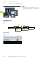
1
Operator Interface
Pushbuttons and Pilot Devices
4.1
Pushbutton and Pilot Devices
Product Overview . . . . . . . . . . . . . . . . . . . . . . . . . . . . . . . . . . . . . . . .
M22—22.5 mm Modular Pushbutton . . . . . . . . . . . . . . . . . . . . . . . . . .
10250T—30 mm Pushbuttons . . . . . . . . . . . . . . . . . . . . . . . . . . . . . . .
4.2
Stacklights
V9-T4-50
V9-T4-54
V9-T4-55
Operator Interfaces and Programming Software
Product Overview . . . . . . . . . . . . . . . . . . . . . . . . . . . . . . . . . . . . . . . .
ELC-GP Graphics Panel . . . . . . . . . . . . . . . . . . . . . . . . . . . . . . . . . . . .
HMi Operator Interface . . . . . . . . . . . . . . . . . . . . . . . . . . . . . . . . . . . .
XV Operator Interface . . . . . . . . . . . . . . . . . . . . . . . . . . . . . . . . . . . . .
XP Operator Interface . . . . . . . . . . . . . . . . . . . . . . . . . . . . . . . . . . . . .
PanelMate ePro PS Operator Interface . . . . . . . . . . . . . . . . . . . . . . . .
Panel Meters
V9-T4-49
Panel Meters
Product Overview . . . . . . . . . . . . . . . . . . . . . . . . . . . . . . . . . . . . . . . .
Digital Panel Meters . . . . . . . . . . . . . . . . . . . . . . . . . . . . . . . . . . . . . . .
4.4
V9-T4-4
V9-T4-37
Stacklights
Product Overview . . . . . . . . . . . . . . . . . . . . . . . . . . . . . . . . . . . . . . . .
E26 Stacklights . . . . . . . . . . . . . . . . . . . . . . . . . . . . . . . . . . . . . . . . . . .
4.3
V9-T4-2
V9-T4-56
V9-T4-59
V9-T4-60
V9-T4-62
V9-T4-64
V9-T4-66
4
4
4
4
4
4
4
4
4
4
4
4
For our complete product offering, see Volume 7—Logic Control, Operator Interface and
Connectivity Solutions, CA08100008E.
4
4
4
4
Operator Interfaces and
Programming Software
4
4
4
4
4
4
4
4
4
4
4
4
4
4
Volume 9—OEM Product Guide CA08100011E—January 2012 www.eaton.com
V9-T4-1
4.1
Operator Interface
Pushbutton and Pilot Devices
4
Product Overview
4
Pushbuttons and Pilot Devices Selection Guide
4
4
4
4
Description
M22—22.5 mm Modular Pushbuttons
10250T—30 mm Pushbuttons
Page V9-T4-4
Page V9-T4-37
Yes
Ease of Use
4
Mounting nut on operator installation
Yes
4
Mounting adapter installation/removal
Easy
—
Contact block installation
Snaps on mounting adapter
Screw in
4
Contact block/light unit installation/removal
Easy
Easy
Visible actuator indication from rear
Yes
Yes
4
Optional spring cage terminations
Yes
—
Optional quick-connect terminations
Yes
Yes
4
Built-in or separate anti-rotation locking ring installation
Built-in
Built-in
4
Mounting time
Low
Low
Removal time
Low
Low
Yes
—
4
Flexibility and Modularity
4
Field convertible pushbuttons—maintained to momentary
Yes
—
Field convertible selector switches—momentary to maintained
Yes
—
4
Field convertible key selector switches—key removal position
Yes
—
4
Universal voltage range LED light units 1
Yes
—
Stackable contact blocks
Yes
—
Enclosed limit switch contacts 2
Yes
—
Yes
Yes
4
Field convertible pushbuttons—color or inscribed button caps
Safety and Security
4
ISO/EN 13850/EN 418 rated E-stops
4
Safety yellow E-stop enclosures
Yes
—
Secure anti-rotation mounting
Good
Good
4
Self-monitoring contact blocks
Yes, available 4Q 2010
No
4
ASi bus network communications
Yes
—
DeviceNet network communications
—
—
4
PROFIBUS-DP network communications
—
—
4
Low profile design
Yes
—
4
Low power integrated LED illuminated devices
Yes
—
Permanent and wear-resistant markings
Yes
—
4
Square bezel pushbuttons and pilot lights
—
—
Communications
Esthetics and Ergonomics
4
Notes
1 Eaton’s M22 LED light units come in two convenient universal ranges: 12–30 Vac/Vdc and 85–244 Vac.
2 Eaton’s M22 pushbutton, selector switch, and E-stop operators can be attached directly to Eaton’s LS Series miniature limit switches.
4
For our complete product offering, see Volume 7—Logic Control, Operator Interface and Connectivity Solutions, CA08100008E.
4
4
4
V9-T4-2
Volume 9—OEM Product Guide CA08100011E—January 2012 www.eaton.com
Operator Interface
Pushbutton and Pilot Devices
4.1
Pushbuttons and Pilot Devices Selection Guide, continued
4
4
4
M22—22.5 mm Modular Pushbuttons
10250T—30 mm Pushbuttons
4
Positive detent on selector switches
Very good
Fair
4
Ergonomic dome shaped E-stop and palm switches
Yes
—
4
4
Description
Esthetics and Ergonomics
Specialty Operator Types
Acoustic indicators (buzzers)
Yes
—
Double pushbutton operators
Yes
No
Elevator E-stops (with mechanical flag indication)
Yes
—
EMO E-stops
—
No
Four-way pushbutton operators
Yes
—
Joysticks
Yes
—
Potentiometers
Yes
Yes
Reset pushbutton operators
Yes
Yes
Selector pushbutton (roto-push) operators
—
—
Selector switches with key monitoring
—
—
Toggle switches
—
—
4
China Compulsory Certification—CCC (China)
Yes
—
4
Conformité Européenne—CE (Europe)
Yes
Yes
4
4
4
4
4
Standards and Certifications
Canadian Standard Association—CSA (Canada)
Yes
Yes
Gosudarstvennyy Standart Russia—GOST R (Russia)
Yes
—
Underwriter’s Laboratories—UL (United States)
Yes
Yes
American Bureau of Shipping—ABS (United States)
—
—
Bureau Veritas—BV (France)
Yes
—
Det Norske Veritas—DNV (Norway)
Yes
—
Germanischer Lloyd—GL (Germany)
Yes
—
4
4
4
Marine Classification Societies
Lloyd’s Register—LR (United Kingdom)
Yes
—
Polski Regestre Statkow—PRS (Poland)
—
—
Registro Italiano Navale—RINA (Italy)
—
—
Russian Maritime Register of Shipping—RMRS (CIS)
—
—
USB socket bulkhead interface
Yes
—
RJ45 socket bulkhead interface
Yes
—
4
4
4
4
4
Accessories
Padlock attachments for pushbuttons
—
Yes
Padlock attachments for selector switches
—
Yes
Padlock attachments for E-stops
No
—
Protective shrouds for E-stops
Yes
Yes
DIN rail mounting adapter
Yes
—
4
4
4
4
For our complete product offering, see Volume 7—Logic Control, Operator Interface and Connectivity Solutions, CA08100008E.
4
4
4
4
Volume 9—OEM Product Guide CA08100011E—January 2012 www.eaton.com
V9-T4-3
4.1
4
Operator Interface
Pushbutton and Pilot Devices
M22—22.5 mm Modular Pushbutton
Features
Highly modular and versatile line
●
Field convertible functions (pushbuttons and selector
switches), maintained to momentary
●
Customizable laser engraving capabilities
4
4
4
LED indicators
●
100,000 hours of life in high-vibration environments
●
Lenses specifically designed for LED illumination
4
Rugged design
●
Most pushbutton operators and contact blocks exceed
5 million mechanical operations
●
All components have IP66 rating, and some carry IP67
and IP69K for washdown environment; see Volume 7—Logic
Control, Operator Interface and Connectivity Solutions,
CA08100008E, Tab 37 for further technical data
4
4
4
4
Innovative technologies
ASi communicating devices
●
Palm switches
4
●
4
Standards and Certifications
4
4
4
4
4
4
4
4
4
4
4
4
4
4
4
4
4
4
4
V9-T4-4
Volume 9—OEM Product Guide CA08100011E—January 2012 www.eaton.com
Operator Interface
Pushbutton and Pilot Devices
4.1
Product Selection
4
Non-Illuminated Pushbuttons, Flush, Momentary
4
Complete Devices
M22-D-G-K10
Bezel
Button Color
Contact Block
Configuration 1
Catalog Number
Silver
Black
NO
M22-D-S-K10
NC
M22-D-S-K01
2NO
M22-D-S-K20
2NC
M22-D-S-K02
Red
Green
M22S-D-G-K10
Black
Black
Red
Green
1NO-1NC
M22-D-S-K11
NO
M22-D-R-K10
NC
M22-D-R-K01
2NO
M22-D-R-K20
2NC
M22-D-R-K02
1NO-1NC
M22-D-R-K11
NO
M22-D-G-K10
NC
M22-D-G-K01
2NO
M22-D-G-K20
2NC
M22-D-G-K02
1NO-1NC
M22-D-G-K11
NO
M22S-D-S-K10
NC
M22S-D-S-K01
2NO
M22S-D-S-K20
2NC
M22S-D-S-K02
1NO-1NC
M22S-D-S-K11
NO
M22S-D-R-K10
NC
M22S-D-R-K01
2NO
M22S-D-R-K20
2NC
M22S-D-R-K02
1NO-1NC
M22S-D-R-K11
NO
M22S-D-G-K10
NC
M22S-D-G-K01
2NO
M22S-D-G-K20
2NC
M22S-D-G-K02
1NO-1NC
M22S-D-G-K11
4
4
4
4
4
4
4
4
4
4
4
4
4
4
4
4
4
4
Note
1 All NC contact blocks are positively driven contact.
4
4
4
4
4
4
4
4
4
4
Volume 9—OEM Product Guide CA08100011E—January 2012 www.eaton.com
V9-T4-5
4.1
Operator Interface
Pushbutton and Pilot Devices
4
Non-Illuminated Pushbuttons, Flush
4
Components
4
M22-XD-G
4
Momentary Buttonless Operator
Button Plates 1
Color
Black
Inscription
Bezel
Catalog Number 4
M22-D-X
Silver
M22-D-X
M22S-D-X
Black
M22S-D-X
M22-DG-X
Silver guarded
M22-DG-X
Catalog Number
2
—
M22-XD-S
Custom
M22-XD-S-ETCH 3
4
STOP
M22-XD-S-GB0
4
START
M22-XD-S-GB1
CLOSE
M22-XD-S-GB2
4
UP
M22-XD-S-GB3
DOWN
M22-XD-S-GB4
4
OFF
M22-XD-S-GB5
4
ON
M22-XD-S-GB6
TEST
M22-XD-S-GB9
4
FORWARD
M22-XD-S-GB15
REVERSE
M22-XD-S-GB16
4
RAISE
M22-XD-S-GB17
LOWER
M22-XD-S-GB18
4
M22-XD-S-X0
4
M22-XD-S-X2
M22-XD-S-X1
4
M22-XD-S-X4
4
M22-XD-S-X7
Maintained Buttonless Operator 5
M22-XD-S-X5
—
M22-XD-R 2
4
Custom
M22-XD-R-ETCH 3
4
STOP
M22-XD-R-GB0
OFF
M22-XD-R-GB5
Red
M22-XD-R-X0
4
—
M22-XD-G 2
4
Custom
M22-XD-G-ETCH 3
M22-XD-G-GB1
4
START
ON
M22-XD-G-GB6
Green
Bezel
Catalog Number 4
M22-DR-X
Silver
M22-DR-X
M22S-DR-X
Black
M22S-DR-X
M22-XD-G-X1
4
Blue
4
4
—
M22-XD-B 2
Custom
M22-XD-B-ETCH 3
RESET
M22-XD-B-GB14
M22-XD-B-X6
White
4
4
—
M22-XD-W 2
Custom
M22-XD-W-ETCH 3
START
M22-XD-W-GB1
M22-XD-W-X1
4
Yellow
4
4
—
M22-XD-Y 2
Custom
M22-XD-Y-ETCH 3
Black, red, green —
M22-XD-SRG
Black, white,
red, green,
yellow, blue
M22-XD-SWRGYB
—
Notes
1 For complete listing of available button plates and contact blocks, see Accessories,
Pages V9-T4-31 to V9-T4-36.
2 Minimum order quantity of (10).
3 When ordering, specify inscription per catalog number suffix from the Symbols Library
(see Volume 7—Logic Control, Operator Interface and Connectivity Solutions, CA08100008E,
Tab 37) into the Order Notes.
For example, M22-XD-S-ETCH; Order Notes: Mark with symbol X91, Line item #_.
4 Includes contact block mounting adapter.
5 Maintained pushbuttons can be converted in the field to momentary operation by switching
the locking ring, which is accessible through the side of the operator body.
4
4
V9-T4-6
Volume 9—OEM Product Guide CA08100011E—January 2012 www.eaton.com
Operator Interface
Pushbutton and Pilot Devices
4.1
Non-Illuminated Pushbuttons, Extended, Momentary
4
Complete Devices
M22-DH-R-K10
M22S-DH-R-K10
M22-DGH-R-K10
Bezel
Button Color
Silver
Red
Black
Silver guarded
Red
Red
Contact Block
Configuration 1
Catalog Number
NO
M22-DH-R-K10
NC
M22-DH-R-K01
2NO
M22-DH-R-K20
2NC
M22-DH-R-K02
1NO-1NC
M22-DH-R-K11
NO
M22S-DH-R-K10
NC
M22S-DH-R-K01
2NO
M22S-DH-R-K20
2NC
M22S-DH-R-K02
1NO-1NC
M22S-DH-R-K11
NO
M22-DGH-R-K10
NC
M22-DGH-R-K01
2NO
M22-DGH-R-K20
2NC
M22-DGH-R-K02
1NO-1NC
M22-DGH-R-K11
4
4
4
4
4
4
4
4
4
4
4
Note
1 All NC contact blocks are positively driven contact.
4
4
4
4
4
4
4
4
4
4
4
4
4
4
4
4
4
4
Volume 9—OEM Product Guide CA08100011E—January 2012 www.eaton.com
V9-T4-7
4.1
Operator Interface
Pushbutton and Pilot Devices
4
Non-Illuminated Pushbuttons, Extended
4
Components
4
M22-XDH-R
Momentary Buttonless Operator
Button Plates 1
Color
Black
Inscription
2
—
M22-XDH-S
Custom
M22-XDH-S-ETCH 3
STOP
M22-XDH-S-GB0
START
M22-XDH-S-GB1
4
CLOSE
M22-XDH-S-GB2
4
UP
M22-XDH-S-GB3
DOWN
M22-XDH-S-GB4
4
OFF
M22-XDH-S-GB5
ON
M22-XDH-S-GB6
4
TEST
M22-XDH-S-GB9
4
FORWARD
M22-XDH-S-GB15
REVERSE
M22-XDH-S-GB16
RAISE
M22-XDH-S-GB17
LOWER
M22-XDH-S-GB18
4
4
4
4
Bezel
Catalog Number 4
M22-D-X
Silver
M22-D-X
M22S-D-X
Black
M22S-D-X
M22-DG-X
Silver guarded
M22-DG-X
Catalog Number
M22-XDH-S-X0
M22-XDH-S-X1
4
M22-XDH-S-X2
4
M22-XDH-S-X4
Maintained Buttonless Operator 5
M22-XDH-S-X5
Bezel
Catalog Number 4
M22-DR-X
Silver
M22-DR-X
M22S-DR-X
Black
M22S-DR-X
M22-XDH-S-X7
4
Red
4
4
—
M22-XDH-R 2
Custom
M22-XDH-R-ETCH 3
STOP
M22-XDH-R-GB0
OFF
M22-XDH-R-GB5
M22-XDH-R-X0
4
—
M22-XDH-G 2
4
Custom
M22-XDH-G-ETCH 3
START
M22-XDH-G-GB1
4
ON
M22-XDH-G-GB6
Green
M22-XDH-G-X1
4
Blue
4
4
—
M22-XDH-B 2
Custom
M22-XDH-B-ETCH 3
RESET
M22-XDH-B-GB14
—
M22-XDH-W 2
Custom
M22-XDH-W-ETCH 3
START
M22-XDH-W-GB1
M22-XDH-B-X6
White
4
4
M22-XDH-W-X1
4
Yellow
4
Black, red, green
—
M22-XDH-Y 2
Custom
M22-XDH-Y-ETCH 3
—
M22-XDH-SRG
Black, white, red, —
green, yellow, blue
4
Notes
1 For complete listing of available button plates and contact blocks, see Accessories,
Pages V9-T4-31 to V9-T4-36.
2 Minimum order quantity of (10).
3 When ordering, specify inscription per catalog number suffix from the Symbols Library
(see Volume 7—Logic Control, Operator Interface and Connectivity Solutions, CA08100008E,
Tab 37) into the Order Notes.
For example, M22-XDH-S-ETCH; Order Notes: Mark with symbol X91, Line item #_.
4 Includes contact block mounting adapter.
5 Maintained pushbuttons can be converted in the field to momentary operation by switching
the locking ring, which is accessible through the side of the operator body.
M22-XDH-SWRGYB
4
4
V9-T4-8
Volume 9—OEM Product Guide CA08100011E—January 2012 www.eaton.com
4.1
Operator Interface
Pushbutton and Pilot Devices
Illuminated Pushbuttons, Flush, Momentary
4
Complete Devices
M22-DL-G-K01-G
Bezel
Button Color
Contact Block
Configuration 1
Light Unit Voltage
Catalog Number
Silver
Red
NC
12–30 Vac/Vdc
M22-DL-R-K01-R
NC
85–264 Vac
M22-DL-R-K01-230R
2NC
12–30 Vac/Vdc
M22-DL-R-K02-R
2NC
85–264 Vac
M22-DL-R-K02-230R
1NO/1NC
12–30 Vac/Vdc
M22-DL-R-K11-R
1NO/1NC
85–264 Vac
M22-DL-R-K11-230R
NO
12–30 Vac/Vdc
M22-DL-G-K10-G
NO
85–264 Vac
M22-DL-G-K10-230G
2NO
12–30 Vac/Vdc
M22-DL-G-K20-G
2NO
85–264 Vac
M22-DL-G-K20-230G
Green
White
M22S-DL-G-K01-G
Black
Red
Green
White
1NO/1NC
12–30 Vac/Vdc
M22-DL-G-K11-G
1NO/1NC
85–264 Vac
M22-DL-G-K11-230G
4
4
4
4
4
4
4
4
4
NO
12–30 Vac/Vdc
M22-DL-W-K10-W
NO
85–264 Vac
M22-DL-W-K10-230W
2NO
12–30 Vac/Vdc
M22-DL-W-K20-W
2NO
85–264 Vac
M22-DL-W-K20-230W
1NO/1NC
12–30 Vac/Vdc
M22-DL-W-K11-W
1NO/1NC
85–264 Vac
M22-DL-W-K11-230W
NC
12–30 Vac/Vdc
M22S-DL-R-K01-R
NC
85–264 Vac
M22S-DL-R-K01-230R
2NC
12–30 Vac/Vdc
M22S-DL-R-K02-R
2NC
85–264 Vac
M22S-DL-R-K02-230R
1NO/1NC
12–30 Vac/Vdc
M22S-DL-R-K11-R
1NO/1NC
85–264 Vac
M22S-DL-R-K11-230R
NO
12–30 Vac/Vdc
M22S-DL-G-K10-G
NO
85–264 Vac
M22S-DL-G-K10-230G
2NO
12–30 Vac/Vdc
M22S-DL-G-K20-G
2NO
85–264 Vac
M22S-DL-G-K20-230G
1NO/1NC
12–30 Vac/Vdc
M22S-DL-G-K11-G
1NO/1NC
85–264 Vac
M22S-DL-G-K11-230G
NO
12–30 Vac/Vdc
M22S-DL-W-K10-W
NO
85–264 Vac
M22S-DL-W-K10-230W
2NO
12–30 Vac/Vdc
M22S-DL-W-K20-W
2NO
85–264 Vac
M22S-DL-W-K20-230W
1NO/1NC
12–30 Vac/Vdc
M22S-DL-W-K11-W
1NO/1NC
85–264 Vac
M22S-DL-W-K11-230W
4
4
4
4
4
4
4
4
4
4
4
4
4
4
Note
1 All NC contact blocks are positively driven contact.
4
4
4
4
4
4
Volume 9—OEM Product Guide CA08100011E—January 2012 www.eaton.com
V9-T4-9
4.1
Operator Interface
Pushbutton and Pilot Devices
4
Illuminated Pushbuttons, Flush
4
Components
4
M22-XDL-G
4
Momentary Buttonless Operator
Button Lenses 1
Color
Red
4
4
Inscription
Bezel
Catalog Number 4
M22-DL-X
Silver
M22-DL-X
M22S-DL-X
Black
M22S-DL-X
M22-DGL-X
Silver guarded
M22-DGL-X
Catalog Number
2
—
M22-XDL-R
Custom
M22-XDL-R-ETCH 3
STOP
M22-XDL-R-GB0
OFF
M22-XDL-R-GB5
M22-XDL-R-X0
Green
4
4
4
—
M22-XDL-G 2
Custom
M22-XDL-G-ETCH 3
START
M22-XDL-G-GB1
ON
M22-XDL-G-GB6
M22-XDL-G-X1
Blue
4
4
—
M22-XDL-B 2
Custom
M22-XDL-B-ETCH 3
RESET
M22-XDL-B-GB14
—
M22-XDL-W 2
Custom
M22-XDL-W-ETCH 3
—
M22-XDL-Y 2
Custom
M22-XDL-Y-ETCH 3
M22-XDL-B-X6
4
White
4
Yellow
4
4
Maintained Buttonless Operator 5
Bezel
Catalog Number 4
M22-DRL-X
Silver
M22-DRL-X
M22S-DRL-X
Black
M22S-DRL-X
4
4
4
4
4
4
Notes
1 For complete listing of available button plates and contact blocks, see Accessories,
Pages V9-T4-31 to V9-T4-36.
2 Minimum order quantity of (10).
3 When ordering, specify inscription per catalog number suffix from the Symbols Library
(see Volume 7—Logic Control, Operator Interface and Connectivity Solutions, CA08100008E,
Tab 37) into the Order Notes.
For example, M22-XDL-R-ETCH; Order Notes: Mark with symbol X91, Line item #_.
4 Includes contact block mounting adapter.
5 Maintained pushbuttons can be converted in the field to momentary operation by switching
the locking ring, which is accessible through the side of the operator body.
4
4
4
4
4
4
4
4
4
V9-T4-10
Volume 9—OEM Product Guide CA08100011E—January 2012 www.eaton.com
4.1
Operator Interface
Pushbutton and Pilot Devices
Illuminated Pushbuttons, Extended, Momentary
4
Complete Devices
M22-DLH-R-K11-R
Bezel
Button Color
Light Unit Voltage
Catalog Number
Silver
Red
1NO/1NC
12–30 Vac/Vdc
M22-DLH-R-K11-R
1NO/1NC
85–264 Vac
M22-DLH-R-K11-230R
2NO
12–30 Vac/Vdc
M22-DLH-G-K20-G
2NO
85–264 Vac
M22-DLH-G-K20-230G
2NO
12–30 Vac/Vdc
M22-DLH-W-K20-W
2NO
85–264 Vac
M22-DLH-W-K20-230W
Green
White
M22S-DLH-R-K11-R
4
Contact Block
Configuration 1
Black
Red
Green
White
4
1NO/1NC
12–30 Vac/Vdc
M22S-DLH-R-K11-R
1NO/1NC
85–264 Vac
M22S-DLH-R-K11-230R
2NO
12–30 Vac/Vdc
M22S-DLH-G-K20-G
2NO
85–264 Vac
M22S-DLH-G-K20-230G
2NO
12–30 Vac/Vdc
M22S-DLH-W-K20-W
2NO
85–264 Vac
M22S-DLH-W-K20-230W
Note
1 All NC contact blocks are positively driven contact.
4
4
4
4
4
4
4
4
4
4
4
4
4
4
4
4
4
4
4
4
4
4
4
4
4
4
4
Volume 9—OEM Product Guide CA08100011E—January 2012 www.eaton.com
V9-T4-11
4.1
Operator Interface
Pushbutton and Pilot Devices
4
Illuminated Pushbuttons, Extended
4
Components
4
M22-XDH-R
4
Momentary Buttonless Operator
Button Lenses 1
Color
Red
4
4
Inscription
Bezel
Catalog Number 4
M22-DL-X
Silver
M22-DL-X
M22S-DL-X
Black
M22S-DL-X
M22-DGL-X
Silver guarded
M22-DGL-X
Catalog Number
2
—
M22-XDLH-R
Custom
M22-XDLH-R-ETCH 3
STOP
M22-XDLH-R-GB0
OFF
M22-XDLH-R-GB5
M22-XDLH-R-X0
Green
4
4
4
—
M22-XDLH-G 2
Custom
M22-XDLH-G-ETCH 3
START
M22-XDLH-G-GB1
ON
M22-XDLH-G-GB6
M22-XDLH-G-X1
Blue
4
4
—
M22-XDLH-B 2
Custom
M22-XDLH-B-ETCH 3
RESET
M22-XDLH-B-GB14
M22-XDLH-B-X6
4
White
4
Yellow
4
4
—
M22-XDLH-W 2
Custom
M22-XDLH-W-ETCH 3
—
M22-XDLH-Y 2
Custom
M22-XDLH-Y-ETCH 3
Maintained Buttonless Operator 5
Bezel
Catalog Number 4
M22-DRL-X
Silver
M22-DRL-X
M22S-DRL-X
Black
M22S-DRL-X
4
4
4
4
4
4
Notes
1 For complete listing of available button plates and contact blocks, see Accessories,
Pages V9-T4-31 to V9-T4-36.
2 Minimum order quantity of (10).
3 When ordering, specify inscription per catalog number suffix from the Symbols Library
(see Volume 7—Logic Control, Operator Interface and Connectivity Solutions, CA08100008E,
Tab 37) into the Order Notes.
For example, M22-XDH-S-ETCH; Order Notes: Mark with symbol X91, Line item #_.
4 Includes contact block mounting adapter.
5 Maintained pushbuttons can be converted in the field to momentary operation by switching
the locking ring, which is accessible through the side of the operator body.
4
4
4
4
4
4
4
4
4
V9-T4-12
Volume 9—OEM Product Guide CA08100011E—January 2012 www.eaton.com
Operator Interface
Pushbutton and Pilot Devices
4.1
Indicating Lights, Flush
M22-L-R-R
Lens Color
M22S-DLH-R-K11-R
4
Complete Devices
Light Color
Light Unit Voltage
Catalog Number
White
White
12–30 Vac/Vdc
M22-L-W-W
Red
Red
M22-L-R-R
Green
Green
M22-L-G-G
Yellow
White
M22-L-Y-W
Blue
Blue
M22-L-B-B
Amber
White
M22-L-A-W
White
White
Red
Red
M22-L-R-230R
Green
Green
M22-L-G-230G
Yellow
White
M22-L-Y-230W
Blue
Blue
M22-L-B-230B
Amber
White
M22-L-A-230W
85–264 Vac
4
4
4
4
4
M22-L-W-230W
4
4
4
4
Complete Press-to-Test Units
Bezel
Button Color
Light Unit Voltage
Catalog Number
Silver
Red
12–30 Vac/Vdc
M22-T-R-R
Blue
M22-T-B-B
Yellow
M22-T-Y-W
Green
M22-T-G-G
White
Red
M22-T-R-230B
Yellow
M22-T-Y-230W
Green
M22-T-G-230G
4
4
4
4
M22-T-W-230W
12–30 Vac/Vdc
M22S-T-R-R
Blue
M22S-T-B-B
Yellow
M22S-T-Y-W
Green
M22S-T-G-G
White
M22S-T-W-W
Red
4
M22-T-R-230R
Blue
Red
4
M22-T-W-W
85–264 Vac
White
Black
4
85–264 Vac
4
4
4
M22S-T-R-230R
Blue
M22S-T-B-230B
Yellow
M22S-T-Y-230W
Green
M22S-T-G-230G
White
M22S-T-W-230W
4
4
4
4
4
4
4
4
4
4
Volume 9—OEM Product Guide CA08100011E—January 2012 www.eaton.com
V9-T4-13
4.1
4
Components
4
M22-XL-R
4
4
Operator Interface
Pushbutton and Pilot Devices
Lenses 1
Color
Inscription
Catalog Number
Red
—
M22-XL-R 2
Custom
M22-XL-R-ETCH 3
OFF
M22-XL-R-GB5
—
M22-XL-G 2
4
Custom
M22-XL-G-ETCH 3
4
ON
M22-XL-G-GB6
REVERSE
M22-XL-G-GB16
—
M22-XL-B 2
Custom
M22-XL-B-ETCH 3
FAULT
M22-XL-B-GB8
—
M22-XL-W 2
Custom
M22-XL-W-ETCH 3
OFF
M22-XL-W-GB5
4
ON
M22-XL-W-GB6
4
FAULT
M22-XL-W-GB8
FORWARD
M22-XL-W-GB15
—
M22-XL-Y 2
Custom
M22-XL-Y-ETCH 3
—
M22-XL-A 2
Custom
M22-XL-A-ETCH 3
Green
Blue
4
4
White
4
4
Yellow
4
Amber
4
4
M22-L-X
Lensless Indicating Light
Catalog Number
4
M22-L-X
4
4
Notes
1 For complete listing of available lenses and light units, see Accessories, Pages V9-T4-31 to V9-T4-36.
2 Minimum order quantity of (10).
3 When ordering, specify inscription per catalog number suffix from the Symbols Library (see Volume 7—
Logic Control, Operator Interface and Connectivity Solutions, CA08100008E, Tab 37) into the Order Notes.
For example, M22-XL-R-ETCH; Order Notes: Mark with symbol X91, Line item #_.
4
4
4
4
4
4
4
4
4
4
4
4
V9-T4-14
Volume 9—OEM Product Guide CA08100011E—January 2012 www.eaton.com
Operator Interface
Pushbutton and Pilot Devices
4.1
Non-Illuminated Emergency Stops
M22-PV-K01
4
Complete Devices
Type
Color
Push-pull
Red
Twist-to-release
Key release
Red
Red
Contact Block
Configuration 1
Catalog Number
NC
M22-PV-K01
2NC
M22-PV-K02
1NO-2NC
M22-PV-K12
NC
M22-PVT-K01
2NC
M22-PVT-K02
1NO-2NC
M22-PVT-K12
NC
M22-PVS-K01
2NC
M22-PVS-K02
1NO-2NC
M22-PVS-K12
4
4
4
4
4
4
4
4
Components
4
Operators Only 2
M22-PV
Type
Color
Catalog Number
Push-pull
Red
M22-PV
Black
M22S-PV
4
4
4
4
M22S-PVT
Twist-torelease
Red
M22-PVT
Black
M22S-PVT
4
4
4
Key release 3
Red
4
M22-PVS 4
M22-PVS-MS2
4
M22-PVS-MS3
M22-PVS-MS4
4
M22-PVS-MS5
4
M22-PVS-MS6
M22-PVS-MS7
4
M22-PVS-MS8
Notes
1 All NC contact blocks are positively driven contact.
2 Includes contact block mounting adapter.
3 Key included. For identical locks and keys, use the same key code. One key is included with actuator;
additional keys are available as accessories.
4 Includes Key Code MS1.
4
4
4
4
4
4
4
4
Volume 9—OEM Product Guide CA08100011E—January 2012 www.eaton.com
V9-T4-15
4.1
Operator Interface
Pushbutton and Pilot Devices
4
Illuminated Emergency Stops
4
M22-PVL-K01-R
4
Complete Devices
Type
Button Color
LED Color
Push-pull
Red
Red
Contact Block
Configuration 1
Light Unit Voltage
Catalog Number
NC
12–30 Vac/Vdc
M22-PVL-K01-R
4
2NC
12–30 Vac/Vdc
M22-PVL-K02-R
1NO-2NC
12–30 Vac/Vdc
M22-PVL-K12-R
4
NC
85–264 Vac
M22-PVL-K01-230R
2NC
85–264 Vac
M22-PVL-K02-230R
1NO-2NC
85–264 Vac
M22-PVL-K12-230R
NC
12–30 Vac/Vdc
M22-PVLT-K01-R
2NC
12–30 Vac/Vdc
M22-PVLT-K02-R
4
1NO-2NC
12–30 Vac/Vdc
M22-PVLT-K12-R
NC
85–264 Vac
M22-PVLT-K01-230R
4
2NC
85–264 Vac
M22-PVLT-K02-230R
1NO-2NC
85–264 Vac
M22-PVLT-K12-230R
4
Twist-to-release
4
4
4
Components
Operators Only 2
4
4
M22-PVL
Type
Color
Catalog Number
Push-pull
Red
M22-PVL
Black
M22S-PVL
Red
M22-PVLT
Black
M22S-PVLT
4
4
4
M22S-PVLT
4
Twist-to- release
4
4
Notes
1 All NC contact blocks are positively driven contact.
2 Includes contact block mounting adapter.
4
4
4
4
4
4
4
4
4
4
4
V9-T4-16
Volume 9—OEM Product Guide CA08100011E—January 2012 www.eaton.com
Operator Interface
Pushbutton and Pilot Devices
4.1
Non-Illuminated Selector Switches
M22-WKV-K10
4
Complete Devices, Knob Type 1
Type
Switching Position
Bezel
Contact Block
Configuration 2
Catalog Number
Two-position
Maintained
Silver
NO
M22-WRK-K10
1NO-1NC
M22-WRK-K11
2NO-2NC
M22-WRK-K22
NO
M22S-WRK-K10
1NO-1NC
M22S-WRK-K11
2NO-2NC
M22S-WRK-K22
NO
M22-WKV-K10
1NO-1NC
M22-WKV-K11
Black
Maintained V
Silver
Black
Three-position
Maintained
Silver
Black
2NO-2NC
M22-WKV-K22
NO
M22S-WKV-K10
1NO-1NC
M22S-WKV-K11
2NO-2NC
M22S-WKV-K22
2NO
M22-WRK3-K20
2NO-2NC
M22-WRK3-K22
2NO
M22S-WRK3-K20
2NO-2NC
M22S-WRK3-K22
4
4
4
4
4
4
4
4
4
4
4
Notes
1 Includes contact block mounting adapter.
2 All NC contact blocks are positively driven contact.
4
4
4
4
4
4
4
4
4
4
4
4
4
4
4
4
4
4
Volume 9—OEM Product Guide CA08100011E—January 2012 www.eaton.com
V9-T4-17
4.1
Operator Interface
Pushbutton and Pilot Devices
4
Non-Illuminated Selector Switches, continued
4
Components
4
M22-WK
4
Operators Only, Knob Type 1
Type
Switching Position
Bezel
Catalog Number
Two-position
Momentary 2
Silver
M22-WK
Black
M22S-WK
Silver
M22-WRK
Black
M22S-WRK
4
Maintained
4
4
Maintained V
4
4
Three-position
Momentary 2
4
4
Maintained
4
4
Maintained, return from left
4
4
Maintained, return from right
4
4
Four-position
Maintained
Silver
M22-WKV
Black
M22S-WKV
Silver
M22-WK3
Black
M22S-WK3
Silver
M22-WRK3
Black
M22S-WRK3
Silver
M22-WRK3-2
Black
M22S-WRK3-2
Silver
M22-WRK3-1
Black
M22S-WRK3-1
Silver
M22-WRK4
Black
M22S-WRK4
4
4
Notes
1 Includes contact block mounting adapter.
2 Momentary selector switches can be converted in the field to maintained operation with the removal of a color
coded adapter. See Volume 7—Logic Control, Operator Interface and Connectivity Solutions, CA08100008E, Tab 37.
4
4
4
4
4
4
4
4
4
4
4
V9-T4-18
Volume 9—OEM Product Guide CA08100011E—January 2012 www.eaton.com
Operator Interface
Pushbutton and Pilot Devices
4.1
Non-Illuminated Selector Switches, continued
4
Components
4
M22S-WR3-X94
Operators Only, Rotary Type 1
Type
Switching Position
Bezel
Inscription
Catalog Number
Two-position
Momentary 2
Silver
I-O
M22-W
Black
I-O
M22S-W
Silver
I-O
M22-WR
Custom
M22-WR-ETCH 3
AUTO-HAND
M22-WR-X91
II-I
M22-WR-X92
I-O
M22S-WR
Custom
M22S-WR-ETCH 3
AUTO-HAND
M22S-WR-X91
4
4
4
Maintained
Black
Three-position
Momentary 2
Maintained
II-I
M22S-WR-X92
Silver
I-O-II
M22-W3
Black
I-O-II
M22S-W3
Silver
I-O-II
M22-WR3
Custom
M22-WR3-ETCH 3
AUTO-O-MAN
M22-WR3-X94
I-O-II
M22S-WR3
Custom
M22S-WR3-ETCH 3
Black
Four-position
Maintained
AUTO-O-MAN
M22S-WR3-X94
Silver
0-1-0-2-0-3-0-4
M22-WR4
Black
0-1-0-2-0-3-0-4
M22S-WR4
4
4
4
4
4
4
4
4
4
4
4
4
4
Notes
1 Includes contact block mounting adapter.
2 Momentary selector switches can be converted in the field to maintained operation with the removal of a color
coded adapter. See Volume 7—Logic Control, Operator Interface and Connectivity Solutions, CA08100008E, Tab 37.
3 When ordering, specify inscription per catalog number suffix from the Symbols Library (see Volume 7—
Logic Control, Operator Interface and Connectivity Solutions, CA08100008E, Tab 37) into the Order Notes.
For example, M22-WR3-ETCH; Order Notes: Mark with symbol X88, Line item #_.
4
4
4
4
4
4
4
4
4
4
4
4
Volume 9—OEM Product Guide CA08100011E—January 2012 www.eaton.com
V9-T4-19
4.1
Operator Interface
Pushbutton and Pilot Devices
4
Illuminated Selector Switches
4
Components
4
M22-WLK-W
Operators Only, Knob Type 1
Type
4
Switching Position
2
Bezel
Catalog Number
White
M22-WLK-W
Red
M22-WLK-R
4
Green
M22-WLK-G
4
Yellow
M22-WLK-Y
Blue
M22-WLK-B
White
M22S-WLK-W
Red
M22S-WLK-R
4
Green
M22S-WLK-G
4
Yellow
M22S-WLK-Y
Blue
M22S-WLK-B
White
M22-WRLK-W
Red
M22-WRLK-R
Green
M22-WRLK-G
Yellow
M22-WRLK-Y
Blue
M22-WRLK-B
White
M22S-WRLK-W
Red
M22S-WRLK-R
4
Green
M22S-WRLK-G
Yellow
M22S-WRLK-Y
4
Blue
M22S-WRLK-B
White
M22-WLKV-W
4
Red
M22-WLKV-R
4
Green
M22-WLKV-G
Yellow
M22-WLKV-Y
Blue
M22-WLKV-B
White
M22S-WLKV-W
4
Red
M22S-WLKV-R
M22S-WLKV-G
4
Green
Yellow
M22S-WLKV-Y
Blue
M22S-WLKV-B
Two-position
Momentary
Silver
Button Color
Black
4
Maintained
4
Silver
4
4
Black
4
Maintained V
4
Silver
Black
4
Notes
1 Includes contact block mounting adapter.
2 Momentary selector switches can be converted in the field to maintained operation with the removal of a color coded
adapter. See Volume 7—Logic Control, Operator Interface and Connectivity Solutions, CA08100008E, Tab 37.
4
4
4
4
4
4
4
4
4
V9-T4-20
Volume 9—OEM Product Guide CA08100011E—January 2012 www.eaton.com
Operator Interface
Pushbutton and Pilot Devices
4.1
Illuminated Selector Switches, continued
4
Components
4
M22-WLK3-W
Operators Only, Knob Type 1
Type
Switching Position
Bezel
Button Color
Catalog Number
Three-position
Momentary 2
Silver
White
M22-WLK3-W
Red
M22-WLK3-R
Green
M22-WLK3-G
Yellow
M22-WLK3-Y
Blue
M22-WLK3-B
White
M22S-WLK3-W
Red
M22S-WLK3-R
Green
M22S-WLK3-G
Yellow
M22S-WLK3-Y
Blue
M22S-WLK3-B
White
M22-WRLK3-W
Red
M22-WRLK3-R
Green
M22-WRLK3-G
Yellow
M22-WRLK3-Y
Blue
M22-WRLK3-B
White
M22S-WRLK3-W
Red
M22S-WRLK3-R
Green
M22S-WRLK3-G
Yellow
M22S-WRLK3-Y
Blue
M22S-WRLK3-B
White
M22-WRLK3-1-W
Red
M22-WRLK3-1-R
Green
M22-WRLK3-1-G
Yellow
M22-WRLK3-1-Y
Blue
M22-WRLK3-1-B
White
M22S-WRLK3-1-W
Red
M22S-WRLK3-1-R
Green
M22S-WRLK3-1-G
Yellow
M22S-WRLK3-1-Y
Blue
M22S-WRLK3-1-B
Black
Maintained
Silver
Black
Maintained, return from right
Silver
Black
Maintained, return from left
Silver
Black
White
M22-WRLK3-2-W
Red
M22-WRLK3-2-R
Green
M22-WRLK3-2-G
Yellow
M22-WRLK3-2-Y
Blue
M22-WRLK3-2-B
White
M22S-WRLK3-2-W
Red
M22S-WRLK3-2-R
Green
M22S-WRLK3-2-G
Yellow
M22S-WRLK3-2-Y
Blue
M22S-WRLK3-2-B
4
4
4
4
4
4
4
4
4
4
4
4
4
4
4
4
4
4
4
4
4
4
4
4
4
Notes
1 Includes contact block mounting adapter.
2 Momentary selector switches can be converted in the field to maintained operation with the removal of a color coded
adapter. See Volume 7—Logic Control, Operator Interface and Connectivity Solutions, CA08100008E, Tab 37.
4
4
4
Volume 9—OEM Product Guide CA08100011E—January 2012 www.eaton.com
V9-T4-21
4.1
4
4
Pushbutton and Pilot Devices
Key-Operated Selector Switches 12
For additional key code options, see Volume 7—Solid-State Motor Control, CA08100008E, Tab 37.
Components
4
4
Operator Interface
Operators Only 3
M22-WS
Type
Switching Position
Key Code
Bezel
Key Removal Position
Catalog Number
Two-position
Momentary
MS1
Silver
Return from right, key
removable left
M22-WS
Black
Return from right, key
removable left
M22S-WS
MS1
Silver
Key removable left
M22-WRS-A1
Key removable left/right
M22-WRS
MS1
Black
Key removable left
M22S-WRS-A1
Key removable left/right
M22S-WRS
Silver
Return from left/right,
key removable center
M22-WS3
Black
Return from left/right,
key removable center
M22S-WS3
4
4
4
4
4
M22S-WRS
Two-position
Maintained
4
4
4
M22-WS3-X93
Three-position
Momentary 4
MS1
4
Maintained
Key removable center
M22-WRS3-A1
Key removable
center/left
M22-WRS3-A2
Key removable
center/right
M22-WRS3-A3
Key removable left/right
M22-WRS3
4
Return from left,
key removable center
M22-WRS3-A7
4
Return from left,
key removable center/right
M22-WRS3-A6
4
Return from right,
key removable left/center
M22-WRS3-A4
4
Return from right,
key removable center
M22-WRS3-A5
4
MS1
Silver
4
4
Black
Key removable center
M22S-WRS3-A1
Key removable
center/left
M22S-WRS3-A2
Key removable
center/right
M22S-WRS3-A3
Key removable
left/right/center
M22S-WRS3
Return from left,
key removable center
M22S-WRS3-A7
4
Return from left,
key removable center/right
M22S-WRS3-A6
4
Return from right,
key removable left/center
M22S-WRS3-A4
4
Return from right,
key removable center
M22S-WRS3-A5
4
4
4
4
Black
4
Notes
1 Includes one key.
2 Key removal positions can be modified in the field using coding adapters; see Volume 7—Logic Control, Operator Interface and Connectivity Solutions, CA08100008E,
Tab 37.
3 Includes contact block mounting adapter.
4 Momentary selector switches can be converted in the field to maintained operation with the removal of a color coded adapter. See Volume 7—Logic Control, Operator
Interface and Connectivity Solutions CA08100008E, Tab 37.
4
4
4
V9-T4-22
Volume 9—OEM Product Guide CA08100011E—January 2012 www.eaton.com
Operator Interface
Pushbutton and Pilot Devices
4.1
Mushroom Head Pushbuttons 1
4
Momentary Complete Devices
M22-DP-R-K01
M22S-DP-R-K01
Bezel
Button Color
Silver
Red
Black
Red
Contact Block
Configuration
2
4
Catalog Number
NC
M22-DP-R-K01
2NC
M22-DP-R-K02
1NO-2NC
M22-DP-R-K12
1NO-1NC
M22-DP-R-K11
NC
M22S-DP-R-K01
2NC
M22S-DP-R-K02
1NO-2NC
M22S-DP-R-K12
1NO-1NC
M22S-DP-R-K11
4
4
4
4
4
4
4
Non-Illuminated Mushroom Head Pushbuttons, Maintained
4
1 3
Complete Devices
M22-DP-R-K01
M22S-DP-R-K01
Bezel
Button Color
Silver
Red
Black
Red
Contact Block
Configuration
4
4
Catalog Number
NC
M22-DRP-R-K01
2NC
M22-DRP-R-K02
1NO-2NC
M22-DRP-R-K12
1NO-1NC
M22-DRP-R-K11
NC
M22S-DRP-R-K01
2NC
M22S-DRP-R-K02
1NO-2NC
M22S-DRP-R-K12
1NO-1NC
M22S-DRP-R-K11
4
4
4
4
4
4
4
Notes
1 35 mm diameter mushroom head button.
2 Includes contact block mounting adapter.
3 Maintained pushbuttons can be converted in the field to momentary operation by switching the locking ring,
which is accessible through the side of the operator body.
4 All NC contact blocks are positively driven contact.
4
4
4
4
4
4
4
4
4
4
4
4
Volume 9—OEM Product Guide CA08100011E—January 2012 www.eaton.com
V9-T4-23
4.1
Operator Interface
Pushbutton and Pilot Devices
4
Non-Illuminated Mushroom Head Pushbuttons 1
4
Components
4
M22-XDP-G
Mushroom Head Plates
M22-DP-G-X
Momentary Insertless Mushroom Head
Operators
Color
Inscription
Catalog Number
Black
-—
M22-XDP-S 2
Bezel
Custom
M22-XDP-S-ETCH 3
Silver
4
STOP
M22-XDP-S-GB0
M22-XDP-S-GB1
Green
M22-DP-G-X
4
START
FORWARD
M22-XDP-S-GB15
Yellow
M22-DP-Y-X
REVERSE
M22-XDP-S-GB16
Black
M22S-DP-S-X
UP
M22-XDP-S-GB3
Red
M22S-DP-R-X
4
DOWN
M22-XDP-S-GB4
Green
M22S-DP-G-X
OFF
M22-XDP-S-GB5
Yellow
M22S-DP-Y-X
4
ON
M22-XDP-S-GB6
4
4
Black
Color
Catalog Number
Black
M22-DP-S-X
Red
M22-DP-R-X
M22-XDP-S-X0
4
M22-XDP-S-X1
4
M22-XDP-S-X5
M22-DRP-G-X
M22-XDP-S-X4
Maintained Insertless Mushroom Head
Operators 4
Bezel
Silver
Color
Catalog Number
Black
M22-DRP-S-X
—
M22-XDP-R 2
Red
M22-DRP-R-X
4
Custom
M22-XDP-R-ETCH 3
Green
M22-DRP-G-X
STOP
M22-XDP-R-GB0
Yellow
M22-DRP-Y-X
4
OFF
M22-XDP-R-GB5
Black
M22S-DRP-S-X
M22-XDP-R-X0
Red
M22S-DRP-R-X
—
M22-XDP-G 2
Green
M22S-DRP-G-X
Custom
M22-XDP-G-ETCH 3
Yellow
M22S-DRP-Y-X
START
M22-XDP-G-GB1
ON
M22-XDP-G-GB6
M22-XDP-S-X7
4
Red
4
Green
4
4
M22-XDP-G-X0
M22-XDP-G-X1
4
White
4
Yellow
4
—
M22-XDP-W 2
Custom
M22-XDP-W-ETCH 3
—
M22-XDP-Y 2
Custom
M22-XDP-Y-ETCH 3
Black
Notes
1 35 mm diameter mushroom head button.
2 Minimum order quantity of (10).
3 When ordering, specify inscription per catalog number suffix from the Symbols Library
(see Volume 7—Logic Control, Operator Interface and Connectivity Solutions, CA08100008E,
Tab 37) into the Order Notes.
For example, M22-XDP-S-ETCH; Order Notes: Mark with symbol X91, Line item #_.
4 Maintained pushbuttons can be converted in the field to momentary operation by switching
the locking ring, which is accessible through the side of the operator body.
4
4
4
4
4
4
4
4
4
4
V9-T4-24
Volume 9—OEM Product Guide CA08100011E—January 2012 www.eaton.com
Operator Interface
Pushbutton and Pilot Devices
4.1
Components
4
Double Pushbuttons, Extended Pushbuttons and Center Light, Momentary
4
Operators Only 1
Color
M22-DDL-GR-GB1-GB0
4
Inscription
Bezel
Top
Bottom
Silver
Green
Red
Top
Bottom
Catalog Number
—
—
M22-DDL-GR
Custom
Custom
M22-DDL-GR-ETCH 2
START
STOP
M22-DDL-GR-GB1-GB0
—
—
M22-DDL-WS
4
4
M22-DDL-GR-X1-X0
White
Black
Custom
Custom
M22-DDL-WS-ETCH
4
4
2
M22-DDL-WS-X1-X0
Black
Black
START
STOP
M22-DDL-WS-GB1-GB0
—
—
M22-DDL-S
Custom
Custom
M22-DDL-S-ETCH 2
—
—
4
4
M22-DDL-S-X4-X5
4
M22-DDL-S-X7-X7
M22S-DDL-GR-X1-X0
Black
Green
Red
4
—
—
M22S-DDL-GR
Custom
Custom
M22S-DDL-GR-ETCH 2
START
STOP
M22S-DDL-GR-GB1-GB0
—
—
M22S-DDL-WS
Custom
Custom
M22S-DDL-WS-ETCH 2
4
M22S-DDL-GR-X1-X0
White
Black
4
M22S-DDL-WS-X1-X0
Black
Black
4
START
STOP
M22S-DDL-WS-GB1-GB0
—
—
M22S-DDL-S
Custom
Custom
M22S-DDL-S-ETCH 2
—
M22S-DDL-S-X4-X5
4
4
4
M22S-DDL-S-X7-X7
4
Notes
1 Includes contact block mounting adapter.
2 When ordering, specify inscription per catalog number suffix from the Symbols Library (see Volume 7—
Logic Control, Operator Interface and Connectivity Solutions, CA08100008E, Tab 37) into the Order Notes.
For example, M22-DDL-S-ETCH; Order Notes: Mark with symbol X91, Line item #_.
4
4
4
4
4
4
4
4
4
4
4
4
Volume 9—OEM Product Guide CA08100011E—January 2012 www.eaton.com
V9-T4-25
4.1
4
Pushbutton and Pilot Devices
Double Pushbuttons, Flush Top Pushbuttons and Center Light, Momentary
Operators Only 1
4
4
Operator Interface
Color
M22-DDLF-GR
Top
Bottom
Top
Bottom
Catalog Number
Silver
Green
Red
—
—
M22-DDLF-GR
Custom
Custom
M22-DDLF-GR-ETCH 2
—
—
M22-DDLF-WS
Custom
Custom
M22-DDLF-WS-ETCH 2
4
White
4
4
4
M22S-DDLF-GR-X1-X0
Inscription
Bezel
Black
Black
Green
Red
M22-DDLF-GR-X1-X0
White
Black
M22-DDLF-WS-X1-X0
Green
Red
—
—
M22S-DDLF-GR
Custom
Custom
M22S-DDLF-GR-ETCH 2
—
—
M22S-DDLF-WS
Custom
Custom
4
White
4
Green
Red
M22S-DDLF-GR-X1-X0
White
Black
M22S-DDLF-WS-X1-X0
4
4
Black
Double Pushbuttons, Flush Top Pushbutton and Center Light, Extended Bottom Pushbutton, Momentary
4
Operators Only 1
4
Bezel
Top
Bottom
Silver
Green
Red
4
Color
M22-DDLM-GR
4
White
4
4
4
M22S-DDLF-WS-ETCH 2
M22-DDLM-GR-X1-X0
4
Black
4
Black
Bottom
Catalog Number
—
—
M22-DDLM-GR
Custom
Custom
M22-DDLM-GR-ETCH 2
—
—
M22-DDLM-WS
Custom
Custom
Red
M22-DDLM-GR-X1-X0
White
Black
M22-DDLM-WS-X1-X0
Green
Red
Black
—
—
Custom
Custom
M22S-DDLM-GR-ETCH 2
—
—
M22S-DDLM-WS
Custom
Custom
M22S-DDLM-WS-ETCH 2
4
Red
M22S-DDLM-GR-X1-X0
White
Black
M22S-DDLM-WS-X1-X0
4
4
4
4
4
4
4
V9-T4-26
M22S-DDLM-GR
Green
Notes
1 Includes contact block mounting adapter.
2 When ordering, specify inscription per catalog number suffix from the Symbols Library (see Volume 7—
Logic Control, Operator Interface and Connectivity Solutions, CA08100008E, Tab 37) into the Order Notes.
For example, M22-DDLM-GR-ETCH; Order Notes: Mark with symbol X91, Line item #_.
4
M22-DDLM-WS-ETCH 2
Green
White
4
Inscription
Top
Volume 9—OEM Product Guide CA08100011E—January 2012 www.eaton.com
Operator Interface
Pushbutton and Pilot Devices
4.1
Four-Way Pushbuttons, Momentary
4
Components
4
M22-D4-S-X7
Operators Only 1
Type
Bezel
Color
Inscription
Catalog Number
Non-interlocked
Silver
Black
—
M22-D4-S
Black
Interlocked
Silver
Black
Black
Black
Black
Custom
M22-D4-S-ETCH 2
Directional arrows
M22-D4-S-X7
—
M22S-D4-S
Custom
M22S-D4-S-ETCH 2
Directional arrows
M22S-D4-S-X7
—
M22-DI4-S
Custom
M22-DI4-S-ETCH 2
Directional arrows
M22-DI4-S-X7
—
M22S-DI4-S
Custom
M22S-DI4-S-ETCH 2
Directional arrows
M22S-DI4-S-X7
4
4
4
4
4
4
4
4
4
Joysticks
4
Components
M22-WJ2H
4
Operators Only 1
Bezel
Number of
Directions
Switching
Position
Catalog Number
Silver
Two-position horizontal
Momentary
M22-WJ2H
Two switch points
Maintained
M22-WRJ2H
Two-position vertical
Momentary
M22-WJ2V
4
4
M22-WJ2V-2P
Two-position vertical
Maintained
M22-WRJ2V
Four-position
Momentary
M22-WJ4
Two switch points
4
M22-WJ4-2P
Four-position
Maintained
M22-WRJ4
Two-position horizontal
Momentary
M22S-WJ2H
Two switch points
4
4
M22S-WJ2H-2P
Two-position horizontal
Maintained
M22S-WRJ2H
Two-position vertical
Momentary
M22S-WJ2V
Two switch points
4
4
M22S-WJ2V-2P
Two-position vertical
Maintained
M22S-WRJ2V
Four-position
Momentary
M22S-WJ4
Two switch points
Four-position
4
M22-WJ2H-2P
Two-position horizontal
Two switch points
Black
4
4
4
M22S-WJ4-2P
Maintained
M22S-WRJ4
4
Notes
1 Includes contact block mounting adapter.
2 When ordering, specify inscription per catalog number suffix from the Symbols Library (see Volume 7—
Logic Control, Operator Interface and Connectivity Solutions, CA08100008E, Tab 37) into the Order Notes.
For example, M22-DDLM-GR-ETCH; Order Notes: Mark with symbol X91, Line item #_
4
4
4
4
4
Volume 9—OEM Product Guide CA08100011E—January 2012 www.eaton.com
V9-T4-27
4.1
4
Potentiometers
4
M22-R10K
Operator Interface
Pushbutton and Pilot Devices
Complete Devices
Bezel
Resistance
Rk
Catalog Number
Silver
1
M22-R1K
4.7
M22-R4K7
10
M22-R10K
4
47
M22-R47K
4
100
M22-R100K
470
M22-R470K
1
M22S-R1K
4.7
M22S-R4K7
4
10
M22S-R10K
4
47
M22S-R47K
100
M22S-R100K
470
M22S-R470K
4
4
Black
4
4
Oversized Knob
4
Silver
1
M22-R1K-RH
4.7
M22-R4K7-RH
4
10
M22-R10K-RH
4
47
M22-R47K-RH
100
M22-R100K-RH
470
M22-R470K-RH
1
M22S-R1K-RH
4.7
M22S-R4K7-RH
10
M22S-R10K-RH
4
47
M22S-R47K-RH
4
100
M22S-R100K-RH
470
M22S-R470K-RH
Decibel
Rating
Catalog Number
4
Black
4
4
4
4
Acoustic Devices
M22-AMC-XAM
Description
4
4
4
4
Complete Devices
M22-XAM
Indicator with buzzer,
black continuous tone,
18–30 Vac/Vdc
83 dB/
10 cm
M22-AMC-XAM
Indicator with buzzer,
black pulsed tone,
18–30 Vac/Vdc
83 dB/
10 cm
M22-AMC-XAMP
Components
4
Description
Decibel
Rating
4
Indicator without
buzzer, black
83 dB/
10 cm
M22-AMC
4
Buzzer only,
continuous tone,
18–30 Vac/Vdc
83 dB/
10 cm
M22-XAM
Buzzer only, pulsed
tone, 18–30 Vac/Vdc
83 dB/
10 cm
M22-XAMP
4
Catalog Number
4
4
V9-T4-28
Volume 9—OEM Product Guide CA08100011E—January 2012 www.eaton.com
Operator Interface
Pushbutton and Pilot Devices
4.1
Through-the-Door Operators 1
M22-DZ-B-X6
4
Complete Devices
Color
Blue
Inscription
Catalog Number
—
M22-DZ-B
RESET
M22-DZ-B-GB14
4
4
4
M22-DZ-B-X6
Red
—
M22-DZ-R
4
M22-DZ-R-X0
STOP
M22-DZ-X
M22-DZ-R-GB0
4
4
Buttonless Operator
Bezel
Catalog Number
Silver
M22-DZ-X
4
4
4
M22-XD-B
4
Button Plates 2
Color
Inscription
Catalog Number
Blue
—
M22-XD-B 3
RESET
M22-XD-B-GB14
4
4
M22-XD-B-X6
Red
4
M22-XD-R 3
—
M22-XD-R-X0
STOP
4
M22-XD-R-GB0
4
Bulkhead Interfaces
M22-USB-SA
4
USB Socket 45
Description
Catalog Number
Used for USB connection
USB 2.0 Type A plug
IP65 when closed
IP20 when connected
M22-USB-SA
4
4
4
4
4
M22-RJ45-SA
4
RJ45 Socket 6
Description
Catalog Number
Used for RJ45 Ethernet
connection IP65 when
closed IP20 when connected
M22-RJ45-SA
4
4
4
4
Notes
1 The pushrod is 3.24 in long and can be cut to length.
2 Any combination of plate color and inscription is available.
3 Minimum order quantity of (10).
4 USB interface is complete with 2-ft-long USB cable.
5 UL and CSA pending.
6 RJ45 interface is an eight-wire connector.
Volume 9—OEM Product Guide CA08100011E—January 2012 www.eaton.com
4
4
4
V9-T4-29
4.1
Operator Interface
Pushbutton and Pilot Devices
4
ASi Adapter Modules
4
M22-ASI
Complete Devices
Description
Catalog Number
4
ASi adapter module
M22-ASI
4
ASi adapter module for base mounting
M22-ASI-C
ASi adapter module for E-stop
M22-ASI-S
ASi adapter module for E-stop base mounting
M22-ASI-CS
4
4
Complete Devices
4
4
4
Operator, Base and Contact Blocks 1
Button
Color
FAK-S-KC11-I
Catalog Number
1NO-1NC
FAK-S-KC11-I
Red
1NO-1NC
FAK-R-KC11-I
Yellow
1NO-1NC
FAK-Y-KC11-I
NC
FAK-R-V-KC01-IY
2NC
FAK-R-V-KC02-IY
1NO-2NC
FAK-R-V-KC12-IY
1NO-1NC
FAK-R-V-KC11-IY
Momentary
Black
4
4
Contact Block
Configuration 2
FAK-R-V-KC01-IY
4
Maintained
Red
4
4
Notes
1 For complete listing of available contact blocks, see Accessories, Pages V9-T4-31 to V9-T4-36.
2 All NC contact blocks are positively driven contact.
4
4
4
4
4
4
4
4
4
4
4
4
4
4
4
4
V9-T4-30
Volume 9—OEM Product Guide CA08100011E—January 2012 www.eaton.com
Operator Interface
Pushbutton and Pilot Devices
4.1
Accessories
4
Mounting Adapters
M22-A
Description
Catalog Number
Contact block mounting adapter. 1
M22-A
4
4
4
M22-A4
Contact block mounting adapter, four-position (for use with four-way
pushbuttons, joysticks and four-position selector switches only). 1
4
M22-A4
4
4
M22-LS
Allows mounting of M22 pushbuttons to LS-Titan limit switch bodies
(for the full LS-Titan catalog section, see PG08301004E).
4
M22-LS
4
4
M22-K10;
4
Contact Blocks
Mounting
Location
Terminal Type
Front
Screw
Base
Front
Spring cage
Contact
Configuration 2
Package
Qty.
Catalog Number
NO
1
M22-K10
NO
25
M22-K10-B25
NO
100
M22-K10-B100
NO, early-make
1
M22-K10P
NC
1
M22-K01
NC
25
M22-K01-B25
NC
100
M22-K01-B100
NC, late-break
1
M22-K01D
NO
1
M22-KC10
NO
25
M22-KC10-B25
NO
100
M22-KC10-B100
NC
1
M22-KC01
NC
25
M22-KC01-B25
NC
100
M22-KC01-B100
NO
1
M22-CK10
NC
1
M22-CK01
NC, late-break
1
M22-CK01D
2NO 3
1
M22-CK20
3
1
M22-CK02
NO-NC 3
1
M22-CK11
NO
1
M22-CKC10
NC
1
M22-CKC01
2NC
Base
4
4
4
4
4
4
4
4
4
4
4
4
4
4
4
Notes
1 Included with each operator.
2 All NC contact blocks are positively driven contact.
3 Not stackable.
4
4
4
4
Volume 9—OEM Product Guide CA08100011E—January 2012 www.eaton.com
V9-T4-31
4.1
4
M22-LED-W
4
Operator Interface
Pushbutton and Pilot Devices
Light Units
Terminal Type
Mounting
Location
LED Color
Light Unit Voltage
Catalog Number
Screw
Front
White
12–30 Vac/Vdc
M22-LED-W
4
Red
M22-LED-R
4
Green
M22-LED-G
Blue
M22-LED-B
4
White
85–264 Vac
Red
M22-LED230-W
M22-LED230-R
4
Green
M22-LED230-G
Blue
M22-LED230-B
4
White
4
Red
M22-LED230H-R
Green
M22-LED230H-G
207–264 Vac
Blue
4
Base
White
M22-LED230H-W
M22-LED230H-B
12–30 Vac/Vdc
M22-LEDC-W
4
Red
M22-LEDC-R
M22-LEDC-G
4
Green
Blue
M22-LEDC-B
4
White
Red
85–264 Vac
M22-LEDC230-R
4
Green
M22-LEDC230-G
4
White
4
Red
M22-LEDC230H-R
Green
M22-LEDC230H-G
Blue
M22-LEDC230H-B
Blue
4
Spring cage
Front
4
White
M22-LEDC230-W
M22-LEDC230-B
207–264 Vac
12–30 Vac/Vdc
M22-LEDC230H-W
M22-CLED-W
Red
M22-CLED-R
Green
M22-CLED-G
4
Blue
4
Red
M22-CLED230-R
Green
M22-CLED230-G
Blue
M22-CLED230-B
White
4
4
Base
White
M22-CLED-B
85–264 Vac
12–30 Vac/Vdc
M22-CLED230-W
M22-CLEDC-W
Red
M22-CLEDC-R
4
Green
M22-CLEDC-G
4
White
Blue
M22-CLEDC-B
85–264 Vac
M22-CLEDC230-W
4
Red
M22-CLEDC230-R
Green
M22-CLEDC230-G
4
Blue
M22-CLEDC230-B
4
4
4
4
4
V9-T4-32
Volume 9—OEM Product Guide CA08100011E—January 2012 www.eaton.com
Operator Interface
Pushbutton and Pilot Devices
M22-XLED60
4.1
LED Resistor and Test Elements
4
Terminal Type
Mounting
Location
Element
Type
Voltage
Catalog Number
Screw
Front
Resistor 12
42–60 Vac/Vdc
M22-XLED60
220 Vdc
M22-XLED220
12–240 Vac/Vdc
M22-XLED-T
85–264 Vac
M22-XLED230-T
Test
4
4
4
4
Legend Plate Holders and Inserts, Pushbuttons and Double Pushbuttons
M22S-ST-X
4
3
Description
Inscription
Catalog Number
Legend plate holder, without legend plate insert,
for pushbuttons
—
M22S-ST-X
4
Legend plate holder, without legend plate insert,
for double pushbuttons
—
M22S-STDD-X
4
4
M22-XST-GB0
Legend plate insert
—
M22-XST
Custom
M22-XST-ETCH 4
STOP
M22-XST-GB0
START
M22-XST-GB1
OFF
M22-XST-GB5
ON
M22-XST-GB6
RUN
M22-XST-GB7
FAULT
M22-XST-GB8
OFF ON
M22-XST-GB10
MAN. AUTO
M22-XST-GB11
MAN. O AUTO
M22-XST-GB12
HAND AUTO
M22-XST-D11
HAND O AUTO
M22-XST-D12
1
M22-XST-X52
2
M22-XST-X53
OI
M22-XST-X88
O-I
M22-XST-X89
I O II
M22-XST-X93
4
4
4
4
4
4
4
4
4
4
4
Notes
1 Resistor units to be used with 12–30V light units.
2 Refer to IL04716002E for use of resistor elements in series for higher DC voltage.
3 Legend plates are IP66 and NEMA 4X/13.
4 When ordering, specify inscription per catalog number suffix from the Symbols Library (see Volume 7—
Logic Control, Operator Interface and Connectivity Solutions, CA08100008E, Tab 37) into the Order Notes.
For example, M22-XD-S-ETCH; Order Notes: Mark with symbol X91, Line item #_.
4
4
4
4
Example
To order a legend plate for a pushbutton with non-standard markings (FORWARD):
4
1. Select legend plate holder—M22S-ST-X.
2. Select legend plate insert—M22-XST-ETCH.
4
3. Select FORWARD from the Symbols Library, Volume 7—Logic Control, Operator Interface and Connectivity Solutions,
CA08100008E, Tab 37, identified by GB15 suffix.
4
4. Indicate on the order form in the order notes—suffix GB15, line item # ___ .
4
4
4
Volume 9—OEM Product Guide CA08100011E—January 2012 www.eaton.com
V9-T4-33
4.1
Pushbutton and Pilot Devices
Legend Plates, Complete 1
4
4
Operator Interface
Description
M22S-ST-GB0
For use with pushbuttons
and indicating lights
Legend plate holder with insert
Inscription
Catalog Number
STOP
M22S-ST-GB0
START
M22S-ST-GB1
OFF
M22S-ST-GB5
4
ON
M22S-ST-GB6
RUN
M22S-ST-GB7
4
FAULT
M22S-ST-GB8
M22S-ST-X52
4
1
2
M22S-ST-X53
OFF ON
M22S-ST-GB10
MAN. AUTO
M22S-ST-GB11
4
MAN. O AUTO
M22S-ST-GB12
HAND AUTO
M22S-ST-D11
4
HAND O AUTO
M22S-ST-D12
4
OI
M22S-ST-X88
O-I
M22S-ST-X89
I O II
M22S-ST-X93
4
Selector switches
4
4
M22-XZK
Emergency-stop operators
—
Rectangular yellow legend plate
4
—
M22-XZK
Custom
M22-XZK-ETCH 2
EMERGENCY-STOP
M22-XZK-GB99
4
4
M22-XYK
Square yellow legend plate
4
4
Round yellow legend plate, 90 mm
4
4
4
M22-XBK1
Round yellow legend plate, 60 mm
4
4
M22-XCK1
4
4
4
Four-way pushbutton,
joystick and four-position
selector switches
Silver square legend plate
—
M22-XYK
—
M22-XYK-ETCH 2
EMERGENCY-STOP four-language
M22-XYK1
EMERGENCY-STOP (top and bottom)
M22-XYK5
—
M22-XAK
Custom
M22-XAK-ETCH 2
EMERGENCY-STOP four-language
M22-XAK1
EMERGENCY-STOP (top and bottom)
M22-XAK5
—
M22-XBK
Custom
M22-XBK-ETCH 2
EMERGENCY-STOP four-language
M22-XBK1
EMERGENCY-STOP (top and bottom)
M22-XBK5
—
M22-XCK
Custom
M22-XCK-ETCH 2
Four directional arrows
M22-XCK1
0-1-0-2-0-3-0-4
M22-XCK2
Two directional arrows
M22-XCK3
Notes
1 Legend plates are IP66 and NEMA 4X/13.
2 When ordering, specify inscription per catalog number suffix from the Symbols Library (see Volume 7—
Logic Control, Operator Interface and Connectivity Solutions, CA08100008E, Tab 37) into the Order Notes.
For example, M22-XD-S-ETCH; Order Notes: Mark with symbol X91, Line item #_.
4
4
4
4
4
4
V9-T4-34
Volume 9—OEM Product Guide CA08100011E—January 2012 www.eaton.com
4.1
Operator Interface
Pushbutton and Pilot Devices
M22-IY1-PG
Surface Mounting Enclosures 1
Selector Switch Accessories
Description
Catalog Number
Description
Catalog Number
Yellow top, black base for
emergency-stop operators
M22-IY1-PG
Plunger bridge 2
M22-XW
M22-XW
4
4
4
M22-XWS
M22-IY-PG
M22-EY1
One-element enclosure
M22-I1-PG
Two-element enclosure
M22-I2-PG
Three-element enclosure
M22-I3-PG
Four-element enclosure
M22-I4-PG
Six-element enclosure
M22-I6-PG
M20 connecting screw
M22-XI
M20 cord grip
V-M20
Key cover
4
M22-XWS
4
M22-XC-R
Key withdraw adapter 3
4
M22-XC-R
4
4
M22-XC-Y
Coding adapter
M22-XC-Y
M22-XGWK
Guard ring
M22-XGWK
4
4
Flush Mounting Plates, Aluminum
Finish
Rating
Catalog Number
Yellow paint for
emergency-stop
operators
—
M22-EY1
Gray anodized
IP65
M22-E1
IP65
M22-E2
IP65
M22-E3
IP65
M22-E4
One Hole
4
4
Two Holes
Gray anodized
Emergency Stop Operator Accessories
Three Holes
Gray anodized
M22-XGPV
Description
Catalog Number
Yellow guard ring
M22-XGPV
Five Holes
Gray anodized
4
M22G-XGPV
IP65
M22-E5
IP40
M22-E6
Gray guard ring
M22G-XGPV
4
M22-PL-PV
M22-H1
Sealing shroud
M22-PL-PV
Shrouds, Plastic
Description
Rating
Catalog Number
One-element
IP55
M22-H1
Two-element
IP55
M22-H2
Three-element
IP55
M22-H3
Four-element
IP40
M22-H4
Five-element
IP40
M22-H5
Six-element
IP40
M22-H6
Mounting plate
—
M22-XE5
Plaster keys for
flush mounting
—
M22-UPE
4
4
Six Holes
Anodized
4
4
Four Holes
Gray anodized
4
4
4
4
M22-B
Blanking Plugs
Color
Catalog Number
Gray
M22-B
Black
M22S-B
4
4
4
Notes
1 Requires use of base mounted contact blocks.
2 Plunger needed to actuate center-mounted contact blocks. Used for non-illuminated
three-position selector switches only.
3 Enables a keyed selector switch to be set to user-selected key withdraw position.
4
4
4
4
4
Volume 9—OEM Product Guide CA08100011E—January 2012 www.eaton.com
V9-T4-35
4.1
M22-TC and M22-TA
4
4
4
Pushbutton and Pilot Devices
Mounting Accessories
4
4
Operator Interface
M22-IVS
Description
Catalog Number
Telescopic clip with top-hat rail
M22-TC
Telescopic clip
M22-TA
Telescopic clip extension
M22-TCV
DIN rail mounting adapter
M22-IVS
M22-T-D and
M22-T-DD
M22-ADC4
4
4
M22-GR
Mounting ring
M22-GR
M22-MS
Mounting ring tool
M22-MS
4
4
4
4
4
4
4
M22S-R30
Adapter ring set for 30 mm holes
M22S-R30
4
4
4
4
4
4
4
4
4
4
4
4
4
4
4
4
V9-T4-36
Volume 9—OEM Product Guide CA08100011E—January 2012 www.eaton.com
Protective Diaphragm
For Use with …
Catalog Number
Flush pushbuttons and indicating lights
M22-T-D
Double pushbuttons
M22-T-DD
Dust Covers
Description
Catalog Number
Contact block dust cover
M22-XKDP
Operator dust cover, max three
contact blocks
M22-ADC
Operator dust cover, max four
contact blocks
M22-ADC4
Kits
Description
Catalog Number
Includes one each: M22-XW, M22-XC-R,
M22-XC-Y,
M22S-B, M22-A, M22-XD-SWRGYB
M22-KT1
4.1
Operator Interface
Pushbutton and Pilot Devices
Features
10250T—30 mm Pushbuttons
●
●
●
●
4
Heavy-duty zinc die-cast construction
Enclosed silver contacts with reliability nibs
Diaphragm seals with drainage holes
Grounding nibs on the operator casing
4
4
4
4
4
4
4
4
Product Selection
4
10250T—30 mm Pushbuttons
Flush Button
4
Non-Illuminated Pushbutton Units—UL (NEMA) Type 3, 3R, 4, 4X, 12, 13
Catalog Number
Contact
Type
Button Color
Flush Button
Extended Button
Mushroom Button
Jumbo Mushroom 1
1NO
Black
10250T23B
10250T25B
10250T26B
10250T27B
Red
10250T23R
10250T112-53
10250T122-53
10250T172-53
Green
10250T23G
10250T25G
10250T26G
10250T27G
Yellow
10250T23Y
10250T25Y
10250T26Y
10250T27Y
Red—Engraved EMERG. STOP
—
—
—
10250T17213-53
Extended Button
1NC
Mushroom Button
1NO-1NC
Jumbo Mushroom
2NO
2NC
Black
10250T101-51
10250T111-51
10250T121-51
10250T171-51
Red
10250T102-51
10250T25R
10250T26R
10250T27R
Green
10250T103-51
10250T113-51
10250T123-51
10250T173-51
Yellow
10250T104-51
10250T120-51
10250T124-51
10250T174-51
Red—Engraved EMERG. STOP
—
—
—
10250T29
Black
10250T30B
10250T31B
10250T32B
10250T33B
Red
10250T30R
10250T31R
10250T32R
10250T33R
Green
10250T30G
10250T31G
10250T32G
10250T33G
Yellow
10250T30Y
10250T31Y
10250T32Y
10250T33Y
Red—Engraved EMERG. STOP
—
—
—
10250T33
Black
10250T101-2
10250T111-2
10250T121-2
10250T171-2
Red
10250T102-2
10250T112-2
10250T122-2
10250T172-2
Green
10250T103-2
10250T113-2
10250T123-2
10250T173-2
Yellow
10250T104-2
10250T120-2
10250T124-2
10250T174-2
Red—Engraved EMERG. STOP
—
—
—
10250T17213-2
Black
10250T101-3
10250T111-3
10250T121-3
10250T171-3
Red
10250T102-3
10250T112-3
10250T122-3
10250T172-3
Green
10250T103-3
10250T113-3
10250T123-3
10250T173-3
Yellow
10250T104-3
10250T120-3
10250T124-3
10250T174-3
Red—Engraved EMERG. STOP
—
—
—
10250T17213-3
4
4
4
4
4
4
4
4
4
4
4
4
4
4
4
4
Note
1 Anodized aluminum head is not suitable for use in ultraviolet light applications.
4
4
4
Volume 9—OEM Product Guide CA08100011E—January 2012 www.eaton.com
V9-T4-37
4.1
4
24V Full Voltage
Illuminated Pushbutton
4
Operator Interface
Pushbutton and Pilot Devices
Illuminated Pushbutton Units—UL (NEMA) Type 3, 3R, 4, 4X, 12, 13
Catalog Number
LED/Lamp
Number
Illuminated Pushbutton
1NO
1NO-1NC
1NC
Bayonet
base
10250T397LRD24-53
10250T397LRD24-1
10250T397LRD24-51
10250T397LGD24-53
10250T397LGD24-1
10250T397LGD24-51
4
Amber
10250T397LAD24-53
10250T397LAD24-1
10250T397LAD24-51
Yellow
10250T397LYD24-53
10250T397LYD24-1
10250T397LYD24-51
4
Blue
10250T397LLD24-53
10250T397LLD24-1
10250T397LLD24-51
10250T397LWD24-51
Type
4
Voltage
Color
LED Lamp
Full voltage
4
24 Vac/Vdc
Red
Green
White
10250T397LWD24-53
10250T397LWD24-1
Red
10250T397LRD2A-53
10250T397LRD2A-1
10250T397LRD2A-51
Green
10250T397LGD2A-53
10250T397LGD2A-1
10250T397LGD2A-51
Amber
10250T397LAD2A-53
10250T397LAD2A-1
10250T397LAD2A-51
4
Yellow
10250T397LYD2A-53
10250T397LYD2A-2
10250T397LYD2A-51
Blue
10250T397LLD2A-53
10250T397LLD2A-1
10250T397LLD2A-51
4
White
10250T397LWD2A-53
10250T397LWD2A-1
10250T397LWD2A-51
Red
10250T411LRD06-53
10250T411LRD06-1
10250T411LRD06-51
Green
10250T411LGD06-53
10250T411LGD06-1
10250T411LGD06-51
4
Amber
10250T411LAD06-53
10250T411LAD06-1
10250T411LAD06-51
Yellow
10250T411LYD06-53
10250T411LYD06-1
10250T411LYD06-51
4
Blue
10250T411LLD06-53
10250T411LLD06-1
10250T411LLD06-51
White
10250T411LWD06-53
10250T411LWD06-1
10250T411LWD06-51
4
120 Vac
4
Transformer
4
4
120 Vac
Incandescent Lamp
Full voltage
10250T476C21-53
10250T476C21-1
10250T476C21-51
Green
10250T476C22-53
10250T476C22-1
10250T476C22-51
4
Amber
10250T476C43-53
10250T476C43-1
10250T476C43-51
Yellow
10250T476C23-53
10250T476C23-1
10250T476C23-51
4
Blue
10250T476C24-53
10250T476C24-1
10250T476C24-51
Clear
10250T476C25-53
10250T476C25-1
10250T476C25-51
White
10250T476C26-53
10250T476C26-1
10250T476C26-51
10250T471C21-53
10250T471C21-1
10250T471C21-51
4
4
Resistor
4
24 Vac/Vdc
120 Vac/Vdc
Red
Red
#757
120MB
Green
10250T471C22-53
10250T471C22-1
10250T471C22-51
4
Amber
10250T471C43-53
10250T471C43-1
10250T471C43-51
Yellow
10250T471C23-53
10250T471C23-1
10250T471C23-51
4
Blue
10250T471C24-53
10250T471C24-1
10250T471C24-51
4
Clear
10250T471C25-53
10250T471C25-1
10250T471C25-51
White
10250T471C26-53
10250T471C26-1
10250T471C26-51
10250T75R 1
10250T76R 1
10250T77R 1
Green
10250T75G 1
10250T76G 1
10250T77G 1
Amber
10250T75A 1
10250T76A 1
10250T77A 1
Yellow
10250T75Y 1
10250T76Y 1
10250T77Y 1
10250T75B
1
10250T76B
1
10250T77B 1
10250T75C
1
10250T76C
1
10250T77C 1
Transformer
4
4
4
120 Vac
Red
Blue
Clear
4
White
4
#755
10250T75W
1
10250T76W
1
Note
1 For flashing module catalog number 10250TFL1, add suffix code FM to listed catalog number. Example: 10250T75RFM.
4
4
4
V9-T4-38
Volume 9—OEM Product Guide CA08100011E—January 2012 www.eaton.com
10250T77W 1
Operator Interface
Pushbutton and Pilot Devices
4.1
Indicating Light Units
24V Full Voltage
Illuminated Light
4
Indicating Light Units—UL (NEMA) Type 3, 3R, 4, 4X, 12, 13 1
Type
Voltage
Color
24 Vac/Vdc
Red
LED/Lamp
Number
4
Catalog Number
Catalog Number
24V Full Voltage
Indicating Light—Red
Catalog Number 10250T206NC1N
120V AC Transformer
PresTest—Green
Catalog Number 10250T74NG
4
10250T197LRP24
10250T297LRP24
4
LED Lamp
120 Vac Transformer
PresTest
Full voltage
Green
120 Vac
Transformer
120 VAC
Bayonet
base
10250T197LGP24
10250T297LGP24
Amber
10250T197LAP24
10250T297LAP24
Yellow
10250T197LYP24
10250T297LYP24
Blue
10250T197LLP24
10250T297LLP24
White
10250T197LWP24
10250T297LWP24
Red
10250T197LRP2A
10250T297LRP2A
Green
10250T197LGP2A
10250T297LGP2A
Amber
10250T197LAP2A
10250T297LAP2A
Yellow
10250T197LYP2A
10250T297LYP2A
Blue
10250T197LLP2A
10250T297LLP2A
White
10250T197LWP2A
10250T297LWP2A
Red
10250T181LRP06
10250T221LRP06
Green
10250T181LGP06
10250T221LGP06
Amber
10250T181LAP06
10250T221LAP06
Yellow
10250T181LYP06
10250T221LYP06
Blue
10250T181LLP06
10250T221LLP06
White
10250T181LWP06
10250T221LWP06
10250T206NC1N
10250T235NC21
Green
10250T206NC2N
10250T235NC22
Amber
10250T206NC19N
10250T235NC43
Yellow
10250T206NC3N
10250T235NC23
Blue
10250T206NC4N
10250T235NC24
Clear
10250T206NC5N
10250T235NC25
10250T206NC6N
10250T235NC26
10250T201NC1N
10250T231NC21
Green
10250T201NC2N
10250T231NC22
Amber
10250T201NC19N
10250T231NC43
Yellow
10250T201NC3N
10250T231NC23
Blue
10250T201NC4N
10250T231NC24
Clear
10250T201NC5N
10250T231NC25
10250T201NC6N
10250T231NC26
10250T34R
10250T74NR
Green
10250T34G
10250T74NG
Amber
10250T34A
10250T74NA
Yellow
10250T34Y
10250T74NY
Blue
10250T34B
10250T74NB
Clear
10250T34C
10250T74NC
White
10250T34W
10250T74NW
4
4
4
4
4
4
4
4
4
4
Incandescent Lamp
Full voltage
24 Vac/Vdc
Red
#757
White
Resistor
120 Vac/Vdc
Red
120MB
White
Transformer 2
120 VAC
Red
#755
4
4
4
4
4
4
4
4
4
4
4
4
4
4
Notes
1 Standard indicating lights are rated UL (NEMA) 3S as well.
2 For flashing lamp, add letter F to listed catalog number. Example: 10250T34RF.
4
4
Volume 9—OEM Product Guide CA08100011E—January 2012 www.eaton.com
V9-T4-39
4.1
Operator Position 1
4
4
Pushbutton and Pilot Devices
Two-Position Push-Pull Units—UL (NEMA) Type 3, 3R, 4, 4X, 12, 13
4
4
Operator Interface
Pull
Push
Contact
Type
Button Type/Color
A
B
Catalog Number
Two-Position Maintained Push, Maintained Pull
10250T5B62-1X
O
X
X
O
40 mm/red
1NO
10250T5B62-1X
1NC
4
4
Mounting Location
10250T5B63-1X
4
O
X
X
O
40 mm engraved
EMERG. STOP/red
1NO
10250T5B63-1X
1NC
4
4
10250T5J63-1X
O
X
X
O
65 mm aluminum engraved
EMERG. STOP/red
4
1NO
10250T5J63-1X
1NC
4
4
10250ED1080-2
O
X
X
O
4
65 mm aluminum engraved
EMERG. STOP/red
1NO
Special security
jumbo mushroom head
1NC
10250ED1080-2
4
4
4
10250T_
Three-Position Push-Pull Units—UL (NEMA) Type 3, 3R, 4, 4X, 12, 13
Operator Position 1
4
Pull
Intermediate
Push
4
Three-Position Maintained Push, Momentary Pull
Button Type/Color
X
X
4
O
X
O
O
Contact
Type
A
B
Catalog Number
40 mm/black
1NC
10250T9B60-3X
40 mm/red
1NC
10250T9B62-3X
40 mm engraved
EMERG. STOP/red
4
Mounting Location
10250T9B63-3X
Three-Position Momentary Push, Momentary Pull
4
4
4
4
X
X
O
X
O
O
40 mm/black
1NC
10250T4B60-3X
40 mm/red
1NC
10250T4B62-3X
O
X
O
O
X
O
40 mm/black
1NO
10250T10B60-1X
40 mm/red
1NC
10250T10B62-1X
Note
1 X = closed circuit, O = open circuit.
4
4
4
4
4
4
V9-T4-40
Volume 9—OEM Product Guide CA08100011E—January 2012 www.eaton.com
4.1
Operator Interface
Pushbutton and Pilot Devices
Two-Position PushPull Operator
Two-Position Illuminated Maintained Push, Maintained Pull—UL (NEMA) Type 3, 3R, 4, 4X, 12, 13
Maintained—
Pull
Maintained—
Push
O
X
X
O
Lamp
Type
Voltage
Contact Mounting Location
Type
A
B
LED
Full Voltage
24 Vac/Vdc
1NO
120 Vac/Vdc
1NC
Transformer
LED/Lamp
Number
Bayonet
base
24 Vac
X
O
Incandescent
Red Standard
Push-Pull
Catalog Number
10250T597LRD24-1X
10250T597LRD2A-1X
10250T589LRD06-1X
120 Vac
O
X
10250T563LRD06-1X
Full voltage
24 Vac/Vdc
1NO
#757
10250T579C47-1X
Resistor
120 Vac/Vdc
1NC
120MB
10250T580C47-1X
#755
10250T589C47-1X
Transformer
24 Vac
120 Vac
Three-Position PushPull Operator
4
Operator Position 1
10250T563C47-1X
O
X
Maintained—
Intermediate
O
O
Momentary—
Push
X
O
Lamp
Type
Voltage
Contact
Type
LED
Full voltage
24 Vac/Vdc
1NO
120 Vac
1NC
Transformer
X
X
O
X
O
O
Full voltage
Transformer
O
X
O
O
X
O
Incan- Full voltage
descent
Resistor
Transformer
Mounting Location LED/
Lamp
Number
A
B
Bayonet
base
O
X
O
O
10250T1097LRD24-1X
10250T1097LRD2A-1X
24 Vac
10250T1089LRD06-1X
10250T1063LRD06-1X
1NC
120 Vac
1NC
Bayonet
base
10250T497LRD24-3X
10250T497LRD2A-3X
24 Vac
10250T489LRD06-3X
120 Vac
10250T463LRD06-3X
24 Vac/Vdc
1NO
120 Vac
1NC
24 Vac
#757
10250T1079C47-1X
120MB
10250T1080C47-1X
#755
10250T1089C47-1X
120 Vac
X
X
Red Standard
Push-Pull
Catalog Number
120 Vac
24 Vac/Vdc
10250T1063C47-1X
Full voltage
24 Vac/Vdc
1NC
#757
10250T479C47-3X
Resistor
120 Vac
1NC
120MB
10250T480C47-3X
Transformer
24 Vac
#755
10250T489C47-3X
120 Vac
4
4
4
4
4
4
4
Three-Position Illuminated Momentary Push, Momentary Pull—UL (NEMA) Type 3, 3R, 4, 4X, 12, 13
Operator Position 1
Momentary—
Pull
4
10250T463C47-3X
Note
1 X = closed circuit, O = open circuit.
4
4
4
4
4
4
4
4
4
4
4
4
4
4
4
4
4
4
4
4
4
Volume 9—OEM Product Guide CA08100011E—January 2012 www.eaton.com
V9-T4-41
4.1
4
Three-Position PushPull Operator
4
Operator Interface
Pushbutton and Pilot Devices
Three-Position Illuminated Maintained Push, Momentary Pull—UL (NEMA) Type 3, 3R, 4, 4X, 12, 13
Operator Position 1
Momentary—
Pull
4
X
X
4
Maintained—
Intermediate
O
X
Momentary—
Push
O
O
Lamp
Type
Voltage
LED
Full voltage
24 Vac/Vdc
1NC
120 Vac
1NC
Transformer
4
X
X
O
X
O
O
Incandescent
4
4
Bayonet
base
24 Vac
4
10250T963LRD06-3X
1NC
#757
10250T979C47-3X
Resistor
120 Vac
1NC
120MB
10250T980C47-3X
24 Vac
#755
Potentiometer with Knob and Standard Dial Plate—Linear Type ±10%—
UL (NEMA) Type 3, 3R, 4, 12, 13
Catalog Number
2 Watt (60V Max.) Single Potentiometer with Standard Aluminum Dial Plate 34
4
1000
10250T331
2500
10250T332
4
5000
10250T338
4
10000
10250T333
25000
10250T334
4
50000
10250T335
Operator only 5
10250T330
4
Alternative—black plastic large legend with standard markings
E34LP99
Notes
1 X = closed circuit, O = open circuit.
2 Shown with standard aluminum dial plate.
3 Large dial plate with space for legend is available at no charge. To order, add suffix 36 to catalog number.
Example: 10250T33136. To order separately, see footnote 4 below.
4 Large dial plate has space at top for 15 letters. 3/32 in high. For custom stamped legend plates,
order legend plate as separate item 10250TR30 and specify stamping.
5 For use with commercially purchased potentiometers having shaft dimensions per dimension drawing
4
4
4
4
4
4
4
4
4
4
4
4
4
V9-T4-42
10250T997LRD2A-3X
24 Vac/Vdc
Potentiometers
Potentiometer
Ohms
10250T997LRD24-3X
10250T989LRD06-3X
120 Vac
Vertical or Horizontal 2
One-Hole Mounting
Red Standard
Push-Pull
Catalog Number
Full voltage
Transformer
4
4
Mounting Location LED/
Lamp
Number
A
B
120 Vac
4
4
Contact
Type
Volume 9—OEM Product Guide CA08100011E—January 2012 www.eaton.com
10250T989C47-3X
10250T963C47-3X
4.1
Operator Interface
Pushbutton and Pilot Devices
Selector Switch Units
Two-Position
Maintained Switch
4
Two-Position Selector Switch—UL (NEMA) Type 3, 3R, 4, 4X, 12, 13
Operator Position 1
Non-Illuminated
Operator
Action 2
Three-Position
Maintained Switch
X
O
O
X
M
Contact
Type
Mounting Location Black Knob
Black Lever
Red Knob
Red Lever
A
B
Catalog Number 3 Catalog Number 3 Catalog Number 3 Catalog Number 3
1NC
M
Illuminated—120V Transformer
10250T20KB
10250T20LB
10250ED1117-KR
10250ED1117-LR
1NO
Operator
Action 2
Contact
Type
4
4
4
4
Three-Position Selector Switch—UL (NEMA) Type 3, 3R, 4, 4X, 12, 13
Operator Position 1
4
Non-Illuminated
Illuminated—120V Transformer
Mounting Location Black Knob
Black Lever
Red Knob
Red Lever
A
B
Catalog Number 3 Catalog Number 3 Catalog Number 3 Catalog Number 3
1NO
10250T21KB
10250T21LB
10250ED1117-2KR
10250ED1117-2LR
10250T22KB
10250T22LB
10250ED1117-3KR
10250ED1117-3LR
4
4
X
O
O
O
O
X
1NO
X
O
O
1NO
O
X
O
2NC (Series)
4
O
O
X
1NO
4
M
M
M
4
4
4
Four-Position
Maintained Switch
4
Four-Position Selector Switch—UL (NEMA) Type 3, 3R, 4, 4X, 12, 13
Operator Position 1
Non-Illuminated
Operator
Action 2
X
O
O
O
O
X
O
O
O
O
X
O
O
O
M
Contact
Type
Mounting Location Black Knob
Black Lever
Red Knob
Red Lever
Catalog Number 3 Catalog Number 3 Catalog Number 3 Catalog Number 3
A
B
1NC
M
Illuminated—120V Transformer
10250T46KB
10250T46LB
10250ED1117-4KR
10250ED1117-4LR
4
4
1NO
4
O
1NO
4
X
1NC
4
M
M
4
Color Selection
Illuminated
4
Non-Illuminated
Color
Code
Letter
Red
Green
R
G
Color
Code
Letter
White
Blue
W
B
Color
Code
Letter
Amber
Clear
A
C
Color
Code
Letter
Black
Red
B
R
Color
Code
Letter
Green
White
G
W
Color
Code
Letter
4
Blue
Orange
L
O
4
Notes
1 X = closed circuit, O = open circuit.
2 M = Maintained.
3 To order different type or color selector switch, substitute the underlined character with appropriate suffix code from the Color Selection table. Example: 10250T20KG.
4
4
4
4
4
4
4
Volume 9—OEM Product Guide CA08100011E—January 2012 www.eaton.com
V9-T4-43
4.1
4
Legend Plates
4
Square Legend Plate
Operator Interface
Pushbutton and Pilot Devices
For Pushbutton Operators and Indicating Lights—Standard
Legend
4
4
Color of
Field
Square 1
Catalog Number
1/2 Round
Catalog Number
Legend
Color of
Field
Square 1
Catalog Number
1/2 Round
Catalog Number
Blank—see table on Page V9-T4-46.
1/2 Round Legend Plate
Letters on Legend Plates Below are 3/16 in High
CLAMP
10250TS90
10250TM90
OFF
Red
10250TS24
10250TM24
4
CLOSE
10250TS73
10250TM11
ON
Black
10250TS25
10250TM25
4
DOWN
10250TS74
10250TM12
OPEN
10250TS26
10250TM26
EMERG. STOP
Red
10250TS13
10250TM13
OUT
10250TS27
10250TM27
FAST
Black
10250TS75
10250TM14
POWER ON
10250TS80
10250TM80
FASTER
10250TS87
10250TM87
RAISE
10250TS28
10250TM28
4
FEEDER ON
10250TS94
10250TM94
READY
10250TS86
10250TM86
4
FEEDER OFF
10250TS95
10250TM95
RESET
10250TS29
10250TM29
FORWARD
10250TS15
10250TM15
REVERSE
10250TS30
10250TM30
4
HIGH
10250TS16
10250TM16
RUN
10250TS31
10250TM31
IN
10250TS17
10250TM17
SAFE
10250TS85
10250TM85
4
INCH
10250TS18
10250TM18
SLOW
10250TS32
10250TM32
JOG
10250TS19
10250TM19
SLOWER
10250TS88
10250TM88
4
JOG FOR.
10250TS20
10250TM20
START
10250TS33
10250TM33
4
JOG REV.
10250TS21
10250TM21
STOP
Red
10250TS34
10250TM34
LOW
10250TS22
10250TM22
TEST
Black
10250TS83
10250TM83
4
LOWER
10250TS23
10250TM23
TRANSFER
10250TS93
10250TM93
LUBE-FAIL
10250TS92
10250TM92
TRIP
10250TS84
10250TM84
4
MOTOR RUN
10250TS81
10250TM81
UNCLAMP
10250TS91
10250TM91
MOTOR STOP
10250TS82
10250TM82
UP
10250TS35
10250TM35
4
Black
4
4
Blank Plastic Legend Plates—Square
4
Lettering
4
Color
4
Field
Standard
Catalog Number
Jumbo 2
Catalog Number
Extra Large
Catalog Number
Black
White or silver 3
10250TSP76
10250TLP76
10250TEP76
White
Red or black 3
10250TSP77
10250TLP77
10250TEP77
Notes
1 Square legend plates have a satin aluminum field. Color is on lower portion.
2 Cannot be used on cast enclosures except for top row. Suitable for most sheet metal enclosures.
3 If legend plate is to be engraved, specify field color required.
4
4
4
4
4
4
4
4
4
4
V9-T4-44
Volume 9—OEM Product Guide CA08100011E—January 2012 www.eaton.com
Operator Interface
Pushbutton and Pilot Devices
Square Legend Plate
4.1
For Selector Switch and Roto-Push Operators—Standard Size
Legend
Color of
Field
Square 1
Catalog Number
1/2 Round
Catalog Number
Legend
Color of
Field
Square 1
Catalog Number
1/2 Round
Catalog Number
Blank—see table on Page V9-T4-46.
1/2 Round Legend Plate
Two-Position—5/32 in High Lettering
FOR. REV.
70 mm Round—Plastic
Legend Plate
Black
Three-Position—1/8 in High Lettering
10250TS38
10250TM38
AUTO OFF HAND
HAND AUTO
10250TS39
10250TM39
HIGH LOW
10250TS40
10250TM40
JOG RUN
10250TS41
MAN. AUTO
10250TS67
OFF ON
Black
10250TS49
10250TM49
FOR. OFF REV.
10250TS50
10250TM50
FOR. SAFE REV.
10250TS69
10250TM69
10250TM41
HAND OFF AUTO
10250TS51
10250TM51
10250TM67
MAN. OFF AUTO
10250TS68
10250TM68
10250TS42
10250TM42
OPEN OFF CLOSE
10250TS53
10250TM53
OPEN CLOSE
10250TS43
10250TM43
RUN SAFE JOG
10250TS70
10250TM70
RUN JOG
10250TS44
10250TM44
UP OFF DOWN
10250TS54
10250TM54
SAFE RUN
10250TS45
10250TM45
ON STOP SAFE
10250TS71
10250TM71
START JOG
10250TS46
10250TM46
START STOP
10250TS47
10250TM47
UP DOWN
10250TS48
10250TM48
Red
4
4
4
4
4
4
4
4
4
Color
Field
Catalog Number
Yellow or red 2
10250TRP78
4
2
10250TRP76
4
4
45 mm
Blank
4
4
45 mm and 70 mm Plastic—Round
Lettering
4
70 mm
Blank
Yellow or red
Red EMERG. STOP
Yellow
10250TRP79
4
For Push-Pull Units
Legend
4
3
Color of
Field
Square 1
Catalog Number
1/2 Round
Catalog Number
4
Standard Size—Letters on Legend Plates Below are 3/32 in High
PULL START/PUSH STOP
Green/red
10250TPP2
10250TR2
PUSH ON/PULL OFF
Black
10250TPP5
10250TR5
4
4
PULL OPEN/PUSH CLOSE
Black
10250TPP8
10250TR8
PULL UP/PUSH DOWN
Black
10250TPP11
10250TR11
4
4
Jumbo Size—Letters on Legend Plates Below are 1/8 in High
PULL START/PUSH STOP
Green/red
10250TPP3
10250TR3
PULL ON/PUSH OFF
Black
10250TPP6
10250TR6
PULL OPEN/PUSH CLOSE
Black
10250TPP9
10250TR9
PULL UP/PUSH DOWN
Black
10250TPP12
10250TR12
4
4
Notes
1 Square legend plates have a satin aluminum field. Color is on lower portion.
2 If legend plate is to be engraved, specify field color required.
3 All push-pull legend plates include the symbols Þ [ in the center of the plate.
4
4
4
4
4
4
Volume 9—OEM Product Guide CA08100011E—January 2012 www.eaton.com
V9-T4-45
4.1
4
4
4
Style
Square
5
1/2 Round
4
4
4
4
Pushbutton and Pilot Devices
Blank and Custom Engraved Legend Plates
4
4
Operator Interface
Color
Small
Catalog Number
Standard
Catalog Number
Jumbo 1
Catalog Number
Extra Large 2
Catalog Number
Four-Position Selector Switch
Standard
Custom 3
Catalog Number Catalog Number
Push-Pull with Symbols 4
Standard
Jumbo 1
Catalog Number Catalog Number
Black
10250TMS36
10250TS36
10250TL36
—
10250TS76
10250TS72
10250TPP17
Red
10250TMS37
10250TS37
10250TL37
—
—
—
—
—
Green/red
—
—
—
—
—
—
10250TPP20
10250TPP21
Satin alum.
—
—
—
10250TNP99
—
—
—
—
Black
10250TP36
10250TM36
10250TJ36
—
—
10250TM72
10250TR17
10250TR18
Red
10250TP37
10250TM37
10250TJ37
—
—
—
—
—
Green/red
—
—
—
—
—
—
10250TR20
10250TR21
Satin alum.
—
10250TM89
10250TJ89
—
—
—
—
—
Notes
1 Cannot be used on cast enclosures except for top row. Suitable for most sheet metal enclosures.
2 When used to meet Ford Motor Co. specifications, specify engraved legend. Cannot be used on standard cast or sheet metal enclosures.
3 Slightly larger than standard size for legends requiring more space—fits cast enclosures.
4 All push-pull legend plates include the symbols Þ [ in the center of the plate.
5 Square legend plates have a satin aluminum field. Color is on lower portion.
4
4
4
4
4
4
4
4
4
4
4
4
4
4
4
4
4
4
4
4
4
V9-T4-46
Volume 9—OEM Product Guide CA08100011E—January 2012 www.eaton.com
10250TPP18
Operator Interface
Pushbutton and Pilot Devices
4.1
Accessories
4
Accessories
Description
Description
Catalog Number
Padlocking Attachment for
10250TA2
Flush Pushbutton Operators
Permits locking NC contacts in open position
with 1/4 in padlock. Will not lock NO contact.
10250TA26
Padlocking Attachment for Use with
Extended Pushbutton
Permits locking NC contacts in open position
with 1/4 in padlock.
10250TA26
Padlocking Cover Guard
Cover locked over flush button makes it
unaccessible or on extended button locks
NC contacts open. Takes 1/4 in shank size
padlock.
10250TA36
10250TA38
10250TA63
10250TA64
10250TA11
Padlock Hasp or Flip-Up Guard
10250TA38
When used with a 1/4 in padlock, makes flush
and long button and knob selector switch
unaccessible, but not locked down. Without
the padlock, it is a flip-up guard. Padlock hasp
can be removed before assembly.
Padlocking Attachment for Use with
10250TA63
Flexible Weather Resistant Boot
Used on long button operators. Stainless steel.
Use only for locking NC contacts open.
Padlock Attachment
For use with illuminated pushbuttons and
maintained push-pull operators having
standard button or lens only. Use 1/4 in
padlock. Locks in down position only.
10250TA64
Padlocking Attachment for NonIlluminated Knob Selector Switches
Provision for up to 5, 1/4 in padlocks.
10250TA11
10250TA_
10250TA25
10250TA4_
Flexible Weather Resistant Boot
For use with button operators
(extended buttons preferred).
Temperature to –25°F (–32°C).
(See Page V9-T4-48 for 10250TA96
Tightening Tool.)
Black
4
4
10250TA3
Red
10250TA4 1
Green
10250TA10
Transparent Boot
For regular illuminated pushbutton
operators and PresTest—Temperature to
–38°F (–39°C). 2
Boot for Flush Pushbutton
Clear
10250TA25
10250TA46
10250TA47
Red
10250TA48
Green
10250TA49
Hardware and Kits
Thrust Washers
To meet Ford Motor Co. mounting
specifications.
10250TK5
Contact Block Tape Seal
10250TK5
Seals plunger openings on last contact block.
Order in multiples of 10 pieces.
10250TK3
Shroud for Mushroom Head Operator
Prevents accidental operation. (Not for
push-pull operators.)
10250TA6
10250TA3_
Special Retaining Nut
To accommodate thick panel:
Indicating lights
Extended Retaining Nut
Replaces standard nut and provides guard
for flush head pushbutton operators.
10250TA12
10250TA62
Terminal Block
Two terminals, each will accommodate two
wire terminations.
4
4
4
4
4
4
4
10250TA30
PresTest, pushbuttons and selector switches 10250TA31
10250TA12
4
4
56-9337
Shrouds and Guards
10250TA6
4
4
Black
Selector Switch Operator Gasket
Seals out dust from getting in between the
cam and contact block plungers. Supplied
as standard with all selector switches.
4
4
10250TK3
56-9337
4
4
Boots
Padlock Attachments
10250TA2
10250TA36
Catalog Number
10250TA62
4
4
4
4
10250TA15
Guard for Illuminated Pushbutton
10250TA56_
Shroud
For jumbo mushroom head operator.
Gray
Yellow
10250ED1241
Half Shroud—Yellow
For jumbo mushroom head operator.
10250TA15
10250TA8
Spacer Ring
Used when legend plate is not required.
10250TA8
4
10250TA79
10250TA56
10250TA56Y
10250ED1241
Stacking Screw
Replaces transformer mounting screws on
indicating light so terminal block 10250TA62
can be mounted to light to support and
connect a series resistor. This screw also fits
all contact blocks. Order in multiples of 10.
10250TA79
Fingerproof Shroud
10 per package
Fits new style contact blocks and light units.
4
4
4
Notes
1 Should not be used on flush button for STOP function.
2 Not suitable for single contact block depth cast enclosure. Cover is too thick.
10250TA101
4
4
10250TA101
4
4
Volume 9—OEM Product Guide CA08100011E—January 2012 www.eaton.com
V9-T4-47
4.1
Operator Interface
Pushbutton and Pilot Devices
4
Accessories, continued
4
Hardware and Kits, continued
Description
10250TA2_
4
4
4
2 block deep
10250TKG_
4
4
4
4
Base Mounting Spacers 1
Equivalent to contact block in depth—
complete with screws, washers, etc.
1 block deep
10250TA7_
4
Grounding Kits
Kits consist of a ring connector and a #6
screw for mounting connector to rear of
contact block mounting screw.
All components except standard indicating
lights and PresTest indicating lights.
4
Special Operators and Attachments
4
4
4
1000 per pkg.
10250TA5
10250TA14
10250TA_
4
4
4
4
4
4
10250TA1
4
4
120V
10250ED986-4
10250TA7
10250TA71
10250TA71-2
10250TA5
Lever Operator
For use with two vertically mounted flush
pushbuttons.
10250TA14
Maintained Contact Attachment Release
Button Assembly 1
Mechanically interlocks with another
pushbutton and contact block (not included).
Provides mode indication. Minimum hole
centers 1.62 in (41.1 mm), maximum
2.31 in (58.8 mm).
Black
10250TA17
Red
10250TA18
Green
10250TA19
Yellow
10250TA20
Same with long button—black
10250TA39
4
Roto-Push Lever Operator
Used to provide lever operation for
Roto-Push operators.
10250ED986-4
10250TA7
Octagonal 10250T (notched to fit over
selector switch lever), E29 and E30
10250TA95
E22CW
E22, E30, E34 and octagonal 10250T
(will not fit over selector switch levers)
E22CW
10250TA96
Tool for Tightening Boots
Used to install boot Catalog Numbers
10250TA3, A4, A10 and A25.
10250TA96
10250TA102
10250T, E34 Allen Wrench
Used for removal of jumbo mushroom head.
10250TA102
10250TA74
Lamp Removal Tools
10250TA74
For transformer type illuminated pushbuttons,
push-pull and selector switches. Fits #12 lamp.
E30KV1
For full voltage and resistor type illuminated E30KV1
pushbuttons, push-pull and selector switches
and E30.
E29KLT
Standard indicating lights. Fits #44, #755,
#6S6 and #10S6.
10250TA1
10250TA13
Plug
For unused holes—steel, painted gray
(stainless steel, use E30KT5)
Tools
2
E29KLT
Notes
Component only. Not to be used for custom built (factory assembled) stations.
Not suitable for single contact block depth cast enclosure. Cover is too thick.
4
4
4
4
V9-T4-48
10250TFL1
10250TA95
1
10250TA13
Flashing Incandescent Lamp
For use with 120V transformer type or 6V
full voltage type indicating lights including
PresTest and most E29 devices.
10250TFL2
Hole Plugs
10250TA70-2
Wobble Stick
Complete with retaining nut—fits standard
button.
Maintained Contact Attachment 1
Mechanically interlocks two buttons and
provides position indication for one.
Use with two pushbutton operators and
one or more contact blocks.
Flasher Module
Changes any AC illuminated device to a
controlled flashing light. Fits 10250T, E30
and E34 devices.
24V
10250TA70
4
4
10250TFL_
10250TKG1
10250TKG3 2
4
Master Test (Dual Input) Module
Internal Form C relay suitable for either AC or
DC applications. Total electrical isolation
between monitored and test circuit. Fits all
illuminated 10250T, E22, E30 and E34 devices.
48 Vdc
10250TMT8
10250TA23
PresTest indicating lights
Terminal to terminal—block to block (long)
100 per pkg.
10250TA79
10250TA22
10250TKG2 2
1000 per pkg.
Catalog Number
Special Light Modules
Standard indicating lights
Contact Block Terminal Jumpers
Available in multiples of 100 only.
Terminal to terminal—within block (short)
100 per pkg.
Description
Catalog Number
Volume 9—OEM Product Guide CA08100011E—January 2012 www.eaton.com
Operator Interface
Stacklights
4.2
Product Overview
4
Product Selection Guide
4
4
4
4
4
Description
4
E26
4
Page V9-T4-50
Standards and Certifications
4
CE 60947-5-1
UL 508—File #E131568
cUL C22.2 No. 14—File #E131568
Ingress protection
Stacklight base and light units: IP65, Type 4, 4X and 13
Alarm units: IP20, Type 1
Electrical shock protection
Stacklight base and light unit: IP2X
Alarm units: IP0X
4
4
4
Technical Data and Specifications
4
Mechanical ratings
Shock (IEC 68-2-27): 11 ms, 15g
Vibration (IEC 68-2-6): 10 sweeps 10–150 Hz, 2g
Bump (IEC 68-2-29): 1000 pulses, 6 ms, 15g
Climate conditions
Operating: maximum 104°F (40°C) at 95% RH,
Temperature –4° to 140°F (–20° to 60°C)
Storage: temperature –40° to 176°F (–40° to 80°C)
Materials
Cover: polycarbonate
Lenses: polycarbonate
Stacklight base: nylon
Extension tubes: aluminum
Mounting base: zinc die cast
4
Terminals
14–30 AWG (2.5–0.05 mm2) for single conductors and 18–26 AWG (0.75–0.14 mm2)
for two conductors of the same size. Do not mix solid and stranded wire in the same terminal.
Recommended tightening torque is 4.4–5.3 lb-in (0.5–0.6 Nm)
4
Electrical ratings
Insulation voltage (Ui): 690V
Operational voltage (Ue): 250V
Impulse withstand voltage (Uimp): 1.5 kV
Bulb specifications
Incandescent lamp type: BA15d
Maximum lamp wattage: 6W
Bulbs—average life:
Incandescent: 7,000–12,000 hrs. (based on voltage)
Xenon flasher: 20,000 hrs.
LED: 60,000–100,000 hrs. (based on colors)
LED/Incandescent comparison
4
4
4
4
4
4
4
4
Incandescent lamps
Average operating life of 7,000 hours
Each lamp can be used with any color lens
Low cost results in short-term savings
4
LED lamps
Average operating life of 60,000–100,000 hours
Low power consumption
Extended life results in long-term savings
4
For our complete product offering, see Volume 7—Logic Control, Operator Interface and Connectivity Solutions, CA08100008E.
4
4
4
4
4
Volume 9—OEM Product Guide CA08100011E—January 2012 www.eaton.com
V9-T4-49
4.2
4
E26 Stacklights
Operator Interface
Stacklights
Features
●
4
●
●
4
●
4
●
●
4
●
4
●
Modular construction
Six lens colors
Variety of lamp types and voltages
Mono-tonal, bi-tonal and intermittent audible alarms
Combination of visible and audible alarms
Modular components reduce inventory requirements,
increase flexibility
Steady and flashing modes allow one light to signal multiple
conditions
No-tools assembly permits easy lamp replacement
One, two and three-Light assembled stacklights:
●
Base mountable
●
Incandescent or LED versions
●
24V and 120V versions
4
4
4
4
4
4
4
4
4
4
4
4
4
4
4
4
4
4
4
4
4
4
4
4
V9-T4-50
Volume 9—OEM Product Guide CA08100011E—January 2012 www.eaton.com
4.2
Operator Interface
Stacklights
Catalog Number Selection
4
E26 Stacklights
4
E26X 9 KM L 39R W – V 4
4
Mounting Base 1
Code
W
4
8
9
Component
Catalog No.
—
E26S104
E26S108
E26S109
Description
None (base mount)
3/4 in NPT hub, chrome
Standard three-hole
Standard four-hole
Code
V1
V2
V3
V4
V5 4
Alarm
Code
W
Q
N
P
Description
None
Mono-tonal
Bi-tonal
Intermittent
Component
Catalog No. 2
—
E26BQ_
E26BN_
E26BP_
Voltage 5
Description
12V
24V
48V
120V
240V
Extension Tube
Code
W
HM
JM
KM
MM
HU
JU
KU
MU
RU
Description
None (base mount)
Gray Aluminum
20 mm 3/4 in NPT
160 mm 3/4 in NPT
360 mm 3/4 in NPT
760 mm 3/4 in NPT
Black Aluminum
20 mm 3/4 in NPT
160 mm 3/4 in NPT
360 mm 3/4 in NPT
760 mm 3/4 in NPT
Right angle 3/4 in NPT
Component
Catalog No.
—
Light Module
E26BHM
E26BJM
E26BKM
E26BMM
E26BHU
E26BJU
E26BKU
E26BMU
E26BRU
Stacklight Base
Code
L
F
Description
Standard
Flashing 3
Component
Catalog No. 2
E26BL
E26BF_
Code
0
2
3
4
6
9
W
R
G
Y
B
A
W1
R1
G1
Y1
B1
A1
M
E
U
V
K
Z
X0
X2
X3
X4
X6
X9
Component
Catalog No. 2
E26B0_
E26B2_
E26B3_
E26B4_
E26B6_
E26B9_
E26BW_
E26BR_
E26BG_
E26BY_
E26BB_
E26BA_
E26BW1_
E26BR1_
E26BG1_
E26BY1_
E26BB1_
E26BA1_
Description
Clear incandescent
Red incandescent
Green incandescent
Yellow incandescent
Blue incandescent
Amber incandescent
White cluster LED with clear lens
Red cluster LED with red lens
Green cluster LED with green lens
Yellow cluster LED with yellow lens
Blue cluster LED with blue lens
Amber cluster LED with amber lens
White cylindrical LED with clear lens 4
Red cylindrical LED with red lens 4
Green cylindrical LED with green lens 4
Yellow cylindrical LED with yellow lens 4
Blue cylindrical LED with blue lens 4
Amber cylindrical LED with amber lens 4
Flashing white cluster LED with clear lens
Flashing red cluster LED with red lens
Flashing green cluster LED with green lens
Flashing yellow cluster LED with yellow lens
Flashing blue cluster LED with blue lens
Flashing amber cluster LED with amber lens
Xenon flasher with clear lens
Xenon flasher with red lens
Xenon flasher with green lens
Xenon flasher with yellow lens
Xenon flasher with blue lens
Xenon flasher with amber lens
E26BM_
E26BE_
E26BU_
E26BV_
E26BK_
E26BZ_
E26BX0_
E26BX2_
E26BX3_
E26BX4_
E26BX6_
E26BX9_
4
4
4
4
4
4
4
4
4
4
4
4
4
4
4
4
4
4
4
Voltage Codes
Voltage Code
Incandescent Lamp
Cluster LED
Cylindrical LED
Xenon Flasher
Flasher Base/Alarm
(Blank)
No lamp supplied
No LED supplied
No LED supplied
—
—
V1
12 Vac/Vdc
12 Vac/Vdc
12 Vac/Vdc
12 Vac/Vdc
12 Vac/Vdc
V2
24 Vac/Vdc
24 Vac/Vdc
24 Vac/Vdc
24 Vac/Vdc
24 Vac/Vdc
V3
48 Vac/Vdc
48 Vac/Vdc
48 Vac/Vdc
48 Vac/Vdc
48 Vac/Vdc
V4
120 Vac/Vdc
120 Vac
120 Vac
120 Vac
120 Vac/Vdc
V5
240 Vac/Vdc
240 Vac
—
240 Vac
240 Vac/Vdc
4
4
4
4
Notes
1 Unless base mount is specified, an extension tube must be selected for a complete unit.
2 Component catalog numbers for flashing bases, alarm units and light modules are incomplete and require the addition of a suffix code to specify the required voltage rating. See table above.
3 Flashing base is for use with incandescent lamps.
4 240V not available for cylindrical LEDs.
5 If no voltage is specified, assembled stacklight will be supplied without lamps or LEDs.
4
4
4
4
Volume 9—OEM Product Guide CA08100011E—January 2012 www.eaton.com
V9-T4-51
4.2
4
4
4
4
Operator Interface
Stacklights
Product Selection
Assembled Units
One-Light Unit Stacklight
Volts
AC/DC
First Level
Color
Alarm
Illumination Type
Catalog Number
24V
None
Red
Incandescent—steady
E26XWWL2W-V2
4
24V
None
Red
Cylindrical LED—steady
E26XWWLR1W-V2
24V
None
Green
Incandescent—steady
E26XWWL3W-V2
4
24V
None
Green
Cylindrical LED—steady
E26XWWLG1W-V2
24V
None
Amber
Incandescent—steady
E26XWWL9W-V2
24V
None
Amber
Cylindrical LED—steady
E26XWWLA1W-V2
120V
None
Red
Incandescent—steady
E26XWWL2W-V4
E26XWWLR1W-V4
4
4
4
4
1
None
Red
Cylindrical LED—steady
120V
None
Green
Incandescent—steady
E26XWWL3W-V4
120V 1
None
Green
Cylindrical LED—steady
E26XWWLG1W-V4
120V
120V
None
Amber
Incandescent—steady
E26XWWL9W-V4
120V 1
None
Amber
Cylindrical LED—steady
E26XWWLA1W-V4
4
4
4
4
4
Two-Light Unit Stacklight
Volts
AC/DC
Alarm
24V
None
24V
None
120V
None
120V 1
None
First Level
Color
Illumination Type
Second Level
Color
Illumination Type
Catalog Number
Green
Incandescent—steady
Red
Incandescent—steady
E26XWWL32W-V2
Green
Cylindrical LED—steady
Red
Cylindrical LED—steady
E26XWWLG1R1W-V2
Green
Incandescent—steady
Red
Incandescent—steady
E26XWWL32W-V4
Green
Cylindrical LED—steady
Red
Cylindrical LED—steady
E26XWWLG1R1W-V4
4
4
Three-Light Unit Stacklight
4
Volts
AC/DC
4
24V
24V
4
120V
120V 1
4
4
First
Level
Color
None
None
None
None
Alarm
Illumination Type
Second
Level
Color
Illumination Type
Third
Level
Color
Illumination Type
Catalog Number
Green
Incandescent—steady
Green
Cylindrical LED—steady
Amber
Incandescent—steady
Red
Incandescent—steady
E26XWWL392W-V2
Amber
Cylindrical LED—steady
Red
Cylindrical LED—steady
Green
E26XWWLG1A1R1W-V2
Incandescent—steady
Amber
Incandescent—steady
Red
Incandescent—steady
Green
E26XWWL392W-V4
Cylindrical LED—steady
Amber
Cylindrical LED—steady
Red
Cylindrical LED—steady
E26XWWLG1A1R1W-V4
Note
1 LED modules have very low current draw and should not be used with triac output devices like PLC triac output modules.
It is recommended that dry contact outputs be used to switch 120 Vac modules.
4
4
4
4
4
4
4
4
V9-T4-52
Volume 9—OEM Product Guide CA08100011E—January 2012 www.eaton.com
Operator Interface
Stacklights
4.2
Replacement Parts
4
Stacklight Replacement Parts
Notes
Diagram
Catalog Number
Replacement
cover
Normally included with
stacklight base
1
E26S68
Replacement
lens O-ring
Normally included with light
modules
2
E26S106 1
Replacement lenses
Clear
3
E26S38
Red
E26S39
Green
E26S40
Yellow
E26S41
Blue
E26S42
Amber
Replacement Xenon
strobe dual high
(does not include lenses)
Replacement diffusers
12 Vac/Vdc
E26S34
E26S35
120 Vac
E26S36
240 Vac
E26S37
12V
Alarm
4
4
4
b O-Ring
4
4
Lens c
4
E26S33
48 Vac/Vdc
4
4
d
Light
Diffuser
4
4
E26S31
4
Lamp e
Clear—normally supplied
with LED light modules
Replacement lamps
a Cover
E26S43
4
24 Vac/Vdc
White—normally supplied
with incandescent light
modules
4
Typical Stacklight Assemblies
Description
E26S32
5
E26S8
24V
E26S9
48V
E26S10
120V
E26S11
240V
4
Terminal
Board
E26S12
Replacement extension
tube O-rings
Normally included with
extension tubes
6
E26S107 2
Replacement mounting
gasket 3
Normally included with
stacklight base
7
E26S105
Lamp removal tool
For E26 and E22
incandescent lamps
E22BA3
4
O-Ring b
Set Screw
Recommended
Tightening
Torque
Is 7 in-lb
(0.79 Nm)
4
4
Stacklight
Base
4
4
g
Mounting
Gasket
O-Rings f
4
Extension
Tube
4
4
Mounting
Base
4
4
Typical Stacklight Assembly
(Exploded View)
4
4
Panel
4
Myers Type
ST-2 or
ST-2CP Hub
4
4
Alternate Conduit Hub
4
Notes
1 Sold in packages of 5 pieces.
2 Sold in packages of 10 pieces.
3 Mounting gaskets have two sets of mounting holes—one set with center-to-center spacing of 1.75 in (44.5 mm) and another set with center-to-center spacing of 1.65 in (42 mm).
Volume 9—OEM Product Guide CA08100011E—January 2012 www.eaton.com
4
V9-T4-53
4.3
Operator Interface
Panel Meters
4
Product Overview
4
Product Selection Guide
4
4
Description
4
Page V9-T4-55
Page V9-T4-55
Number of digits
5
4
4
Display technology
7-segment LED
7-segment LED
4
Display character height
8 mm
14 mm
Panel cut-out size
1/32 DIN (25 x 50 mm)
1/8 DIN (45 x 92 mm)
4
4
4
E5 Panel Meters
Eclipse Series Panel Meters
Available outputs
None
Dual relay, analog, RS-485
Available inputs
0–10V/2–10V/0–20 mA/4–20 mA
DC volt, AC volt, DC amp, AC amp, 5A AC,
Temperature (J, K, T, PT100 RTD), 4–20 mA/0–10V/1–5V
Front panel protection
IP65
NEMA 4X
Connection method
Screw terminal
Depluggable screw terminals
Scaling
Programmable end points, linear interpolation
Programmable end points, linear interpolation
4
Input power options
10–30 Vdc
9–30 Vdc or 85–264 Vac
4
Update time
500 ms
400 ms
Automatic min/max capture
Yes
Yes
Input for display-hold
Yes
—
4
4
For our complete product offering, see Volume 7—Logic Control, Operator Interface and Connectivity Solutions, CA08100008E.
4
4
4
4
4
4
4
4
4
4
4
4
4
4
4
4
V9-T4-54
Volume 9—OEM Product Guide CA08100011E—January 2012 www.eaton.com
4.3
Operator Interface
Panel Meters
Features
Digital Panel Meters
E5-324-E digital panel meters
●
Galvanic isolation with protection against incorrect polarity
●
Automatic min/max value detection
●
Freely programmable characteristic curve end points
●
Input range:
●
Single current measuring input (0/4–20 mA)
●
Single voltage measuring input (0/2–10V)
4
4
4
4
4
Eclipse Series digital panel meters
●
Four full digits
●
1/8 DIN size
●
Red, LED display
●
Scalable display
●
Flashing alarms
●
Min/max data hold
●
Optional analog, relay and RS-485 outputs
●
Type 4X
4
4
4
4
Catalog Number Selection
Digital Panel Meters
4
Eclipse Series
4
4
5770 X – 4 X X
Power Supply
0 = DC (9–30 Vdc)
1 = AC (85–265 Vac)
4
Input Option
0 = DC volt
1 = AC volt TRMS
2 = DC amp
3 = AC amp TRMS
4 = 5A AC TRMS
5 = Process (4–20 mA, 0–10V, 1–5V)
6 = Temperature (J, K, T, PT100 RTD)
Output Option 1
4
0 = No option
1 = Dual relay
2 = Analog output (4–20 mA and 0–10V)
3 = Dual relay, analog output (4–20 mA and 0–10V)
4 = RS-485 communications
5 = Dual relay, RS-485
6 = Analog, RS-485 (4–20 mA and 0–10V)
7 = Dual relay, analog, RS-485 (4–20 mA and 0–10V)
4
4
4
4
Product Selection
E5-324-E0402
4
E5-324-E0402
Description
Catalog Number
LED digital panel meter, 24 x 48 mm
E5-324-E0402
4
4
Eclipse Series
4
Eclipse Series
Description
Catalog Number
Digital ammeter—5A AC, 85–264 Vac power
57701440
Digital ammeter—5A AC, 85–264 Vac power, 2 relay outputs
57701441
Digital process meter—4–20 mA/0–10V, 85–264 Vac power
57701450
Digital process meter—4–20 mA/0–10V, 85–264 Vac power, 2 relay outputs
57701451
Digital process meter—4–20 mA/0–10V, 85–264 Vac power, 2 relay outputs and analog retransmission
57701453
Digital temperature meter, 85–264 Vac power
57701460
Digital temperature meter, 85–264 Vac power, 2 relay outputs
57701461
4
4
4
4
4
Note
1 Output options 0, 2, 4 are not available for models -41X and -43X.
4
4
4
Volume 9—OEM Product Guide CA08100011E—January 2012 www.eaton.com
V9-T4-55
4.4
Operator Interface
Operator Interfaces and Programming Software
4
Product Overview
4
Operator Interfaces and Programming Software Selection Guide
4
4
4
4
ELC-GP Graphics Panel
HMi Operator Interface
Page V9-T4-59
Page V9-T4-60
Screen size
Two-line and four-line
3.5 in, 5.7 in, 8.0 in and 10.4 in
Screen options
Monochrome
Blue mode, grey scale, 256 color STN or 65k color TFT
4
Interface
Keypad only
Resistive touchscreen only or touchscreen and keypad
Communication ports
2 serial
3 serial; 1 or 2 USB; Expansion port for Ethernet Modbus TCP or Local I/O
4
Simultaneous protocols
1
3 or 4
Ethernet drivers
—
Yes
4
Upload/download
Serial cable
Serial, Ethernet, and/or USB
4
Operating system
Proprietary
Proprietary
Third-party software support
—
—
Screen saver
—
Yes
4
4
4
4
Description
Operator Interfaces and Programming Software Selection Guide, continued
4
4
4
4
Description
XV Operator Interface
XP Operator Interface
PanelMate ePro PS Operator Interface
Page V9-T4-62
Page V9-T4-64
Page V9-T4-66
Screen size
3.5 in, 5.7 in, 7.0 in, 8.4 in and 10.4 in
8.4 in, 10.4 in, 12.1 in, 15.0 in and blind node
(no screen)
8 in, 10 in, 12 in, 15 in and blind node
(no screen)
Screen options
Color TFT, 64k colors; resolutions from
QVGA (320 x 240) to WVGA (800 x 480)
Color TFT, 16 million colors; resolutions from
SVGA (800 x 600) to UVGA (1600 x1200)
16 million color TFT; indoor and outdoor;
resolutions from VGA (640 x 480) to
UXGA (1600 x 1200)
4
4
4
4
4
Interface
Resistive touchscreen
Infrared, non-reflective safety glass
Touchscreen only
Communication ports
Ethernet, RS-232 and/or RS-485, USB
2 serial; 2 Ethernet; removable CompactFlash;
4 USB; VGA
2 serial; 1 Ethernet; 2 PCMCIA; 1 removable
CompactFlash; 4 USB; VGA
Simultaneous protocols
3
5 or 8
3
4
Ethernet drivers
Yes
Yes
Yes
4
Upload/download
Serial, Ethernet, USB
Serial, Ethernet, USB
Serial, Ethernet, USB
Operating system
Windows CE 5.0 Professional
Windows XP Embedded (protected)
Windows XP Embedded (protected)
Third-party software support
—
Yes
Yes
Screen saver
Yes
Yes
Yes
4
4
For our complete product offering, see Volume 7—Logic Control, Operator Interface and Connectivity Solutions, CA08100008E.
4
4
4
V9-T4-56
Volume 9—OEM Product Guide CA08100011E—January 2012 www.eaton.com
Operator Interface
Operator Interfaces and Programming Software
4.4
Software Product Selection Guide
4
4
4
4
Description
Visual Designer
Canvas
HMiSoft
ELCSoftGP
Overview
Feature-rich software package
with SCADA functionality and
web serving capabilities that can
be run on XV, XP, ePro PS operator
interfaces or personal computers
Feature-rich software package
with SCADA functionality that
can be run on ePro PS operator
interfaces or personal computers
Use HMi Soft to create, edit,
upload and download applications
to the HMi family of operator
interfaces
Use ELCSoftGP to create, edit,
upload and download applications
to ELC Graphics Panels
Runtime software for a PC
1
VISUALDCE (CE hardware)
CANVASPRO (seat license)
VISUALDXP5 (5-pack of VISUALDXP) CANVASPROSL (site license) 2
VISUALDCE5 (5-pack of VISUALDCE)
VISUALDXP (PCs, XPe, and CE
hardware)
VISUALRTPC
4
4
Catalog ID
Development software seat license
4
CANVASPC
3
HMISOFT
ELCSOFTGP
4
4
N/A
4
N/A
Time-Saving Editor Features
On and off-line simulation
•
•
•
—
Macro capability
•
•
•
—
VB scripting
•
—
—
—
Math and Logic
•
•
•
—
Multi-language
•
•
•
—
System/internal variables
4
4
4
•
•
•
—
Auto-scale application to different resolution/ •
screen size
•
•
—
4
Scripting (IF, THEN, ELSE, GOTO)
•
•
•
—
4
4
Symbol factory/library
•
•
•
—
Master pages
• Screen groups
• Multiple master pages
•
—
User-created controls
•
•
—
—
Customizable application symbols
•
—
—
—
Action lists/math worksheets
•
•
• With macros
—
Reusable controls, images and pages
• Via indirect tag and/
or PLC assignments
• Index lists and client observer
—
—
4
4
4
4
Advanced search and replace
•
•
—
—
Advanced context sensitive help
•
•
—
—
Conversion of legacy PanelMate™
configurations
•
•
—
—
4
4
Optional PanelBuilder™ conversion utility
•
—
—
—
Online configuration/editing
•
—
—
—
4
Notes
1 Includes Canvas software for developing applications, runtime software for the PanelMate ePro PS Series and supporting OPC servers/drivers. Single User License on CD-ROM.
2 Site License—see CANVASPRO (for all users at 1 site location).
3 Installation CD and licensing to run Canvas runtime software on a PC with Windows XP Professional, Windows Vista or Windows 7 OS. Licenses for Keyware OPC servers are included.
4
4
4
4
4
4
4
Volume 9—OEM Product Guide CA08100011E—January 2012 www.eaton.com
V9-T4-57
4.4
4
Operator Interface
Operator Interfaces and Programming Software
Software Product Selection Guide, continued
4
4
4
4
4
4
4
4
4
4
4
4
4
4
4
4
4
4
4
4
Description
Visual Designer
Canvas
HMiSoft
ELCSoftGP
Runtime Features
Clock synchronization
•
•
•
•
Sound actions or control
•
•
•
•
Security
• Advanced multi-level
• Advanced multi-level
• Multi-level
•
Pop-up screens
• And group screens
•
•
—
—
Animated graphics
•
•
•
Real-time trending
•
•
•
—
Recipes
•
•
•
—
Report generation
•
•
—
—
Timer scheduling
•
•
•
—
Calendar scheduling
•
•
—
—
Notification of data and events via
e-mail/text messaging
•
•
—
—
Data archiving
•
•
•
—
Archive to shared network drive
•
•
—
—
—
Alarm and event archiving
•
•
—
Historical trending
•
—
•
—
Import/export from XML
•
•
—
—
—
Database interface
• ADO.net compliant
—
—
Vision system interfaces
•
• Cognex and DVT
—
—
Secure document and Web network
browser
•
•
—
—
Remote access and control without having
to install software on the remote PC
• Web Thin Client with Internet
Explorer
—
—
—
—
—
—
Automatic scaling of web clients
•
Remote desktop
• With UltraVNC and RemoteClient • With UltraVNC
—
—
Launch/control third-party applications
•
•
—
—
2-touch controls for safety
•
•
—
—
Embedded PLC logic
—
—
•
—
4
4
4
4
4
4
4
4
4
V9-T4-58
Volume 9—OEM Product Guide CA08100011E—January 2012 www.eaton.com
Operator Interface
Operator Interfaces and Programming Software
4.4
Features
ELC-GP Graphics Panel
●
●
Simple to program and easily connects to ELC products
Protocols—include Modbus ASCII/RTU, ASCII Slave and
vendor-specific protocols from Allen-Bradley®, Siemens®,
Mitsubishi®, Koyo® and many more
4
4
4
4
4
4
4
4
4
Catalog Number Selection
ELC-GP Graphics Panel
4
ELC-GP
4
4
ELC-GP 02
Series
ELC-GP = ELC Graphics Panel
4
Display
02 = Monochromatic, two-line
04 = Monochromatic, four-line
4
4
4
Product Selection
4
Graphics Panels
Description
Catalog Number
160 x 32 pixels, 10 function keys, monochrome
ELC-GP02
128 x 64 pixels, 10 function keys, monochrome
ELC-GP04
4
4
Accessories
4
Software and Accessories
4
Description
Catalog Number
Programming software for GP units
ELCSOFTGP
Program transfer module
ELC-GPXFERMOD
Cable, PC to ELC-GPxx, 9.8 ft (3m)
ELC-CBPCGP3
Power supply, 24 watt, 1 amp
ELC-PS01
Power supply, 48 watt, 2 amp
ELC-PS02
4
4
4
4
4
4
4
4
4
Volume 9—OEM Product Guide CA08100011E—January 2012 www.eaton.com
V9-T4-59
4.4
4
Operator Interface
Operator Interfaces and Programming Software
Features
HMi Operator Interface
●
4
●
●
4
All units offer RS-232, RS-485 and RS-422 communications
6, 8 and 10 in models offer Ethernet communication options
Retentive internal data storage
4
4
4
4
4
4
4
4
Catalog Number Selection
HMi Operator Interface
HMi
4
HMI 04 C E
4
Series
HMi = Operator interface
4
4
4
Display
04 = 4 in LCD
06 = 6 in LCD
08 = 8 in LCD
10 = 10 in LCD
4
Product Selection
4
HMi Operator Interface
4
Description
Catalog Number
4 in blue mode touchscreen
HMI04BU
4
4 in color TFT without expansion slot
HMI04CU
6 in blue mode with expansion slot
HMI06BE
4
6 in gray scale mode with expansion slot
HMI06GE
6 in color STN with expansion slot
HMI06CE
4
6 in color TFT without expansion slot
HMI06CU
4
8 in color TFT with expansion slot
HMI08CE
10 in color TFT with expansion slot
HMI10CE
Options
B = Blue mode
G = Gray mode
C = Color STN or TFT
4
4
4
4
4
4
4
V9-T4-60
Volume 9—OEM Product Guide CA08100011E—January 2012 www.eaton.com
Options
U = Unexpandable
E = Expansion slot
Operator Interface
Operator Interfaces and Programming Software
4.4
Accessories
4
Software and Accessories
Description
Catalog Number
Programming software
HMISOFT
Ethernet expansion module
HMIECENT
I/O expansion module, 8 in/6 out
HMIEC0806
I/O expansion module, 16 in/12 out
HMIEC1612
6 in adapter plate for PM1000
APPM1HMI6
4
4
4
4
4
Adapter Plate
Description
Catalog Number
6 in HMi adapter plate for PM1000
APPM1HMI6
4
4
4
Kits
Description
Catalog Number
8 in anti-glare overlay kit (5/kit)
17AGT
10 in anti-glare overlay kit (5/kit)
39AG
HMi spare parts kits (includes several power connectors,
battery doors, gaskets, mounting clips, etc.)
HMI-SPKIT
4
4
4
4
Replacement Gaskets
Description
4
Catalog Number
4 in HMi replacement gasket (2/kit)
HMI04-GASKET
6 in HMi replacement gasket (2/kit)
HMI06-GASKET
8 in HMi replacement gasket (2/kit)
HMI08-GASKET
10 in HMi replacement gasket (2/kit)
HMI10-GASKET
4
4
4
4
Cable
Description
Catalog Number
1 meter cable to connect between the HMi and Eaton Logic
Controller (ELC)
ELC-CBPCELC1
4
3 meter cable to connect between the HMi and Eaton Logic
Controller (ELC)
ELC-CBPCELC3
4
4
4
Power Supply
Description
Catalog Number
1 amp 24 Vdc power supply
ELC-PS01
2 amp 24 Vdc power supply
ELC-PS02
4
4
4
4
4
4
4
4
Volume 9—OEM Product Guide CA08100011E—January 2012 www.eaton.com
V9-T4-61
4.4
4
Operator Interface
Operator Interfaces and Programming Software
Features
XV Operator Interface
●
4
●
4
4
●
All XV models have a Microsoft Windows CE operating
system
Pre-licensed with Visual Designer runtime for up to 1500 tags,
three simultaneous communication drivers, and
one web session
Field upgrades are available for up to 4000 tags, three drivers,
and two, four, or eight simultaneous web sessions
4
4
4
4
4
4
4
Catalog Number Selection
XV Operator Interface
XV
4
4
4
XV – 102 – B3 – 35TQRG – 10
Family
XV = Microsoft Windows CE
operating system
4
Performance Class
102 = CE, plastic housing, 2nd gen
152 = CE, metal housing, 2nd gen
4
4
Features
Base Unit Variant 1
B = Retentitive memory
D = Retentitive memory,
USB host, RS-232
4
4
4
Branding and Bezel
10 = Standard blank front bezel with
Eaton branded product label
Features
Additional COMM Options
3 = 1-RS232
4 = 1-RS485
Display Size
35 = 3.5 in
57 = 5.7 in
70 = 7.0 in
84 = 8.4 in
10 = 10.4 in
Display Technology
TQR = TFT (QVGA) resistive
TVR = TFT (VGA) resistive
TWR = TFT (widescreen) resistive
Notes
1 All 1xx performance class units have 400MHz processor, 64 MB DRAM, 1 x 10/100 Ethernet, and 1 x USB device.
2 Standard software on embedded hardware.
4
4
4
4
4
4
4
4
4
4
V9-T4-62
Volume 9—OEM Product Guide CA08100011E—January 2012 www.eaton.com
OS Build 2
G = CE Professional OS and
Visual Designer runtime
1500 tags
4.4
Operator Interface
Operator Interfaces and Programming Software
Product Selection
XV Operator Interface
4
XV Operator Interface
4
Description
Catalog Number
XV 3.5 in TFT, plastic housing, resistive touch, Ethernet and RS-232
XV-102-B3-35TQRG-10
XV 3.5 in TFT, plastic housing, resistive touch, Ethernet and RS-485
XV-102-B4-35TQRG-10
XV 5.7 in TFT, plastic housing, resistive touch, Ethernet, RS-232, RS-485
XV-102-D4-57TVRG-10
XV 7.0 in TFT wide screen, plastic housing, resistive touch, Ethernet, RS-232, RS-485
XV-102-D4-70TWRG-10
XV 5.7 in TFT, metal housing, resistive touch, Ethernet, RS-232, RS-485
XV-152-D4-57TVRG-10
XV 8.4 in TFT, metal housing, resistive touch, Ethernet, RS-232, RS-485
XV-152-D4-84TVRG-10
XV 10.4 in TFT, metal housing, resistive touch, Ethernet, RS-232, RS-485
XV-152-D4-10TVRG-10
4
4
4
4
4
Visual Designer
4
Visual Designer Software
Description
Catalog Number
4
Visual Designer Development Software License Key
For CE hardware
VISUALDCE
For PCs, XPe, and CE hardware
VISUALDXP
For CE hardware, 5-pack of VISUALDCE
VISUALDCE5
For PCs, XPe hardware, 5-pack of VISUALDXP
VISUALDXP5
4
4
4
4
4
4
4
4
4
4
4
4
4
4
4
4
4
4
4
4
4
Volume 9—OEM Product Guide CA08100011E—January 2012 www.eaton.com
V9-T4-63
4.4
4
Operator Interface
Operator Interfaces and Programming Software
Features
XP Operator Interface
4
4
4
4
4
4
●
All XP models have a Microsoft Windows XP embedded
operating system
●
Pre-licensed with Visual Designer runtime
●
Standard models are licensed for 4000 tags, five
simultaneous communication drivers, and one web session
●
Enterprise models are licensed for 64,000 tags, eight
simultaneous communication drivers, and one web session
●
Field upgrades are available for up to 64,000 tags, eight
drivers, and 2, 4, 8, 16, 32, 64, 128, or 256 simultaneous web
sessions
4
4
4
4
Catalog Number Selection
XP Operator Interface
XP
XP – 702 – F0 – 84TSIK – 10
4
4
4
Family
XP = X86 Microsoft Windows
XPe operating system
4
Performance Class
702 = XPe, metal housing,
2nd gen
4
Features
Base Unit Variant 1
E = 1 GHz Celeron with 1 GB RAM
4 GB C drive CF and 1 GB D drive CF
F = 1.8 GHz Pentium with 2GB RAM
4 GB C drive CF and 1 GB D drive CF
4
4
4
4
Branding and Bezel
10 = Standard blank front bezel with
Eaton branded product label
Features
Additional COMM Options
0 = No additional
communication options
Display Size
84 =8.4 in
10 =10.4 in
12 =12.1 in
15 =15.0 in
BOX = Blind node
(no display)
Notes
1 All 7xx Performance Class units have 1 x 10/100, 1 x 10/100/1000 Ethernet, 4 x USB Host V2.0, 2 x RS-232.
2 Standard software on embedded hardware.
4
4
4
4
4
4
4
4
4
4
V9-T4-64
Volume 9—OEM Product Guide CA08100011E—January 2012 www.eaton.com
Display Technology
TSI = TFT (SVGA) Infrared
TXI = TFT (XVGA) Infrared
Blank = No display
OS Build 2
J = XPe OS and License
Visual Designer Runtime
4000 tags
K = XPe OS and License Visual
Designer Runtime 64,000
tags
4.4
Operator Interface
Operator Interfaces and Programming Software
Product Selection
XP Operator Interface
Visual Designer
4
XP Operator Interface
4
Description
Catalog Number
XP 8.4 in TFT, 1 GHz Celeron, 1 GB RAM, 4 GB C drive, 1 GB D drive, 4000 tags, 5 drivers, 1 web session
XP-702-E0-84TSIJ-10
XP 10.4 in TFT, 1 GHz Celeron, 1 GB RAM, 4 GB C drive, 1 GB D drive, 4000 tags, 5 drivers, 1 web session
XP-702-E0-10TSIJ-10
XP 12.1 in TFT, 1 GHz Celeron, 1 GB RAM, 4 GB C drive, 1 GB D drive, 4000 tags, 5 drivers, 1 web session
XP-702-E0-12TXIJ-10
XP 15.0 in TFT, 1 GHz Celeron, 1 GB RAM, 4 GB C drive, 1 GB D drive, 4000 tags, 5 drivers, 1 web session
XP-702-E0-15TXIJ-10
XP blind node (no display), 1 GHz Celeron, 1 GB RAM, 4 GB C drive, 1 GB D drive, 4000 tags, 5 drivers, 1 web session
XP-702-E0-BOXJ-10
XP 8.4 in TFT, 1.8 GHz Pentium, 2 GB RAM, 4 GB C drive, 1 GB D drive, 64k tags, 8 drivers, 1 web session
XP-702-F0-84TSIK-10
XP 10.4 in TFT, 1.8 GHz Pentium, 2 GB RAM, 4 GB C drive, 1 GB D drive, 64k tags, 8 drivers, 1 web session
XP-702-F0-10TSIK-10
XP 12.1 in TFT, 1.8 GHz Pentium, 2 GB RAM, 4 GB C drive, 1 GB D drive, 64k tags, 8 drivers, 1 web session
XP-702-F0-12TXIK-10
XP 15.0 in TFT, 1.8 GHz Pentium, 2 GB RAM, 4 GB C drive, 1 GB D drive, 64k tags, 8 drivers, 1 web session
XP-702-F0-15TXIK-10
XP blind node (no display), 1.8 GHz Pentium, 2 GB RAM, 4 GB C drive, 1 GB D drive, 64k tags, 8 drivers, 1 web session
XP-702-F0-BOXK-10
4
4
4
4
4
4
4
Visual Designer Software
Catalog Number
4
For PCs, XPe, and CE hardware
VISUALDXP
4
For PCs, XPe hardware, 5-pack of VISUALDXP
VISUALDXP5
For a PC Runtime software license with a maximum of 64k tags, 8 drivers, 1 web session
VISUALRTPC
Visual Designer development software and PC runtime software licenses for a max of 64k tags, 8 drivers, 1 web session
VISUALRTDEVPC
Description
Visual Designer Development Software License Key
4
4
4
4
4
4
4
4
4
4
4
4
4
4
4
4
4
4
4
Volume 9—OEM Product Guide CA08100011E—January 2012 www.eaton.com
V9-T4-65
4.4
4
Operator Interface
Operator Interfaces and Programming Software
Features
PanelMate ePro PS Operator Interface
●
4
●
4
●
4
●
High-performance yet cost-effective operator interface with
Microsoft Windows XP embedded operating system
High temperature, shock, and vibration ratings make this
product perfect for rugged environments
Outdoor models that are viewable in direct sunlight
Exclusive Protect Mode that provides protection for the
operating system and software
4
4
4
4
4
4
4
Catalog Number Selection
PanelMate ePro PS Operator Interface
PanelMate ePro PS
7685ST – 12 E – V04
4
4
4
4
7685T
7685ST
7600
7585DT
Series
= ePro PS touchscreen
= ePro PS touchscreen stainless steel bezel
= ePro PS blind node (no screen)
= Remote touchscreen display
4
Display
8 = 8 in color TFT LCD
10 = 10 in color TFT LCD
12 = 12 in color TFT LCD
15 = 15 in color TFT LCD
17 = 17 in color TFT LCD
4
Product Selection
4
PanelMate ePro PS Operator Interface (76xx Series)
Options
C = Classic
E = Enterprise edition
OD = Outdoor
Description
Optional Licensing
V04 =Visual Designer 4000 tags
V64 = Visual Designer 64,000 tags
Catalog Number
4
PanelMate ePro PS
4
8.4 in color TFT display, touchscreen (acrylic), OPC, DC, user manual on CD-ROM
7685T-8
10.4 in color TFT display, touchscreen (glass), OPC, painted steel, DC, user manual on CD-ROM
7685T-10
4
10.4 in color TFT display, touchscreen (glass), OPC, stainless steel, DC, user manual on CD-ROM
7685ST-10
12.1 in color TFT display, touchscreen (glass), OPC, painted steel, DC, user manual on CD-ROM
7685T-12
4
12.1 in color TFT display, touchscreen (glass), OPC, stainless steel, DC, User Manual on CD-ROM
7685ST-12
4
15.0 in color TFT display, touchscreen (glass), OPC, painted steel, DC, user manual on CD-ROM
7685T-15
15.0 in color TFT display, touchscreen (glass), OPC, stainless steel, DC, user manual on CD-ROM
7685ST-15
Blind node (no display, see table on Page V9-T4-67 for display options), OPC, DC, user manual on CD-ROM
7600
4
4
4
Note
For ePro Enterprise Edition models with Visual Designer pre-licensed runtime:
Add suffix -V04 for 4000 tags, five drivers, one web session
Add suffix -V64 for 64,000 tags, eight drives one web session
4
4
4
4
V9-T4-66
Volume 9—OEM Product Guide CA08100011E—January 2012 www.eaton.com
4.4
Operator Interface
Operator Interfaces and Programming Software
PanelMate ePro PS Operator Interface (76xx Series), continued
Description
4
Catalog Number
4
PanelMate ePro PS EE (Enterprise Edition)
8.4 in color TFT display, touchscreen (acrylic), OPC, DC, user manual on CD-ROM
7685T-8E
10.4 in color TFT display, touchscreen (glass), OPC, painted steel, DC, user manual on CD-ROM
7685T-10E
10.4 in color TFT display, touchscreen (glass), OPC, stainless steel, DC, user manual on CD-ROM
7685ST-10E
12.1 in color TFT display, touchscreen (glass), OPC, painted steel, DC, user manual on CD-ROM
7685T-12E
12.1 in color TFT display, touchscreen (glass), OPC, stainless steel, DC, user manual on CD-ROM
7685ST-12E
15.0 in color TFT display, touchscreen (glass), OPC, painted steel, DC, user manual on CD-ROM
7685T-15E
15.0 in color TFT display, touchscreen (glass), OPC, stainless steel, DC, user manual on CD-ROM
7685ST-15E
Blind node (no display, see table below for display options), OPC, DC, user manual on CD-ROM
7600E
4
4
4
4
4
PanelMate ePro PS OD (Outdoor)
8.4 in color TFT display, touchscreen (acrylic), OPC, DC, user manual on CD-ROM
7685T-8OD
12.1 in color TFT display, touchscreen (glass), OPC, painted steel, DC, user manual on CD-ROM
7685T-12OD
12.1 in color TFT display, touchscreen (glass), OPC, stainless steel, DC, user manual on CD-ROM
7685ST-12OD
15.0 in color TFT display, touchscreen (glass), OPC, painted steel, DC, user manual on CD-ROM
7685T-15OD
15.0 in color TFT display, touchscreen (glass), OPC, stainless steel, DC, user manual on CD-ROM
7685ST-15OD
4
4
4
PanelMate ePro PS Classic
8.4 in color TFT display, touchscreen (acrylic), OPC, DC, user manual on CD-ROM
7685T-8C
10.4 in color TFT display, touchscreen (glass), OPC, painted steel, DC, user manual on CD-ROM
7685T-10C
10.4 in color TFT display, touchscreen (glass), OPC, stainless steel, DC, user manual on CD-ROM
7685ST-10C
12.1 in color TFT display, touchscreen (glass), OPC, painted steel, DC, user manual on CD-ROM
7685T-12C
12.1 in color TFT display, touchscreen (glass), OPC, stainless steel, DC, user manual on CD-ROM
7685ST-12C
15.0 in color TFT display, touchscreen (glass), OPC, painted steel, DC, user manual on CD-ROM
7685T-15C
15.0 in color TFT display, touchscreen (glass), OPC, stainless steel, DC, user manual on CD-ROM
7685ST-15C
Blind node (no display, see table below for display options), OPC, DC, user manual on CD-ROM
7600C
4
4
4
4
4
4
Stand-Alone Touchscreen Displays
Description
Catalog Number
12.1 in color TFT display, standalone touchscreen display (glass), AC
7585DT-12
15.0 in color TFT display, standalone touchscreen display (glass), AC
7585DT-15
17.0 in color TFT display, standalone touchscreen display (glass), AC
7585DT-17
4
4
4
4
Note
For ePro Enterprise Edition models with Visual Designer pre-licensed runtime:
Add suffix -V04 for 4000 tags, five drivers, one web session
Add suffix -V64 for 64,000 tags, eight drives one web session
4
4
4
4
4
4
4
4
4
4
Volume 9—OEM Product Guide CA08100011E—January 2012 www.eaton.com
V9-T4-67
4.4
Operator Interface
Operator Interfaces and Programming Software
4
Accessories
4
Overlay Kits
Description
Catalog Number
4
8.4 in anti-glare overlay kit, 5 overlays/kit
17AGT
4
10.4 in anti-glare overlay kit, 5 overlays/kit
39AG
12.1 in anti-glare overlay kit, 5 overlays/kit
AG-12
4
15.0 in anti-glare overlay kit, 5 overlays/kit
AG-15
17.0 in anti-glare overlay kit, 5 overlays/kit
AG-17
4
Kit to restore ePro PS, OD and Classic units to the current factory image load
76MLPS
Kit to restore ePro PS EE units to the current factory image load
76MLEE
4
4
CANVASPRO
4
4
4
4
4
Visual Designer
Canvas
Description
Catalog Number
Includes Canvas software for developing applications, Runtime software for the PanelMate ePro PS Series and supporting OPC
servers/drivers. Single user license. On CD-ROM. Development software requires Windows 2000 or Windows XP operating system.
CANVASPRO
Site license—See CANVASPRO (for all users at 1 site location)
CANVASPROSL
Installation CD and licensing to run Canvas runtime software on a PC with Windows XP Professional OS. Licenses for Keyware OPC
servers, Data archiving and recipe management are included.
CANVASPC
Visual Designer Software
Description
Catalog Number
4
Visual Designer Development Software License Key
For PCs, XPe, and CE hardware
VISUALDXP
4
For PCs, XPe hardware, 5-pack of VISUALDXP
VISUALDXP5
For a PC Runtime software license with a maximum of 64k tags, 8 drivers, 1 web session
VISUALRTPC
Visual Designer development software and PC runtime software licenses for a max of 64k tags, 8 drivers, 1 web session
VISUALRTDEVPC
4
4
4
4
4
4
4
4
4
4
4
4
4
4
4
V9-T4-68
Volume 9—OEM Product Guide CA08100011E—January 2012 www.eaton.com