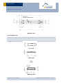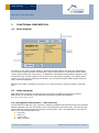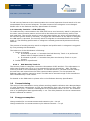
1
USER MANUAL V1.0 Radio Magnet Contact STM 250J / STM 255J December 18, 2013 Observe precautions! Electrostatic sensitive devices! Patent protected: WO98/36395, DE 100 25 561, DE 101 50 128, WO 2004/051591, DE 103 01 678 A1, DE 10309334, WO 04/109236, WO 05/096482, WO 02/095707, US 6,747,573, US 7,019,241 EnOcean GmbH Kolpingring 18a 82041 Oberhaching Germany Phone +49.89.67 34 689-0 Fax +49.89.67 34 689-50 [email protected] www.enocean.com Subject to modifications STM 250J / STM 255J OEM User Manual V1.0 December 18, 2013 1:29 PM Page 1/15 USER MANUAL V1.0 STM 250J / STM 255J OEM REVISION HISTORY The following major modifications and improvements have been made to the first version of this document: No Major Changes V1.0 Initial version Published by EnOcean GmbH, Kolpingring 18a, 82041 Oberhaching, Germany www.enocean.com, [email protected], phone ++49 (89) 6734 6890 © EnOcean GmbH All Rights Reserved Important! This information describes the type of component and shall not be considered as assured characteristics. No responsibility is assumed for possible omissions or inaccuracies. Circuitry and specifications are subject to change without notice. For the latest product specifications, refer to the EnOcean website: http://www.enocean.com. As far as patents or other rights of third parties are concerned, liability is only assumed for modules, not for the described applications, processes and circuits. EnOcean does not assume responsibility for use of modules described and limits its liability to the replacement of modules determined to be defective due to workmanship. Devices or systems containing RF components must meet the essential requirements of the local legal authorities. The modules must not be used in any relation with equipment that supports, directly or indirectly, human health or life or with applications that can result in danger for people, animals or real value. Components of the modules are considered and should be disposed of as hazardous waste. Local government regulations are to be observed. Packing: Please use the recycling operators known to you. © 2013 EnOcean | www.enocean.com STM 250J / STM 255J OEM User Manual V1.0 | Page 2/15 USER MANUAL V1.0 STM 250J / STM 255J OEM TABLE OF CONTENT 1 GENERAL DESCRIPTION ................................................................................. 4 1.1 Basic functionality ......................................................................................... 4 1.2 Technical data ............................................................................................... 4 1.3 Physical dimensions ....................................................................................... 5 1.3.1 Reed contact unit ...................................................................................... 5 1.3.2 Magnet unit .............................................................................................. 6 1.4 Environmental conditions ............................................................................... 7 1.5 Ordering Information ..................................................................................... 7 2 FUNCTIONAL DESCRIPTION ............................................................................ 8 2.1 Block diagram ............................................................................................... 8 2.2 Radio telegram .............................................................................................. 8 2.2.1 Encrypted communication – STM 255J only ................................................... 8 2.2.2 Security Teach-In – STM 255J only .............................................................. 9 2.2.2.1 PSK Security Teach-in ......................................................................... 9 2.3 Transmit timing ............................................................................................. 9 2.4 Energy consumption ...................................................................................... 9 3 APPLICATIONS INFORMATION ....................................................................... 11 3.1 Unit mounting ............................................................................................. 11 3.2 Recommendations for magnet positioning....................................................... 11 3.3 Transmission range ..................................................................................... 13 3.4 Connecting an external backup battery .......................................................... 13 3.5 PSK Labelling .............................................................................................. 14 3.5.1 Included Information: .............................................................................. 14 3.5.2 QR-Code Specification .............................................................................. 14 4 AGENCY CERTIFICATIONS ............................................................................ 15 © 2013 EnOcean | www.enocean.com STM 250J / STM 255J OEM User Manual V1.0 | Page 3/15 USER MANUAL V1.0 STM 250J / STM 255J OEM 1 GENERAL DESCRIPTION 1.1 Basic functionality STM 250J/255J is a wireless magnet contact. The radio sensor is powered by a small solar cell and by that it works absolutely maintenance-free. An integrated energy store allows operation for several days even in total darkness. STM 250J/255J supervises an integrated reed contact and reports every status change immediately (open <> closed). In addition a sign of life signal is transmitted every 20-30 minutes. A LRN button is pre-installed on the PCB. When this button is pressed through a hole in the back plate a special teach-in signal is sent. The reed contact housing and the magnet housing are very small. This means that the EnOcean magnet contact is unobtrusively mountable at every window frame made of aluminum, plastic or wood. STM 250J/255J is designed and qualified for the indoor use in building automation & installation, not for industrial applications (in cause of ESD protection). Typical applications are window, flap and door monitoring. STM 255J provides enhanced security features with encrypted communication 1.2 Technical data Antenna Pre-installed helical antenna installed Frequency EnOcean Equipment Profile1 928.35 MHz EEP D5-00-01 Data rate/Modulation type Conducted Output Power 125 kbps/FSK typ. 0 dBm Power Supply Initial operation time in darkness @ 25°C Operation start up time with empty energy store Reed contact Radio Regulations 1 2 Pre-installed solar cell Illumination 50-100000 lux typ. 6 days, min. 90 hours if energy storage fully charged transmission of telegram every 25 min on average2 typ. 2.5 min @ 400 lux / 25°C incandescent or fluorescent light 1x internal, Meder MK23-90-BV14496 or MK01-I ARIB STD-T108 http://www.enocean-alliance.org/eep Full performance of the PAS614L energy storage is achieved after several days of operation (up to two weeks) at good illumination level. Performance degrades over life time, especially if energy storage is exposed to higher temperatures. Each 10 K drop in temperature doubles the expected life span. © 2013 EnOcean | www.enocean.com STM 250J / STM 255J OEM User Manual V1.0 | Page 4/15 USER MANUAL V1.0 STM 250J / STM 255J OEM 1.3 Physical dimensions 1.3.1 Reed contact unit Dimensions Color of housing 110 x 19 x 15 mm 3 signal white Material of housing PC/ABS Top view Side view Front view 3 Color may change by strong irradiation of sun light! © 2013 EnOcean | www.enocean.com STM 250J / STM 255J OEM User Manual V1.0 | Page 5/15 USER MANUAL V1.0 STM 250J / STM 255J OEM Access to teach-in pushbutton Bottom view 1.3.2 Magnet unit Dimensions 37 x 10 x 5 mm 4 Color of housing signal white Material of housing PC/ABS Top view Side view Front view Bottom view © 2013 EnOcean | www.enocean.com STM 250J / STM 255J OEM User Manual V1.0 | Page 6/15 USER MANUAL V1.0 STM 250J / STM 255J OEM 1.4 Environmental conditions Operating temperature Storage temperature Shelf life (in absolute darkness) Humidity -20 °C … +60 °C, recommended : +10 °C…+30 °C, <60%r.h. 36 months after delivery5 0% … 93% r.h., non-condensing Protection class 1.5 -20 °C … +60 °C 4 IP 40, indoor use only Ordering Information Type STM 250J STM 255J Ordering Code S3061-C250 S3061-C255 Packaging Units 100 pcs 100 pcs 4 Recommended for maximum life of energy storage capacitor Deep discharge of the PAS614L energy storage leads to degradation of performance. Therefore products have to be taken into operation after 36 months. At least the PAS614L needs to be recharged to 2.1V. 5 © 2013 EnOcean | www.enocean.com STM 250J / STM 255J OEM User Manual V1.0 | Page 7/15 USER MANUAL V1.0 STM 250J / STM 255J OEM 2 FUNCTIONAL DESCRIPTION 2.1 Block diagram A change of the reed contact status or pushing the LRN button will wake the transmitter unit to send a radio telegram immediately (reed contact position, LRN push button status, unique 32-bit sensor ID, checksum). In addition a redundant retransmission signal is sent to announce the contact status even in case of no input signal changes. This signal transmitted every 20-30 min, affected at random. The transmit indicator LED flashes briefly at every radio transmission. Between the wake-up phases, the device is in sleep mode for minimum power consumption. 2.2 Radio telegram STM 250J/255J transmits a radio telegram according to EnOcean Equipment Profile EEP D5-00-01 as defined in the EnOcean Equipment Profiles specification. http://www.enocean-alliance.org/eep 2.2.1 Encrypted communication – STM 255J only In STM 255J the data link (DL) content is always protected with advanced security features. Normal operation DL and also teach-in DL are protected in the same way. The security features used are configured by the Security Level format - SLF. This parameter is set by default to the highest possible level: 24-bit RLC, No RLC tx, 4-byte CMAC, VAES encryption © 2013 EnOcean | www.enocean.com STM 250J / STM 255J OEM User Manual V1.0 | Page 8/15 USER MANUAL V1.0 STM 250J / STM 255J OEM To add security features to the communication the normal operation DL and teach-in DL are encapsulated into a secured telegram. The data content of the telegram is not changed. Please refer to the EnOcean Security Specification for details. 2.2.2 Security Teach-In – STM 255J only To enable security communication the STM 255J has to send a security teach-in telegram to the other communication partner and so inform him about the used security profile, keys and initial RLC. The security teach-in has to take place before any other communication can be executed (profile teach-in included). To trigger the transmission of the teach-in telegram the LRN button is pressed. The security teach-in telegram is transmitted before the profile teach-in. The following profile teach-in telegram is already protected by advanced security features. The process of sending security teach-in telegram and profile teach-in telegram is triggered by once pressing the LRN button. The behaviour of the LRN button is following: 1. Button is pressed a. If released in period < 5 seconds then PSK Security Teach-in is performed. Please refer to chapter below for details. b. If released in period > 5 seconds then plain text Security Teach-in is performed. 2. Profile teach-in is performed 2.2.2.1 PSK Security Teach-in The Security Teach-in telegram carries the information of KEY and RLC. This information is either sent as plain text (as is) or it is protected by the pre-shared key - PSK. The PSK must be printed on the transmitting device. To use PSK teach-in, the PSK must be read by the end-user and entered into the other communication partner. For this purpose the EnOcean radio interface cannot be used. The PSK can be entered trough a user interface or semi-automated by a code reader. For details on the PSK teach-in please refer to the EnOcean Security Specification. 2.3 Transmit timing The setup of the transmission timing allows avoiding possible collisions with data packages of other EnOcean transmitters as well as disturbances from the environment. With each transmission cycle, 3 identical subtelegrams are transmitted within 40 ms. The transmission of a subtelegram lasts approximately 1 ms. The delay between the three transmission bursts is affected at random. 2.4 Energy consumption Charge needed for one measurement and transmit cycle: ~80 µC Charge needed for one measurement cycle without transmit: ~10 µC © 2013 EnOcean | www.enocean.com STM 250J / STM 255J OEM User Manual V1.0 | Page 9/15 USER MANUAL V1.0 STM 250J / STM 255J OEM Calculations are performed on the basis of electric charges because of the internal linear voltage regulator of the module. Energy consumption varies with voltage of the energy storage while consumption of electric charge is constant. From these values the following typical performance parameters at room temperature have been calculated: Wake and transmit cycle [s] Operation Time in darkness [h] when storage fully charged Required reload time [h] at 200 lux within 24 h for continuous operation 1500 175 1.8 Assumptions: Internal storage PAS614L-VL3 (after several days of operation at good illumination level) with 0.25 F, Umax=3.2 V, Umin=2.3 V, T=25 °C Consumption: Transmit cycle 80 µC, measurement cycle 10 µC Pre-installed solar cell ECS 300, operating values 3 V and 5 µA @ 200 lux fluorescent light Current proportional to illumination level (not true at very low levels!) These values are calculated, the accuracy is about +/-20%! The performance varies over temperature and may be strongly reduced at extreme temperatures. © 2013 EnOcean | www.enocean.com STM 250J / STM 255J OEM User Manual V1.0 | Page 10/15 USER MANUAL V1.0 STM 250J / STM 255J OEM 3 APPLICATIONS INFORMATION 3.1 Unit mounting Both the reed contact unit as well as the magnet contact unit is very thin and flat. This means that they are unobtrusively mountable at every window or doorframe made of aluminum, plastic or wood. Mounting position of the reed contact is horizontal, vertically or even tilted. The arrow signs on the base of the reed contact should be directed downward. In this mounting position, the STM 250J/255J housing offers protection against splashing water drops. Mounting STM 250J/255J on metal surfaces or aluminum window frames will reduce the transmission range. Therefore please note that a radio receiver unit should not be mounted in the same plane as the STM 250J/255J base plate, because in extension of the metal surface the transmission range is reduced by physical radio transmission effects of the antenna near to metal. For example the receiver should not be mounted at the window front side. 3.2 Recommendations for magnet positioning The flat magnet should be positioned by facing the housing in the middle of the reed contact marking as follows: Reed contact marking Righted positioning of the magnet (Typical for window mounting) The magnet can be positioned in vertical or in horizontal position to the reed contact housing. The distance between housing and magnet should be less than 5 mm. Reed contact marking Planar positioning of the magnet (Typical for door mounting) © 2013 EnOcean | www.enocean.com STM 250J / STM 255J OEM User Manual V1.0 | Page 11/15 USER MANUAL V1.0 STM 250J / STM 255J OEM The round-pole magnet can be removed from the magnet housing. This enables smart embedding into wooden window casements in square position to the reed contact housing. But note that the round-pole must be mounted beside the reed contact marking, as follows: or: Pole-faced positioning of magnet (Typical for mounting at wooden window casements) The distance between housing and magnet should be less than 4 mm when using this mounting position. Always take care for sufficient distance of the magnet to magnetic data carriers, e.g. credit cards. Data could be erased! © 2013 EnOcean | www.enocean.com STM 250J / STM 255J OEM User Manual V1.0 | Page 12/15 USER MANUAL V1.0 STM 250J / STM 255J OEM 3.3 Transmission range The main factors that influence the system transmission range are type and location of the antennas of the receiver and the transmitter, type of terrain and degree of obstruction of the link path, sources of interference affecting the receiver, and “dead” spots caused by signal reflections from nearby conductive objects. Since the expected transmission range strongly depends on this system conditions, range tests should categorically be performed before notification of a particular range that will be attainable by a certain application. The following figures for expected transmission range are considered by using a PTM, a STM or a TCM radio transmitter device and the TCM radio receiver device with preinstalled whip antenna and may be used as a rough guide only: Line-of-sight connections: Typically 30 m range in corridors, up to 100 m in halls Plasterboard walls / dry wood: Typically 30 m range, through max. 5 walls Ferroconcrete walls / ceilings: Typically 10 m range, through max. 1 ceiling Fire-safety walls, elevator shafts, staircases and supply areas should be considered as screening. The angle at which the transmitted signal hits the wall is very important. The effective wall thickness – and with it the signal attenuation – varies according to this angle. Signals should be transmitted as directly as possible through the wall. Wall niches should be avoided. Other factors restricting transmission range: Switch mounted on metal surfaces (up to 30% loss of transmission range) Hollow lightweight walls filled with insulating wool on metal foil False ceilings with panels of metal or carbon fiber Lead glass or glass with metal coating, steel furniture The distance between EnOcean receivers and other transmitting devices such as computers, audio and video equipment that also emit high-frequency signals should be at least 0.5 m. A summarized application note to determine the transmission range within buildings is available as download from www.enocean.com. 3.4 Connecting an external backup battery In case there is not sufficient light available for operation with solar cell an external 3 V Lithium backup battery can be connected to the PCB inside the module at the soldering pads shown below: © 2013 EnOcean | www.enocean.com STM 250J / STM 255J OEM User Manual V1.0 | Page 13/15 USER MANUAL V1.0 STM 250J / STM 255J OEM 3.5 PSK Labelling For the PSK information a specific QR code is placed on the module itself. Information of the QR code: 3.5.1 Included Information: [ID:XXXXXXXX PK:YYYYYYYYYYYYYYYYYYYYYYYYYYYYYYYY] ID: XX FREESPACE PK: YY 3 CHARS 8 CHARS 1 CHARS 3 CHARS 32 CHARS = 47 CHARS 3.5.2 QR-Code Specification QR-Code version: Error correction level: Mode: Character capacity: 3 (29x29 pixel) Q (25% error correction) Alphanumeric Mode 47 Keep off area around the code: Pixel size: 2 pixel (up, down, left and right) min. 4x4 points per pixel 600dpi x 600dpi Resolution: 1 print point: 0.0423mm x 0.0423mm 1 pixel: 0.1693mm x 0.1693mm © 2013 EnOcean | www.enocean.com STM 250J / STM 255J OEM User Manual V1.0 | Page 14/15 USER MANUAL V1.0 STM 250J / STM 255J OEM 4 AGENCY CERTIFICATIONS The radio modules inside STM 250J (module: STM 429J) and STM 255J (module: STM 425J) have been designed and tested to fulfil the approval requirements for ARIB STD-T108 based on the built-in firmware. They carry the following marking: The OEM must refer to this marking in related product documentation! These products are offered solely as finished products for OEM customers and without an EnOcean label. The OEM partners as the instance responsible for marketing them must add certifications and product identification. EnOcean assumes no responsibility of any kind for OEM products to end-users. © 2013 EnOcean | www.enocean.com STM 250J / STM 255J OEM User Manual V1.0 | Page 15/15