1
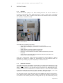
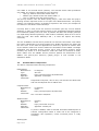
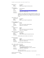
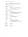
i-Bridge 2 / Time Box 4 Ad Hoc Data Communication SUM-AHR-01 System User Manual Ad Hoc Router (AHR) Version Date Status Service Release 1.2 December, 8th 2010 Final SUM-AHR-01 | System User Manual - Ad Hoc Router | December 8th, 2010 Colofon Directie Wapensystemen Command and Control Support Centre Postal address DMO/ST/DWS/C4I/C2SC MPC 53B Postbus 3003 3800DA AMERSFOORT Visitors address Bernhardkazerne Building AC 11 Barchman Wuytierslaan 198 3818 LN AMERSFOORT Contact Ing C.C. Boot. ICT Architect T +31 (0)33 421 56 08 MDTN *06 500 15608 M +31(0)6 2432 1080 [email protected] Version Contracting authority Project number SR1.2 EN Project manager i-Bridge Page 3 of 39 SUM-AHR-01 | System User Manual - Ad Hoc Router | December 8th, 2010 Contents Colofon........................................................................................................ 3 1 Introduction .......................................................................................... 6 1.1 Ad hoc data communication ................................................................. 6 1.2 Ad hoc network in i-Bridge Timebox-3 ................................................... 6 1.3 Ad Hoc Router .................................................................................... 7 1.4 Structure ........................................................................................... 8 2 Ad Hoc Router........................................................................................ 9 2.1 General ............................................................................................. 9 2.2 Network functions ............................................................................... 9 2.3 Used hardware components ............................................................... 10 2.4 Used software components................................................................. 13 2.5 Scripts ............................................................................................ 14 2.6 Daemon programs ............................................................................ 15 2.7 Configuration files ............................................................................. 15 2.8 Installation and configuration ............................................................. 15 2.9 Reinstallation and upgrade ................................................................. 16 2.10 Change management....................................................................... 17 3 Ad Hoc Network Dashboard ................................................................. 18 3.1 General ........................................................................................... 18 3.2 Installation ...................................................................................... 18 3.3 Use: general .................................................................................... 20 3.4 Status bar........................................................................................ 21 3.5 Navigation bar and transition to expert mode ....................................... 24 3.6 Network view ................................................................................... 25 3.7 GPS view ......................................................................................... 26 3.8 Browser view ................................................................................... 27 3.9 Expert view...................................................................................... 29 3.10 Gateway view ................................................................................. 30 3.11 Logging ......................................................................................... 31 3.12 Configuration.................................................................................. 32 3.13 Scripts........................................................................................... 32 4 Satellite terminals ............................................................................... 33 4.1 General ........................................................................................... 33 4.2 Iridium OpenPort .............................................................................. 33 4.3 Inmarsat BGAN / Thrane Explorer 700 ................................................. 35 5 WRT610N WiFi Access Point en Ethernet Switch.................................. 38 5.1 General ........................................................................................... 38 5.2 Installation and configuration ............................................................. 38 Page 5 van 39 SUM-AHR | System User Manual - Ad Hoc Router | December 8th, 2010 1 Introduction 1.1 Ad hoc data communication Coordination of services for crisis management and disaster recovery requires that the availability of communication between units in the field and between field and control room and crisis centre is sufficiently guaranteed. Data communication between control room / crisis centre and field units is provided using public cellular systems (GPRS / UMTS / HSPA+). Due to the lack of nationwide coverage and due to failure or overload satellite communication is being used. Communication between units in the field is provided through wireless connections between them. The mode being used is the “ad hoc mode”, which provides high availability because there is no dependence on base stations or other coordinating elements. Each vehicle can directly communicate with other vehicles provided in range of the radio. ad hoc network: A wireless ad hoc network is a decentralized wireless network. The network is ad hoc because it does not rely on a pre-existing infrastructure, such as routers in wired networks or access points in managed (infrastructure) wireless networks. Instead, each node participates in routing by forwarding data for other nodes, and so the determination of which nodes forward data is made dynamically based on the network connectivity. (source: en.wikipedia.org) The range of the WLAN connections is improved by using a MANET routing protocol. MANET ensures communication between stations; each vehicle operates as a relay station. 1.2 Ad hoc network in i-Bridge Timebox-3 The ad hoc network designed for i-Bridge 2 is a combination of direct mutual communication (local, MANET), and exchange of information with the fixed infrastructure (global, internet). This concept supports so-called peer-to-peer applications, where messaging occurs between the workstations connected to the MANET, and to workstations outside the MANET through the fixed infrastructure. Of course, applications have to support this peer-to-peer concept. The Eagle One system uses Microsoft Groove as a middleware product. This works very well in the ad hoc network. Figure 1: Combination of local ad hoc (blue) and global networks (orange) Page 6 of 39 SUM-AHR-01 | System User Manual - Ad Hoc Router | December 8th, 2010 The figure below shows how global and ad hoc networks cooperate to provide the connections for consumers as well as possible. In the field GPRS / UMTS coverage is very limited. Using satellite terminals clusters of vehicles (the MANETs) are unlocked - in this figure there are three MANETs. Figure 2: Ad hoc network in the case of fire fighting Servers in the fixed infrastructure ensure data exchange between the individual MANETs and control room / crisis centre. For this purpose a "store and forward mailbox system, also called " Disruptive Tolerant Networking (DTN), is being used. All messages to workstations outside the MANET are placed on a (MS-Groove, Movida) relay server, so other stations can retrieve data from this server. Hence it is possible to exchange messages, regardless of direct communication paths. This functionality is essential because in case of dynamic IPv4 addresses and / or Network Address / Port Translation (NAPT) direct connections are not easy to establish. Also the degree of availability of direct connections is lower. 1.3 Ad Hoc Router Each vehicle in need of access to the ad hoc network is equipped with an Ad Hoc Router (AHR). The AHR is equipped with a WLAN and UMTS radio module and a GPS receiver. For good performance antennas are mounted on the roof of vehicles. The type of the WLAN antenna is "high gain", which provides a good range. Page 7 van 39 SUM-AHR | System User Manual - Ad Hoc Router | December 8th, 2010 Figure 3: Concept Ad hoc netwerk 1.4 Structure This document is used by the system administrators of the ad hoc network. It describes the management task for the following components: • Ad Hoc Router Chapter 2 • Ad Hoc Network Dashboard Chapter 3 • Satellite terminals Chapter 4 There is no documentation for end users, because the system requires no operation interventions. However, users must take note of the system, e.g. by instructions from an experienced user or system administrator. System management is responsible for this task. The Ad Hoc Router and Ad Hoc Network Dashboard are products developed by the C2SC. Currently existing and already available components are used as much as possible. Documentation of these components is added as appendices or can be viewed via web sites as indicated in the relevant sections. Page 8 of 39 SUM-AHR-01 | System User Manual - Ad Hoc Router | December 8th, 2010 2 Ad Hoc Router 2.1 General The Ad Hoc Router (AHR) is the basic building block of the ad hoc network. It provides communication with WLAN and GPRS / UMTS / HSPA+ and is equipped with a GPS receiver. Also, a remote access device to the Internet can be connected, for example, a satellite terminal. Figure 4: Ad Hoc Router The AHR has the following interfaces: • LAN: Ethernet LAN port, vehicle network, Linux eth0 • WAN: Ethernet WAN port, connection of external internet facility Linux eth1 • WLAN: antenna connector WLAN roof antenna • UMTS main: antenna connector roof antenna • UMTS aux: second antenna connector UMTS roof antenna, for better reception • GPS: antenna connector GPS roof antenna connector, with 5V DC for antenna with internal amplifier There is no on/off switch. Under normal circumstances, the AHR always is always powered on. Restart is possible by disconnecting the LAN Ethernet cable or otherwise by disabling the power temporarily in another manner. 2.2 Network functions The AHR provides the workstations connected to the vehicle LAN connectivity to the Internet and connectivity between them. Internet connectivity is provided through GPRS / UMTS / HSPA+ or an external device connected to the WAN Ethernet port. Mutual connections are established via a WLAN network, in which the OLSR MANET protocol automatically maintains a network topology. Within the MANET, each node operates as a relay station, increasing the reach of WLAN significantly. An AHR with Internet access provides the entire MANET with Internet connectivity, hence stations lacking GPRS / UMTS / HSPA+ coverage still maintain connectivity to the Internet. The network protocols are configured in a way that UMTS takes priority Page 9 van 39 SUM-AHR | System User Manual - Ad Hoc Router | December 8th, 2010 over GPRS or an external device (satcom). The external device takes precedence over GPRS. The system is designed for three priorities: • High (H): default routes with subnet mask / 2 • Medium (M): default routes with subnet mask / 1 • Low (L): default route with subnet mask / 0 This priority scheme uses the OLSR dynwg plug-in, C2SC has made this plug-in working and the improved version is now part of the OLSR distribution. The priority scheme is a temporary facility. It should be replaced in the end by for example the new feature in the OLSR: Smart Gateways. Currently IPv4 is used; hence the Internet connection gets only one IP address assigned. In order to provide Internet access to the workstations Network Address Port Translation (NAPT) has to be used. A problem with NAT and multiple gateways is a rapid change between gateways, which leads to instability. OLSR is set to not to swap too fast. Also Smart Gateways and / or IPv6 will replace this facility eventually. The use of MANETs’ internal links is preferred over Internet connections. This makes the system independent of a fixed infrastructure, WLAN connections are faster and the use is free. To be useful for applications a "discovery” protocol is needed. After all, the stations must know if other stations are accessible via the MANET. The Eagle application uses Microsoft Groove. Groove has a node presence protocol, which normally only works on a wired Ethernet. C2SC has made an extension to OLSR, which makes sure the MANET Groove presence packets are distributed in the MANET. The peer-to-peer discovery (p2pd) plug-in is now included in the distribution OLSR. 2.3 Used hardware components The AHR is composed of the following components: Motherboard: Manufacturer: PC Engines Type: Alix 6e2 Website: http://www.pcengines.ch/alix6e2.htm Appendix: Appendix 2.1 Alix.pdf Comments: Single board computer, with CF slot, mini-PCI slot for WLAN card and mini-PCI Express slot for UMTS card. Compact Flash: Manufacturer: PC Engines Type: cf4slc Website: http://www.pcengines.ch/cf4slc.htm Comments: SLC: 100.000x read/write WLAN module: Manufacturer: Ubiquity Type: XR2 Website: http://www.ubnt.com/xr2 Appendix: Appendix 2.2 XR2.pdf Comments: Tx power is 28dBm, which is 600mW. Permitted radiated power is 100mW. Configuration offset is 10dB. Has to be configured in accordance with legislation, unless increased power is really necessary. WLAN pigtail: Page 10 of 39 SUM-AHR-01 | System User Manual - Ad Hoc Router | December 8th, 2010 Manufacturer: Type: Website: PC Engines mmcxnf http://www.pcengines.ch/mmcxnf.htm UMTS module: Manufacturer: Type: Website: Appendix: Comments: Sierra Wireless MC8700 http://www.sierrawireless.com/productsandservices/… AirPrime/Embedded_Modules/MC_Series/MC8700.aspx Appendix 2.3 MC8700.pdf Firmware of the UMTS card has been upgraded to version 3.0.9. Upgrade tool and images are available, but not delivered with SR1, because of the size of the images (new and old version: 20MB). UMTS pigtails (2x): Manufacturer: Type: Website: PC Engines pignf6 http://www.pcengines.ch/pignf6.htm Ethernet adapters (2x): Manufacturer: Diswire Type: VRJ-45 Website: http://www.gandalf.nl/pdf/vrj45.pdf Appendix: Appendix 2.4 VRJ45.pdf Casing: Manufacturer: Type: Website: Appendix: Diswire ADOE http://www.diswire.com/SpecsADOE.pdf Appendix 2.5 ADOE.pdf Motherboard mounting in enclosure: Manufacturer: PC Engines Type: case1c1blku Website: http://www.pcengines.ch/case1c1blku.htm Comments: Bottom plate glued in ADOE. Front removed. DC Power Injector: Manufacturer: Diswire Type: POEsie Website: http://www.diswire.com/SpecsPOEsie.pdf Appendix: Appendix 2.6 POEsie.pdf Comments: Power throughput via Ethernet0 poort. GPS / GPRS / UMTS roof antenna: Manufacturer: Hirschman Type: GPS 916 V Flex Website: http://products.hirschmann-car.com/ SepiaPIMWeb/files/GPS_916_918_V_FLEX.pdf Appendix: Appendix 2.7 GPS916.pdf Comments: GPS active antenna, 5V GSM/GPRS/UMTS antenna, 880-960 en 1700-2100 MHz WLAN roof antenna vehicle Manufacturer: Comet Page 11 van 39 SUM-AHR | System User Manual - Ad Hoc Router | December 8th, 2010 Type: Website: Appendix: Comments: SF-245SPR, MG-4N http://www.cometantenna.com/newPro_detail.php?ID=220 Appendix 2.8a sf-245sp.pdf, Appendix 2.8b MG-4N.pdf Spring in antenna mount WLAN roof antenna: Manufacturer: Type: Website: Appendix: Comments: canopii ca240711 http://www.wlan-shop.nl/site/downloadpdf.php? file=wlanshop_canopii_ca240711_datasheet.pdf Appendix 2.9 ca240711.pdf Alternative if Comet SF-245SPR is not usable GPRS / UMTS mast antenna: Manufacturer: Procom Type: CXL 900/1800/UMTS LW Website: http://cms2pdf.com/procom.php?id=7369&name= GCXL9001800UMTSLW&language=eng&style=low Appendix: Appendix 2.10 CXL9001800UMTSLW.pdf WLAN mast antenna: Manufacturer: Type: Website: Appendix: GPS receiver: Manufacturer: Type: Website: Appendix: Stella Doradus 24-1360 http://www.stelladoradus.com/pdfs/2.4omni/ 24.1360.(01-09-09).pdf Appendix 2.11 24.1360.pdf U-Blox EVK-5H-0 http://www.u-blox.com/en/download/ documents-a-resources.html http://www.u-blox.com/images/downloads/Product_Docs /GPS_Compendium%28GPS-X-02007%29.pdf Appendix 2.12 EVK-5.pdf GPS pigtail: Manufacturer: Type: Active-robots SMA-L225 GPS USB cable: Manufacturer: Type: USB Firewire RR-ABR01-12G Page 12 of 39 SUM-AHR-01 | System User Manual - Ad Hoc Router | December 8th, 2010 Figure 5: Ad Hoc Router, internal 2.4 Used software components In service release 1 (SR1) the following Open Source software modules are used: Operating system: Name: Voyage Linux Version: 0.6.5 Web site: http://linux.voyage.hk/ Extended with the following Debian packages: bzip2_1.0.5-1_i386.deb ifplugd_0.28-12_i386.deb libdaemon0_0.12-2lenny1_i386.deb libfam0_2.7.0-13.3+lenny1_i386.deb libgcrypt11_1.4.1-1_i386.deb libgdbm3_1.8.3-3_i386.deb libgnutls26_2.4.2-6+lenny2_i386.deb libgpg-error0_1.4-2_i386.deb libldap-2.4-2_2.4.11-1+lenny1_i386.deb libpcre3_7.6-2.1_i386.deb libsasl2-2_2.1.22.dfsg1-23+lenny1_i386.deb libtasn1-3_1.4-1_i386.deb libterm-readkey-perl_2.30-4_i386.deb libterm-readline-perl-perl_1.0302-1_all.deb libuniconf4.4_4.4.1-1.1_i386.deb libwvstreams4.4-base_4.4.1-1.1_i386.deb libwvstreams4.4-extras_4.4.1-1.1_i386.deb libxplc0.3.13_0.3.13-1_i386.deb lighttpd_1.4.19-5+lenny1_i386.deb mime-support_3.44-1_all.deb minicom_2.3-1_i386.deb netcat-traditional_1.10-38_i386.deb perl-modules_5.10.0-19lenny2_all.deb perl_5.10.0-19lenny2_i386.deb psmisc_22.6-1_i386.deb MANET protocol: Name: Version: Web site: OLSR 0.6.0 pre-release March 12th, 2010 http://www.olsr.org/ Page 13 van 39 SUM-AHR | System User Manual - Ad Hoc Router | December 8th, 2010 WLAN driver: Name: MadWifi Version: 0.9.4 (r4119) with patches Web site: http://madwifi-project.org/ Peculiarities: Patches are applied for ad hoc mode in combination with QoS (WME) (Ronald van Wee) and bridging (Ronald in’t Velt). The patch of Ronald in ’t Velt permits the WLAN interface to be used for MANET protocols. In the so-called AHDEMO mode the WLAN network is not announced with beacons, though the BSSID MAC address is used for the ad hoc network. This renders the network invisible for normal users (stealth mode). Sierra driver: Name: Version: Web site: Sierra.ko 1.7.34 http://sierrawireless.custhelp.com/app/answers/detail/a_id/ 500/~/can-i-use-my-sierra-wireless-modem-on-a-linuxoperating-system-%3F-(-v.1.7.32) Peculiarities: Version 1.7.34 is a pre-release, obtained after problem ticket with title: MC8700 - 1.7.32 - force halt / intr urb failed [Incident: 100714-000007]. 2.5 Scripts In folder /usr/local/sbin a number of scripts for management tasks are made available: ahr-init ahr-log grub-cf1 install-delta install-on-usb install-tar olsr post-reinstall reboot-cf1 ro-cf1 ro-cf2 rw-cf1 rw-cf2 sync-tmp-fs umts update-nodenum update-routes v1 v2 Start and stop daemons with script in /etc/init.d Simple access to a view on /var/log/syslog Update grub bootmanager binaries (after update menu.lst) Put configuration files in delta-folders in cf1 en cf2 Cloning of the distribution on CF via USB port Extract delta files in delta folders Show OLSR status, start and stop of OLSR Installing and configuring after reinstallation Reboot, from partition cf1 Render partition cf1 read only Render partition cf2 read only Render partition cf1 read-write Render partition cf2 read-write Secure temporary files on flash (under cron) Show UMTS status (requires stopping umtsinfod daemon) Set (install-delta) or update node Script, used by umtsinfod for Internet priority Use vi editor on read-only, partition cf1 Use vi editor on read-only, partition cf2 Scripts on the cf1 maintenance partition: update-nodenum clone-cf2-to-usb post-reinstall reboot-cf2 reinstall-cf2 ro-cf1 ro-cf2 Page 14 of 39 Set (install-delta) or update node Cloning of partition cf2 via USB Installing and configuring after reinstallation Reboot, from partition cf2 Install and put base configuration on partition cf2 Render partition cf1 read only Render partition cf2 read only SUM-AHR-01 | System User Manual - Ad Hoc Router | December 8th, 2010 rw-cf1 rw-cf2 2.6 Render partition cf1 read-write Render partition cf2 read-write Daemon programs The C2SC has made software to monitor the Internet connection, and for picking up and passing on the status of the AHR to the Ad Hoc Network dashboard. Supplied data are the status of the UMTS, the status of the MANET connections (OLSR), the WAN port (satcom) and the information of the GPS receiver. The information is sent through NMEA messages, over an IP/UDP multicast channel. Each workstation on the Vehicle LAN can subscribe itself on this information channel, so that several workstations can exploit this information. The format of the messages has been described in appendix 2.A. Daemons: ahrnetd ahrwd ahrgpsd ahrwand ahrwland To collect and pass on network status Watchdog function daemons To collect and pass on network status GPS data, synchronize system time To collect and pass on UMTS en WLAN status, set priority internet connection To collect and pass on status WLAN interface Description of configuration files in appendix 2.B 2.7 Configuration files The configuration files, which deviate from the default settings in the Voyage Linux distribution, are put in the delta-cf1 and delta-cf2 folders on partition cf1. These partitions are mounted on /mnt/cf1. In the configuration files a variable QnodenumQ is used. During the installation and application of the configuration the variable is adjusted to the correct value. 2.8 Installation and configuration Before the AHR is assembled a Compact Flash card (CF) has to be setup, i.e. the Linux operating system is put into place. Also the AHR is configured with IP addresses that belong to the vehicle. Appendix 2.C contains a list with vehicles to which an AHR has been assigned. It contains the vehicle numbers and the granted IP addresses. The IP addresses have been chosen according to a presented diagram in appendix 2.D. If the ad hoc network is deployed nationwide, this IP address assignment diagram must be coordinated and ratified. Access to the AHR command prompt is secured using the protected ssh protocol. The system managers know all passwords. Passwords on the AHR and the Ad Hoc Network Dashboard are equal. At this moment there is no update procedure. The setup of the CF card happens with the install-on-usb script, and can be carried out from each AHR. Thus the installation can be cloned. install-on-usb node-number { nbs } Page 15 van 39 SUM-AHR | System User Manual - Ad Hoc Router | December 8th, 2010 Parameter node-number determines the name of the router, and is a double-digit number. The installation creates two partitions, with labels cf1 en cf2. Partition cf1 is a complete Linux installation for management purposes and can be used for the reinstallation of partition cf2. Partition cf2 is used in normal operation. Both partitions are read-only during normal operation. Partition cf1 contains the source files for the installation of partition cf2. The configuration files for partition cf1 are also present. voyage-0.6.5.tar.bz2 delta-deb.tar delta.tar by C2SC delta-nbs.tar Linux installation file Additional Debian programs Configuration files and additional programs, maintenance Additional configuration, for test environment C2SC The node number can be adjusted, for example when you want to change a AHR in a vehicle; IP addresses are allocated to a vehicle, not to a AHR. Adjustments are done wit the following script: update-nodenum { node-number } Parameter node-number is a two-digit number. Without a parameter the script parses the number from the hostname; this is olsr-rt[node-number] for the C2SC test environment or hgm-57-[node-number] for the HGM AHRs. Configuration of an AHR in operation is performed using the Ad Hoc Network Dashboard, described in chapter 3. Examples are WLAN Tx Power and preference settings for UMTS and the Ethernet WAN port. Other configuration modifications are not necessary under normal circumstances. Hence, no tools have been developed to support this process. If configuration changes are necessary, the configuration files can be changed. This is possible with an editor, such as vi. Basic knowledge of Linux is necessary to bring this to a good end. 2.9 Reinstallation and upgrade Reinstalling or upgrading the system is relatively simple. For this the maintenance partition cf1 is used. Reinstallation of partition cf2 is done using the following files (in the root of partition cf1): voyage-0.6.5.tar.bz2 Base file Voyage Linux delta.tar Modifications to the basis Voyage Linux delta-deb.tar Software modules that are added (debian packages) The “delta tar files” are extracted in the next two folders, also on partition cf1: delta-cf1 Modifications to the basis Voyage Linux, partition cf1 delta-cf2 Modifications to the basis Voyage Linux, partition cf2 The files in this folders are “parameterized”, for example with parameter QnodenumQ. If the delta files are applied the parameters have to be changed with the correct values for that node. The procedure for reinstallation: 1. reboot-cf1 Reboot system from the maintenance partition 2. -Wait the end of the restart process, log in 3. reinstall-cf2 Reinstall partition cf2 4. reboot The system will start now the new installed version Page 16 of 39 SUM-AHR-01 | System User Manual - Ad Hoc Router | December 8th, 2010 5. -Wait for restart, log in 6. post-reinstall Install additional packages and updates 7. reboot Activate additional packages/modifications 8. -Wait for restart, log in, validate the new installation During the reinstallation the name of the system and the derived parameters remain unchanged as before the reinstallation. Modifications can be applied with updatenodenum. Upgrading the system follows a similar process as the reinstallation. Before the installation new installation files are extracted. Follow this procedure: 1. rw-cf1 Put partition cf1 in read-write mode 2. cd /mnt/cf1 Make root of partition cf1 current 3. scp –p [ip address]://[file name] ./ Put files from another system onto this system. E.g.: scp –p 172.31.63.39://delta.tar ./ 4. install-tar Put delta file in delta folders 5. install-delta Put files in delta folders on the current system. Dependent on the update it could be necessary to perform a reboot or a reinstallation. The firmware of the Sierra Wireless UMTS module can be changed. This is the procedure: 1. it ahrwand stop Stop WAN monitor deamon 2. killall pppd Stop possible pppd sessies 3. rw-cf2 Put partition cf2 in read-write mode 4. cd / Make root home folder (/root) current 5. scp –p [ip-adres]://sierra.tar ./ Put firmware of another system onto this system. 6. 7. 8. 9. 10. tar xf sierra.tar cd sierra ./upgrade.sh reboot -- 2.10 Extract installation files Make sierra folder current Perform firmware upgrade Acivate additional packages/modifications Wait for restart, log in, validate new installation Change management The change log of the AHR configuration is stored in file /mnt/cf1/deltacf2/changelog-hgm.txt Page 17 van 39 SUM-AHR | System User Manual - Ad Hoc Router | December 8th, 2010 3 Ad Hoc Network Dashboard 3.1 General The Ad Hoc Network Dashboard (AHND) is an application, which ensures a view on the status of ad hoc network. All shown information is collected and is supplied by the set of daemons on the AHR, see chapter 2.6. IP multicast is used for the distribution of the daemon messages on the vehicle LAN, which does not impose restrictions on the number of connected workstations and dashboard software. A PC or lap top connected to the vehicle LAN can be used as to form a picture of the ad hoc network by means of status messages and the AHND. Moreover a user can use the AHND to configure a number of items on the ad hoc the router. This paragraph describes the AHND. The installation will be described firstly, afterwards the different views and the interaction of the user with the AHND. 3.2 Installation Requirements for the AHND software: Windows XP SP2 or higher .NET Framework 3.5 SP1 download link: http://www.microsoft.com/downloads/details.aspx?familyid=ab99342f5d1a-413d-8319-81da479ab0d7&displaylang=en The AHND is delivered as a msi file. You can find this file on each AHR and you can download this file from the AHR using a standard browser. The URL: http://10.a.b.1:8080/AHND.msi On eagle laptops you have to be logged in as an administrator. The characters a and b should be replaced to obtain the correct IP address. Each AHR wears a label “AHR-a-b”. Or you can obtain the IP address of the router: 10.a.b.nn. Page 18 of 39 SUM-AHR-01 | System User Manual - Ad Hoc Router | December 8th, 2010 If you open the URL, the downloading will start. Click “Install” if you wish to install the AHND software. The installation process is simple (read: a few clicks on the Next button). If you should decide to change the path of the installation folder of the software, you should also execute a change in the Windows registry. If you do not, the automatic starting of the software after login will not work anymore. So, if you change the path/folder here: you also have to change the value of the AHND key manually (complete path of the key=HKLM/Software/Microsoft/Windows/CurrentVersion/Run/AHND): Page 19 van 39 SUM-AHR | System User Manual - Ad Hoc Router | December 8th, 2010 3.3 Use: general The AHND user interface consists of 3 regions: - On top the status bar, summary report of the status of the AHR and the network; On the left a navigation bar, allowing you to select different detail views; Detail view with status of the network, GPS and other information. An example of a screenshot, showing you how the AHND can look (active view is the network view): Page 20 of 39 SUM-AHR-01 | System User Manual - Ad Hoc Router | December 8th, 2010 In the next sections each part of the UI is discussed. 3.4 Status bar The status bar consists of a few zones. The connection to the Internet is being rendered in orange: the priority (L, M, H), via WAN, UMTS or another node in the MANET. The figure above shows that the Internet connection goes via UMTS, priority High. Summary of the status of the router - - - The AHR LED indicates if the application is receiving messages from the AHR. If this is the case, the LED is green. Otherwise it’s red. This means the same thing as “no AHR present”. The GPS LED indicates if a GPS device is connected and if a valid position fix is available: green: everything is ok orange: the AHND receives GPS messages, but there is no GPS fix red: no GPS messages are being received (no GPS device present) The Power LED indicates if the laptop, on which the AHND is running, is running on AC or on a battery: green, laptop is running on AC power, red: power is running on a battery. Status Internet connectivity Page 21 van 39 SUM-AHR | System User Manual - Ad Hoc Router | December 8th, 2010 The status of the Internet connection is visualised by a “priority control. This priority control shows which priority routes the router has in its route table: - L: low: prio 0: Internet route with /0 net mask - M: medium: prio 1: Internet routes with /1 net mask - H: high: prio 2: Internet routes with /2 net mask Internet routes with an H label have priority on routes with a M label, which have in turn priority over routes with a L label. Details about the routes are shown if you put your mouse pointer on the “priority control” (in a tooltip) or in the network view, where nodes fulfilling the role gateway, get an orange fill colour The routes with priority are standard default gateways: 0.0.0.0/0. To obtain access to the Internet this route is created by the external device, for example UMTS (with the protocol) or the WAN port (with DHCP). The other routes with higher priority are created by the ahrwand daemon on the AHR, as upgrade of the standard default gateway. WAN status (status of the eth1 interface) In the control showing the WAN status: - Left bottom: the address of the gateway connected to the eth1 interface, e.g. a SATCOM device or a fix Ethernet connection. - Right top: Rx and Tx, the amount of traffic that has been sent and received over the eth1 interface. WARNING!: these are not the real traffic statistics of for example a SATCOM terminal. If the router is rebooted, these counters are reset. - Right bottom: the status message: OK, NO ADDRESS, … - The orange background indicates if an interface is used as gateway. If the background is black, then eth1 (WAN) is not used as a gateway to the Internet. If the control is not present in the status bar, then the WAN interface (eth1) is not active. UMTS status (status of the ppp0 interface) The control describing the UMTS status is similar to that of the WAN status: - Left bottom: the signal strength, a value between 0 and 31 (included). A higher value means a better “reception”. - Middle top: the mobile provider, in this case “vodafone NL”. - To the right: the RAT (Radio Access Technology): possible values are GPRS, UMTS, HSDPA, HSDPA/HSUPA en HSPA+ - Right top: Rx and Tx counters. Meaning: see description Rx/Tx of WAN status. - Right bottom: the status message: OK, NO SERVICE, … Page 22 of 39 SUM-AHR-01 | System User Manual - Ad Hoc Router | December 8th, 2010 - The background of the UMTS control gets an orange fill colour, if ppp0 is a gateway and it gets a red colour in case of an error situation. WLAN status (status of the ath0 interface) The description of the WLAN (ath0 interface) status control: - Left (right to the WLAN label): a Tx power selection control. In the configuration file of the AHND are two parameters defined: low Tx power and high Tx power (in dBm). The default values are 10dBm and 17dBm. If the preconfigured Tx power of ath0 is not one of these values, you will get a notification (“Tx Power is 4 dBm. Click to repair!”). If you click this button, the value of Tx low power will be set, as defined in the configuration file of the router. From then on, clicking the button, switches the Tx power parameter between Tx low and Tx high. - Middle: channel. The number below “channel” shows the used WLAN channel. In this example it is 40: 802.11a, freq. 5.2 GHz. By default the AHR uses channel 11, i.e. 2642Mhz. - Right top: Rx and Tx counters. Meaning: see description Rx/Tx of WAN status. - Right bottom: the status message: OK, NO ADDRESS, … Page 23 van 39 SUM-AHR | System User Manual - Ad Hoc Router | December 8th, 2010 3.5 Navigation bar and transition to expert mode The vehicle number is shown on top of the navigation bar. Upper screenshots show that the navigation bar has two modes: - User mode, with choices network view and GPS view - Expert mode: with extra views: browser, expert and gateway. To get this extra functionality, you just have to push the “lock” button. After this action a login view will appear, in which you can enter a PIN. If the PIN is correct, you will get access to the extra views. Page 24 of 39 SUM-AHR-01 | System User Manual - Ad Hoc Router | December 8th, 2010 3.6 Network view The network view has different regions: Network topology region The AHR itself is placed in the centre of the figure. Around that centre the direct neighbours are shown. Some neighbours are relays to nodes a couple of more hops away in the network. The number of such nodes (or IP subnets) is shown in a black, smaller circle. Each fill colour of the nodes has a meaning: -‐ Orange: node direction Internet connection (in this case it is the node itself) -‐ Blue: another node -‐ Gray: unknown node, vehicle number unknown (IP address is shown instead, first and last byte dropped). In the situation of the figure above, 0304 and 0307 are relays, 0304 to 12 nodes and 0207 to 11 nodes. If you move the mouse over a black circle, a tooltip appears showing you details about the nodes ‘behind’ the relay: Page 25 van 39 SUM-AHR | System User Manual - Ad Hoc Router | December 8th, 2010 In this list you notice that 0304 is a relay for 1220 (name column) for which 3 hops (hops column) are needed to reach it. There is also a direct link with node 1220, but of such bad quality that it is not usable (red dotted line in the network diagram). In the 2 other columns the metric and the interface on which the node can be reached, are shown. The lines between the centre node and the neighbours get a colour in function of the value of the metric. The smaller the metric, the fatter and the greener the line will be. In case of higher values of the metric the line gets thinner and redder. Regions with additional information Left top: newly discovered nodes will be added here with a green foreground colour. In the diagram, these are the nodes 00-1217 and 00-0207. Ordering by elapsed time after detection (the youngest on top). After a certain amount of time node disappear from the list (default: 15 minutes). Right top: similar but for disappeared nodes. In the diagram, 00-0206 is in this situation. Nodes that have left the network are rendered in a red colour, and disappear after a while from the list (default: 60 minutes). Left bottom: the total number of nodes in the network, here 29. Right bottom: The region prefix of the centre node. Fire fighting vehicles get a prefix per region. The prefix of HGM is 07. The nodes of the same region are displayed without a prefix. 3.7 GPS view The GPS view shows GPS status information. Also in this view we have different view regions. Position of the GPS satellites Page 26 of 39 SUM-AHR-01 | System User Manual - Ad Hoc Router | December 8th, 2010 This figure gives a visual representation of the position of the GPS satellites. If you move your mouse over a satellite (the circle representing the satellite), you will get a tooltip showing the azimuth and the elevation of the satellite. In each circle the number of the satellite is printed (Prn). The colour of the satellite indicates whether it is used for the determination of the position: Red: satellite is not in use because of a weak signal Blue: satellite is usable, but it is not used for position calculation (standby) Green: satellite is in use Signal strength of the GPS satellites For GPS satellites that are shown in the figure of the position, the signal strength is displayed, which has a value between 0 and 50 (the higher, the better). Signal strength is also shown as a coloured bar. The DOP values: DOP stands for Dilution Of Precision. These numbers indicate the accuracy of the position calculated by the GPS receiver. 3 DOP values are shown: o GDOP: geometrical DOP o VDOP: vertical DOP o HDOP: horizontal DOP Beneath HDOP there’s a number indicating the estimated error of the position. This error estimate really is an estimate. You can assume that this number is the maximal deviation of the position. - List with GPS data: o GPS UTC Date Time o Latitude o Longitude o Height o Speed o True course o Status: valid or invalid (active or void in the NMEA $GPRMC messages) o Deviation (X,Y): this is HDOP * 4 (this parameter is configurable in app.config) and it is the same number as the number shown below HDOP. 3.8 Browser view The browser view contains a browser component (Internet Explorer), which offers http access to the different components in the AHR or to the devices connected to the AHR. Router OLSR: Here you will find detailed information about the olsr daemon process on the AHR. It shows the configuration, routes established by olsr and the topology of the network. Page 27 van 39 SUM-AHR | System User Manual - Ad Hoc Router | December 8th, 2010 Router logs: the folder, in which log files of the AHR are stored, has been added to the configuration of the web server of the AHR as an accessible folder. This way you can view the log files of the AHR from the AHND. WAN port: if a device has been connected to the WAN port (eth1) and the WAN port has obtained an IP address and a gateway address through DHCP, then you are able to navigate to the web page of the device by clicking this button. Page 28 of 39 SUM-AHR-01 | System User Manual - Ad Hoc Router | December 8th, 2010 In chapter 4 the configuration and the status of the Iridium OpenPort and the Thrane BGAN Explored is explained. In chapter 5 the configuration and the status of the Cisco Linksys Access Point is explained. The Google button starts an Internet Explorer window. You can use this to test Internet connectivity. Top left the current source URL of the browser is shown. 3.9 Expert view This view consists of the following parts: - a colour swap button (right top): the only purpose of this button right now, is changing the background colour of the AHND to a lighter colour Page 29 van 39 SUM-AHR | System User Manual - Ad Hoc Router | December 8th, 2010 - “SHOW LOG FILES” button: clicking this button opens a Windows Explorer navigated to the log files created on the AHND. This is explained in the logging section. - - “RESTART ROUTER” button: clicking this button restarts the router (reboot) - “PUTTY” button: this button activates a “Putty” ssh session to the AHR, so you can access the AHND remotely - “CLOSE” button: this button closes the AHND. The known “Close” button does not exit AHND, but minimizes the application to the system tray. The part where the raw messages are shown, that have been transmitted by the AHR and received by the AHND: o GPS MESSAGES o UMTS MESSAGES o OLSRD MESSAGES o PPPD MESSAGES o ETH1 MESSAGES o NETWORK STATUS MESSAGES The olsrd and pppd messages are also shown amongst the network messages. These are only duplicated for clarity and are related to the internal nuts and bolts of the AHND. 3.10 Gateway view Page 30 of 39 SUM-AHR-01 | System User Manual - Ad Hoc Router | December 8th, 2010 The gateway view shows two rows, one for UMTS (ppp0) and one for WAN (eth1). In each row the status of the interface, the IP address of the Internet gateway (if available) and the current priority status (blue) is shown. The radio buttons (option buttons) permit to configure this. After reconfiguration you have to push the SAVE-button to write the new configuration to the AHR. The selected radio button should now match the highlighted priority. This view permits to configure the low, medium and high priority of a gateway, discussed in the section about the priority control in the status bar. If you prefer to use WAN (eth1) instead of UMTS (ppp0), e.g. in case of congestion of the UMTS (ppp0) network and deployment of satellite communication, you can modify the priority for UMTS to L(ow) and that of WAN to M(edium), or even H(igh). Warning: these changes are network-wide; the node with the highest priority for the Internet connection is selected by all nodes in the network. Equal priorities mean an equal distribution of the traffic over the nodes with that priority. On the node with the highest Internet priority the WAN port has priority over UMTS, if they have the same priority configured. 3.11 Logging The AHND logs the information it receives from the AHR. For network information the AHND only detects new and disappeared nodes, see explanation network view. A complete logging would be too verbose. The other logs are: - Action: user actions are logged in this file, e.g. rebooting the router, reconfiguring the priority of the gateways, … - Eth1: each received eth1 message is saved in these log files. - Exception: an aid for the developer. Exceptions that occur are written in this file. - GPS: each received NMEA message is archived in the GPS log - Network - Olsrd: information about the olsr process - Power line: transitions of AC and battery power supply Page 31 van 39 SUM-AHR | System User Manual - Ad Hoc Router | December 8th, 2010 - Pppd: information about the pppd process Umts: each received UMTS message is stored here Wlan: each received WLAN message is stored here Logs are stored in the folder configured in the app.config file. This folder is easy to access via the “SHOW LOG FILES” button in the expert view. 3.12 Configuration The AHND is configured through a configuration file. Modification of this file is not integrated in the user interface. An important configuration file is VehicleList.txt. This file contains the table to map IP address to vehicle numbers. Actualisation of this file is on the road map, because if you change this file for one AHND, you should do it for all instances. 3.13 Scripts AHND uses the following scripts to change the AHR parameters: /var/www/cgi-bin/reboot.cgi /var/www/cgi-bin/gateway.cgi /var/www/cgi-bin/wlanpower.cgi The gateway configuration in /etc/ahrwand.gwprio is persistent; it survives a reboot. This is not the case for the value of wlan power. Page 32 of 39 SUM-AHR-01 | System User Manual - Ad Hoc Router | December 8th, 2010 4 Satellite terminals 4.1 General On the AHR WAN Ethernet port an external Internet connectivity device can be connected. The WAN port is configured as DHCP client; the connected terminal provides the AHR with an IP address and other IP configuration. The connection to the Internet can be established using GPRS/UMTS or the satellite terminal connected to the WAN port. If the configured priority is equal the connection via the WAN port has priority over GPRS. If the GPRS/UMTS signal is good, the priority is modified automatically from L(ow) to M(edium). The WAN connection has priority over a GPRS connection, but not a UMTS connection. This can be changed using the Dashboard. The status of the external device can be monitored with the Ad Hoc Network Dashboard, with a browser. Of course, the device should offer a web interface, otherwise this will not work. ATTENTION, the use of satellite communication is very expensive. 4.2 Iridium OpenPort The HGM Iveco vehicles are equipped with an Iridium OpenPort terminal. Explanation of the OpenPort terminal is added as annexe 4.1a, the manual as annexe 4.1b. These terminals are built to use on the ocean, but also operate on land. You need a clear sky. If the line-of-sight to the satellite is interrupted, the connection will drop from time to time. This is annoying, but not a real showstopper. The Iridium satellites move and the connection is automatically repaired. The Eagle store-andforward feature will make sure the messages are delivered with delay. To avoid unexpected and unnecessary costs the terminal is shut down in normal circumstances. In the Off position the orange power LED is active. In the case of On it is green. Figure 6: Iridium OpenPort terminal The other LEDs indicate the following status: Status: Off: In rest, no traffic (OK) Green: In use, active data or voice connection Amber: In rest (OK) Red: No connection with antenna unit Page 33 van 39 SUM-AHR | System User Manual - Ad Hoc Router | December 8th, 2010 Signal: Green: Amber: Red: Excellent signal Weak signal No signal Data: Green: Green blinking: Amber: Ready for use In use No access to the network voice 1: Off: Green: Green blinking: Amber: No device connected Ready for use In use No access to the network With the Dashboard Browser functionality (admin mode) the status can be queried in more detail. Figure 7: Iridium OpenPort, Status 4: 5: 6: 7: 8: 9: Status LEDs like on terminal Signal strength SIM information GPS information Current status of the connection. False means “in rest”. Data phone connection Page 34 of 39 SUM-AHR-01 | System User Manual - Ad Hoc Router | December 8th, 2010 Figure 8: Iridium OpenPort, counters 4: 5: History phone conversations History data traffic 4.3 Inmarsat BGAN / Thrane Explorer 700 The COH is equipped with a BGAN Thrane&Thrane Explorer 700 terminal. The terminal has a separate antenna, which can be mounted remotely from the terminal. Figure 9: Thrane E700 terminal Description of the E700 terminal is attached as annexe 4.2a, the manual as annexe 4.2b. Page 35 van 39 SUM-AHR | System User Manual - Ad Hoc Router | December 8th, 2010 The antenna must be pointed onto the Inmarsat satellite. The pointing procedure is relatively simple, but requires some exercise. It is advised to practice the deployment of the BGAN terminal at least once a year. To point the antenna the display on the terminal can be used, and the sound indicator on the antenna. For a good connection you have to reach a signal strength of approximately 56 dBHz. The satellite that must be used is positioned in the south, slightly towards the east, with an elevation angle of approximately 30 degrees. Figure 10: Pointing the antenna Figure 11: E700 signal strength in pointing mode After the pointing has finished, press OK. After approximately 1 minute the terminal is ready for use. Using the web interface the correct operation of the terminal can be verified. Important items: status and usage. Page 36 of 39 SUM-AHR-01 | System User Manual - Ad Hoc Router | December 8th, 2010 Figure 12: E700 web page In case of big disasters, and GPRS/UMTS is no longer or not available, and also the Inmarsat BGAN system is not operating sufficiently, you have the option to choose for a “streaming profile”. Then the terminal should be configured with a filter, which determines which traffic is sent with priority. Be careful, use of streaming is very expensive; it is billed per minute. Page 37 van 39 SUM-AHR | System User Manual - Ad Hoc Router | December 8th, 2010 5 WRT610N WiFi Access Point en Ethernet Switch 5.1 General The Iveco hub vehicles, the VC and COH are equipped with a Linksys Cisco WiFi Access point / Ethernet switch, hence multiple workstations can be connected on the single Ethernet port of the vehicle LAN. Datasheet: Manual: 5.2 Annexe 5.1 WRT610N.pdf Annexe 5.2 WRT610N manual.pdf Installation and configuration The Wi-Fi Access Point has a 12VDC power plug and an external 230VAC – 12 VDC power adapter. It is possible to attach the access point directly to the 12VDC outlet of the vehicle The access point offers a lot of features for home use, like an Internet Gateway and a firewall. These are not used. The Ethernet Internet port is not used either. One of the Ethernet LAN ports is connected to the AHR LAN port. On the other Ethernet ports workstations can be plugged in (with a maximum of 3). Workstations can also gain access to the vehicle LAN using the Wi-Fi network access. To avoid interference on the busy 2.4 GHz band the 802.11a 5GHz Wi-Fi band is used. The 802.11b/g 2.4GHz radio has been shut down for normal use, but is available in the case of emergency. The default configuration has been adjusted for the use in the ad hoc network. This is possible using the web interface and a browser. With factory settings the access point has the role of DHCP server, with address 192.168.1.1. After the configuration the access point is reachable on the IP address 10.aa.bb.5 IP (aa en bb from the IP address plan). Page 38 of 39 SUM-AHR-01 | System User Manual - Ad Hoc Router | December 8th, 2010 Setting Management, access IP address router Router Default admin i-Bridge setting Pin code 1) 192.168.1.1 IP address: 10.aa.bb.1 2) Subnet mask: 255.255.255.128 Route notification: 1 IP-address target-LAN: 10.0.0.0 Subnet mask: 255.0.0.0 Gateway: 10.aa.bb.1 2) Disabled Manual Network mode: Mixed Network name: ap-aa-bb-a 2) Channel width: Automatic SSID broadcast: Enabled Network mode Disabled Network name: ap-aa-bb-b 2) Channel width: 20MHz SSID broadcast: Enabled Security mode: WPA2-Personal Encryption: AES Pass phrase: 1) Key renewal: 3600 seconds Advanced routing -empty- DHCP server Base configuration WLAN Wireless network 5GHz Enabled - Wireless network 2.4GHz - WLAN radios) - 1) 2) security (both Pin code and passwords are known by the responsible managers aa and bb conform IP address scheme. Page 39 van 39