1
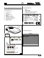
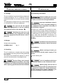
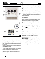
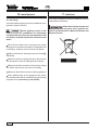
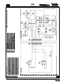
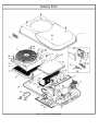
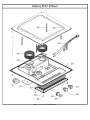
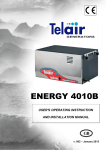
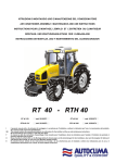
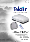
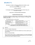
AIR CONDITIONER
12 VOLT
GB
INSTALLATION AND USER MANUAL
VERS. 001
GB
Via E. Majorana , 49 48022 Lugo (RA) ITALY
“CE” COMPLIANCE STATEMENT
Under Machine Directive 89/392/EEC, attachment II A
We hereby represent that the air conditioner, the data concerning which appear
below, has been designed and built to correspond to the essential safety and
health requirements laid down by the European Directive on Machine Safety.
This statement shall not be valid any longer if any changes are made on the
machine without our written approval.
Machine: AIR CONDITIONER
Model:
ICEBERG 5012
Serial number: ………………………...
Directive of reference:
Machine Directive (89/392/EEC) in version 91/31/EEC
Low Voltage Directive (73/23/EEC)
Electro-magnetic Compatibility (89/336/EEC) in version 93/31/EEC
Harmonised standards applied, especially: EN 292-1; EN 292-2; EN 60204-1
DATE ……03/01/2000…….
THE PRESIDENT
-2-
GB
CONTENTS
1 FOREWORD .................................................................................................................... pag. 4
1.1 Purpose and scope of this manual ............................................................................ pag. 4
1.2 Symbols and Definitions ............................................................................................ pag. 4
1.3 General Information ........................................................................................... pag. 4
2 AIR CONDITIONER IDENTIFICATION DATA ................................................................. pag. 5
2.1 Components ............................................................................................................... pag. 5
2.2 Identification plate ........................................................................................................ pag. 5
2.3 Technical features ....................................................................................................... pag. 5
3 SHIPPING, HANDLING, STORAGE ................................................................................. pag. 6
3.1 Storage ........................................................................................................................ pag. 6
3.2 Weight ......................................................................................................................... pag. 6
3.3 Handling ...................................................................................................................... pag. 6
4 INSTALLATION ................................................................................................................. pag. 6
4.1 Preliminary information ............................................................................................... pag. 6
4.2 Installation ................................................................................................................... pag. 6
4.2.1 Using the ventilation portholes .................................................................................... pag. 7
4.2.2 Opening a new hole .................................................................................................... pag. 7
4.2.3 Power supply cable ..................................................................................................... pag. 8
4.3 Positioning the air conditioner ..................................................................................... pag. 9
4.4 Electric connection of air conditioner ........................................................................ pag. 10
4.5 Installing the diffuser ................................................................................................. pag. 10
5 USER INSTRUCTIONS .................................................................................................. pag. 11
5.1 Foreword ................................................................................................................... pag. 11
5.2 Preliminary checks ................................................................................................... pag. 11
5.3 Air diffusion outlets .................................................................................................... pag. 11
5.4 Control panel ............................................................................................................. pag. 11
5.5 Turning on ................................................................................................................. pag. 11
5.6 Ventilation .................................................................................................................. pag. 12
5.7 Turning off ................................................................................................................. pag. 12
5.8 Safety rules ............................................................................................................... pag. 13
5.9 Some problems and how to solve them ................................................................... pag. 13
6 MAINTENANCE .............................................................................................................. pag. 14
7 DISPOSAL ....................................................................................................................... pag. 14
ICEBERG 5012 WIRING DIAGRAM ................................................................................. pag. 15
EXPLODED VIEW ............................................................................................................. pag. 16
SPARE PART LIST ........................................................................................................... pag. 17
-3-
GB
1
FOREWORD
1.2 Symbols and Definitions
This means that you must pay at-
MANUAL Refer carefully to this manual
before performing any operation on the air conditioner.
1.1 Purpose and scope of this manual
This manual has been drawn up by the Manufacturer in order to provide basic information and instructions for performing every operation for servicing and using the air conditioner in a proper and
safe manner.
It is an integral part of the conditioner equipment
should be kept clean and safe throughout its
working life.
It must follow the conditioner if the latter is installed
on a new vehicle, or if its ownership changes hands.
The information in this manual is addressed to the
personnel which must install the air conditioner, and
to all those involved in its maintenance and use.
This manual sets out the purpose the machine was
designed for, and contains all the information required to guarantee that it is used in a safe and
proper fashion.
Constant attention to the instructions laid down here
will guarantee the safety of the user, economy and
longer life of the machine.
To facilitate reference, this manual has been subdivided into chapters which specify the main notions; for quick consultation, refer to the table of
contents.
The most important parts of the text are in bold
letters and preceded by symbols described below.
Please read the contents of this manual carefully.
This is the only way to ensure that the air conditioner will work properly through time and be reliable, while safeguarding people and things.
Note: The information contained in this publication
was correct at the time it went to print, but may be
modified without advance notice.
-4-
tention to avoid serious consequences which might
lead to the death of the operators or at least to possible damage to their health.
This means a situation which
could take place during the lifetime of a product,
system or installation, and which is considered to
be hazardous in terms of damage to people, property, the environment or financial loss.
This means you must pay attention in order not to incur serious consequences
which might lead to damage to material goods, such
as resources or the product itself.
Especially important instructions.
The drawings are only provided by way of example.
Even though the machine you actually have may
differ from the illustrations contained in this manual,
safety and information about the same are guaranteed.
The manufacturer, as part of his policy of constant
development and updating, may effect changes
without providing advance notice.
1.3 General Information
The ICEBERG 5012 air-conditioner has been
designed for installation on vehicle roofs. It runs
off a continuous 12 Vdc power supply.
GB
2. AIR CONDITIONER IDENTIFICATION DATA
2.2 Identification label
2.1 Components (fig. 1)
1
2
3
4
5
Model
Machine code
Serial number
Compressor and fans consumption
Coolant gas type and quantity
1
ICEBERG5012
1
2
3
4
5
6
7
8
9
Ventilation grid
Top hood
Identification label
Diffuser
Adjustable air outlets
Ambient air suction grid
Fan speed selector switch
Thermostat control
ON/OFF switch
CODE : 01625
S.N.000801005
Refrigerating yeld : ............... 1,3 KW
Voltage : ............................... 12 V D.c.
Inlet Power : (cooling) .... 420-500 W
Gas .................................... g.440 R134
Weight : ...................................... 31 Kg
2
8
0
1
5 5 6 4
3
4
5
0 0 6 0 4 0 7
1
2
2.3 Technical features
ICEBERG
3
9
Cooling power
Fan speed number
Power supply
Consumption
Absorbed power
Coolant gas
Air circulatio
Diffuser height
Dimensions (HxLxW)
Weight
8
7
5
5012
4500 BTU
2
12 V d.c.
35 - 42 A
420 - 500 W
R 134
200 m3/h
5,5 cm
18x101x62 cm
31 Kg
4
6
1
-5-
GB
3 SHIPPING, HANDLING, STORAGE
3.1 Storage
4
INSTALLATION
4.1 Preliminary information
The air conditioner is protected during shipping by
suitable packaging. The air conditioner must be
stored horizontally, in a covered, dry and ventilated
area.
The packaging is designed so as to allow stacking
of a maximum of 5 (five) air conditioners.
Do not turn the unit upside
down. The right position is the one shown by
the symbol printed on the package ( ) .
Stacking more than 5 air conditioners will not only compromise the integrity of the equipment, but will also be a risk to
personel.
Before installing the air conditioner, it is essential to read these instructions,
in order to avoid errors during installation
Improper installation of the air
conditioners can cause irreparable damage to
the equipment and compromise the safety of
the installation engineer.
Should the air conditioners be installed in a manner which does not comply with the instructions in
this manual, the Manufacturer shall be held blames
for malfunctions or for the safety of the air conditioner, under D.M. 89/392/EEC. Furthermore, he
shall be held blameless for any damage or injury to
persons
or things.
3.2 Weight
Weight without packing.
ICEBERG 5012
Kg 31
Installation must be performed
by qualified and properly trained personnel
only.
4.2 Installation
3.3 Handling
The air conditioners, complete with their packaging, can be moved using common lifting and transport vehicles.
The boxes are provided with spacers in order to
allow for the introduction of transpallet forks.
During lifting and transport,
comply with accident prevention and safety
regulations. Use lifting and transport equipment
with a capacity greater than the load to be lifted.
-6-
Before starting to install, you
must disconnect all the power supply of the
vehicle
Positive battery pole
Lack of compliance with these
instructions implies a risk of electrical shock.
Before going onto the roof of
the vehicle, you must make sure that it has been
designed to be walked on. Check with the person who equipped the vehicle. Otherwise, you
will have to prepare suitable scaffolding.
GB
In order to install the air conditioner, you must first
make sure the roof of the vehicle is able to hold its
weight. If not, reinforce it. Choose a central, level
and flat area on the roof. Make sure that no obstacle
inside the vehicle can hinder fastening of the diffuser
[Fig.1 ref. 4] and the exit of the cooled air from the
adjustable outlets [Fig. 1 ref. 5].
Remove existing rooflight and sealants making sure
roof surface is clean and even [Fig. 3 ref. 1] Seal
any screw holes and or cable entrance holes so
that no water can penetrate the roof space, using a
suitable sealent [Fig. 3 ref. 2].
To install the air conditioners, you can choose either of two solutions:
silicone, lining - must not be disposed of in the
open, but in special containers and delivered to
a Waste Collection and Disposal Centre.
All the waste material - glue,
Remuve existing rooflight and use aperture
Cut new aperture.
4.2.1 Using rooflight aperture
You can do so on condition that the aperture of the
rooflight measure of 400 x 400 mm. For the dimensions of the air conditioners and of the holes required to install them, refer to figure 2.
1
180
2
3
400
4.2.2 Opening a new hole
395
615
Choose a flat level position on the vehicle roof
beteween the support structure. Mark the aperture
400 x 400 mm square [Fig. 4 ref. 1].
Carefully cut out the opening on the roof, making
sure that no damage will be caused e.g. cables,
hoses, furniture, fittings. [Fig. 4 ref. 2].
1010
Wear safety goggles and
gloves before using any power tools or handsaws.
Make a reinforcing frame along the perimeter of the
opening. Make a hole on one side in order to lead
the power supply cable through [Fig. 5].
400
620
2
-7-
GB
1
4.2.3 Power supply cable
To power the air conditioner it is necessary to
connect it up with a red-black power lead
having a minimum cross-section of 20 mm2.
One end of the lead must be connected to the “+
and –“ battery terminals while the other end must
reach the air conditioner body on the roof [fig 6].
Before effecting any electrical
2
connections always make sure that the lead
ends are NOT live.
4
6
There are two fuses installed in the conditioner body:
One 50 A fuse for the compressor
One 15 A fuse for the two fans.
The cable must be sheathed so
it can provide proper insulation under any condition of use of the vehicle.
5
-8-
GB
4.3 Positioning the air conditioner
Before positioning the air conditioner on the roof of
the vehicle, spread a sufficient of quantity slow-drying sealant around the edges of the opening.
Take the air conditioner on to the roof of the vehicle [Fig. 7 ref. 2] and position it over the opening
(previously treated with sealant). Remember that
the side with the ventilation grid must face the rear
end of the vehicle. The arrow on Figure 7 shows
the driving direction of the vehicle.
Fix the anchor frame to the air conditioner [Fig. 9
ref. 1] , as shown on Figure 9, using the four relevant screws [Fig. 9 ref. 2] without tightening them
all the way.
Do not crush the foam sealing
too much - it must be at least 10 mm thick
[Fig. 9 ref. 3].
If the lining is crushed too much, this will damage the support of the air conditioner and will
compromise the watertightness of the junction.
The support gasket must be
placed flush with the edge of the hole drilled,
7
8
on the back of the air-conditioning unit [fig. 7
ref. 1].
From within the vehicle, move the air-conditioning
unit until the gasket is flush with the rear section
of the roof opening.
The air ducts may be extended,
[fig. 8], they may therefore be used with roof
thickness 30 to 80 mm. Should the roof be
thicker, longer air ducts are available.
9
-9-
GB
4.5 Installing the diffuser
4.4 Electric connection of air conditioner
After anchoring the air conditioner to the
roof of the vehicle remove the cover and insert the “+ –“ leads (coming from the battery)
into the conditioner; pass the wires through the
two sealed fairleads [fig. 10 ref. 1]. Link the two
“+ –“ leads to the supplied connector [fig. 10 ref.
2]. CAUTION: DO NOT INVERT POLARITY.
Fit connector “A” onto connector “B” [fig. 10 ref.
3] and make sure that it is locked in place properly. Then tighten the two fairleads [fig. 10 ref. 1]
to lock the leads themselves in place. Replace
the cover and fix it in place with the screws after
making sure that it is fitted in its seat properly
[fig. 10 ref. 4].
Fit the multi-pole cable connector [Fig. 11 ref. 2]
coming from the diffuser into the connector of the
conditioner [Fig. 11 ref. 1]. Fit both connectors,
pressing until they are firmly fastened.
11
Extend the air ducts [fig. 13 ref. 1] by 1 cm beyond the roof thickness and fit them between the
diffuser [fig. 12ref. 2] and the air conditioner openings [fig. 12 ref. 3], Fasten the diffuser to the frame,
using the relevant four screws [fig. 12 ref. 4]. Fit
the air ducts [fig. 12 ref. 1] between the diffuser
[fig. 12 ref. 2] and the linings [fig. 12 ref. 6]
10
10
12
- 10 -
GB
5. USER INSTRUCTIONS
5.1 Foreword
The Manufacturer shall not be
held liable for any damage due to the air conditioner not working.
The ICEBERG air conditioner is essentially made
up of four sections:
• compressor: circulates the coolant gas through
the system and increases its temperature.
• condenser: cools the coolant, causing it to pass
from a gaseous to a liquid state.
• injector: has the function of transforming the
coolant from a liquid to a gaseous state.
• evaporator: takes in the gas in its gaseous state,
cooling the air that surrounds it. The cooled air
is diffused into the interior of the vehicle by an
adjustable-speed fan.
Air temperature is regulated by a thermostat.
Before starting the conditioner, when the vehicle has
been exposed to direct sunlight for some time open
all the doors and windows to dissipate the
accumulated interior heat before switching on the
air conditioner. Once the in-vehicle temperature is
the same as outdoor temperature re-close all the
doors and windows and start the air conditioner:
open doors and windows only in case of need.
To maximise air conditioner efficiency point one of
the cool air outlet vents towards the door so that if
the latter is opened the hot outdoor air will not enter
the vehicle.
5.2 Preliminary checks
Before turning the air conditioner on, you must perform a few simple operations.
Make sure that the condensate drainage system
is not clogged [Fig. 13 ref. 5].
Check that the battery is charged.
Make sure that nothing is preventing the air from
circulating freely inside the ventilation conduits and
outlets. The outside ventilation grids must always
be free for the air conditioner to be truly efficient.
5.3 Air diffusion outlets
The outflow diffuser panel [fig. 1 ref. 4] has three
cooled air outlet vents.
Each outlet is provided with two mobile baffle plates
which allow you to choke and direct the air jet [Fig.
13]. Press on the baffle plates to choke the air jet
until you close it completely off. Turn the baffle plates
to point the air jet in any direction.
13
5.4 Control panel (Fig. 14)
Fan speed selector switch [Fig. 14ref. 2.
Ventilation / cooling selector switch with thermostat
[Fig. 14 ref. 1].
ON/OFF switch [Fig. 14 ref. 3].
5.5 Turning on
The air conditioner is provided
with an environmental thermostat, with a
minimum working temperature of 18°C (+/-1°C).
Below this temperature the thermostat will
not enable operation of the compressor, thus
preventing the risk of ice forming inside the
air conditioner; the fans remain enabled.
The air conditioner is switched on by turning the
ON/OFF switch [fig. 14 ref. 3] to the “ON” position
and then turning the thermostat dial [fig. 14 ref. 1]
clockwise and setting it to the desired
temperature.
The thermostat keeps the temperature you have
chosen constant, and does so automatically, turning the air conditioner compressor on and off.
- 11 -
GB
2
1
3
To use the conditioner more efficiently, we suggest
you perform the following operations:
First choose Maximum Cool and the third ventilation speed.
When you have reached the temperature you
want, choose the first ventilation speed, then turn
the thermostat knob counter-clockwise until the
compressor goes off (you can tell this has happened
when the noise diminishes).
Night-time ventilation speed can be adjusted to
reduce noise levels.
5.6 Ventilation
When you wish to circulate air around the vehicle
without actually cooling it proceed as follows:
1
Rotate the thermostat dial [fig. 14 ref. 1] anticlockwise as far as it will go.
Press the ON/OFF switch [Fig. 14 ref. 3] to position it
Choose the ventilation speed required [Fig. 14 ref.
2].
3
2
5.7Turning off
To turn the air conditioner off, position the switch
14
The temperature scale is marked by a series of dots
of different sizes.
The minimum cooling value is marked by the smallest dot, the maximum cooling value is marked by
the largest [Fig. 14 ref. 1].
The thermostat controls the temperature automatically, but the speed of the fan must be set manually
by the user.
Set the fan speed required on the relevant selector
switch [Fig. 14 ref. 2].
To use the air conditioner in the most effective
manner, we suggest the following settings:
Minimum speed - Minimum cool (night-time)
Maximum speed - Maximum cool
- 12 -
[Fig. 14 ref. 3] on the
position.
After having turned the air conditioner off, either using the thermostat knob
or the ON-OFF switch, wait at least three minutes before turning it back on again, so the coolant can stabilise its pressure. Lack of compliance with this rule may damage the compressor irreparably.
GB
5.8 Safety rules
Before anything else, check if:
Always use leads of a suitable cross-section (20
mm2) for connection to the battery.
Wires/leads which are too
thin may heat up as the current passes
through them, thus creating a fire risk!! Never
attempt to put out an electrical fire with water.
Never use the air conditioner near flammable liquids.
Never use the air conditioner for any purpose other
than that designed for by the Manufacturer.
Never modify or tamper with any part of the air
conditioner.
Use only original spare parts.
Maintenance and repairs must be performed by
specialised personnel only.
Installation must only be performed by qualified
personnel.
Never allow animals or children near the equipment.
Never put your hands inside the ventilation grids.
Never put foreign objects into the ventilation outlets.
Should the air conditioner be subject to an impact, have it checked by specialised personnel before using it again.
In case of fire, never open the top lid of the air
conditioner, but use a standard non water based
fire extinguisher.
Do not use water to put the fire out.
5.9 Some problems and how to solve them
Unsatisfactory performance of the air conditioner
will usually be due to improper use rather than to
malfunction check.
The conditioner is not too small compared to the
volume of air it has to condition.
The walls of the vehicle are sufficiently insulated.
The doors are not opened too frequently.
There are not too many people inside the vehicle.
The voltage is less than 230 V.
the power supply has dropped below 205 V;
the ventilation grids are jammed;
the air diffusion outlets are open.
1) The air conditioner will not start up:
Check whether the ON/OFF switch is in its ON
position [Fig. 14 ref. 3], the thermostat is in its allcold position [Fig. 14 ref. 1]
• Check that the red (+) and the black (-) power
leads are connected to the battery correctly. If
polarity has been inverted disconnect the wires,
replace the fuses in the conditioner and then
reconnect correctly [fig. 10 ref. 5].
• Then check that the battery is charged.
2) The compressor does not work:
• For the compressor to function the thermostat
[fig. 14 ref. 1] must be in the cold position.
• Check the fuse (50 A) inside the conditioner.
3) The fans do not work:
• Check that the ON/OFF switch [fig. 14 ref. 3]
is in the ON position.
• Check the fuse (15 A) inside the conditioner.
4) The condenser fan does not work:
Make sure that the condenser fan is not hindered
by foreign matter.
5)The air conditioner performs poorly:
If the air conditioner performs poorly, you must
clean the air filter, the condenser and the evaporator using specific detergents. We suggest you clean
these before using the air conditioner when it has
not been used for a long time. If the air conditioner
still does not return to its original performance after
cleaning of the exchangers, you must have the
coolant gas level checked by a pecialist.
Here is a list of possible problems and how to solve
them.
- 13 -
GB
6.
MAINTENANCE
If you have to dispose of the air conditioner, refer to
a specialised workshop.
6.1 Servicing
Accurate inside cleaning of the air conditioner is important to keep it efficient.
Before gaining access to the
interior of the air conditioner it is absolutely
essential that the leads be disconnected from
the battery and that all parts be allowed to cool
down.
Take off the outside cover and spray the proper
detergent on the heat exchangers (evaporator and
condenser), and then rinse to remove all debris.
Make sure that the drainage holes are free [fig.
12 ref. 5].
Make sure that the sealing lining is in good condition and that no water is leaking into the vehicle.
Make sure that the insulation of the electric cables
are whole and remove any trace of humidity.
Make sure that all the screws are firmly tightened.
When putting away in the garage for the winter,
you should protect the air conditioner from dust using
a special cover (accessory code 00639).
- 14 -
7. DISPOSAL
All the waste material must not
be disposed of in the open, but in special containers and delivered to a Waste Collection and
Disposal Centre.
1
2
3
4
5
6
7
8
DIFFUSER
ON/OFF switch
Fan speed selector switch
Thermostat
Connector
Evaporator electric fan
Condenser electric fan
Armored resistor 1.5 omh/ 50W
Relay 40 Amp
9
10
11
12
13
14
CONDITIONER
Relay 70 Amp
Compressor
Max. pressure switch
15 Amp fuse
60 Amp fuse Compressor
Feeding connection terminal
ICEBERG 5012 WIRING DIAGRAM
GB
15
- 15 -
Iceberg 5012
(Tav. 1 - Vers. 13 del 08/02/2005)
Pos Code Q.tà
Descrizione/Description
Dèsignation/Bezeichnung
Denomination/Descripcion
1
00347 N.1
Coperchio
Lid
Couvercle
Deckel
Kap
Tapa
2
00368 N.2
Etichetta
Label
Etiquette
Etikett
Etiket
Etiqueta
3
00022 N.1
Ventola
Fan
Ventilateur
Lufterrad
Ventilator
Ventilador
4
00198 N.3
Distanziatore
Spacer
Entretoise
Distanzstuck
Afstandshouder
Separador
5
01423 N.1
Plenum condensatore
Cond.plenum
Plénum condens.
Plenum Kondensator
Distributieruimte condensator
Plenum condensador
6
01386 N.1
Condensatore
Condenser
Condenseur
Kondensator
Condensator
Condensador
7
01619 N.1
Pressostato
Pressure switch
Pressostat
Druckschalter
Drukverschilschakelaar
Presòstato
8
01590 N.1
Scatola posteriore evaporatore
Rear evapor. box
Boîtier arr. évap.
Hinterer Kasten des Verdampfers
Voorste kast Verdamper
Caja delantera evaporador
9
01864 N.1
Scatola anteriore evaporatore
Front. evapor. box
Boîtier av. évaporateur
Vorderer Kasten des Verdampfers
Voorste kast verdamper
Caja delantera evaporador
10
01586 N.1
Coperchio
Lid
Couvercle
Deckel
Kap
Tapa
11
01385 N.1
Evaporatore
Evaporator
Evaporateur
Verdampfer
Verdamper
Evaporador
12
00021 01
Ventola
Fan
Ventilateur
Lufterrad
Ventilator
Ventilador
13
00093 N.1
Relè 12V 70A
Relay 12V 70A
Relais 12V 70A
Relais 12V 70A
Relais 12V 70A
Rele 12V 70A
14
00513 N.1
Rele' 12V 40 Amp.
Relay 12V 40 Amp
Relais 12V 40A
Relais 12V 40 Amp.
Relais 12V 40 Amp.
Relé 12V 40 Amp.
15
00235 N.1
Blocchetto 4 vie
4-way block
Bloc à 4 voies
4-Wege-Block
4-weg blokje
Bloque de 4 vias
16
01608 N.4
Connettore Faston 10mmq
Connector Faston 10mmq
Connecteur Faston 10mmq
Verbinder Faston 10mmq
Connector Faston 10mmq
Conector Faston 10mmq
17
01885 N.1
Motocompressore completo
Moto-Compressor complete
Compresseur complete
Kompressor complete
Compressor complete
Compresor completo
18
00928 N.4
Antivib.25x20 6M MF SH 60 ANTIOLIO
Vib.damper ANTIOIL
Anti-vibr. 25x20 6M MF SH 60 ANTIHUILE
Schwing.dämpf.25x20 6M MF SH 60 ÖLABW.
Trillingsdemp.25x20 6M MF SH 60 OLIEWEREND
Silenc..25x20 6M MF SH 60 ANTIACEITE
20
01588 N.1
Staffa SX compressore
SH Bracket
Bride S.
Bügel, re
beugel SX
Estribo ISC
20
01587 N.1
Staffa DX compressore
RH Bracket
Bride D.
Bügel, re
Rechterbeugel
Estribo DER
21
01521 N.1
Scatola di comando in plastica
Plastic control box
Boîtier de commande
Schaltkasten
Besturingskast
Caja de mando
22
01472 N.2
Connettore SB50
Connector SB50
Connecteur SB50
Verbinder SB50
Connector SB50
Conector SB50
23
01118 N.2
Dado DIN 46320
Nut DIN 46320
Ecrou DIN 46320
Mutter DIN 46320
Moer DIN 46320
Tuerca DIN 46320
23
01117 N.2
Pressacavo PG11
Cable gland PG11
Serre-câble SKINTOP PG11
Kabelschelle PG11
Kabelklem PG11
Prensa cable PG11
24
00348 N.1
Fondo
Bottom
Fond
Boden
Onderkant
Fondo
25
01580 N.1
Convogliatore
Conveyor
Convoyeur
Leitblech
Geleider
Transportador
26
00997 ML1,9 Aerstop
Rubber strip
Joint caoutchouc
Aerstop
Aerstop
Aerstop
27
01620 ND1
Cablaggio
Harness
Câblage
Verkabelung
Bedrading
Cableado
28
01458 N.4
Distanziatore
Spacer
Entretoise
Distanzstück
Afstandshouder
Separador
30
01869 N.1
Tegolo di scarico condensa
Conds disch.sheet
Pièce métall. évacuation condensation
Kondenswasserablass
Condensafvoerplaat
Teja de descarga condensaciòn
31
01629 N.3
Resistenza 1 OHM 50W
Resistor 1 OHM 50W
Résistance 1 Ohm 50W
Widerstand 1 OHM 50W
Weerstand 1 OHM 50W
Resistencia 1 OHM 50W
32
01602 N.1
Fusibile 50A
Fuse 50A
Fusible 50A
Sicherung 50A
Zekering 50A
Fusible 50A
33
01607 N.1
Fusibile 15A
Fuse 15A
Fusible 15A
Sicherung 15A
Zekering 15A
Fusible 15A
34
01600 N.1
Portafusibile
Fuse holder
Tableau/fusible
Sicherungshalter
Zekeringhouder
Porta fusible
35
01601 N.1
Coperchio fusibile
Fuse cover
Covercle fusible
Dekel Sicherung
Zekeringkap
Tapa fusible
36
01605 N.1
Portafusibile
Fuse holder
Tableau/fusible
Sicherunghalter
Zekeringhouder
Porta fusible
37
01606 N.1
Coperchio fusibile
Fuse cover
Couvercle fusible
Deckel Sicherung
Zekeringkap
Tapa fusible
38
01821 N.1
Piastrina di fissaggio relè
Relay fastening plate
Plaquette fix.relais
Relais Befestingungsplatte
Bevestigingsplaatje relais
Place de fijaciòn Rele
39
01603 N.1
Piastrina di fissaggio porta fusibile
Fuse holder fastening plate
Plaquette fix. Tableau/fusible
Befestigungsplatte Sicherungshalter
Bevestigingsplaatje Zekeringhouder
Placa de fijaciòn porta fusible
40
01453 N.1
Filtro di rame GR.30
Copper filter GR.30
Filtre en cuivre GR29
Kupferfilter GR.30
Koperen filter GR.30
Filtro en cobre GR.30
41
01501 N.1
Regolatore 025
Regulator 025
Régulateur 025
Regler 025
Regelaar 025
Regulador 025
Iceberg 5012 diffuser
(Tav. 2 - Vers. 13 del 08/02/2005)
Pos Code Q.tà
Descrizione/Description
Dèsignation/Bezeichnung
Denomination/Descripcion
50
01404 N.1
Diffusore
Diffuser
Diffuseur
Luftverteiler
stromingsspreider
Difusor
51
00151 N.3
Bocchetta
Mouth
Bouche
Düse
Mondstuk
Boquilla
52
01450 N.1
Aeratore da incasso
Built-in aerator
Aérateur à encastrer
Einbaulüfter
Inbouwventilator
Ventilador empotrado
53
00301 N.1
Deviatore
Deflector
Déviateur
Abzweiger
Omschakelaar
Desviador
54
00302 N.1
Interruttore
Switch
Interrupteur
Schalter
Schakelaar
Interruptor
55
00439 N.1
Termostato
Thermostat
Thermostat
Thermostat
Thermostaat
Termòstato
56
01552 N.4
Rivetto autobloccante
Self-locking rivet
Rivet auto-bloquant
Niet selbstsichernd
Zelfborgendeklinknagel
Remache de autobloqueo
57
00134 MQ.0,04 Filtro poliuretano rigido
Stiff polyurethan filter
Filtre polyuréth. Rigide
PUR-Filter steif
Onbuigzaam polyurethaan filter
Filtro poliuretano rigido
58
01568 N.2
Guarnizione
Gasket
Joint
Dichtung
Afdichting
Junta
59
05566 N.1
Manopola diffusore
Diffuser Knob
Poignée diffuseur
Drehgriff Luftverteiler
Knop stromingsspreider
Mango difusor
60
01659 Mt.0,1
Tubo aria calda
Hot air pipe
Tuyau air chaud
Warmluftleitung
Wormeluchtslang
Tubo aire caliente
61
01773 N.1
Etichetta
Label
Etiquette
Etikett
Etiket
Etiqueta
62
01883 N.1
Cablaggio
Harness
Câblage
Verkabelung
Bedrading
Cableado
63
00373 N.4
Vite UNI 5739 M6x60
Screw UNI 5739 M6x60
Vis UNI 5739 M6x60
Schraube UNI 5739 M6x60
Schroef UNI 5739 M6x60
Tornillo UNI 5739 M6x60
63
05522 N.4
Vite UNI 5739 M6x100
Screw UNI 5739 M6x100
Vis UNI 5739 M6x100
Schraube UNI 5739 M6x100
Schroef UNI 5739 M6x100
Tornillo UNI 5739 M6x100
64
01160 N.1
Etichetta
Label
Etiquette
Etikett
Etiket
Etiqueta
65
01589 N.1
Lamiera diffusore
Diffuser sheet
Pièce métallique diffuseur
Luftverteilungsblech
Plaat stromingsspreider
Chapa difusor
GB
General terms of warranty
Telair guarantees that its products are without faults or
defects in their material and/or construction.
The effects of the warranty are understood to be limited
to the right to obtain replacement or repair free of cost of
any part which should turn out to be defective, within 12
months from the date of purchase of the product and in
Telair’s opinion.
It is understood that the purchaser has no right
whatsoever:
to terminate the contract;
to claim damages for people or things;
to demand an extension of the warranty in case of any
product defect or malfunction.
Any transport charges are on the account of the purchaser,
as well as any expenses for on-site checks requested by
the purchaser and accepted by Telair.
The warranty shall be valid only if the customer is able to
show a document evidencing the date of purchase (invoice
or receipt).
This document must be kept whole and must be submitted
to the Telair after-sales centre when asking for operation
under warranty.
- 21 -
GB
NOTES
- 22 -
GB
NOTES
- 23 -
IN EUROPE:
GREAT BRITAIN - SCAN TERIEUR LTD
30, The Metro Centre, Tolpits Lane - Watford,
Herts - England - WD18 9XG
Tel. 01923 800353 - Fax 01923 220358
ITALY
Via E.Majorana 49
48022 LUGO( RA )
Tel. + 39 0545 25037
Fax.+ 39 0545 32064
E-mail: [email protected]
www.telecogroup.com
HOLLAND / BELGIUM - KARMAN TRADING
Lagewed 54 – 3849 PE Hierden – the Netherlands
Tel. 0341 722450 - Fax 0341 722451
e-mail: [email protected]
web site: www.karmantrading.nl
FRANCE - BLEYS JEAN-PHILIPPE
19, Rue de la Parcheminerie
18700 Aubigny sur Nere - France
Tel.02 48580367 – Fax 02 48583585
e-mail: [email protected]
Service Technique France : 06 83 31 44 05
ESPAÑA - NAUCCA CARAVANING, S.A.
Poligono Industrial CAN ROQUETA 2 – Calle Can Lletget,2
08202 Sabadell (Barcelona) - España
Tel. 00 34 937 457 054 - Fax. 00 34 937 254 484
e-mail: [email protected]
ÖSTERREICH – TELECO GmbH
82041 Deisenhofen - Deutshland
Tel. 0049 8031 98939 - Fax. 0049 8031 98949
e-mail: [email protected]
www.telecogroup.com
ZIMMER
TECHNIK FŐR MOBILE FREIZEIT
Raiffeisenstr, 6
64347 Griesheim
Tel. 06155 797873 - Fax. 06155 797871
[email protected]
IN DEUTSHLAND
TELECO GmbH
82041 Deisenhofen Tel. 0049 8031 98939 - Fax. 0049 8031 98949
e-mail: [email protected]
www.telecogroup.com
Service für Teleco Anlagen in Deutschland:
09001000690
Service für Teleco Anlagen in Österreich:
0900949470
Foto e disegni non contrattuali - Les photos et les dessins ne sont donnés qu’à titre indicatif.
We reserve the right to make technical changes without prior notice - Fotos und Zeichnungen nicht vertraglich.
Foto’s en tekeningen niet contractueel - Fotos y planos no indicados en contrato