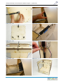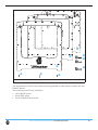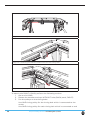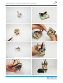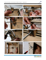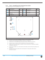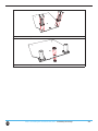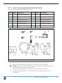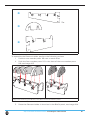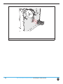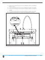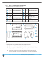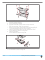
1
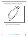
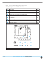
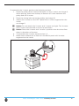
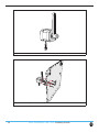
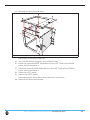
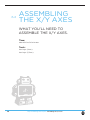
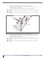
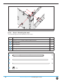
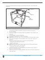
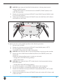
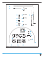
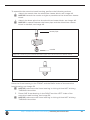
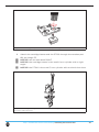
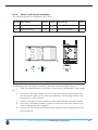
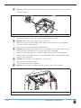
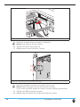
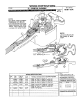
3Dkanjers: Wij gaan een 3D-printer bouwen
The fast, easy to use, Open-source 3D printer
3Dkanjers Bouwinstructie
Ultimaker Original +
Versie 1.0 Assembly
instructions
© 2014 | 3Dkanjers
3Dkanjers: Wij gaan een 3D-printer bouwen
Wij gaan een 3D-printer bouwen
Wat gaan we doen?
Met je groepje bouw je jullie deel van de 3D-printer.
Ga eerst samen zitten en bespreek wat er moet gebeuren.
Daarna verdeel je de taken.
Als iedereen weet wat de bedoeling is, ga je aan de slag.
Aan het eind vertel je in de groep wat je hebt gedaan.
Zorg ervoor dat je verhaal duidelijk is, want iedereen moet weten waar jullie zijn gebleven.
Wat leer je hiervan?
Als je (een deel van) de 3D-printer hebt gebouwd:
• kun je zelfstandig informatie vinden over de 3D-printer;
• begrijp je de Engelse termen die worden gebruikt als je wilt gaan printen op een 3Dprinter;
• weet je hoe een 3D-printer werkt en uit welke onderdelen de 3D-printer bestaat;
• kun je later eventuele problemen met de 3D-printer zelf oplossen.
Wat heb je nodig?
De bouwbeschrijving van de 3D-printer. Deze vind je in hoofdstuk 6.
De onderdelen uit de doos. In de bouwbeschrijving staat precies per onderdeel wat je
nodig hebt om het te kunnen bouwen.
Gereedschap. In de bouwbeschrijving staat precies wat je nodig hebt aan gereedschap.
Bouwtips en Bouwinspectie. Voor elke stap in het bouwproces vind je aanvullende tips op
een apart blad. Je vind hierop ook een aantal punten waarmee je kan controleren of alles
goed gegaan is.
Hoe ga je het aanpakken?
De 3D-printer bestaat uit een aantal onderdelen (bijvoorbeeld het frame, de Z-stage en de
Material feeder). Per onderdeel vind je in de bouwbeschrijving een uitgebreide uitleg.
Zoek je onderdeel op en lees de beschrijving met elkaar goed door. Bespreek samen wat
er moet gebeuren en verdeel de taken. Ga dan pas de benodigde onderdelen bij elkaar
zoeken.
Tips?
• Gebruik bij het bouwen niet alleen de plaatjes als voorbeeld. Lees de bijbehorende
beschrijvingen.
• Je kan de Engelse teksten vertalen met Google translate of een woordenboek.
• Gebruik de juiste maat boutjes. De maten staan erbij.
• Gooi niets weg. Misschien hebben we het later nog nodig.
Wat is de planning?
In de werkplanning die je van de leerkracht krijgt, staat precies beschreven welk
onderdeel je met jouw groep gaat maken en hoeveel tijd je hiervoor hebt.
© 2014 | 3Dkanjers
Ultimaker Original+ Assembly manual
Dear customer,
Thank you for purchasing the Ultimaker Original+ DIY kit and welcome to our community!
This assembly manual will guide you through the build process step by step.
During the excitement of the build process you learn more and more. This will
help you understand the workings of a 3D printer even better and give you the
opportunity to get the most out of your Ultimaker.
Besides this assembly manual there’s also a user manual available online:
www.Ultimaker.com/pages/support/manuals
www.Ultimaker.com/forum
Visit YouMagine for fun projects and free printable models: www.youmagine.com
Happy building and printing and we’ll be in touch!
Team Ultimaker
Contact information
We would love to hear from you. We are easy to reach and enjoy answering all
your questions. Technical assistance, sales enquiries or general information, we
are there for you. Find the information below to contact us.
General
Support
Sales
Marketing/PR
[email protected]
[email protected]
[email protected]
[email protected]
Phone
+31 (0)345 712 017
Meet us online at:
2
Table of contents
1
Introduction
1.1
Product description
1.2 Used symbols
2
5
5
5
6
3
Precautions and safety instructions
7
4
Preparation before assembling
4.1 Engraving
4.2 Sanding
8
8
8
5
What to expect reading the assembly instructions
5.1 Structure of the assembly instructions
8
8
6
Assembling the Ultimaker Original+
10
the frame
6.1.1.
6.1.2.
6.1.3.
6.1.4.
6.1.5.
6.1.6.
10
11
12
16
19
20
25
Step
Step
Step
Step
Step
Step
6.2.1. Step
blocks
6.2.2. Step
6.2.3. Step
6.2.4. Step
1: Inserting the ball bearings
2: Mounting the limit switches
3: Assembling the X and Y motor
4: Preparing the BOTTOM panel
5: Assembling the ‘cube’-shaped frame
6: attaching various parts
1: Assembling the FRONT, BACK, RIGHT, LEFT slider
2: Attaching the claws
3: Mounting the caps
4: Mounting the axes
29
30
32
36
6.3.1. Step 1: Assemble the extrusion head housing
6.3.2. Step 2: cooling fan assembly
6.3.3. Step 3: attaching the housing on the XY frame
43
51
53
6.4.1. Step 1: Assembling the Aluminium base plate.
58
3
6.4.2. Step 2: Assembling the Heated bed PCB
6.4.3. Step 3: Connecting the PCB to the Baseplate
60
62
6.4.7. Step 7: greas it up
69
6.5.1.
6.5.2.
6.5.3.
6.5.4.
Step
Step
Step
Step
1: drive mechanism main body assembly
2: drive bolt assembly
3: clamp assembly
4: attaching the feeder to the machine
71
73
75
80
6.6.1.
6.6.2.
6.6.3.
6.6.4.
6.6.5.
6.6.6.
6.6.7.
Step
Step
Step
Step
Step
Step
Step
1: mounting the electronic circuit board
2: connecting the heater and Heated Bed
3: connecting the print head electronics
4: connecting the limit switches
5: connecting the motors
6: mounting the electronics cover
7: strain relief
84
85
87
87
87
89
89
6.7.1. Step 1: assembling the UltiController
6.7.2. Step 2: connecting the controller
7
Usage of the Ultimaker Original+
7.1.1.
4
Slicer software
93
95
96
97
1
Introduction
1.1
Product description
The parts of the Ultimaker Original+ can only be used for assembling the
Ultimaker Original+. An assembled Ultimaker Original+ can only be used for
Ultimaking B.V. cannot be held liable for any damage caused by improper,
incorrect or unwise use. Please read this manual completely and make sure
1.2
Used symbols
1 Warning! A warning indicates the risk of (serious) damage to the user or
the product if the user does not carry out the procedures with care.
1 Caution! A comment makes the user aware of possible problems.
5 Notice: A notice makes the user aware of convenient functions and
additional options.
5
2
2.1
Product description
Name:
Model/type:
Year of production:
Dimensions (W x D x H)
Mass
Power source
Operating system:
Speed:
Ultimaker Original+
Revision 4
2014
357 x 342 x 388mm
9 kg
Accuracy:
110V or 230 V
Windows, MAC and Linux
Max. head travel speed between
30mm/s - 300mm/s.
Positioning < 0.05mm
Technology:
Ambient Operating Temperature:
Storage Temperature:
FFF (Fused Filament Fabrication)
15° - 32° C
0° - 32° C
2.2
Environmental conditions
The Ultimaker Original+ can only be used in a dry environment. The product
cannot be used in a humid environment and in an environment with lots of
performance of the product.
6
3
Precautions and safety instructions
Only use original accessories from the manufacturer.
The product should only be used for applications as described by
the manufacturer. All other applications are unprofessional and
considered dangerous. The manufacturer cannot be held liable for
damage resulting from errors, unintended or unprofessional use of
Do not install the product outdoors or in any place where it might
become wet.
Do not install the product in any place that might be exposed to
extreme heat or cold.
Keep the product out of reach of children.
Disconnect the device from all power sources before cleaning it.
Remove the adapter from the power outlet during storms, lightning
and whenever the product will not be used for a longer period of
time.
Install the product as indicated in this manual. If in doubt, consult a
recognized technician and always take account of local installation
codes and regulations.
The product should be kept out of direct sunlight.
The product must not be discarded as unsorted municipal waste, it
must be disposed of separately.
Find out about the options in your region for disposing of the
components, but see whether the product (components) can be
turned in, recycled or reused.
7
4
Preparation before assembling
4.1
Engraving
All panels are marked with the side they belong to.
For all the panels except the FRONT panel and the BOTTOM panel, the
engraving faces. The FRONT panel has the “Ultimaker” engraving facing
outward. The BOTTOM panel has the engraving facing downward.
4.2
Sanding
Before starting the assembly, you may want to sand the panels slightly to
remove any burn marks/blemishes from the laser cutting process. You can also
paint or stain your Ultimaker Original+. Be aware that paint will not cover the
brown cutting edges very well.
5
What to expect reading the assembly
instructions
5.1
Structure of the assembly instructions
Before assembling the Ultimaker Original+, separate sub assemblies have to be built.
The description of every sub assembly in this manual will contain:
• An overview of the needed tools;
• An estimation of the needed time to built the sub assembly;
• The steps;
Every step in this manual will be described using the following structure:
• Cautions and warnings (if applicable);
• The needed parts;
• The actions to perform the step.
To make this manual easy to understand, images are used as much as possible.
8
5.2
In this manual, you will read about FRONT side, BACK side, LEFT side,
image 1:
sides of the Ultimaker Original+
9
6
Assembling the Ultimaker Original+
6.1
ASSEMBLING
THE FRAME
WHAT YOU’LL NEED TO BUILD
THIS SUB ASSEMBLY.
Time:
about 60 to 90 minutes
Tools:
hex key screwdriver (1,5mm)
hex key wrench (2mm)
5.5mm (M3) socket wrench or pliers
10
3Dkanjers Bouwtips en Bouwinspectie Ultimaker Original + (heated bed)
6.1. Assembling the Frame
(pagina 10-27)
Bouwtips
Het bouwen van het frame duurt ongeveer 3 uur en is verdeeld in 3 blokken:
• Blok 1: step 1 en 2
• Blok 2: step 3 en 4
• Blok 3: step 5 en 6
In de bouwbeschrijving van Ultimaker (pagina 10-27) staan zeer belangrijke zaken met
een uitroepteken aangegeven. Lees deze dus ook goed. Loop samen eerst alle pagina’s
door, dan kan je het werk goed verdelen. Hieronder per stap nog een aantal tips.
•
•
•
•
Step 1 (6.1.1.):
o Sla niet met een “gewone” hamer op de “ball bearings”. Gebruik bijvoorbeeld
een rubberen hamer of als je sterk bent je duim.
Step 2 (6.1.2.):
o Schroef de “Limit Switches” niet te hard aan. Heb je de goede boutjes
gebruikt (let op de lengte)?
Step 3 (6.1.3.):
o De “motoren” lijken veel op elkaar en toch zijn ze verschillend. De motor met
het halve asje is in ieder geval voor later (voor de “feeder”).
o Plaats het motortje zo, dat de draadjes die uit de motortjes komen naar
beneden gaan.
Step 5 (6.1.5.):
o Vergeet niet dat het snoertje van de “limit Switch” linksachter (zwarte draad)
achter de zwarte “spacers” van het motortje moet lopen.
o Vergeet de “kabelgootjes” niet (cable ducts)!.
o Gebruik een rubberen hamer om het frame zachtjes in elkaar te zetten.
Bouwinspectie
•
•
•
Zitten er geen “kieren” tussen de framedelen?
Zijn alle boutjes van het frame goed aangedraaid (vast is vast)?
Lopen alle snoetjes naar de onderzijde van de 3D-printer door de kabelgootjes
(cable ducts)?
© 2014 | 3Dkanjers
3Dkanjers Bouwtips en Bouwinspectie Ultimaker Original + (heated bed)
Step 1 (6.1.1.)
Step 2 (6.1.2.)
Step 1 (6.1.1.)
Step 2 (6.1.2.)
Step 1 (6.1.1.)
Step 3 (6.1.3.)
Step 2 (6.1.2.)
© 2014 | 3Dkanjers
3Dkanjers Bouwtips en Bouwinspectie Ultimaker Original + (heated bed)
Step 4 (6.1.4.)
Step 5 (6.1.5.)
Step 4 (6.1.4.)
Step 5 (6.1.5.)
Step 5 (6.1.5.)
Step 5 (6.1.5.)
Step 5 (6.1.5.)
Het resultaat
© 2014 | 3Dkanjers
6.1.1.
Step 1: Inserting the ball bearings
The following parts are needed in this step.
Letter Description
A
B
C
D
E
Qnty.
FRONT panel
1
LEFT panel
1
RIGHT panel
1
BACK panel
1
ball bearings 8mm
8
D
C
B
A
image 2:
E
8x
parts needed for this step
Every panel needed for this step has two corresponding holes.
To place the ball bearings, perform the following actions:
1.
2.
3.
Get a panel.
Place the ball bearings.
Make sure you place the ball bearings as deep as shown in image 3.
Repeat action 1 and action 2 for all panels.
Step 1: Inserting the ball bearings Assembling the frame
11
image 3:
6.1.2.
placing the ball bearings into the panel
Step 2: Mounting the limit switches
Warning! Do not strain the tapped thread on the inside of the switch
housing by putting a lot of force on the bolts. All limit switches are
pre-tapped, you can fasten them directly with M3 bolts, no nuts
required here!
Caution! Note that all wires of limit switches need to be twisted,
The following parts are needed in this step.
Letter Description
A
B
C
D
E
F
G
H
I
12
Qnty.
FRONT panel
1
LEFT panel
1
BACK panel
1
RED wired limit switch
1
BLUE wired limit switche
1
BLACK wired limit switch
1
bolts M3 x 12mm
4
bolts M3 x 16mm
2
washers
2
Step 2: Mounting the limit switches Assembling the frame
C
B
A
G
image 4:
H
D
E
F
I
parts needed for this step
The orientation of the limit switches are engraved on the panels, except for the
FRONT panel.
The machine has 3 limit switches:
• 1 with BLUE wires
• 1with RED wires
• 1 with LONG BLACK wires
Step 2: Mounting the limit switches Assembling the frame
13
To mount the BLUEwired limit switches, perform the following actions:
1.
Place the BLUE wired limit switch as shown in image 5.
2. Attach the BLUE wired limit switch with two bolts M3x12mm.
image 5:
attaching the RED wired limit switches
To attach the RED wired limit switch, perform the following actions:
1.
Attach the REDwired limit switch as shown in image 6.
2. Attach the RED wired limit switch with two bolts M3 x 12mm.
14
Step 2: Mounting the limit switches Assembling the frame
image 6:
attaching the BLUE wired limit switch
To attach the BLACK limit switch with LONG wires, perform the following
actions:
1.
Attach the BLACK limit switch with LONG wires as shown in image 7.
Fine tuning the position will be described in another part of this
manual.
2. Attach the BLACK limit switch with LONG wires.
Use two bolts M3 x 16mm and two washers.
image 7:
attaching the BLACK wired limit switch with LONG wires
Step 2: Mounting the limit switches Assembling the frame
15
6.1.3.
Step 3: Assembling the X and Y motor
The following parts are needed in this step.
Letter Description
A
B
C
D
E
F
G
H
Qnty.
LEFT panel
1
BACK panel
1
motors with long wires and rounded axles
2
Motor spacer
2
M3 washers
8
short timing belts
2
pulleys with a 5mm internal diameter
2
bolts M3 x 25mm
8
A
image 8:
16
B
C
D
E
F
G
H
parts needed for this step
Step 3: Assembling the X and Y motor Assembling the frame
To assemble the Y motor, perform the following actions:
1.
Place the pulley (5mm internal diameter) on the Y motor, see image 9.
When placing, make sure to keep a distance of 1-2mm between the
pulley and the Y motor.
2. Place the timing belt around the pulley, see image 10.
3. Attach the Y motor on the LEFT panel with Y motor engraved on the
inside,
see image 11.
5 Notice: Do not attach the X motor and Y motor too tight. The X motor
and Y motor must be able to move up and down.
5 Notice: Place the X motor and Y motor in position that the wires face
down in direction of the text.
4. To assemble the X motor repeat action 1-2.
5. Make sure to attach the X motor on the BACK panel with X motor
engraved on the inside.
image 9:
placing the pulley on the Y motor axis
Step 3: Assembling the X and Y motor Assembling the frame
17
image 10: placing the timing belt around the pulley
image 11:
18
attaching the Y motor on the BACK panel
Step 3: Assembling the X and Y motor Assembling the frame
6.1.4.
Step 4: Preparing the BOTTOM panel
The following parts are needed in this step.
Letter Description
A
B
C
Qnty.
BOTTOM panel
1
pieces of Velcro
4
bolts M3 x 10mm
4
A
4x
4x
C
E
D
1x
image 12:
B
1x
parts needed for this step
To prepare the BOTTOM panel, perform the following actions:
1.
Move 4 pieces black Velcro through the 4*2 slots of the
Make sure the soft side is facing itself after placing.
Step 4: Preparing the BOTTOM panel Assembling the frame
19
image 13:
6.1.5.
moving black Velcro through the slots
Step 5: Assembling the ‘cube’-shaped frame
The following parts are needed in this step.
Letter Description
A
B
C
D
E
20
Qnty.
panels (TOP, BOTTOM, FRONT, LEFT, BACK and RIGHT)
6
SHORT cable ducts
2
LONG cable ducts
2
blue Scotch tape
1
bolts M3 x 16mm
37
hex nuts 3mm
37
Step 5: Assembling the ‘cube’-shaped frame Assembling the frame
A
B
C
2x
37 x
D
37 x
E
2x
image 14: parts needed for this step
Warning! Be careful not to put any force on the panels because they
once you mount a few more panels.
To assemble to ‘cube’-shaped frame, perform the following actions:
(for action 1-5 see image 15)
1.
Place the BACK panel on the table.
Make sure the markings are facing towards you.
2. Put the TOP panel, with the markings downwards, into the BACK panel.
3. Put the BOTTOM panel into the BACK panel.
4. Put the FRONT panel in the TOP and the BOTTOM panel.
5. Attach the four panels.
Use thirteen bolts M3 x 16mm and thirteen hex nuts 3mm.
5 Notice:
5 Notice: if you attach the hex nuts, it can be helpfull to use some tape
to keep them in position.
5 Notice: make sure no cables get jammed before tightening.
Step 5: Assembling the ‘cube’-shaped frame Assembling the frame
21
image 15:
6.
7.
8.
5
attaching the BACK, TOP, BOTTOM and FRONT panel
(for action 6-8 see image 16)
Place a SHORT cable duct on the RIGHT side of the BACK panel.
Fold the SHORT cable duct.
Tape the folded SHORT cable duct (to keep it folded).
Notice: make sure the blue Scotch tape can be removed easily.
image 16: attaching and folding the SHORT cable duct
(for action 9-14 see image 17)
9. Place a LONG cable duct on the RIGHT side of the FRONT panel and
check if it is alligned correctly
10. Fold the LONG cable duct.
11. Tape the folded LONG cable duct (to keep it folded).
5 Notice: make sure the blue Scotch tape can be removed easily.
12. Place the RIGHT panel.
13. Attach the RIGHT panel.
Use twelve bolts M3 x 16mm and twelve hex nuts 3mm.
22
Step 5: Assembling the ‘cube’-shaped frame Assembling the frame
14. Remove the blue Scotch tape.
image 17:
15.
16.
17.
18.
19.
20.
placing and folding the LONG cable duct and placing the RIGHT panel
(for action 15-20 see image 18)
Turn the Ultimaker Original+ on it’s RIGHT side.
Place the second SHORT cable duct on the LEFT side of the BACK
panel, fold it and tape it.
Place the second LONG cable duct on the LEFT side of the FRONT
panel, fold it and tape it.
Place the LEFT panel.
Attach the LEFT panel.
Use twelve bolts M3 x 16mm and twelve hex nuts 3mm.
Remove the blue Scotch tape.
Step 5: Assembling the ‘cube’-shaped frame Assembling the frame
23
image 18: positioning the other SHORT and LONG cable ducts and attaching the LEFT
panel
image 19: complete the frame by checking if all the bolts are tightened
24
Step 5: Assembling the ‘cube’-shaped frame Assembling the frame
21. Move the wires of the limit switches through the cable ducts.
22. Move the wires of the X- and Y motor through the cable ducts.
23. Complete the frame, see image 19.
Use twelve bolts M3 x 16mm.
Well done, the frame should look like this (see image 20).
image 20: result assembling the ‘cube’-shaped frame
6.1.6.
Step 6: attaching various parts
The following parts are needed in this step.
Letter Description.
A
B
C
D
E
Qnty.
wooden part 11A
1
wooden part 3A
2
bolts M3 x 16mm
6
hex nuts 3mm
4
lock nuts M3
2
Step 6: attaching various parts Assembling the frame
25
A
6x
C
4x
D
2x
E
B
2x
image 21:
parts needed for this step
To attach the various parts, perform the following actions:
1.
Attach wooden part 11A, see image 22. Make sure the lock nuts M3 are
attached on the outside.
Use two lock nuts M3 and two bolts M3 x 16mm.
2. Attach two wooden parts 3A to the bottom of the machine.
Use two bolts M3 x 16mm and two lock nuts M3 for each wooden
5
26
Notice: wooden part 3A is 6mm thick, NOT 4mm.
Step 6: attaching various parts Assembling the frame
image 22: attaching part 11A
image 23: attaching wooden parts 3A
Great work! The frame is now ready! On to the next section.
Step 6: attaching various parts Assembling the frame
27
6.2
ASSEMBLING
THE X/Y AXES
WHAT YOU’LL NEED TO
ASSEMBLE THE X/Y AXES.
Time:
about 60 to 90 minutes
Tools:
hex keys (2mm)
hex keys (1,5mm)
28
Step 6: attaching various parts Assembling the X/Y axes
3Dkanjers Bouwtips en Bouwinspectie Ultimaker Original + (heated bed)
6.2. Assembling the X/Y axes
(pagina 28 – 41)
Bouwtips
Het bouwen van de x/y axes duurt ongeveer 2 uur en is verdeeld in 2 blokken:
• Blok 4: step 1 en 2
• Blok 5: step 3 en 4
In de bouwbeschrijving van Ultimaker (pagina 28-41) staan zeer belangrijke zaken met
een uitroepteken aangegeven. Lees deze dus ook goed. Loop samen eerst alle pagina’s
door, dan kan je het werk goed verdelen. Hieronder per stap nog een aantal tips.
•
Step 1 (6.2.1.):
o Druk de koperen buisjes met de hand door de houten delen. Lukt dit niet,
gebruik dan een rubberen hamer. Gebruik een stukje overgebleven hout als
onderlegger.
Bouwinspectie
•
•
Zijn alle boutjes van de “pulleys” goed aangedraaid (vast is vast)?
Zitten alle “slider blocks” op de goede plaats (Left = Links, Back = Achter, Right =
Rechts en Front is Voorkant)?
© 2014 | 3Dkanjers
3Dkanjers Bouwtips en Bouwinspectie Ultimaker Original + (heated bed)
Step 1 (6.2.1.)
Step 1 (6.2.1.)
Step 1 (6.2.1.)
Step 4 (6.2.4.)
Step 1 (6.2.1.)
Step 4 (6.2.4.)
Step 1 (6.2.1.)
Step 4 (6.2.4.)
© 2014 | 3Dkanjers
6.2.1. Step 1: Assembling the FRONT, BACK, RIGHT, LEFT slider
blocks
The following parts are needed in this step.
Letter Description.
A
Sliderblock parts
B
linear bearings
Qnty.
sliderblock parts 6mm 12 x
sliderblock part 4mm 8 x
4
FRONT slider
block
A
B
20
LEFT slider
block
RIGHT slider
block
BACK slider
block
a
a
a
a
b
b
b
b
c
c
c
c
d
d
d
d
e
e
e
e
f
f
f
f
image 24: parts needed for this step
To assemble the FRONT, RIGHT, LEFT, BACK slider blocks, perform the
following actions:
1.
Push the bearing through the wooden parts, see image 25.
Make sure the bearing sticks out both sides of the FRONT slider block
(approx. 1 mm)
image 25: assembling the LEFT slider block
Step 1: Assembling the FRONT, BACK, RIGHT, LEFT slider blocks Assembling the X/Y axes
29
2.
Do the same for the RIGHT, LEFT, and BACK slider blocks. Make sure
the order of the wooden parts are correct.
FRONT slider block
LEFT slider block
RIGHT slider block
BACK slider block
image 26: Result assembling FRONT, LEFT, RIGHT and BACK slider blocks
6.2.2.
Step 2: Attaching the claws
The following parts are needed in this step.
Letter Description
A
B
C
D
E
F
30
Qnty.
FRONT, LEFT, RIGHT, BACK slider blocks
4
bolts M3 x 10mm
8
4mm wooden parts marked C
4
hex nuts 3mm
24
bolts M3 x 30mm
12
wooden parts marked C
4
A
FRONT
8x
12 x
LEFT
B
E
RIGHT
4x
4x
C
BACK slider blocks
24 x
D
F
image 27: parts needed for this step
To attach the claws, perform the following actions:
1.
Attach the bolt to the wooden part marked C, see image 28.
Use one bolt M3 x 10mm and two hex nuts 3mm.
5 Notice:
2. Place the wooden part marked C in the FRONT slider block.
3. Place three bolts M3 x 30mm, see image 29.
4. Attach the nuts, see image 29.
5 Notice: do not tighten the nuts too much. The claw must be able to
rotate.
5. Repeat action 1-5 three times to attach all wooden parts marked C on
all slider blocks.
6. Assemble the wooden parts, marked FRONT C, RIGHT C,
LEFT C and BACK C, see image 30.
Use one bolt M3 x 10mm and one nut.
5 Notice: this assembled wooden parts, marked C will be used later.
image 28: attaching the bolt to the wooden part marked C
Step 2: Attaching the claws Assembling the X/Y axes
31
image 29: placing the wooden part marked C in the FRONT slider block
image 30: assembling wooden parts, marked FRONT C, RIGHT C, LEFT C and BACK C
6.2.3.
Step 3: Mounting the caps
The following parts are needed in this step.
Letter Description
A
B
C
D
32
Qnty.
wooden end caps WITHOUT hole
8
wooden caps WITH hole
6
bolts M3 x 16mm
16
hex nuts 3mm
16
Step 3: Mounting the caps Assembling the X/Y axes
A
8x
C
B 6x
image 31:
16 x
D 16 x
parts needed for this step
The wooden caps have to be attached in four corners of the Ultimaker
Original+. To help you performing the actions, the following overview is
provided, see image 32.
C
D
B
A
image 32:
Step 3: Mounting the caps Assembling the X/Y axes
33
To attach the wooden caps, perform the following actions:
1.
Attach the wooden caps in corner A, see image 33.
The wooden caps WITH hole on the inside, the wooden end caps
WITHOUT hole on the outside.
5 Notice: Use two bolts M3 x 16mm and two hex nuts 3mm at both
panels.
image 33: attaching the wooden caps in corner A
2.
5
5
Attach the wooden caps in corner B, see image 34.
The wooden caps WITH hole on the inside, the wooden end caps
WITHOUT hole on the outside.
Notice: Use ONE bolt M3 x 16mm and ONE hex nut 3mm at the RIGHT
panel.
Use two bolts M3 x 16mm and two hex nuts 3mm at the FRONT panel.
image 34: attaching the wooden caps in corner B
34
Step 3: Mounting the caps Assembling the X/Y axes
3.
5
5
Attach the wooden caps in corner C, see image 35.
The wooden caps WITH hole on the inside, the wooden end caps
WITHOUT hole on the outside.
Use ONE wooden end cap WITHOUT hole at the BACK panel.
Notice: Use ONE bolt M3 x 16mm and ONE hex nut 3mm at the RIGHT
panel.
Notice: Use ONE bolt M3 x 16mm and ONE hex nut 3mm at the BACK
panel,
image 35: attaching the wooden caps in corner C
4.
5
5
Attach the wooden caps in corner D, see image 36.
The wooden caps WITH hole on the inside, the wooden end caps
WITHOUT hole on the outside.
Use ONE a wooden end cap WITHOUT hole at the LEFT panel
Notice: Use ONE bolt M3 x 16mm and ONE hex nut 3mm at the BACK
panel,
Notice: Use two bolt M3 x 16mm and two hex nuts 3mm at the LEFT
panel.
Step 3: Mounting the caps Assembling the X/Y axes
35
image 36: attaching the wooden caps in corner D
6.2.4.
Step 4: Mounting the axes
The following parts are needed in this step.
Letter Description
A
B
C
D
Qnty.
FRONT, LEFT, RIGHT, BACK slider blocks
4
timing belts
4
axes SHORT
2
axes LONG
2
timing pulleys
10
A
4x
B
2x
C
2x
D
10 x
image 37: parts needed for this step
36
Step 4: Mounting the axes Assembling the X/Y axes
To help you performing the actions, the following overview is provided, see
image 38.
LEFT
RIGHT
BACK
FRONT
image 38: overview of the LEFT, RIGHT, BACK and FRONT axes
1.
2.
3.
5
4.
5
5.
6.
To attach axis FRONT (SHORT) perform the following actions:
Get axis SHORT
Rotate the wooden end cap WITHOUT hole (RIGHT panel, FRONT), see
image 39.
Put the pulleys on the timing belts.
Use ONE timing pulleys for each timing belt.
NOTICE: the thinnest side of the timing pulley is facing to the outside.
Move the axis SHORT from the RIGHT panel to the LEFT panel, see
image 41.
- timing belt with ONE timing pulley.
- FRONT slider block.
NOTICE: the clamp of the FRONT slider block is facing downwards
along the FRONT panel, see image 40.
- timing belt with ONE timing pulley.
Rotate the wooden end cap WITHOUT hole (RIGHT panel, FRONT)
back to its normal position.
Attach the wooden end gap WITHOUT hole with a bolt M3 x 16mm and
a hex nut 3mm.
Step 4: Mounting the axes Assembling the X/Y axes
37
image 39: rotating the wooden end cap
image 40: Side view FRONT slider block
WITHOUT hole
image 41:
attaching the FRONT axis
To attach the axis BACK (SHORT) perform the following actions:
1.
Get a axis SHORT.
2. Rotate the wooden end cap WITHOUT hole (RIGHT panel, BACK).
3. Put the pulleys on the timing belts.
Use ONE timing pulley for each timing belt which is connected to axis
SHORT (FRONT panel).
Use ONE timing pulley for the timing belt which is connected to the
motor.
5 NOTICE: the thinnest side of the timing pulley is facing to the outside.
4. Move the axis SHORT. from the RIGHT panel to the LEFT panel, see
image 42.
- timing belt which is connected to axis SHORT (FRONT panel) with
ONE timing pulley.
- BACK slider block.
- timing belt which is connected to axis SHORT (FRONT panel) with
ONE timing pulley.
- timing belt which is connected to the motor with ONE timing pulley.
38
Step 4: Mounting the axes Assembling the X/Y axes
5
5.
6.
NOTICE: the clamp of the BACK slider block is facing downwards
along the BACK panel
- timing belt which is connected to axis SHORT (FRONT panel) with
ONE timing pulley.
Rotate the wooden end cap WITHOUT hole (RIGHT panel, BACK) back
to its normal position.
Attach the wooden end cap WITHOUT hole with ONE bolt M3 x 16mm
and ONE hex nut 3mm.
image 42: attaching the BACK axis
To attach the Axis Left (LONG) perform the following actions:
1.
Get an Axis (LONG).
2. Rotate the wooden end cap WITHOUT hole (BACK panel, LEFT).
3. Put the pulleys on the timing belts.
Use ONE timing pulley for each timing belt.
5 NOTICE: the thinnest side of the timing pulley is facing to the outside.
4. Move the axis LONG from the BACK panel to the FRONT panel, see
image 43.
5
5.
6.
7.
8.
- timing belt with ONE timing pulleys.
- LEFT slider block.
NOTICE: the clamp of the LEFT slider block is facing upwards along
the LEFT panel.
- timing belt with ONE timing pulleys.
Put the timing belt in the FRONT slider block, see image 44.
Put the timing belt in the BACK slider block, see image 45.
Rotate the wooden end cap WITHOUT hole (BACK panel, LEFT) back
to its normal position.
Attach the wooden end cap WITHOUT hole with a bolt M3 x 16mm and
a hex nut 3mm.
Step 4: Mounting the axes Assembling the X/Y axes
39
image 43: attaching the LEFT axis.
image 44: attaching the FRONT slider block on the timing belt
image 45: attaching the BACK slider block on the timing belt
To attach axis RIGHT (LONG) perform the following actions:
1.
Get a axis LONG.
2. Rotate the wooden end cap WITHOUT hole (BACK panel, RIGHT).
3. Put the pulleys on the timing belts.
Use ONE timing pulley for the timing belt which is connected to the
motor.
Use ONE timing pulley for each timing belt which is connected to axis
40
Step 4: Mounting the axes Assembling the X/Y axes
5
4.
5
5.
6.
LONG (LEFT panel).
NOTICE: the thinnest side of the timing pulley is facing to the outside.
Move the axis LONG from the BACK panel to the FRONT panel, see
image 46.
- timing belt which is connected to the motor with timing pulley.
- timing belt which is connected to axis LONG with ONE timing pulley.
- RIGHT slider block.
NOTICE: the clamp of the RIGHT slider block is facing upwards along
the RIGHT panel.
- timing belt which is connected to axis LONG (LEFT panel) with ONE
timing pulley.
Rotate the wooden end cap WITHOUT hole (BACK panel, LEFT) back
to its normal position.
Attach the wooden end ap WITHOUT hole with a bolt M3 x 16mm and
a hex nut 3mm.
image 46: attaching the RIGHT axis
Step 4: Mounting the axes Assembling the X/Y axes
41
6.3
ASSEMBLING
THE EXTRUSION
HEAD
WHAT YOU’LL NEED
TO ASSEMBLE
THE EXTRUSION HEAD.
Time:
about 60 to 90 minutes
Tools:
hex keys (2mm)
hex keys (1,5mm)
pliers
small screwdriver (1,5mm)
42
Step 4: Mounting the axes Assembling the extrusion head
3Dkanjers Bouwtips en Bouwinspectie Ultimaker Original + (heated bed)
6.3. Assembling the Extrusion head
(pagina 42 – 56)
Bouwtips
Het bouwen van de Extrusion head duurt ongeveer 3 uur en is verdeeld in 3 blokken:
• Blok 6: step 1
• Blok 7: step 2 en 3
• Blok 8: step 4
In de bouwbeschrijving van Ultimaker (pagina 42-56) staan zeer belangrijke zaken met
een uitroepteken aangegeven. Lees deze dus ook goed. Loop samen eerst alle pagina’s
door, dan kan je het werk goed verdelen. Hieronder per stap nog een aantal tips.
•
•
Step 1: (6.3.1.) Assembling Extrusion head:
o Eerst de “Nozzle” goed en stevig in de “heater block”
schroeven. Dat is het koperen moertje met dat puntje erop.
o Dan pas de “brass pipe” goed en stevig in de “heater
block” schroeven. Dat is het koperen buisje met aan beide
zijden schroefdraad.
o Doe je dit andersom, dan kan de printer later gaan lekken.
o Trek voorzichtig de snoeren van de “thermocouple” en de
“cartridge heater” door de prinkop. Trek je te hard aan de
snoeren, dan kunnen deze van binnen “breken” en wordt de printer niet
warm.
Mounting the housing to the XY-frame
o Gebruik de speciale “afstandhouders” om aan het einde de assen van de
printerkop goed uit te lijnen.
Bouwinspectie
•
•
•
•
•
•
Zijn alle boutjes van de “pulleys” weer goed aangedraaid (vast is vast)? Ook die van
de motoren? Het zijn er in totaal 12.
Lopen alle grote zwarte bandjes (in totaal 4) recht langs de assen en zit er goed
spanning op?
Zitten de kleine zwarte bandjes bij de motoren niet een beetje gedraaid? Lopen ze
tegen het hout? Zit er goed spanning op?
Schuift de printerkop redelijk soepel naar voren en naar achteren? Van links naar
rechts? En ook schuin?
Zit de “heater block” onderaan de printerkop stevig vast? Kan je deze nog heel
makkelijk draaien of zit deze redelijk vast? (als het heel makkelijk gaat, dan zit de
“brass pipe” waarschijnlijk niet goed vastgedraaid in de “heater block”.)
Zitten de draadjes goed in het groene blokje (Geel links en rood rechts)?
© 2014 | 3Dkanjers
3Dkanjers Bouwtips en Bouwinspectie Ultimaker Original + (heated bed)
Step 1 (6.3.1.)
Step 1 (6.3.1.)
Step 1 (6.3.1.)
Step 1 (6.3.1.)
Step 1 (6.3.1.)
Step 1 (6.3.1.)
Step 1 (6.3.1.)
Step 1 (6.3.1.)
© 2014 | 3Dkanjers
3Dkanjers Bouwtips en Bouwinspectie Ultimaker Original + (heated bed)
Step 3 (6.3.3.)
Step 3 (6.3.3.)
Step 3 (6.3.3.)
Step 3 (6.3.3.)
Step 3 (6.3.3.)
Step 3 (6.3.3.)
Step 3 (6.3.3.)
Step 3 (6.3.3.)
© 2014 | 3Dkanjers
6.3.1.
Step 1: Assemble the extrusion head housing
The following parts are needed in this step.
Letter Description
Qnty.
Letter Description
A
B
spiral wrapping
1
long studding bolts
4
N
O
C
brass pipe
1
P
1
D
E
Qnty.
cartridge heater
1
PT100
1
wooden part FRONT,
BACK, LEFT, RIGHT
4
wooden part 8B
1
aluminium plate
1
peek
1
Q
R
F
aluminium heater
block
1
S
wooden part TOP
1
G
nozzle
1
T
blue horse shoe
1
H
linear bearing
1
U
WHITE bowden tube
clamp
1
J
K
L
hex nuts 3mm
6
bowden tube
1
bolts M3 x 16mm
2
spacer 3mm
2
bolts M3 x 12mm
1
W
X
Y
Small Fan
1
M
bolts M3 x 10mm
7
Z
black injection
moulded part
1
Step 1: Assemble the extrusion head housing Assembling the extrusion head
43
A
B
H
2x
C
J
5x
D
K
2x
N
O
E
L
F
G
M
7x
Z
T
U
Z
P
2 xX
W
Q
R
image 47: parts needed for this step
44
S
To assemble the extrusion head housing, perform the following actions.
1.
Attach the nozzle into the aluminium heater block, see image 48.
5 NOTICE: Attach the nozzle as tight as possible to the aluminium heater
block.
2. Attach the brass pipe into the aluminium heater block. see image 48.
5 NOTICE: A space between the brass pipe and the alluminium heater
block is allowed, see image 49.
brass pipe
nozzle
image 48: attaching the nozzle and brass pipe into the aluminium heater block.
image 49: result assembling the nozzle, brass pipe and aluminium heater block.
Place the linear bearing in the FRONT and the BACK sides of the extrusion
head housing, see image 50.
5 NOTICE: make sure the linear bearing is sicking IN but NOT sticking
THROUGH the sides.
3. Place ONE linear bearing in the RIGHT and the LEFT sides of the
extrusion head housing, see image 50.
5 NOTICE: make sure the linear bearing is sicking IN but NOT sticking
THROUGH the sides.
Step 1: Assemble the extrusion head housing Assembling the extrusion head
45
image 50: placing the linear bearings in the sides of the extrusion head housing
4.
5.
Attach the sides together, see image 51.
Use four bolts M3 x 10mm and four hex nuts 3mm.
Place the extrusion head housing into the wooden part 8B, see image
51.
image 51:
6.
5
7.
5
46
attaching the sides together and placing into wooden part 8B.
Place the peek into the aluminium plate, see image 52.
NOTICE: the aluminium plate is symmetric. You can choose any hole
you want.
Attach the peek into the brass pipe (keep the aluminium heater block
in position as shown), see image 52.
NOTICE: Attach the peek through the aluminium plate to the brass
pipe as tight as possible.
Step 1: Assemble the extrusion head housing Assembling the extrusion head
image 52: attaching the peek and the brass pipe through the aluminium plate
8.
5
5
5
Attach the cartridge heater and the PT100 through the wooden part
8B, see image 53.
NOTICE: use the hole back RIGHT.
NOTICE: the cartridge heater is the small 6 mm cylinder with a right
angle.
NOTICE: the PT100 is the small 3 mm cylinder with an aluminium sleve.
image 53: moving cardrigde heater and PT100 through the aluminium plate and the
extrusion head housing.
Step 1: Assemble the extrusion head housing Assembling the extrusion head
47
9.
Attach the PT100 and cartridge heater in the back of the aluminium
heater block, see image 54.
10. Lock the PT100 and cartridge heater.
Use ONE bolt M3 x 10mm.
image 54: attaching the thermocouple and the cartridge heater
11.
image 55:
48
Step 1: Assemble the extrusion head housing Assembling the extrusion head
12. Attach the black injection moulded part on the wooden part marked
TOP, see image 56.
Use ONE M3 x 12mm bolt and a hex nut.
image 56: attaching the black injection moulded part on the wooden part TOP
13. Move the wires of the PT100, the cartridge heater and the small fan
through the middle hole of the wooden part TOP, see image 57.
image 57: moving the wires of the thermocouple, cartridge heater and the small fan
through the wooden part TOP
(for action 20-22 see image 58)
14. Attach WHITE bowden tube clamp in the front RIGHT hole of black
injection moulded part.
15. Move the LONG studding bolts through the corner holes.
16. Place 2x 3mm spacers around the 2 LONG studding bolts that don’t go
Step 1: Assemble the extrusion head housing Assembling the extrusion head
49
17.
through the black injection molded part.
Attach the LONG studding bolts. Do not attach the LONG studding
bolts too tight.
image 58: Attaching the WHITE bowden tube clamp and the long studding bolts.
5
NOTICE: keep a small gap between the wooden part and the
aluminium plate.
18. Move the bowden tube through the WHITE bowden tube clamp and
5
NOTICE: use the end of the bowden tube which has no blue tape..
Tip: you can use a screwdriver to guide the bowden tube through the
19. Lock the bowden tube, by putting the blue horse shoe under the
WHITE bowden tube clamp, see image 58.
5 NOTICE: give some light pressure on the bowden tube while placing
the blue horse shoe.
20. Tighten the long studding bolts completely.
50
Step 1: Assemble the extrusion head housing Assembling the extrusion head
6.3.2.
Step 2: cooling fan assembly
The following parts are needed in this step.
Letter Description
A
B
Qnty.
Metal Fanduct
1
Bolt M3x4mm
2
Letter Description
C
D
Qnty.
bolts M3 x 16mm
2
Self Tapping Bolts
4
A
B
C
D
image 59: parts needed for this step
To assemble the cooling fan assembly, perform the following actions.
1.
Take the Metal fanduct and place it around the heaterblock. See image
60
2. Use the 2x M3x4mm bolts to lock it into place by screwing them into
the aluminium plate of the hot end assembly. The fancap screws into
the bottom of the hotend.
3. Position the fan correctly between the metal fancap and the hotend.
4. Use the 2x M3x16mm bolts to screw it into the aluminum plate of the
hotend assembly. See image 61
5. Secure the fan to the metal fancap by using the 2 self tapping screws.
See image 62
Step 2: cooling fan assembly Assembling the extrusion head
51
image 60: attaching the front of the
image 61:
attaching the back of the
fancap
fancap and fan.
image 62: attaching the fan to the metal fanduct.
52
Step 2: cooling fan assembly Assembling the extrusion head
6.3.3.
Step 3: attaching the housing on the XY frame
The following parts are needed in this step.
Letter Description
A
B
C
Qnty.
X and Y axes
2
bolts M3 x 30mm
4
hex nuts 3mm
4
Letter Description
D
E
Qnty.
wooden parts C
4
spacers
2
2x
A
4x
B
4x
C
4x
D
2x
E
image 63: parts needed for this step
To attach the housing on the XY frame, perform the following actions.
1.
Place a wooden part C into the LEFT slider block, see image 64.
5 Notice: do not tighten yet.
image 64: moving the wooden part C in the LEFT slider block.
2.
5
Move X and Y axes in the extuder head, see image 65.
Notice: make sure the extruder head is placed inside the machine,
below the slider blocks.
Step 3: attaching the housing on the XY frame Assembling the extrusion head
53
5
Notice: make sure the FRONT side of the extruder head is faced to the
FRONT panel.
image 65: moving the X and Y axes into the extruder head
3.
Move the X axis in the LEFT slider block, see image 66.
5 Notice: make sure the Y axis do not fall out.
4. Move the Y axis in the FRONT and BACK slider blocks, see image 66.
5. Turn the RIGHT slider block.
6. Move the X axis in the RIGHT slider block.
5 Notice: make sure the X and Y axis are placed in the right order in the
slider blocks to prevent the X and Y axis from bending.
7. Move the wooden part C in FRONT, BACK and RIGHT slider blocks.
8. Attach ONE bolts M3 x 30mm in each FRONT, BACK and RIGHT slider
blocks, see image 67.
5 Notice: do not tight the bolts M3 x 30mm yet.
9. Attach the wooden parts C.
10. Tighten the bolts M3 x 30mm
5 Notice: Do not force. Make sure the X and Y axis do not bend.
image 66: moving the X and Y axis into the slider blocks
54
Step 3: attaching the housing on the XY frame Assembling the extrusion head
image 67: moving the wooden part C into the FRONT, BACK and RIGHT slider block
and attach with ONE bolt M3 x 30mm
To calibrate the XY-gantry perform the following steps:
11. Align the X axis of the extruder head.
Use two spacers.
12. Tighten the timing pulleys which are attached to the LEFT timing belt,
see image 68 and 69.
5 NOTICE: make sure the spacers use the same notch. Move the RIGHT
sliderblock in the correct position if needed.
13. Tighten the timing pulleys which are attached to the RIGHT timing belt.
5 NOTICE: use another notch if the timing pulleys can not be reached.
14. Repeat step 13 and 14 for the Y axis, FRONT timing pulley and BACK
timing pulley.
image 68: tighting the timing pulleys by using spacers
Step 3: attaching the housing on the XY frame Assembling the extrusion head
55
image 69: adjusting the timing pulleys
15. Move the X motor down en keep it in position.
5 Notice: push gently, do not overdo.
16. Tighten the bolts, see image 70
17. Repeat step 14 and 15 for the Y motor.
image 70: tightening the bolts of the X motor.
18. Move the extruder head all to the end of the X axis.
5 Notice: Make sure you hear the limit switch clicking.
If not: move the RED wired limit switch till the clicking sound occurs.
19. Tighten the RED wired limit switch.
20. Repeat step 19 and 20 for the BLUE wired limit switch.
56
Step 3: attaching the housing on the XY frame Assembling the extrusion head
6.4
ASSEMBLING
WHAT YOU’LL NEED TO
Time:
about 60 to 90 minutes
Tools:
hex keys (2mm)
small screwdriver (1,5mm)
Step 3: attaching the housing on the XY frame Assembling the Z stage
57
3Dkanjers Bouwtips en Bouwinspectie Ultimaker Original + (heated bed)
6.4. Assembling the Z-stage
(pagina 57 – 69)
Bouwtips
Het bouwen van de Z-stage duurt ongeveer 4 uur en is verdeeld in 4 blokken:
• Blok 9: step 1 en step 2
• Blok 10: step 3
• Blok 11: step 4
• Blok 12: step 5 en 6
In de bouwbeschrijving van Ultimaker (pagina 57-72) staan zeer belangrijke zaken met
een uitroepteken aangegeven. Lees deze dus ook goed. Loop samen eerst alle pagina’s
door, dan kan je het werk goed verdelen. Hieronder per stap nog een aantal tips.
•
Step 6 (6.4.6.):
o Het plaatsen van de twee assen is best lastig. De gaatjes bovenop de
machine waar ze door heen gaan zijn net groot genoeg. Ga de gaten vooral
niet verder groter schuren. Gebruik bijvoorbeeld een rubberen hamer. Wel
zachtjes slaan.
Bouwinspectie
•
•
Zijn de draadjes goed aangesloten? De dikkere grijze draadjes links en de dunnere
zwarte draadjes rechts? (zie foto 76 op pagina 61).
Als je met de hand de Z-as draait. Gaat het platform omhoog en naar beneden?
© 2014 | 3Dkanjers
6.4.1.
Step 1: Assembling the Aluminium base plate.
The following parts are needed in this step.
Letter Description
Qnty.
Letter Description
Qnty.
A
Aluminium base plate
1
D
M4x10mm
1
B
Square Flanged Linear
Bearing
4
E
M3x10mm
2
C
8
B
C
8x D
4x E
A
image 71:
parts needed for this step
To assemble the Aluminium baseplate preform the following steps
1.
Position the Aluminium plate as shown in image 72.
2. Place the 2 Linear Bearings over the holes in the back corners.
3. Secure them in place with 4x M4x10mm bolts per bearing.
4. Make sure the bearings are free to move around. this makes for easier
calibration later on.
5.
image 73.
6. Flip the aluminium plate over and secure it into place with the 4
M3x10mm bolts
58
Step 1: Assembling the Aluminium base plate. Assembling the Z stage
image 72: assembling the drive nut assembly.
image 73: assembling the drive nut assembly.
Step 1: Assembling the Aluminium base plate. Assembling the Z stage
59
6.4.2.
Step 2: Assembling the Heated bed PCB
The following parts are needed in this step.
Letter
Description
Qnty.
Letter Description
Qnty.
A
Heated bed PCB
1
C
Heated bed Cable
1
B
Countersunk Bolts
M3x8
4
D
Glass Retainer Clip
2
E
Lock Nut M3
BDE
C
A
image 74: parts needed for this step
To assemble the Heated bed PCB, perform the following actions (
1.
2.
Take the 2 glass retainer clips and place them on the back side of the
PCB. See image 75.
Use the 4x M3x8mm countersunk bolts and 4x M3 Locknuts to bolt it
down.
3.
4.
5.
60
surface.
Connect the Heated bed cable to the Connector on the Heated bed.
See image 76
The Gray (FAT) wires go on the left side and the black (THIN) wires go
on the right side.
image 75: attaching the adjustable level screws
image 76: Connecting the Heated bed Cable.
Step 2: Assembling the Heated bed PCBThe following parts are needed in this step. Assembling the Z stage
61
6.4.3.
Step 3: Connecting the PCB to the Baseplate
Take the Subassemblys made in step 1 and 2. Together with the extra parts
listed below.
Letter Description
A
B
C
D
Qnty.
Letter Description
Qnty.
Countersunk Bolts
M3x20
3
E
Washer M6
3
Knurled Nut
3
Copper Grease
1
Table spring
3
F
G
H
Strain Relief clip
2
Glass retainer clip
To connect the PCB to the baseplate, perform the following actions.
(for action 1-6 see image 77.)
1.
Take the M6 Washers and the Copper grease. Put the Copper grease
on the bold side of the washers.
2. Place the washers over the knurled nut with the grease upwards.
3. Place the Knurled nuts through each of the 3 holes in the aluminium
baseplate.
4. Put the Table springs over each of the Knurled nuts, place a glass
retainer clip on top of it and place the Heated bed PCB on top.
5. Take the 3x M3x20mm countersunk screws and place them through
the 3 holes in the PCB.
6. Take the cableclip and 2x m3x10mm bolts and secure the Heated bed
cable in place.
7. Take the glass plate and slide it into the assembly. See image 78
62
Step 3: Connecting the PCB to the Baseplate Assembling the Z stage
image 77: parts needed for this step
Step 3: Connecting the PCB to the Baseplate Assembling the Z stage
63
image 78: parts needed for this step
6.4.4.
The following parts are needed in this step.
Letter Description
A
B
C
D
64
Main Wooden part
6mm
Wooden middel part
4mm
Wooden Left part
M3 Nut
Qnty.
Letter Description
Qnty.
1
E
Wooden Right part
1
2
F
M3x14mm bolt
4
1
G
M3x12mm bolt
6
10
Assembling the Z stage
A
F D
G
B
C
E
image 79: parts needed for this step
1.
2.
3.
Take the 6mm wooden part and place it facing down, so you can’t read
the word Ultimaker.
Take the wodden middle parts and place them into the middle to slots.
Fold the 6mm wooden part 90 degrees and secure it in place with
4x M3x14 and 4x M3 nuts. See image 80.
image 80: attaching the RIGHT arm on the drive nut assembly
Assembling the Z stage
65
4.
Place the six hex nuts 3mm in the slots of the 6mm wooden panel. See
image 81.
5.
6.
extra protruding part at the top. see image 82
Attach the parts together.
Use six bolts M3x12mm.
image 81: rotating the wooden end cap
image 82: Side view FRONT slider block
WITHOUT hole
If done correctly, the result must look like this, see image 83.
image 83: result of the Z stage assembly
66
Assembling the Z stage
6.4.5.
Step 6: installing the Z stage in the machine
The following parts are needed in this step.
Letter Description
A
B
C
Qnty.
1
1
12mm axes
2
Letter Description
D
E
F
Qnty.
bolts M3 x 16mm
6
wooden parts 3B
2
M3 nuts
6
C
A
B
D
E
F
image 84: parts needed for this step
1.
2.
3.
4.
5.
Move 12mm axis through the TOP panel, and through the linear bearing
Move the 12mm axis further, through the BOTTOM panel, see image 85.
Do the same for the second 12mm axis, see image 85.
Attach wooden part 3B on top of the 12mm axes.
Use two bolts M3 x 16mm for each wooden part 3B.
Step 6: installing the Z stage in the machine Assembling the Z stage
67
image 85: attaching the 12mm axes
6.
7.
Attach the four screws on the motor to secure it to the framewith, see
image 86.
image 86: attaching the leadscrew M8 trough the drive nut
The frame is now ready!
68
Step 6: installing the Z stage in the machine Assembling the Z stage
6.4.6.
Step 7: grease it up
The following parts are needed in this step.
Letter Description
Qnty.
magnalube tube
1
To grease the leadscrew, perform the following actions.
1.
comparable with a Sportlife gum).
2. Spread the droplet across the ledscrew (on straight line from top to
5
5
Notice: the drive nut will spread the grease later, when the leadscrew
rotates.
Notice: Do not use this grease to grease the x and y axis.
Step 7: grease it up Assembling the Z stage
69
6.5
ASSEMBLING
THE MATERIAL
FEEDER
WHAT YOU’LL NEED TO
ASSEMBLE THE MATERIAL
FEEDER.
Time:
about 30 to 40 minutes.
Tools:
hex keys (2mm)
small screwdriver (2mm)
70
Step 7: grease it up Assembling the material feeder
3Dkanjers Bouwtips en Bouwinspectie Ultimaker Original + (heated bed)
6.5. Assembling the Material feeder
(Pagina 70 – 82)
Bouwtips
Het bouwen van de Material feeder duurt ongeveer 2 uur en is verdeeld in 2 blokken:
• Blok 13: step 1 en 2
• Blok 14: step 3, 4 en 5
In de bouwbeschrijving van Ultimaker (pagina 70-82) staan zeer belangrijke zaken met
een uitroepteken aangegeven. Lees deze dus ook goed. Loop samen eerst alle pagina’s
door, dan kan je het werk goed verdelen. Hieronder per stap nog een aantal tips.
•
Step 1 (6.5.1.):
o Het plaatsen van het zwarte radartje op de motor is vrij lastig. Kijk eerst even
of je wel de juiste motor hebt. Het is de motor met het halve asje (plat kantje
op de as). Lukt het niet met de hand, vraag dan even om hulp. Wellicht lukt
het met een hamer. Wel heel voorzichtig slaan.
Bouwinspectie
•
•
•
Zijn alle boutjes goed aangedraaid?
Zie je een tekst op het tandwiel?
Als je aan de tandwiel draait, draait dan ook de as van de motor soepel?
© 2014 | 3Dkanjers
3Dkanjers Bouwtips en Bouwinspectie Ultimaker Original + (heated bed)
Step 1 (6.5.1.)
Step 3 (6.5.3.)
Step 1 (6.5.1.)
Step 3 (6.5.3.)
Step 1 (6.5.1.)
Step 1 (6.5.1.)
© 2014 | 3Dkanjers
Step 4 (6.5.4.)
6.5.1.
Step 1: drive mechanism main body assembly
The following parts are needed in this step.
Letter
A
B
C
D
E
F
Qnty. Description
1
wooden part 10A
1
wooden part 10B
1
wooden part 10C
1
wooden part 10D
1
small black gear
Letter
Qnty.
Description
G
H
I
J
K
1
stepper motor
2
hex nuts 3mm
5
bolts M3 x 20mm
2
bolts M3 x 25mm
2
ball bearings 8mm
1
F
E
I
G
H
K
J
B
D
A
C
image 87: parts needed for this step
To assemble the extrusion head housing, perform the following actions.
1.
Move the small black gear over the motor axis, see image 88.
5 Notice: make sure the small black gear is placed on the top motor axis,
so the motor axis does not sticks out.
2. Place a ball bearing 8mm in the hole of the wooden part 10A.
3. Place a ball bearing 8mm in the hole of the wooden part 10C, see
image 89.
Step 1: drive mechanism main body assembly Assembling the material feeder
71
image 88: moving the small black gear over the motor axis
image 89: placing the ball bearings 8mm in the wooden part 10A and the wooden
part 10C
4.
5
5.
6.
7.
8.
9.
72
(for action 4-9 see image 90)
Place wooden part 10A on top of the motor.
Notice: make sure the engraving is facing the motor.
Place the wooden part 10B on top of the wooden part 10A.
Place the wooden part 10C on top of the wooden part 10B.
Place the wooden part 10D on top of the wooden part 10C.
Attach the wooden parts A, B, C and D on the motor.
Use four bolts M3 x 20mm and two bolts M3x25mm
Step 1: drive mechanism main body assembly Assembling the material feeder
10. Place two bolts M3 x 20mm near the ball bearings 8mm and lock with
two hex nuts 3mm.
image 90:
6.5.2.
Step 2: drive bolt assembly
The following parts are needed in this step.
Letter Description
A
B
C
D
E
Qnty.
Letter Description
Qnty.
wooden gear
(engraved extrude)
1
F
washers M8
3
wooden gear Cap
1
hex nut M8
3
delrin clip
1
hobbed bolt
1
Locknut
1
G
H
I
cap nut M8
1
M3x14mm
3
3
73
F
A
G
H
B
I
C
image 91:
D
E
parts needed for this step
To make the drive bolt assembly, perform the following actions.
(for action 1-9 see image 101 and image 92)
1.
Place the delrin clip on the groove of the hobbed bolt.
2. Move the hobbed bolt through the ball bearings 8mm.
5 Notice: check if the ‘good’ gripping part of the drive bolt is positioned
straight between the two wooden parts. If not, consider to attach the
wooden parts of the drive mechanism main body a little more tight.
3. Place the hex nut M8 inside the wooden gear.
4. Place the Wooden gear cap over the wooden gear, make sure to line
up the 4 holes.
5. Bolt them together with 3x M3x14mm bolts and 3x Locknuts. Make
sure the locknuts are on the engraved side of the wooden gear cap.
6. Place two washers M8 over the hobbed bolt. Between the bearing and
the wooden gear.
7. Attach the wooden gear on the hobbed bolt
5 Notice: Do not attach too tight. Check if the gear can rotate freely in
the ball bearings 8mm.
8. Place the cap nut M8 loosely on the hobbed bolt.
9. Now carefully tighten the cap nut M8 and the wooden gear. Be sure
the hobbed bolt is able to rotate in the ball bearings 8mm.
5 Notice: do not force!
10. Check if the motor with the small black gear makes contact with the
wooden gear. Adjust if necessary.
74
Step 2: drive bolt assembly Assembling the material feeder
5
Notice: make sure the small black gear and wooden gear are not under
pressure.
image 92: assembling the drive bolt assembly
6.5.3.
Step 3: clamp assembly
The following parts are needed in this step.
Letter Description
A
B
C
D
E
F
G
Qnty.
U-Bracket
1
black wheel
1
mounting plate
1
bolts M3 x 16mm
6
washer
1
ball bearing 8mm
1
side plate A
1
Letter Description
H
I
J
K
L
M
Qnty.
bolts M3 x 20mm
3
spring
1
hex nut 3mm
1
side plate B
1
bolts M3 x 25mm
1
lock nuts
7
Step 3: clamp assembly Assembling the material feeder
75
A
B
C
D
16 x
H
E
F
3x
G
L
J
I
K
M
image 93:
7x
parts needed for this step
To make the clamp assembly, perform the following actions.
1.
Push the ball bearing 8mm in the black wheel, see image 94.
Tip: use a piece of reduntant wood to apply more force if needed.
2. Place a hex nut 3mm in the T-slot of the mounting plate, see image 95.
3.
4.
5
5.
76
(for action 3-5 see image 96)
Place the black wheel (with ball bearing 8mm) in the mounting plate.
Place two side parts over the mounting and attach the parts together.
Use four bolts M3 x 16mm and four lock nuts.
NOTICE: mind the orientation.
Place ONE bolt M3 x 20mm through the ball bearing 8mm and tighten
loosely.
Use ONE lock nut.
Step 3: clamp assembly Assembling the material feeder
image 94:
pushing the ball bearing 8mm in the black wheel
image 95:
placing a hex nut 3mm in the mounting plate
image 96:
placing the side plates over de mounting plate
Step 3: clamp assembly Assembling the material feeder
77
6.
7.
5
5
Place the U-Bracket on side of the clamp assembly, see image 97.
Attach a spring and a washer on the hole of the U-Bracket.
Use a bolt M3 x 20mm.
Notice: because you have to push the spring, it can take some force.
Notice: the spring should stick out about 11mm.
image 97:
placing the U-Bracket on the clamp assembly
The result must look like this, see image 108.
image 98:
8.
5
5
9.
78
result after attaching the U-Bracket on the clamp assembly
(for action 9-10 see image 99)
Attach the clamp assembly with U-Bracket on the main body of the
drive mechanism.
Use ONE bolt M3 x 20mm and ONE lock nut.
Notice: do not screw too tight, the clamp assembly with U-Bracket
must be able to move.
Notice: make sure the lock nut is NOT placed on the side of the gear.
Connect the lever to the main body of the drive mechanism.
Step 3: clamp assembly Assembling the material feeder
5
5
Use ONE bolt M3 x 20mm and a ONE lock nut.
Notice: do not screw too tight, it must be able to move.
Notice: make sure the lock nut is NOT placed on the side of the gear.
image 99:
attaching the clamp assembly with U-Bracket and the lever on the main
body of the drive mechanism
The result must look like this, see image 100.
image 100: result after attaching the clamp assembly with U-Bracket and lever on the
main body of the drive mechanism
Step 3: clamp assembly Assembling the material feeder
79
6.5.4.
Step 4: attaching the feeder to the machine
To attach the feeder to the machine, perform the following actions:
1.
Attach the feeder in the slots of the BACK panel, see image 101
2. Place the bow shaped tube in the tube couple of the material feeder
mechanism.
3. Secure the bow shaped tube with a blue horse shoe.
4. Move the wires from the material feeder through the hole below the
material feeder of the BACK panel.
5. Move the wires through the corner hole of the BOTTOM panel.
image 101:
attaching the clamp assembly with U-Bracket and lever on the main body
of the drive mechanism
6.5.5.
The following parts are needed in this step.
Letter Description
A
C
80
Qnty.
wooden parts 11B
2
Small wooden part 11B
2
Letter Description
B
wooden parts 11C
Step 4: attaching the feeder to the machine Assembling the material feeder
Qnty.
6
A
2x
B
4x
C
image 102: parts needed for this step
1.
2.
Position two wooden parts 11B next to each other.
Push the four wooden parts 11C in the slots of the two wooden parts
11B, see image 103.
image 103: attaching the BACK, TOP, BOTTOM and FRONT panel
3.
Assembling the material feeder
81
image 104:
82
Assembling the material feeder
6.6
MOUNTING THE
ELECTRONICS
CIRCUIT
BOARD
WHAT YOU’LL NEED TO
MOUNT THE ELECTRONICS
CIRCUIT BOARD.
Time:
about 30 to 60 minutes.
Tools:
hex keys (2mm)
Mounting the electronics circuit board
83
3Dkanjers Bouwtips en Bouwinspectie Ultimaker Original + (heated bed)
6.6. Mounting the electronics
(pagina 85 – 91)
Bouwtips
Het plaatsen van het printplaatje duurt ongeveer 1,5 uur (blok 15)
In de bouwbeschrijving van Ultimaker (pagina 85-91) staan zeer belangrijke zaken met
een uitroepteken aangegeven. Lees deze dus ook goed. Loop samen eerst alle pagina’s
door, dan kan je het werk goed verdelen. Hieronder per stap nog een aantal tips.
•
•
•
Algemeen:
o De printplaat moet je voorzichtig uit de verpakking halen. Ook tijdens het
monteren even opletten dat je niets beschadigd.
o Voor het plaatsen van de printplaat en het aansluiten van alle snoertjes heb
je wel geduld nodig. Let goed op of je wel het juiste stekkertje op de goede
plek in de printplaat steekt. Ga vooral voorzichtig te werk.
Ulticontroller:
o Is de Ulticontroller ook al af? Vergeet deze dan niet ook aan te sluiten.
o Uit de Ulticontroller komen twee snoertjes. Plaats deze op de juiste plek op
het printplaatje.
Wees ook voorzichtig als je uiteindelijk het houten afdekplaatje met de “cooling fan”
op de printplaat vastschroeft. Zachtjes en met beleid.
Bouwinspectie
•
•
•
Zitten alle stekkertjes goed? En ook goed vast?
Zijn alle snoertjes onderop de 3D-printer goed vastgebonden? Hangt er niks los?
Als je de printer nu aanzet (met de bijgeleverde voeding),
o Zie je dan:
! Een blauw lampje aangaan op de printerkop?
! Op het scherm van de Ulticontroller de tekst: Ultimaker Ready?
o Hoor je dan:
! Een ventilator draaien onderop de printer?
© 2014 | 3Dkanjers
What you need to know before you start attaching the electronics.
The electronics simply need to be attached to the machine and a few wire
connectors plugged in.
Warning! When handling electronics make sure that you are not
statically charged. This can permanently damage your electronics.
6.6.1.
Step 1: mounting the electronic circuit board
The following parts are needed in this step.
Letter Description
Qnty.
Letter Description
Qnty.
A
bolts M3 x 30mm
4
C
electronic circuit
board
1
B
Spacer 8mm
4
D
Electronics Cover
1
B
A
D
C
image 105: parts needed for this step
To attach the electronic circuit board, perform the following actions.
(for action 1-4 see image 106)
1.
On the BOTTOM panel put four bolts M3 x 30mm from INSIDE towards
OUTSIDE.
2. Place the tube spacers over the four bolts M3 x 30mm.
3. Place the electronic circuit board over the bolts M3 x 30mm, on the
84
Step 1: mounting the electronic circuit board Mounting the electronics circuit board
4.
tube spacers.
Secure with four threaded spacers.
image 106: mounting the electronics circuit board
6.6.2.
step 2: connecting the heater and Heated Bed
To connect the heater, perform the following actions.
1.
Connect the WHITE wires of the heater element to the terminals of the
heater 1 output, see image 107.
5 Notice: do not strip the wires too much. This can cause short circuit.
5 Notice: do not strip the wires too short. This can cause no contact.
2. Attach the terminals.
Use a small screwdriver.
5 Notice: make sure the cable is secure.
3. Connect the Gray wires of the heater element to the terminals of the
heated bedoutput
4. Attach the terminals.
Use a small screwdriver.
85
image 107: connecting the heater
86
step 2: connecting the heater and Heated Bed Mounting the electronics circuit board
6.6.3.
Step 3: connecting the print head electronics
The following parts are needed in this step.
Letter Description
Qnty.
Black electronic cable with 3 tiny plugs on both sides
1
To connect the print head electronics, perform the following actions
1.
Turn the machine on its side.
2. Plug in the BLUE/PURPLE plug in the connector called FAN PWM on
the circuit board.
3. Plug in the PT100 plug in the connector called TEMP1 on the circuit
board.
4. Plug in the Heated bed temp plug in the connector called TEMP3 on
the circuit board.
6.6.4.
Step 4: connecting the limit switches
To connect the limit switches, perform the following actions.
5. Connect the plug of BLACK wired limit switch 1 to the connector
6.
7.
6.6.5.
The BLACK wired limit switch 2 is situated at the TOP of the machine.
Connect the plug of RED wired limit switch 4 to the connector Y-end
stop on the circuit board.
The RED wired limit switch 4 is situated at the FRONT of the machine.
Connect the plug of BLUE wired limit switch to the connector X-end
stop on the circuit board.
This BLUE wired limit switch situated at the LEFT of the machine.
Step 5: connecting the motors
To connect the motors, perform the following actions:
1.
Connect the plug of X motor to the connector called X motor on the
circuit board.
The X motor is mounted on the BACK plane inside the machine.
2. Connect the plug of Y motor to the connector called Y motor on the
circuit board.
The Y motor is mounted on the LEFT panel inside the machine.
3.
circuit board.
4.
Connect the plug of EXTRUDER-MOTOR to the connector called
EXTRUDER-MOTOR on the circuit board.
The EXTRUDER-MOTOR is mounted on the EXTRUDER outside the
machine
Step 3: connecting the print head electronics Mounting the electronics circuit board
87
5
5
88
Notice: check the connections you have just made.
Notice: if you have the UltiController, assemble it before going to the
next paragraph. How to assemble the UltiCotroller is described in
chapter 6.7.
Step 5: connecting the motors Mounting the electronics circuit board
6.6.6.
Step 6: mounting the electronics cover
The following parts are needed in this step.
Qnty.
4
Description
bolts M3 x 10mm
To mount the electronic cover system, perform the following actions.
(for action 1-4 see image 108)
1.
Attach the bolts M3x16mm into the Electronic’s threated spacers, but
not all the way
2. Place the electronics cover over the bolts M3 x 16mm.
3. Move the electronics cover.
4. Attach the bolts M3 x 16mm slightly more, till they touch the wood.
image 108: mounting the electronic cover
6.6.7.
Step 7: strain relief
To achieve strain reliefs, perform the following actions.
1.
Wrap the black cable, bow shaped tube, and the white cables (all
connected with to the extrusion head) together in transparant wire
wrapping.
Goal is to get a tidy cable.
2. Wrap all cables together at the underside of the BOTTOM plate.
Use the velcro strips.
Step 6: mounting the electronics cover Mounting the electronics circuit board
89
6.6.8.
1.
2.
3.
4.
5.
Step 8: Aligning the Z-stage
Lift the wooden z-cap up. You can use the blue tape to tape it to the
top of the machine.
Take the 2,5 Hex key and tighten one of the 8 bolts on the bearing.
Now grab the heated bed in the back where the spring is positioned
and move it all the way up and down. This is so the bearing can allign
itself
Now repeat steps 2 and 3 for each of the 8 bolts on the bearings,
alternating between the left and right bearing
If the Bed is aligned correctly. it should move up and down without
5 Notice: Move the bed all the way up and down between tightning each bolt.
6.6.9.
5
1.
Step 9: checking and aligning the top-Z limit switch
Notice: this is de MOST important end-stop of the machine. It’s
important that the starting height is about 0,1mm above the heated
bed
(for action 1-12 see image 109)
Turn the leadscrew until the extrusion head is almost touching the
glass platform.
Tip: it must be possible to move ONE A4 paper between the nozzle
and the acrylic platform. TWO A4 papers must NOT be possible.
2.
3.
4.
5.
6.
5
7.
8.
9.
5
5
You must be able to move the switch up and down.
Turn the lead screw to elevate the acrylic platform until the nozzle of
the extrusion head almost touches the platform.
Lower the limit switch.
Attach one side of the limit switch.
Move the other side.
Notice: the limit switch will rotate a little.
Rotate the switch till you hear a click. The switch is now closed.
Attach the other side of the limit switch slightly. If you do not hear the
click. Release the other bolt and lower the switch a little more till it
clicks.
Attach the bolts tight.
Notice: the switch shouldn’t move anymore.
10. Move the extrusion head to the FRONT LEFT corner. See image 110
11. Turn the thumbscrew till the acrylic platform touches the nozzle.
90
Step 8: Aligning the Z-stage Mounting the electronics circuit board
12. Move the the extrusion head rom the FRONT LEFT to the FRONT
RIGHT corner.
13. Turn the thumbscrew till the acrylic platform touches the nozzle.
14. Move the the extrusion head rom the FRONT RIGHT to the BACK
middle.
15. Turn the thumbscrew till the acrylic platform touches the nozzle.
16. Repeat the steps above to check if the allignment is correct.
image 109: alligning the acrilic platform with the extrusion head
Step 9: checking and aligning the top-Z limit switch Mounting the electronics circuit board
91
6.7
ASSEMBLING AND
CONNECTING THE
ULTICONTROLLER
WHAT YOU’LL NEED TO
ASSEMBLE AND CONNECT
THE ULTICONTROLLER.
Time:
about 10 to 20 minutes.
Tools:
hex keys (2mm)
92
Step 9: checking and aligning the top-Z limit switch Assembling and connecting the UltiController
3Dkanjers Bouwtips en Bouwinspectie Ultimaker Original + (heated bed)
6.7. Ulticontroller
(pagina 92 – 95)
Bouwtips
Het plaatsen van de Ulticontroller duurt ongeveer 1 uur (blok 16)
In de bouwbeschrijving van Ultimaker (pagina 92-95) staan zeer belangrijke zaken met
een uitroepteken aangegeven. Lees deze dus ook goed. Loop samen eerst alle pagina’s
door, dan kan je het werk goed verdelen. Hieronder per stap nog een aantal tips.
•
•
Ulticontroller:
o Uit de Ulticontroller komen twee snoertjes. Plaats deze op de juiste plek op
het printplaatje.
Wees ook voorzichtig als je uiteindelijk het houten afdekplaatje met de “cooling fan”
op de printplaat vastschroeft. Zachtjes en met beleid.
Bouwinspectie
•
•
•
Zitten alle stekkertjes goed? En ook goed vast?
Zijn alle snoertjes onderop de 3D-printer goed vastgebonden? Hangt er niks los?
Als je de printer nu aanzet (met de bijgeleverde voeding),
o Zie je dan:
! Een blauw lampje aangaan op de printerkop?
! Op het scherm van de Ulticontroller de tekst: Ultimaker Ready?
o Hoor je dan:
! Een ventilator draaien onderop de printer?
© 2014 | 3Dkanjers
6.7.1.
Step 1: assembling the UltiController
The following parts are needed in this step.
Letter
Qnty. Description
A
B
1
UltiController BACK
1
C
Letter
Qnty. Description
1
UltiController LEFT
display v1.0
G
H
1
UltiController RIGHT
4
tube spacer
I
4
Nylon bolts M3 x
25mm
D
4
Nylon bolts M3 x
12mm
J
10
hex nuts 3mm
E
1
UltiController FRONT
K
1
button
F
1
UltiController window
1
UltiController PCB
Connection Cable
A
B
C
D
I
F
E
J
K
G
H
image 110:
parts needed for this step
To assemble the UltiController, perform the following actions.
1.
Remove the foil from the display V1.0 (if present).
2. Remove the protective sticker from the piezo speaker (if present).
3. Place UltiController FRONT facing down and place the acrilic window
in the cutout.
4. Attach the display v1.0 to the UltiController FRONT, see image 111.
Use four bolts M3 x 25mm, four tube spacers and four hex nuts 3mm.
Step 1: assembling the UltiController Assembling and connecting the UltiController
93
image 111:
5.
6.
7.
8.
9.
mounting the display v 1.0 to the UltiController FRONT
(for action 4-8 see image 112)
Turn the controller on its back.
Plug both of the PCB connector cables into the connectors.
Plug 1 into connector 1. Plug 2 into conncetor 2.
Place six hex nuts 3mm inside the slots of the UltiController BACK.
Tip: Use tape to keep the hex nuts 3mm in position.
Attach the UltiController BACK onto the UltiController FRONT,
Use two bolts M3 x 10mm at the long sides.
Attach the side parts.
Use two bolts M3 x 10mm for every side.
image 112:
mounting the back plate and the side parts
10. Put the button in place, see image 113.
94
Step 1: assembling the UltiController Assembling and connecting the UltiController
image 113:
6.7.2.
placing the button
Step 2: connecting the controller
To connect the UltiController, perform the following actions.
1.
2. Disconnect the electronic cover.
3. Guide the cables through the hole in the BOTTOM panel.
4. Connect the cable
5. Place back the Electronics cover.
6. Put the UltiController on the lower part of the FRONT panel.
7. Turn the power on.
8. Insert the SD-card.
5 Notice:
setup guide.
Congratulations! You are ready to print now.
Step 2: connecting the controller Assembling and connecting the UltiController
95
7
7.1
96
Usage of the Ultimaker Original+
USING THE
ULTIMAKER
ORIGINAL+
FOR THE FIRST
TIME
Step 2: connecting the controller
types of programs if you feel like you are up to it, or just simply disagree.
Playful experimenting and innovating is what made Ultimaking B.V. to what it is
today.
to handel the machine.
printing. Some software have these combined, others do not.
print, called the Gcode. Secondly you need software to sent this Gcode to your
youmagine.com.
7.1.1.
Slicer software
As a slicer we can recommend you to use:
-Cura
contains all the information to create your print. We will take you along to
create a Gcode, to print with PLA.
Cura
1.
2.
3.
4.
5.
6.
7.
8.
5
5
5
Go to our website menu ‘community’
‘download’ for the latest version of Cura.
Open Cura
Go to Expert > Install default Marlin Firmware.
Use the default STL
Go to Tools > Switch to Quickprint.
Choose High Quality Print, and PLA.
Notice:
0.7mm.
Notice: If you do not have digital calipers, enter a number between
2.85-2.90mm.
Notice: You do not have to tick ‘Print Support Structure’.
97
Is the Ultimaker Original+ connected with the computer, go to action 9.
If it’s not. Go to action 10.
Via the computer
9. If the Ultimaker is connected with the computer, click ‘Print’.
Via the UltiController
1.
To print it with the UltiController, save your gcode to SD card for
example.
2. Place the SD card into the SD slot on the LEFT of your UltiController.
3. On the screen it should say, Card inserted.
4.
want to print.
5. Your Ultimaker will go ‘home’ heat up to the RIGHT temperature and
calculate a path and start to print.
98
Slicer software
Slicer software
99
100
The fast, easy to use, Open-source 3D printer
English Version 1