1
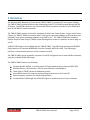
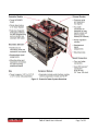
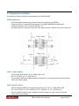
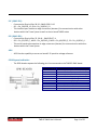
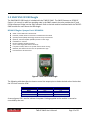
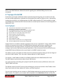
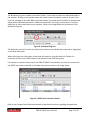
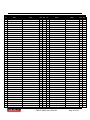
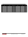
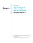
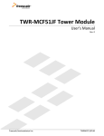
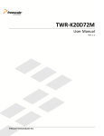
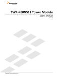
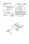
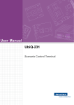
USER’S MANUAL
TWR-RF-SNAP
Document Revision v1.0
© 2011 Synapse, All Rights Reserved
All Synapse products are patented or patent pending
Specifications are subject to change without notice – confirm that data is current
Synapse, the Synapse logo, SNAP, and Portal are all registered trademarks of
Synapse Wireless, Inc.
500 Discovery Drive
Huntsville, Alabama 35806
877-982-7888
Doc # 600049-01A
© Freescale Semiconductor, Inc. 2011. All rights reserved.
Freescale™ and the Freescale logo are trademarks of
Freescale Semiconductor, Inc. All other product or service names
are the property of their respective owners.
TWR-RF-SNAP featuing the Synapse Wireless SM700 IEEE 802.15.4 RF Engine
Contents
1 Overview ......................................................................................................................................................3
2 Reference Documents ..............................................................................................................................5
3 Hardware Features ...................................................................................................................................6
3.1 Using the TWR-RF-SNAP ................................................................................................................................................. 6
Options for Powering the TWR-RF-SNAP Module:
Installing into the Tower System:
3.2 IEEE 802.15.4 RF Engine ................................................................................................................................................. 8
SM700 RF Engine: Synapse Part # SM700PC1
3.3 On-board Sensors, Inputs, and Indicators ................................................................................................................ 9
Temperature Sensor:
Photocell (Light Sensor):
Power Switch:
User LED 1 (Red):
User LED2 (Green):
Power LED:
Switch 2 (software accessible input):
Switch 3 (software accessible input):
Reset Button:
3.4 Expansion Interfaces ...................................................................................................................................................... 10
TWPRI Connector:
UART1 (SNAP UART0):
UART2 (SNAP UART1):
I2C (SNAP I2C):
SPI (SNAP SPI):
ADC:
GPIO Expansion Header:
3.5 SNAP SN132 USB Dongle.............................................................................................................................................. 12
RF100 RF Engine: Synapse Part # RF100P86
Software Features...................................................................................................................................... 13
3.6 SNAP / SNAPpy................................................................................................................................................................. 13
SNAP Highlights:
3.7 Synapse Portal IDE .......................................................................................................................................................... 14
Portal Highlights
4 Configuration Settings .......................................................................................................................... 18
4.1 Jumper / Switch Settings .............................................................................................................................................. 18
5 Electromechanicals ............................................................................................................................... 19
5.1 Elevator Connections ..................................................................................................................................................... 19
5.2 Tower Form-Factor ........................................................................................................................................................ 22
TWR-RF-SNAP User’s Manual
Page 2 of 22
1 Overview
The Wireless Mesh Networking Tower Board (TWR-RF-SNAP) is a peripheral Tower System Module.
The TWR-RF-SNAP provides wireless mesh networking via the FCC Certified Synapse Wireless SM700
RF Engine. The SM700 is based on the Freescale MC13224 chip which combines a 32-bit ARM7 MCU
with an IEEE 802.15.4 radio transceiver.
The TWR-RF-SNAP module can function standalone or within the Tower System. As part of the Tower
System, the TWR-RF-SNAP can interface with Tower System controller modules via SPI and can access
available Tower System peripheral modules using UART or I2C. The TWR-RF-SNAP also includes a
General Purpose Tower Plug-in (TWRPI) socket allowing direct access to a selection of sensor plug-ins
via I2C.
A SN132 USB Dongle is also included with the TWR-RF-SNAP. The USB Dongle features the RF100 RF
Engine based on a Freescale MC9S08 MCU and the Freescale MC13191 radio. The USB dongle
provides a communication portal to a host computer via USB.
The TWR-RF-SNAP can be accessed in Synapse’s Portal IDE using either the on-board USB or wirelessly
using the included RF100 USB Dongle.
The TWR-RF-SNAP features the following:
Synapse Wireless SM700. A surface-mount RF Engine powered by the Freescale MC13224.
Onboard Sensors / Push Buttons / LEDs for user interaction and feedback
Tower Plug-in (TWRPI) socket for additional sensors
microUSB connector for powering and providing wired access to the Portal IDE
Optional battery connector for untethered operation.
Included SN132 USB Dongle with RF100 RF Engine for wireless access to a host computer
TWR-RF-SNAP User’s Manual
Page 3 of 22
A block diagram for the TWR-RF-SNAP is shown in the figure below.
GPIO Expansion
Header
TWRPI Socket
I2C, Analog, GPIO
UART
Analog
Photocell
Sensor
Analog
Temp.
Sensor
SM700
I2C
Synapse Wireless
802.15.4 RF Engine
SPI
LEDs
UART
Reset
USB
Interface
microUSB
Isolation Jumper Block
Primary Tower Elevator Connector
GPIO
Pushbuttons
Figure 1 - TWR-RF-SNAP Block Diagram
TWR-RF-SNAP User’s Manual
Page 4 of 22
An image of the TWR-RF-SNAP with callouts is shown in the figure below.
Figure 2 - TWR-RF-SNAP Image
2 Reference Documents
The documents listed below should be referenced for more information on the Freescale Tower
system and the TWR-RF-SNAP. Refer to http://freescale.com/tower for the latest revision of all
released Tower documentation.
TWR-RF-SNAP Schematics
TWR-RF-SNAP Quick Start Guide
TWR-RF-SNAP Lab Document
TWR-RF-SNAP User’s Manual
Page 5 of 22
3 Hardware Features
This section provides more details about the features and functionality of the TWR-RF-SNAP.
3.1 Using the TWR-RF-SNAP
Options for Powering the TWR-RF-SNAP Module:
The module can be powered using any of the following options:
1) USB connector (either via USB AC-power supply or USB port on a PC)
2) The Tower Elevator modules (relying on the 5V supply pins)
3) The battery connector
Power Switch Settings:
Power Switch
Position
Operation
Far Left
Draws power from the battery connector
Middle
OFF
Far Right
Draws power from USB Port or Primary
Elevator connector
Installing into the Tower System:
In additional to functioning standalone, the TWR-RF-SNAP is designed to be used in the Freescale
Tower System. When inserted into the Tower System a Tower MCU module can utilize the TWR-RFSNAP to relay information to additional SNAP nodes, including the provided SN132 USB Dongle. The
TWR-RF-SNAP can also access compatible peripheral modules directly using I2C and SPI.
To ensure proper functionality of the TWR-RF-SNAP within the Tower System the Primary Edge
connector (marked with the white stripe) must be inserted into the Primary Elevator.
The TWR-RF-SNAP is also compatible with the General Purpose Tower Plug-in modules (or TWRPIs). A
TWRPI module can be inserted directly into the available socket on the TWR-RF-SNAP. The TWRPI
socket on the TWR-RF-SNAP provides access to I2C, Analog, and GPIO’s.
TWR-RF-SNAP User’s Manual
Page 6 of 22
Figure 3 - Freescale Tower System Overview
TWR-RF-SNAP User’s Manual
Page 7 of 22
3.2 IEEE 802.15.4 RF Engine
The TWR-RF-SNAP features the Synapse Wireless SM700 IEEE 802.15.4 RF Engine. The SM700 RF
Engine is based on the Freescale MC13224V transceiver platform. The SM700 comes with SNAP®
preloaded and ready to perform out of the box. SNAP is Synapse’s award-winning, mesh network
operating system that provides wireless connectivity for Internet-to-machine and machine-to-machine
communications.
SM700 RF Engine: Synapse Part # SM700PC1
Powerful 32-bit TDMI ARM7 microprocessor
Large on-board memory resources
o Allows for over-the-air SNAPpy script and SNAP OS upgrades
Accurate 12-bit ADC for precision sensors
SNAP – Instant-ON mesh network operating system
Powerful, reliable wireless connection in 2.4GHz license-free band
o 2.4 GHz RF Frequency (2400 - 2483.5 MHz)
o 16 RF Channels
Up to 100mW output power
-96 dBm Rx sensitivity
+20dBm Tx output power
2.0 to 3.6 Volts Vcc
Small footprint: 1” x 1.4” (25.4mm x 36.5mm)
Low power consumption:
o Transmit mode……193mA
o Receive mode………30mA
o Hibernate mode……1.1μA
Integrated F-antenna
Over 1.5 miles range
Available AES 128-bit encryption
FCC, CE and IC certified
TWR-RF-SNAP User’s Manual
Page 8 of 22
3.3 On-board Sensors, Inputs, and Indicators
The following interfaces are implemented in the TWR-RF-SNAP to allow for user interaction.
Temperature Sensor:
- Connected to ADC Ch. 1 (physical pin 9 of the SM700) – SNAP GPIO 31
- Low-Power Linear Active Thermistor IC
- Analog output
Photocell (Light Sensor):
- Connected to ADC Ch. 0 (physical pin 8 of the SM700) – SNAP GPIO 30
- Analog output
Power Switch:
- Left position – Draws power from the battery connector
- Middle position – OFF
- Right position – Draws power from the tower elevator or USB port
User LED 1 (Red):
- Connected to TMR0 (physical pin 34 of the SM700) – SNAP GPIO 8
- Activated by setting the pin HIGH
User LED2 (Green):
- Connected to TMR1 (physical pin 33 of the SM700) – SNAP GPIO 9
- Activated by setting the pin HIGH
Power LED:
- Green LED (D5) will indicate when power is applied to the board
Switch 2 (software accessible input):
- Connected to Physical Pin 57 of the SM700 – SNAP GPIO 22
- KBI pin – wake from sleep interrupt capable
- Switch is grounded when pressed
Switch 3 (software accessible input):
- Connected to Physical Pin 56 of the SM700 – SNAP GPIO 23
- KBI pin – wake from sleep interrupt capable
- Switch is grounded when pressed
Reset Button:
- Push button tied directly to RESET on the SM700 / Reboots the device
TWR-RF-SNAP User’s Manual
Page 9 of 22
3.4 Expansion Interfaces
The following interfaces allow for expandability of the TWR-RF-SNAP.
TWPRI Connector:
- Freescale standard connector for General Purpose Tower Plug-ins (TWRPIs)
- Allows for plug-in of several different sensors – ex.TWRPI-MMA7660 Accelerometer
- Interfaces to sensors via I2C and/or ADC (ADC 5-7)
- See figure below for specific pin-out (J15 is the right connector, while J14 is the left connector)
UART1 (SNAP UART0):
- Connected to Physical Pins 36-37 – SNAP GPIO 14-15
- RX = Pin 37/GPIO_15, TX = 36/GPIO_14
- This serial port attaches to edge-connectors (elevator) for communication with other devices
within the Tower System
UART2 (SNAP UART1):
- USB connected to UART2 of the system (Physical Pins 21, 23-25) - SNAP GPIO 21-18
- RTS = Pin_21/GPIO_21, CTS= 23/GPIO_20, RX = 24/GPIO_19 , TX = 25/GPIO_18
- Used to upload firmware, factory default the SNAP settings, or erase a script (via Portal)
- Connected to the USB port
TWR-RF-SNAP User’s Manual
Page 10 of 22
I2C (SNAP I2C):
- Connected to Physical Pins 28-29 – SNAP GPIO 13-12
- SCL = Pin_29/GPIO_12, SDA = Pin_28/GPIO_13
- This interface port attaches to edge-connectors (elevator) for communication with other
devices within the Tower System as well as the on-board TWRPI socket
SPI (SNAP SPI):
- Connected to Physical Pins 35, 39-41 – SNAP GPIO 7-4
- SCK = Pin_35/GPIO_7, MOSI = Pin_39/GPIO_6, MISO = Pin_40/GPIO_5, SS = Pin_41/GPIO_4
- This serial interface bus attaches to edge-connectors (elevator) for communication with other
devices within the Tower System
ADC:
- ADC1 has the capability to use an on-board 2.5V precision voltage reference
GPIO Expansion Header:
- The GPIO header exposes the following pins for use external to the TWR-RF-SNAP board:
GPIO Header (J6)
1
2
3
4
5
6
7
8
9
10
Pin Description
SNAP GPIO_28 / Keyboard Interrupt 6 (KBI_6)
Vcc (3.3V)
SNAP GPIO_29 / Keyboard Interrupt 7 (KBI_7)
SNAP GPIO_0 / SSI_TX
SNAP GPIO_1 / SSI_RX
SNAP GPIO_2 / SSI_FSYN
SNAP GPIO_3 / SSI_BITCK
SNAP GPIO_21 / UART1_RTS (SNAP SW UART0)
GND
SNAP GPIO_20 / UART1_CTS (SNAP SW UART0)
TWR-RF-SNAP User’s Manual
Page 11 of 22
3.5 SNAP SN132 USB Dongle
The SNAP SN132 USB Dongle is included with the TWR-RF-SNAP. The SN132 features an RF100 RF
Engine. It is not only its own free-standing node in the SNAP network, but also provides the PC and
Portal software a bridge into the SNAP network. Refer to the lab material associated with the TWR-RFSNAP module for more about the USB dongle.
RF100 RF Engine: Synapse Part # RF100P86
SNAP – Instant-ON mesh network stack
Powerful, reliable wireless connection in 2.4GHz license-free band
Spread spectrum (DSSS) technology surmounts noisy environments
Optional, Transmit amplifier (18 dBm) for best-in-class range
Embedded “F” antenna
Receive amplifier (10 dBm) standard
Up to 3-mile range (with external antenna)
Low power modes, down to 2.5 μA with internal timer running
60k flash, with 20k free for over-the-air uploaded user apps
FCC Certified on all 16 channels
Figure 4 - SNAP SN132 USB Dongle
The following table describes the how to control the output pins to obtain desired colors. Notice that
the LED lines are active LOW.
Desired LED Color
Red
Green
Amber
OFF
Value of GPIO Pin 0
Low
High
Low
High
Value of GPIO Pin 1
High
Low
Low
High
A second green LED is used to indicate that power is being supplied to the module. It cannot be
controlled by the user.
TWR-RF-SNAP User’s Manual
Page 12 of 22
Software Features
This section provides more details about the software features and functionality of the TWR-RF-SNAP
including the Synapse Wireless Portal IDE and python based SNAPpy scripts.
3.6 SNAP / SNAPpy
Synapse's SNAP® technology is an Internet-enabled, auto-forming, multi-hop, mesh network Operating
System that is designed to run efficiently on all types of microcontroller; including cost-effective 8-bit
microprocessors.
With the SNAP protocol firmware installed, the device automatically forms an ad-hoc radio mesh
network with other SNAP devices in range, so each can pass information back and forth, and can relay
messages to other SNAP devices that might be out of the original sender’s range.
Since SNAP provides a full mesh network, there is no single point of failure: any node can talk directly
to any other node that is in range and any node can talk indirectly to any other node via intermediate
nodes. SNAP-based networks are self-forming, instant-on, and self-healing.
The SNAP core code handles wireless communications, as well as implementing a Python virtual
machine. The subset of Python implemented by the core software is named SNAPpy. Scripts written in
SNAPpy (also referred to as Device Images, SNAPpy images or even Snappy Images) can be uploaded
into SNAP Nodes serially (or even over the air), and dramatically alter the nodes capabilities and
behavior.
The TWR-RF-SNAP comes preloaded with the SNAP firmware, including an initial SNAPpy script that
allows the user to interact with the LEDs by pressing the on-board push-buttons. For more
information regarding this example SNAPpy script, refer to the TWR-RF-SNAP lab guide.
SNAP Highlights:
Multi-hop mesh
Auto-forming
Instant-on
Peer-to-peer
SNAPpy application scripts (Python-based programming language)
Over-the-air programming
Remote Procedure call architecture
Processor independence
Sleepy Mesh – allows for battery operation
Each node runs autonomously
No central coordinator since each node can participate in routing
No single point of failure
TWR-RF-SNAP User’s Manual
Page 13 of 22
Refer to the SNAP Reference Manual for details regarding the available SNAPpy functions and
commands.
3.7 Synapse Portal IDE
Portal takes you beyond traditional network commissioning tools by giving you an end-to-end view
into your wireless application. Implement the functionality you need one step at a time - dynamically,
interactively, wirelessly. As a bridge between the SNAP network and the PC, Portal provides a simple
and flexible Python-based interface. Remote nodes can invoke Python functions in Portal using built-in
SNAPpy RPC calls.
Portal Highlights
Comprehensive administration tool for SNAP networks
Participates as a full peer on the network
Syntax-highlighted Python editor for developing SNAPpy scripts
Invoke (RPC) script functions on any device in network
Remote nodes can invoke (RPC) scripts within Portal
Channel analyzer to find ideal channel
Event Log with timestamps and filtering
Graphical Data Logger
Node configuration editor
Channel scanner to detect new or un-configured nodes
Connect to SNAP Connect over Internet or TCP/IP LAN
Synapse Portal is a standalone software application that runs on a standard PC. Using a USB or RS232
interface, it connects to any node in the SNAP Wireless Network and becomes a graphical user
interface (GUI) for the entire network. Using Portal, you can quickly and easily create, deploy,
configure, and monitor SNAP-based network applications. Once connected, the Portal PC has its own
unique SNAP Network Address and can participate in the SNAP network as a peer.
The address of each node within the SNAP network can be determined by looking at the last 6 digits of
the device’s MAC address. This is the node’s unique address in a SNAP network.
For example: a MAC address of 00:1C:2C:1E:86:03:A2:A6 will use the SNAP address 03.A2.A6.
The MAC address is printed on the label of each SNAP device.
For a quick overview of installing the Synapse Portal IDE and the necessary USB drivers refer to the
TWR-RF-SNAP Lab Guide.
The Default View of Portal IDE consists of the following key panels and tool bars: Main Toolbar, Node
View Panel, Node Info Panel, Node Info Toolbar, and Event Log Panel.
From this user interface you can connect to a SNAP bridge node and start viewing and configuring your
SNAP network. The nodes in your network will be displayed in the Node Views window as they start
TWR-RF-SNAP User’s Manual
Page 14 of 22
responding to queries made by Portal. Selecting a node by clicking on it in the Node Views window will
display detailed information about that node over in the Node Info window. Finally, the Event Log
window displays event message about things that have occurred in the system and in the SNAP
network. The Main Toolbar will provide icons to open existing scripts, create new scripts, connect to a
Port Node, and perform a broadcast ping of the network. The Node Info Toolbar
Main
Toolbar
Node Info
Toolbar
Node Info
Node View
Event Log
Figure 5 - Portal IDE Application
With the SN132 USB Dongle connected to the PC running the Portal IDE and the TWR-RF-SNAP
powered externally and within range of the SN132, the application will identify the USB Dongle as an
available SNAP Bridge Device on Port USB0.
TWR-RF-SNAP User’s Manual
Page 15 of 22
Figure 6 - SNAP Bridge Device Connect
The application will then attempt to identify all available Nodes available in the network as seen in the
figure below. The TWR-RF-SNAP will be identified as a SNAPTower Node (Device Type: TWR_SNAP).
Figure 7 - SNAPTower in Portal
TWR-RF-SNAP User’s Manual
Page 16 of 22
The Broadcast Ping icon, located in the Main Toolbar, can be used to refresh the identified Nodes in
the network. Clicking on this toolbar button will cause Portal to broadcast a special “answer if you
hear me” message to all nodes. When the nodes answer, any nodes that Portal did not already know
about will be individually queried for additional information. You might use this button if you just
added one or more new nodes to your network. Refer to the image below for the location of the
Broadcast Ping icon.
Figure 8 - Broadcast Ping Icon
The Node Info panel will contain only information relevant to the Node that is selected or highlighted
in the Node View panel.
When referring to the information in the Node Info panel or using the Node Info Toolbar it is
important that the correct SNAP Node is first selected in the Node View panel.
For example, to upload a new script to the TWR-RF-SNAP Tower Module, you must first ensure that
the SNAPTower Node is selected in the Node Info panel as shown in the image below.
Figure 9 - SNAPTower Selected in Portal
Refer to the Synapse Portal Reference Manual for detailed instructions regarding the application.
TWR-RF-SNAP User’s Manual
Page 17 of 22
4 Configuration Settings
4.1 Jumper / Switch Settings
There are several jumpers provided for isolation, configuration, and feature selection. Refer to the
following table for details.
Jumper Options
J5
TWR-ELEV
Connection
Jumper
Setting
1-2
3-4
5-6
7-8
9-10
11-12
13-14
15-16
17-18
19-20
Left
Center
Right
Switch 1
3-Position
Power Switch
Switch 2
Push Button
Pressed
Switch 3
Push Button
Pressed
Switch 4
Push Button
Pressed
Description
I2C SCL - Connects I2C_SCL to TWR-ELEV
(ELEV_SCL0)
I2C SDA - Connects I2C_SDA to TWR-ELEV
(ELEV_SDA0)
UART RX - Connects UART1_TXD to TWR-ELEV (ELEV_RXD0)
UART TX - Connects UART1_RXD to TWR-ELEV (ELEV_TXD0)
SPI MISO - Connects SPI_MISO to TWR-ELEV
(ELEV_SPI0_MISO)
SPI MOSI - Connects SPI_MOSI to TWR-ELEV
(ELEV_SPI0_MOSI)
SPI CS
- Connects SPI_SS to TWR-ELEV
(ELEV_SPI0_CS0)
SPI CS
- Connects SPI_SS to TWR-ELEV
(ELEV_SPI0_CS1)
SPI CLK - Connects SPI_SCLK to TWR-ELEV
(ELEV_SPI0_CLK)
RESET
- Connects RESET to TWR-ELEV
(ELEV_RSTOUT_B)
Powered via Battery Terminal: Switched towards battery connection
OFF
Powered via USB / Tower System : Switched towards USB receptacle
Switch connects SM700 GPIO 22 to GND when pressed. Pin can be used as
an interrupt pin to wake the SM700 from sleep.
Switch connects SM700 GPIO 23 to GND when pressed. Pin can be used as
an interrupt pin to wake the SM700 from sleep.
Resets the SM700
TWR-RF-SNAP User’s Manual
Page 18 of 22
5 Electromechanicals
5.1 Elevator Connections
The TWR-RF-SNAP features two expansion card-edge connectors that interface to Elevator boards in a
Tower System: the Primary and Secondary Elevator connectors. Table 1 provides the pinout for the
Primary and Secondary Elevator Connector. An “X” in the “Used” column indicated that there is a
connection from the TWR-MEM to that pin on the Elevator connector. An “X” in the “Jmp” column
indicates that a jumper is available that can configure or isolate the connection from the Elevator
connector.
Table 1 - TWR-RF-SNAP Primary Elevator Connector Pinout
TWR-RF_SNAP Primary Connector
Pin
Name
Usage
Used Jmp
Pin
Name
Usage
Used
Jmp
B1
5V
5.0V Power
X
A1
5V
5.0V Power
X
B2
GND
Ground
X
A2
GND
Ground
X
B3
3.3V
3.3V Power
A3
3.3V
3.3V Power
B4
ELE_PS_SENSE
Elevator Power Sense
A4
3.3V
3.3V Power
B5
GND
Ground
X
A5
GND
Ground
X
B6
Ground
X
A6
B7
GND
SDHC_CLK / SPI1_CLK
A7
GND
SCL0
Ground
ELEV_SCL0 (ISC_SCL)
X
X
X
B8
SDHC_D3 / SPI1_CS1_b
A8
SDA0
ELEV_SDA0 (I2C_SDA)
X
X
Ground
X
B9
SDHC_D3 / SPI1_CS0_b
A9
GPIO9 / CTS1
B10
SDHC_CMD / SPI1_MOSI
A10
GPIO8 / SDHC_D2
B11
SDHC_D0 / SPI1_MISO
A11
GPIO7 / SD_WP_DET
B12
ETH_COL
A12
ETH_CRS
B13
ETH_RXER
A13
ETH_MDC
B14
ETH_TXCLK
A14
ETH_MDIO
B15
ETH_TXEN
A15
ETH_RXCLK
B16
ETH_TXER
A16
ETH_RXDV
B17
ETH_TXD3
A17
ETH_RXD3
B18
ETH_TXD2
A18
ETH_RXD2
B19
ETH_TXD1
A19
ETH_RXD1
B20
ETH_TXD0
A20
ETH_RXD0
B21
GPIO1 / RTS1
A21
SSI_MCLK
B22
GPIO2 / SDHC_D1
A22
SSI_BCLK
B23
GPIO3
A23
SSI_FS
B24
CLKIN0
A24
SSI_RXD
B25
CLKOUT1
A25
SSI_TXD
B26
GND
AN7
A26
B27
A27
GND
AN3
B28
AN6
A28
AN2
Ground
X
TWR-RF-SNAP User’s Manual
Page 19 of 22
TWR-RF_SNAP Primary Connector
Pin
B29
Name
AN5
Usage
Used Jmp
Pin
B30
AN4
B31
B32
GND
DAC1
B33
TMR3
B34
TMR2
A34
TMR0
B35
GPIO4
A35
GPIO6
B36
3.3V
PWM7
A36
B37
A37
3.3V
PWM3
B38
PWM6
A38
PWM2
B39
PWM5
A39
PWM1
B40
PWM4
A40
PWM0
B41
CANRX0
A41
RXD0
ELEV_RXD0 (UART1_TXD)
X
X
B42
CANTX0
A42
TXD0
ELEV_TXD0 (UART1_RXD)
X
X
B43
1WIRE
A43
RXD1
B44
SPI0_MISO (IO1)
ELEV_SPI0_MISO (SPI_MISO)
X
X
A44
TXD1
B45
SPI0_MOSI (IO0)
ELEV_SPI0_MOSI (SPI_MOSI)
X
X
A45
VSS
B46
SPI0_CS0_b
ELEV_SPI0_CS0 (SPI_SS)
X
X
A46
VDDA
B47
SPI0_CS1_b
ELEV_SPI0_CS1 (SPI_SS)
X
X
A47
VREFA1
B48
SPI0_CLK
ELEV_SPI0_CLK (SPI_SCLK)
X
X
A48
VREFA2
B49
GND
SCL1
Ground
X
Ground
X
B50
B51
ELEV_RSTOUT_B (RESET)
X
Ground
X
A29
Ground
X
3.3V Power
Name
AN1
A30
AN0
A31
A32
GND
DAC0
A33
TMR1
A49
GND
A50
GPIO14
SDA1
A51
GPIO15
B52
GPIO5 / SPI0_HOLD (IO3)
A52
GPIO16 / SPI0_WP (IO2)
B53
USB0_DP_PDOWN
A53
B54
A54
GPIO17
USB0_DM
B55
USB0_DM_PDOWN
IRQ_H
A55
USB0_DP
B56
IRQ_G
A56
USB0_ID
B57
IRQ_F
A57
USB0_VBUS
B58
IRQ_E
A58
TMR7
B59
IRQ_D
A59
TMR6
B60
IRQ_C
A60
TMR5
B61
IRQ_B
A61
TMR4
B62
IRQ_A
A62
RSTIN_b
B63
EBI_ALE / EBI_CS1_b
A63
RSTOUT_b
B64
EBI_CS0_b
A64
CLKOUT0
B65
GND
A65
GND
B66
EBI_AD15
A66
EBI_AD14
B67
EBI_AD16
A67
EBI_AD13
B68
EBI_AD17
A68
EBI_AD12
B69
EBI_AD18
EBI_AD19
A69
EBI_AD11
B70
A70
EBI_AD10
B71
EBI_R/W_b
A71
EBI_AD9
B72
EBI_OE_b
A72
EBI_AD8
Ground
X
TWR-RF-SNAP User’s Manual
Usage
Ground
Used
Jmp
X
3.3V Power
Page 20 of 22
X
TWR-RF_SNAP Primary Connector
Pin
B73
Name
EBI_D7
Usage
Used Jmp
A73
EBI_AD7
B74
EBI_D6
A74
EBI_AD6
B75
EBI_D5
A75
EBI_AD5
B76
EBI_D4
A76
EBI_AD4
B77
EBI_D3
A77
EBI_AD3
B78
EBI_D2
A78
EBI_AD2
B79
EBI_D1
A79
EBI_AD1
B80
EBI_D0
A80
EBI_AD0
B81
GND
Ground
A81
GND
Ground
B82
3.3V
3.3V Power
A82
3.3V
3.3V Power
X
Pin
Name
TWR-RF-SNAP User’s Manual
Usage
Used
X
Page 21 of 22
Jmp
5.2 Tower Form-Factor
The TWR-RF-SNAP is designed for the Freescale Tower System as a side mounting peripheral and
complies with the electrical and mechanical specification as described in Freescale Tower
Electromechanical Specification.
Figure 10 - Tower Board size
TWR-RF-SNAP User’s Manual
Page 22 of 22