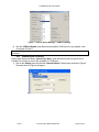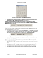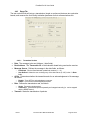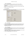
1
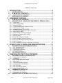
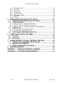
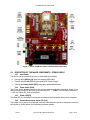
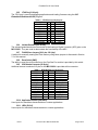
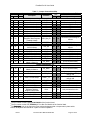
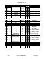
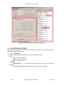
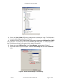
Free Star Pro Series ZFSM-201-KIT-1 Development Kit User's Guide ZFSM-201-1 FreeStar Pro Module Document # 0006-00-08-00-000 (Rev B) FreeStar Pro Kit User Guide Table of Contents 1 INTRODUCTION .............................................................................. 4 1.1 1.2 KIT DESCRIPTION ...................................................................................... 4 ZFSM-201-KIT-1 CONTENTS...................................................................... 5 1.2.1 Optional Hardware and Software ........................................................................ 5 1.3 REFERENCED DOCUMENTS .................................................................... 6 2 HARDWARE OVERVIEW ................................................................ 6 2.1 2.2 ZFSM-201-EVB-1 OVERVIEW .................................................................... 6 DESCRIPTION OF THE MAJOR COMPONENTS – ZFSM-201-EVB-1....... 7 2.2.1 Input Power: ........................................................................................................ 7 2.2.2 Power Switch [SW6]: ........................................................................................... 7 2.2.3 Power LED [D5]................................................................................................... 7 2.2.4 Current Measurement Jumper [J9 2-pin] ............................................................. 7 2.2.5 JTAG Port [J1 20-pin]: ......................................................................................... 8 2.2.6 Variable Resistors [VR1 & VR2]: ......................................................................... 8 2.2.7 FLASH Erase Jumpers [J19 2-pin, J20 2-pin]: .................................................... 8 2.2.8 Reset Switch [SW5]:............................................................................................ 8 2.2.9 GPIO Header Connector [J2 26-pin] ................................................................... 8 2.2.10 Application Switches [SW1-SW4] ........................................................................ 8 2.2.11 LED’s [D1-D4] ..................................................................................................... 8 2.2.12 Timer I/O Connector [J3 4-pin] ............................................................................ 9 2.2.13 Supply Voltage Connector [J4 4-pin] ................................................................... 9 2.2.14 ADC Input Channel Connector [J5 8-pin] ............................................................ 9 2.2.15 Add on Antenna ................................................................................................... 9 2.2.16 GPIO Jumpers [J13 40-pin, J14 40-pin, J15 40-pin]: .......................................... 9 3 ZFSM-201-EVB-1 STANDALONE DEMONSTRATIONS ............... 12 3.1 TRANSMISSION/RANGE DEMONSTRATION ......................................... 12 3.1.1 The Transmitter Setup ....................................................................................... 12 3.1.2 The Receiver Setup........................................................................................... 12 3.1.3 Transmission Indicators ..................................................................................... 12 3.1.4 Testing the Range ............................................................................................. 12 3.2 ADC DEMONSTRATION ........................................................................... 12 4 FREESTAR PRO TEST TOOL SOFTWARE .................................. 13 4.1 SOFTWARE INSTALLATION AND SETUP ............................................... 13 4.1.1 Prerequisites to Installation ............................................................................... 13 4.1.2 Installation ......................................................................................................... 13 4.2 GUI SCREEN DESCRIPTIONS ................................................................. 14 4.2.1 Menu Items........................................................................................................ 14 4.2.2 Transceiver Settings Window: ........................................................................... 15 4.2.3 Communications Log Window: .......................................................................... 15 4.2.4 Test Tool Tabs: .................................................................................................. 15 4.2.5 Test Tool Settings Window: ............................................................................... 15 4.2.6 Comm Status Window: ...................................................................................... 16 4.3 COMMUNICATIONS SETUP ..................................................................... 16 4.3.1 Virtual Serial Port Setup .................................................................................... 16 4.3.2 Establishing the Connection .............................................................................. 18 4.4 DESCRIPTIONS OF THE MAC TEST TOOLS .......................................... 20 Rev B Document No. 0006-00-08-00-000 Page 2 of 42 FreeStar Pro Kit User Guide 4.4.1 4.4.2 4.4.3 4.4.4 4.4.5 4.4.6 4.4.7 4.4.8 RF Evaluation Tab ............................................................................................. 20 PERT Tab .......................................................................................................... 20 Range Tab ......................................................................................................... 22 Settings Tab....................................................................................................... 23 Low Power Tab .................................................................................................. 24 Transceiver Info Tab .......................................................................................... 25 GPIO Tab........................................................................................................... 26 ED Tab............................................................................................................... 27 5 DEMONSTRATION USING TEST TOOLS ..................................... 27 5.1 5.2 PREREQUISITE HARDWARE AND SOFTWARE ..................................... 27 SETUP METHODS .................................................................................... 27 5.2.1 Mode A: One PC, Two Boards Connected ....................................................... 28 5.2.2 Mode B: Two PC’s, Two Boards Connected ..................................................... 28 5.2.3 Mode C: One PC, One Board Connected – One Standalone .......................... 28 5.3 RANGE TEST ............................................................................................ 29 5.3.1 The Transmitter Connected to the PC ............................................................... 29 5.3.2 The Receiver Connected to the PC ................................................................... 31 5.4 PERT TAB (PACKET ERROR RATE TEST) .............................................. 32 6 USING THE GUI WITH THE SMAC ............................................... 34 6.1 6.2 6.3 RF POWER .................................................................................................. 34 RANGE TEST................................................................................................ 35 ENERGY SCAN ............................................................................................. 35 7 DOWNLOADING TO FLASH THROUGH THE USB ..................... 36 7.1 7.2 7.3 PREREQUISITE HARDWARE AND SOFTWARE ..................................... 36 ERASING FLASH MEMORY ..................................................................... 36 DOWNLOADING NEW FLASH IMAGE ..................................................... 36 8 REVISION HISTORY ...................................................................... 40 APPENDIX 1: USING AN EXTERNAL ANTENNA ............................. 41 APPENDIX 2: LICENSING ARRANGEMENTS .................................. 42 Rev B Document No. 0006-00-08-00-000 Page 3 of 42 FreeStar Pro Kit User Guide 1 INTRODUCTION This document is the user guide for the California Eastern Laboratories (CEL) FreeStar Pro Evaluation Kit, (ZFSM-201-KIT-1). The kit is a collection of hardware and software assembled to allow a customer to design a remote sensing, AMR/AMI, home and building automation, industrial control, or security application. 1.1 KIT DESCRIPTION The main component in the Evaluation Kit is the ZFSM201-EVB-1 FreeStar Pro Evaluation Board. The board serves as an interface, evaluation and development tool enabling the user to demonstrate, and evaluate the capabilities of the CEL ZFSM-201-1, FreeStar Pro Module. At the heart of the CEL ZFSM-201-1 is the Freescale MC13224V Platform-in-Package (PiP) transceiver, a 32-bit ARM-based ZigBee radio module and a third-generation 2.4GHz IEEE® 802.15.4 platform. The 32-bit ARM7 processor and extensive on-chip memory allows designers to eliminate the peripheral host processors often required by 8- and/or 16-bit transceiver solutions. The high level of integration also helps to reduce component count, lowering power consumption and reducing overall system cost. The evaluation kit provides the end user the ability to quickly become familiar with both the ZFSM-201-1 FreeStar Pro module’s hardware and software. Each evaluation board comes preloaded with firmware demonstrating a wireless link and communicating with the supplied FreeStar Pro Test Tool Graphical User Interface (GUI). Full application source code of the firmware is based on Freescale’s SMAC and MAC Rev B Document No. 0006-00-08-00-000 Page 4 of 42 FreeStar Pro Kit User Guide codebases for ARM7® are supplied in an IAR Embedded Workbench for ARM project. The source code exercises key features of the MC13224V and provides a good reference or starting point for creating custom applications on the SMAC codebase. NOTE: The MACPHY.A library file has been removed from the pre-programmed Freescale MAC example project. The user will need to install the Freescale BeeKit™ and agree to the Terms and Conditions to receive the MACPHY.A library file. Both applications include the following features: RF Evaluation Range Test Application Packet Error Rate Test (PERT) Application Transmitting and receiving on the UART Using low power modes Reading and writing to Non-Volatile Memory (NVM) Reading Analog to Digital Converters Using GPIOs 1.2 ZFSM-201-KIT-1 CONTENTS Qty 3 2 4 10 1 Part Number ZFSM-201-EVB-1 94611-6 2.0 ver. A-B M/M 6' Any 3M 929955-06 (0.1" SHUNT JUMPER) CEL #0006-03-00-00-000 Description FreeStar Pro Evaluation Boards (with firmware loaded) USB interface cables Type AA Batteries Shorting Jumpers CEL Informational CD The CEL Informational CD contains: CEL Documentation (See list in Section 1.3) Set-up files for the FreeStar Pro Test Tool program Sample Project files o o o A Project File for IAR Workbench® A Solution File for BeeKit™ Application Firmware files for the ZFSM-201-1 Module Files for loading theFreescale BeeKit™ and Test Tool 1.2.1 Optional Hardware and Software Manufacturer/Part Number Description Hardware Components Manufacturer: Phihong P/N: PSA05R-090-R Manufacturer: IAR Systems P/N: JLINK ARM 9V DC 0.5A Power Supply IAR J-Link for ARM Debug Probe (recommended for development) Software Components Manufacturer: IAR Systems Name: EWARM Manufacturer: Freescale Name: BeeKit Rev B IAR Embedded Workbench® IDE – Development and Compiler software (required for development) BeeKit™ – Freescale Wireless Connectivity Toolkit Document No. 0006-00-08-00-000 Page 5 of 42 FreeStar Pro Kit User Guide 1.3 REFERENCED DOCUMENTS Table 1 contains the documents that have been referenced by this document (or recommended as additional information). Please consult the appropriate website to check for the latest revisions and editions. Table 1 – Related and Referenced Documents Document Title Document Name / Number Freescale Semiconductor Documents (www.freescale.com) BeeKit™ Wireless Connectivity Toolkit Quick Start Guide BKWCTKQSG BeeKit™ Wireless Connectivity Toolkit User’s Guide BKWCTKUG BeeKit™ Wireless Connectivity Toolkit Software Release Notes BKWCTKRN MC13224V Datasheet MC1322x MC1322x Reference Manual MC1322xRM MC1322x Software Driver Reference Manual 22XDRVRRM MC1322x Simple Media Access Controller (SMAC) Reference Manual 22xSMACRM 802.15.4 Media Access Controller (MAC) MyWirelessApp 802154MWAUG 802.15.4 Media Access Controller (MAC MyStarNetworkApp 802154MSNAUG 802.15.4 MAC PHY Software Reference Manual 802154MPSRM Simple Media Access Controller (SMAC) User’s Guide SMACRM Freescale Test Tool User’s Guide TTUG Note: The Freescale documents listed above will be loaded to the user’s PC when installing the BeeKit™ Toolkit found on the CEL Freestar Pro CD CEL Documents (www.cel.com) ZFSM-201-1 Datasheet 0006-00-07-00-000 ZFSM-201-KIT-1 Development Kit User Guide 0006-00-08-00-000 ZFSM-201-EVB-1 Evaluation Board Host Serial & RF Protocol Guide 0006-00-08-01-000 ZFSM-201-EVB-1 Evaluation Board SMAC Programmers Guide 0006-00-08-02-000 ZFSM-201-EVB-1 Evaluation Board BeeKit™ Porting Guide 0006-00-08-03-000 ZFSM-201-EVB-1 Evaluation Board MAC Programmers Guide 0006-00-08-05-000 ZFSM-201-KIT-1 Wireless UART Application User Guide 0006-00-08-06-000 ZFSM-201-KIT-1, ZFSM-201-EVB-1 Erratum 0006-00-08-04-000 Note: The CEL documents listed above are included on the CEL CD. 2 2.1 HARDWARE OVERVIEW ZFSM-201-EVB-1 OVERVIEW The ZFSM-201-1 FreeStar Pro module is a 2.4GHz IEEE 802.15.4 compliant data transceiver module (based on the Freescale MC13224V) with a 100mW power amplifier providing enhanced range performance. Two crystals needed for the clock oscillators are also incorporated into the module. The module also contains an integrated PCB trace antenna and possesses the ability to optionally add an MMCX connector in order to use an external antenna. The procedure for adding the connector is located in APPENDIX 1: USING AN EXTERNAL ANTENNA at the end of this document. In order to interface with the module, it has been mounted to a PCB to produce a ZFSM-201EVB-1 Evaluation Board as pictured in Figure 1. Rev B Document No. 0006-00-08-00-000 Page 6 of 42 FreeStar Pro Kit User Guide Figure 1 – Photo, ZFSM-201-EVB-1 Evaluation Board (top view) 2.2 DESCRIPTION OF THE MAJOR COMPONENTS – ZFSM-201-EVB-1 2.2.1 Input Power: The device can be powered using any of three different methods: Through the USB Port [J6] using the supplied USB cable Through the DC Jack [J7] using an optional DC Power Supply Through the Battery Holder [BC2] using two supplied AA batteries 2.2.2 Power Switch [SW6]: The Power Switch applies power from the chosen power source to the evaluation board. It is a three position switch with the three positions being OFF → ‘V BAT’ (ON for battery operation) → ON (for USB or DC Jack connections) 2.2.3 Power LED [D5] This Red LED is connected to input power bus and will be illuminated when power is applied. 2.2.4 Current Measurement Jumper [J9 2-pin] The jumper on J9 can be removed and a current meter placed in series to measure current into the module, a useful feature for evaluating low-power modes. Rev B Document No. 0006-00-08-00-000 Page 7 of 42 FreeStar Pro Kit User Guide 2.2.5 JTAG Port [J1 20-pin]: The JTAG port is used for debugging applications and loading firmware using the IAR Embedded Workbench® IDE program. Table 2 – JTAG Port Connector pins Description Pin Pin Description VCC 1 2 VCC 3 4 GND not connected TDI 5 6 GND TMS 7 8 GND TCK 9 10 GND RTCK 11 12 GND TDO 13 14 GND DBGRQ 15 16 GND DBGACK 17 18 GND 19 20 GND not connected 2.2.6 Variable Resistors [VR1 & VR2]: The onboard potentiometers are connected to the Analog to Digital Converter (ADC) pins on the MC13224V. They are used to demonstrate the functionality of the ADC. 2.2.7 FLASH Erase Jumpers [J19 2-pin, J20 2-pin]: A method for manually erasing the Flash memory using these jumpers is discussed in Section 7.2 of this manual. 2.2.8 Reset Switch [SW5]: The ability to reset the microcontroller on the FreeStar Pro module is provided by this switch. 2.2.9 GPIO Header Connector [J2 26-pin] Additional access to selected I/O pins on the MC13224V is provided at this connector. Table 3 – GPIO Header Connector pins I/O Pin Pin I/O TMR1 1 2 not connected VCC 3 4 GND ADC1 5 6 ADC2 ADC3 7 8 ADC4 ADC5 9 10 not connected SSI_TX 11 12 SSI_RX (GPIO1) SSI_FSYN 13 14 SSI_BITCK KBI0 (GPIO22) 15 16 KBI4 (GPIO26) UART2_TX 17 18 UART2_RX UART2_RTS 19 20 UART2_CTS I2C_SCL 21 22 I2C_SDA SPI_SCK 23 24 SPI_SS SPI_MOSI 25 26 SPI_MISO 2.2.10 Application Switches [SW1-SW4] User inputs for standalone demonstrations or custom applications. 2.2.11 LED’s [D1-D4] User outputs for standalone demonstrations or custom applications. Rev B Document No. 0006-00-08-00-000 Page 8 of 42 FreeStar Pro Kit User Guide 2.2.12 Timer I/O Connector [J3 4-pin] The four Timer I/O signals are available on the J3 connector. Table 4 – Timer I/O Connector pins Pin 1 Pin 2 Pin 3 Pin 4 TMR0 TMR1 TMR2 TMR3 2.2.13 Supply Voltage Connector [J4 4-pin] This connector allows powering of the EVB directly (bypassing the regulator) through Pin 3 and allows monitoring of the module’s VCC through Pin 4 (SENSE+) Table 5 – VCC Connector pins Pin 1 Pin 2 Pin 3 Pin 4 GND VCC VCC Module GND (SENSE–) In (SENSE+) 2.2.14 ADC Input Channel Connector [J5 8-pin] The eight ADC input channels are available on the J5 connector. Pin 1 ADC0 Table 6 – ADC Input Channel Connector pins Pin 2 Pin 3 Pin 4 Pin 5 Pin 6 Pin 7 ADC1 ADC2 ADC3 ADC4 ADC5 ADC6 Pin 8 ADC7 2.2.15 Add on Antenna The module contains an integrated PCB antenna and possesses the capacity to add an external antenna to the module. A simple procedure for making this change (adding the connector, changing the position of a capacitor) is included in APPENDIX 1: USING AN EXTERNAL ANTENNA located at the end of this document. 2.2.16 GPIO Jumpers [J13 40-pin, J14 40-pin, J15 40-pin]: Three 40-pin jumper connectors provide access to the I/O pins of the ZFSM-201-1 FreeStar Pro module and as a result to most of the I/O pins of the Freescale MC13224V device. Table 7 below shows the connections made by each jumper for each of the three connectors J13, J14 and J15 as shown in Figure 2. Figure 2 – Pin numbering for the 40-pin Jumper Connectors (J13, J14 and J15) Rev B Document No. 0006-00-08-00-000 Page 9 of 42 FreeStar Pro Kit User Guide Pin # Table 7 – Jumper Connections Map Connection to the Module/IC Connector Pins GPIO Description Pin Name # # # IC1 Mod2 86 79 42 41 40 39 38 37 78 59 58 57 56 55 54 53 52 51 22 23 24 25 26 27 - 44 50 - 51 36 49 48 28 43 47 - 35 34 33 32 31 30 46 45 44 43 42 41 29 0 1 2 3 4 29 40 5 Connection on the EVB designates Jumper3 Jumper Connections, J14 Ground Ground Keyboard Interface Bit 0 Keyboard Interface Bit 1 Keyboard Interface Bit 2 Keyboard Interface Bit 3 Keyboard Interface Bit 4 Keyboard Interface Bit 5 Ground Voltage Input to Onboard Regulators, Buck Regulator Feedback Voltage System Reset Input Keyboard Interface Bit 6 Buck Converter Coil Drive Output Keyboard Interface Bit 7 SSI TX Data Output SSI RX Data Input SSI Frame Sync SSI Bit Clock (bidirectional) SPI Port Slave Select SPI Port Master In Slave Out GND8 GND5 KBI0 KBI1 KBI2 KBI3 KBI4 KBI5 GND4 1 3 5 7 9 11 13 15 17 2 4 6 8 10 12 14 16 18 both pins hard wired to ground both pins hard wired to ground pin 15, J2(GPIO Header) LED1 LED2 LED3 SW1; pin 16, J2(GPIO Header) SW2 both pins hard wired to ground LREG_BK_FB 19 20 connected to pin 26 through an inductor RESETB KBI6 21 23 22 24 COIL_BK 25 26 KBI7 SSI_TX SSI_RX SSI_FSYN SSI_BITCK SPI_SS 27 29 31 33 35 37 28 30 32 34 36 38 RESET (SW5) SW3 connected to pin 20 through an inductor SW4 pin 11, J2(GPIO Header) LED4; pin 12, J2(GPIO Header) pin 13, J2(GPIO Header) pin 14, J2(GPIO Header) pin 24, J2(GPIO Header) SPI_MISO 39 40 pin 26, J2(GPIO Header) Jumper Connections, J13 1 2 SPI_MOSI 3 4 pin 25, J2(GPIO Header) GND3 5 6 28 39 6 77 38 - No Connection SPI Port Master Out Slave In Ground 19 37 15 UART1 RX Data Input UART1_RX 7 8 20 36 14 UART1 TX Data Output UART1_TX 9 10 27 26 25 24 35 34 33 32 7 8 9 10 SPI_SCK TMR0 TMR1 TMR2 11 13 15 17 12 14 16 18 45 31 - VCC2 19 20 both pins hard wired to Vcc 23 22 21 30 29 28 11 12 13 SPI Port Clock Timer 0 IO Signal Timer 1 IO Signal Timer 2 IO Signal Supply Voltage to Buck Regulator, switching MOSFETS & IO buffers Timer 3 IO Signal I2C Bus Clock I2C Bus Data both pins hard wired to ground pin 30, U10(USB to UART IC) through 1KΩ pin 2, U10(USB to UART IC) through 1KΩ pin 23, J2(GPIO Header) pin 1, J3(Timers Conn) pin 2, J3(Timers Conn) pin 3, J3(Timers Conn) TMR3 I2C_SCL I2C_SDA 21 23 25 22 24 26 pin 4, J3(Timers Conn) pin 21, J2(GPIO Header) pin 22, J2(GPIO Header) 1 The pin number on the Freescale MC13224V of the function listed. The pin number on the CEL ZFSM-201-1 Free Star Pro Module of the function listed. 3 The dark gray color in the Connector Pins columns designates that a Jumper was in place at this location at shipment and should be in place for normal operation. 2 Rev B Document No. 0006-00-08-00-000 Page 10 of 42 FreeStar Pro Kit User Guide Pin # IC1 Mod2 18 27 17 26 16 25 15 24 14 23 76 22 Connection to the Module/IC GPIO Description # UART1 16 Clear to Send Output UART1 17 Request to Send Input UART2 18 Tx Data Output UART2 19 Rx Data Input UART2 20 Clear to Send Output Ground No Connection Pin Name Connector Pins # # Connection on the EVB designates Jumper3 pin 8, U10(USB to UART) through 1KΩ pin 32, U10(USB to UART) through 1KΩ UART1_CTS 27 28 UART1_RTS 29 30 UART2_TX 31 32 pin 17, J2(GPIO Header) UART2_RX 33 34 pin 18, J2(GPIO Header) UART2_CTS 35 36 pin 20, J2(GPIO Header) GND2 37 39 38 40 both pins hard wired to ground Jumper Connections, J15 13 21 21 12 20 46 11 10 9 19 18 17 47 48 49 8 16 37 7 15 36 6 14 35 5 13 34 45 12 - 4 11 33 3 10 32 2 9 31 1 8 30 64 63 62 61 75 84 7 6 5 4 3 2 38 40 41 39 - Rev B UART2 Request to Send Input JTAG Test Mode Select Input JTAG Test Clock Input JTAG Test Data Input JTAG Test Data Output ADC Analog Input Channel 7 ADC Analog Input Channel 6 ADC Analog Input Channel 5 ADC Analog Input Channel 4 Supply Voltage to Buck Regulator, switching MOSFETS & IO buffers ADC Analog Input Channel 3 ADC Analog Input Channel 2 ADC Analog Input Channel 1 ADC Analog Input Channel 0 High Ref Voltage for ADC2 High Ref Voltage for ADC1 Low Ref Voltage for ADC1 Low Ref Voltage for ADC2 Ground Ground UART2_RTS 1 2 pin 19, J2(GPIO) TMS 3 4 pin 7, J1(JTAG) TCK TDI TDO 5 7 9 6 8 10 pin 9, J1(JTAG) pin 5, J1(JTAG) pin 13, J1(JTAG) ADC7 11 12 pin 8, J5(ADC) ADC6 13 14 pin 7, J5(ADC) ADC5 15 16 pin 6, J5(ADC); pin 9, J2(GPIO) ADC4 17 18 pin 5, J5(ADC) ; pin 8, J2(GPIO) VCC1 19 20 both pins hard wired to VCC ADC3 21 22 pin 4, J5(ADC) ; pin 7, J2(GPIO) ADC2 23 24 pin 3, J5(ADC) ; pin 6, J2(GPIO) ADC1 25 26 pin 2, J5(ADC) ; pin 5, J2(GPIO) ADC0 27 28 pin 1, J5(ADC) ADC2_VREFH ADC1_VREFH ADC1_VREFL ADC2_VREFL GND1 GND6 29 31 33 35 37 39 30 32 34 36 38 40 pin 2, J19 (Flash Erase) R105 to GND pin 8, U17 pin 1, J20 (Flash Erase) both pins hard wired to ground both pins hard wired to ground Document No. 0006-00-08-00-000 Page 11 of 42 FreeStar Pro Kit User Guide 3 ZFSM-201-EVB-1 STANDALONE DEMONSTRATIONS (w/o PC Connection) 3.1 TRANSMISSION/RANGE DEMONSTRATION The following demonstration can be performed using two powered ZFSM-201-EVB-1 Evaluation Boards. No PC is required to perform this test. 1) Power each of the evaluation boards by one of three methods (USB, battery or DC Jack). 2) Switch the Power Switch ‘SW6’ so that the Red Power LED (D5) turns on. 3) LED’s 1 through 4 should all turn on and then turn off in sequence. 3.1.1 The Transmitter Setup 4) Pressing ‘SWITCH 1’ puts the device into ‘Transmit Range’ mode where the device will continually send out RF packets. The following parameters are set automatically when the switch is pressed: o o o o The ID of the device is set to ‘1010’. The channel is set to ‘13’. The power is set to maximum for the transmitted range message, ‘18’ (20dBm). The device transmits a periodic range message (approx 200/min) and blinks LED1 for each transmission. 5) Between transmissions, the device switches to ‘Receive Ack’ mode where it waits to receive an RF acknowledgment from the receiver. 6) If a valid acknowledgment response is received, the device will blink LED2 once for each receipt. 3.1.2 The Receiver Setup 7) Pressing ‘SWITCH 2’ puts the device into ‘Receive Range’ mode where the device continually listens for RF packets on its channel. The following are set automatically when the switch is pressed: o o o o The ID of the device is set to ‘2020’. The channel is set to ‘13’. The power is set to maximum for the transmission of the acknowledgment message, ‘18’ (20dBm). If a valid message is received, the device will blink LED2 for each receipt of the message. 8) The device then switches to ‘Transmit Ack’ mode where it transmits an acknowledgement message back to the source and blinks LED1. 3.1.3 Transmission Indicators 9) If the Transmitter is setup before the Receiver, the Transmit board will blink LED1 only, until the Receiver is setup. It will then blink both LED1 and LED2, as will the Receiver board. 10) If the Receiver is setup first, it will blink LED2 once, and then wait until the Transmitter is setup. Then both boards will blink both LED1 and LED2. 3.1.4 Testing the Range Testing the range in the standalone mode can be done by separating the two boards until the Receiver board stops blinking. However, more effective range demonstrations are described later on in this document (Section 5.3 and 5.4). 3.2 ADC DEMONSTRATION This demonstration requires only one powered ZFSM-201-EVB-1 evaluation board; no PC is required. 1) Locate the two Variable Resistors (VR1 and VR2) on the board. Rev B Document No. 0006-00-08-00-000 Page 12 of 42 FreeStar Pro Kit User Guide 2) Adjusting VR1 will adjust the brightness of LED2, which will remain illuminated for about 2 seconds after the last adjustment. 3) Adjusting VR2 will adjust the brightness of LED1; it too will remain illuminated for about 2 seconds. 4 FREESTAR PRO TEST TOOL SOFTWARE The FreeStar Pro Test Tool evaluation software was designed to give the developer the ability to quickly test features built into the ZFSM-201-1 FreeStar Pro module. The underlying UART communications can also be used to incorporate automated manufacturing tests. The FreeStar Pro Test Tool evaluation software is described in the following sections. 4.1 SOFTWARE INSTALLATION AND SETUP 4.1.1 Prerequisites to Installation CEL strongly recommends the disabling of any anti-virus software during the installation of the software. Anti-virus software may be re-enabled once the installation has completed. As certain driver files may change during installation, close all other applications in order to properly install the software. 4.1.2 Installation Insert the CD into the drive and double-click the ‘setup.exe’ file in the directory \ZFSM201\Tools\FSPTT v1.5\ for the SMAC and/or MAC demo. 1) The installer will launch automatically. Follow the instructions to install the program. 2) When the installation is complete, a shortcut to the program will be created on the desktop. Double click the shortcut to open the FreeStar Pro Test Tool program. The screen in Figure 3 will appear: Rev B Document No. 0006-00-08-00-000 Page 13 of 42 FreeStar Pro Kit User Guide Figure 3 – Screen, FreeStar Pro Test Tool (Opening) 4.2 GUI SCREEN DESCRIPTIONS Please refer to Figure 3 to become familiar with the screen location of each of the following areas, commands, and functions: 4.2.1 Menu Items The major commands in the header menu bar of the opening screen File o o o New: To create a new file. Open: To open an existing file. Exit: To exit the program. Settings Help o o Communications…: To set up the serial communications link with an evaluation board About FreeStar Pro Test Tool: Additional information about the program. Rev B Document No. 0006-00-08-00-000 Page 14 of 42 FreeStar Pro Kit User Guide 4.2.2 Transceiver Settings Window: Sets the parameters of the ZFSM-201-EVB-1 FreeStar Pro evaluation board attached to the PC by a USB cable. Transceiver ID: Enter the ID of the transmitter (1-65,535) RF Channel: Enter the RF channel (11: 2405MHz ~ 26: 2480MHz). RF Power: Adjusts the Power Level of the Device from +5 to +20dBm (settings of 0 ~ 18) Set Settings: Writes the ‘Transceiver ID’, ‘RF Channel’, and ‘RF Power’ to the Flash memory of the module attached to the evaluation board Get Settings: Reads the ‘Transceiver ID’, ‘RF Channel’, and ‘RF Power’ from the Flash memory of the module attached to the evaluation board. 4.2.3 Communications Log Window: All supported UART messages sent and received by the PC will be displayed. See “ZFSM-201-EVB-1 Module, Host and RF Protocol Guide” (CEL Doc #0006-00-0801-000) for a detailed list of supported messages and their frame formats. Messages are listed with the most current on the top Clicking the ‘Clear’ button will clear all messages in the log. Checking the ‘Save to Log’ file will open a New save window. To save the log file, choose the appropriate directory and click ‘Save’. 4.2.4 Test Tool Tabs: The individual test tools available in the FreeStar Pro Test Tool software titled: RF Evaluation (Section 4.4.1): Sets the mode of a single module for RF testing. PERT (Section 4.4.2): Performs a Packet Error Rate Test on a pair of modules. Range (Section 4.4.3): Sets up a single or periodic transmission between two modules. Settings (Section 4.4.4): Queries the reference oscillator capacitor values and the ADC values on the evaluation board. Low Power (Section 4.4.5): Allows the user to put the evaluation board into various Sleep modes for testing; enables the on-chip Buck Regulator (a hardware change is needed also) See “ZFSM-201-KIT-1, ZFSM-201-EVB-1 Errata” (CEL Doc #0006-00-08-04-000) for further information on the Buck Regulator. Transceiver Info (Section 4.4.6): Reads firmware versions and transceiver statistics. GPIO (Section 4.4.7): Reads or sets selected GPIO Outputs. ED (Section 4.4.8): Performs an energy scan of the IEEE 802.15.4 2.4GHz channels. 4.2.5 Test Tool Settings Window: This area changes depending on the ‘Test Tool Tab’ selected. Please see individual descriptions in Section 4.4. Rev B Document No. 0006-00-08-00-000 Page 15 of 42 FreeStar Pro Kit User Guide 4.2.6 Comm Status Window: The status bar at the bottom of the screen showing: Comm Port: The PC COM port number through which the evaluation board is connected (or none). Baud Rate: The speed of the connection from the PC to the evaluation board Status: The connection status of the evaluation board: o o 4.3 ‘Status: No transceiver detected’ ‘Status: Found FreeStar Pro Module’ COMMUNICATIONS SETUP 4.3.1 Virtual Serial Port Setup 1) Attach a USB cable (supplied) between the ZFSM-201-EVB-1 and the PC. Note: It is strongly recommended that the USB cable be plugged directly into the PC and not through a USB Hub to avoid COM port conflicts. The first time a ZFSM-201-EVB-1FreeStar Pro Evaluation Board is connected to a computer, the PC will install virtual serial port drivers and a COM port number will be assigned to the evaluation board. To check which COM port is assigned to the USB connection follow steps 2) through 5): 2) Open the Windows ‘System Properties’ window using ‘Start’->’Control Panel’ ->’System’ or right click on ‘My Computer’ in the ‘Start’ menu and select ‘Properties’ from the drop down menu. 3) In the ‘System Properties’ window under the ‘Hardware’ tab, click the ‘Device Manager’ button as indicated in Figure 4. Figure 4 – Screen, Windows System Properties Rev B Document No. 0006-00-08-00-000 Page 16 of 42 FreeStar Pro Kit User Guide Figure 5 – Screen, Device Manager 4) Click on the ‘Ports (COM & LPT)’ label or expand the tree by clicking the ‘+’ sign. The COM ports in the system will be displayed as shown in Figure 5. 5) As shown in Figure 5, the COM port chosen by the system is displayed as ‘USB Serial Port (COM7)’. Only COM ports 1-16 should be used with the FreeStar Pro Test Tool. If a COM port greater than 16 has been selected by the system follow steps 6) through 8): 6) Double click on the ‘USB Serial Port’ in the ‘Device Manager’ window shown in Figure 5. 7) The window shown in Figure 6 will appear. Select the ‘Port Settings’ tab and click the ‘Advanced’ button. Figure 6 – Screen, Device Manager – Port Settings Rev B Document No. 0006-00-08-00-000 Page 17 of 42 FreeStar Pro Kit User Guide Figure 7 – Screen, Device Manager – COM Port Setting 8) Click the ‘COM Port Number’ drop down menu and select a COM Port (not in use) between 1 and 16 as shown in Figure 7. Note: If all COM Ports between 1 and 16 are shown as ‘(in use)’ and one of them is not physically being used, it can be assigned. 4.3.2 Establishing the Connection If the bottom status bar shows ‘Comm Port: None’, then the test tool was not able to find a FreeStar Pro module on any of the available PC COM ports. 1) Click on the ‘Settings’ menu and click the ‘Communications’ Pull down entry as shown in Figure 8. The screen shown in Figure 9 will appear. Figure 8 – Screen, Test Tool – Communications Settings Rev B Document No. 0006-00-08-00-000 Page 18 of 42 FreeStar Pro Kit User Guide Figure 9 – Screen, Test Tool – Port & Baud Rate Settings 2) The default baud rate should be set correctly at ‘19,200’ baud. Check that the correct serial port is identified and click ‘OK’. The status bar should appear as in Figure 10. When the connection with the module has been successful, the Communications Status Window will show the COM port number, the baud rate, and the ‘Status: Found FreeStar Pro Module’ as shown in Figure 10. Figure 10 – Screen, Test Tool – Comm Status Window (Connected) If the Comm Status Window displays another message, click on the ‘Settings’ menu and click the ‘Communications’ Pull down entry. 3) If the COM port in use is not shown or not known, select ‘Auto Detect’. If ‘Auto Detect’ is successful the status bar will display a COM port number and a baud rate as in Figure 11 below. Repeat steps 1) and 2) until the correct status (as in Figure 10) is displayed in the ‘Comm Status Window’. Figure 11 – Screen, Test Tool – Comm Status Window (COM Port Found) 4) If communication with the module is still unsuccessful with correct settings, restart the test tool, and perform the steps outlined above. When connected to the FreeStar Pro Test Tool program the Indicator LED’s 1 through 4 will convey the following information: LED4 blinks when UART messages sent from the Host PC are received on the evaluation board. LED3 blinks when UART messages are sent from the evaluation board to the Host PC. LED2 blinks when the evaluation board receives a message through the RF channel. LED1 blinks when the evaluation board transmits a message through the RF channel. Rev B Document No. 0006-00-08-00-000 Page 19 of 42 FreeStar Pro Kit User Guide 4.4 DESCRIPTIONS OF THE MAC TEST TOOLS Eight different tools are available in the Free Star Pro Test Tool program provided on the CEL CD and are shown as Tabs in the program’s opening screen. 4.4.1 RF Evaluation Tab The RF Evaluation Tab is used to set the module to run in different modes for RF Evaluation Tests, commonly used for FCC certification or other RF evaluation. Figure 12 – Screen, Test Tool – RF Evaluation Modes Idle: Sets the radio to Idle mode where the reference oscillator is operating, but the radio is neither transmitting nor receiving. Receive: The radio will continually receive RF messages. In this mode any RF messages received will be ignored by the processor. TX Mod: The radio will continually transmit a Modulated signal. TX UnMod: The radio will continually transmit an Unmodulated signal. TX PRBS: The radio will continally transmit a Psuedo Random Binary Sequence. 4.4.2 PERT Tab The Packet Error Rate Test is conducted between two evaluation boards, one configured as a transmitter and the other as a receiver. It sends a defined number of packets (with a defined message code) from the transmitter to the receiver. The receiver counts the number of packets received with the same message code and displays the statistics. A demonstration of this function is given in Section 5.4 of this document. Rev B Document No. 0006-00-08-00-000 Page 20 of 42 FreeStar Pro Kit User Guide Figure 13 – Screen, Test Tool – PERT Test 4.4.2.1 Data: The message to be sent (thirteen 1-byte fields). Source Address: The ‘Transceiver ID’ of the evaluation board being used as the transmitter. Dest Address: The ‘Transceiver ID’ of the evaluation board being used as the receiver # Packets: The number of times the packet will be transmitted. Message Source: Defines the message in the data fields, as follows: o o PERT Setup Section Predefined: Fills the Data fields with predefined numbers (1 ~ 13). User Defined: Allows the user to change any of the data values (0 ~255) in the 13 ‘Data’ fields. Start PERT RX: Sets the receiver into a mode ready to receive packets (if the module connected to this version of the GUI is configured as the receiver); if using a User Defined Message Source, copies the data fields from the ‘Transmitter’ area. Start PERT TX: Starts the transmission of the specified number of packets (if the module connected to this version of the GUI is configured as the transmitter). 4.4.2.2 PERT Results Section Data: The criteria message for the error rate test (must match the transmitter data). The next four fields are filled by the test program when it is run. On starting the PERT, Packets Expected will immediately display: Packets Sent: Total number of packets sent. Packets Received: Successfully received packets (data received matched the criteria). % Success: Equal to ‘Packets Received’/’Packets Sent’. Packets Expected: Equals the ‘# Packets’ from the Transmitter. Rev B Document No. 0006-00-08-00-000 Page 21 of 42 FreeStar Pro Kit User Guide 4.4.3 Range Tab The test under this tab will set up a transmission (single or continuous) between two evaluation boards, and measure the Link Quality Indication parameter for their communications link. Figure 14 – Screen, Test Tool – Range Test 4.4.3.1 Data: The message to be sent (thirteen 1-byte fields). Dest Address: The ‘Transceiver ID’ of the evaluation board being used as the receiver. Message Source: Defines the message in the data fields, as follows: o o Disable: Turns OFF the acknowledgement request. Enable: Turns ON the acknowledgement request. Rate: Defines the transmission rate, as follows: o o Predefined: Fills the Data fields with predefined numbers (1 ~ 13). User Defined: Allows the user to change any of the data values (0 ~255) in the 13 ‘Data’ fields. ACK’s: Determines whether the transmitter asks for an acknowledgement of its message, as follows: o o Transmitter Section Single: Transmits a single packet. Continuous: Transmits the packet repeatedly until stopped manually (i.e. can be stopped with the RESET button). Transmit: Starts the transmission of packets. Rev B Document No. 0006-00-08-00-000 Page 22 of 42 FreeStar Pro Kit User Guide 4.4.3.2 Receiver Section Data: The message being received; it should agree with the Transmit ‘Data’. Source Address: The ‘Transceiver ID’ of the evaluation board being used as the transmitter. RX’s LQI: The Link Quality Indicator as measured by the receiver (with indicator “light”) Receive: Starts the reception of packets. 4.4.4 Settings Tab The settings tab can be used to query the settings (capacitor values) of the reference oscillator, or to query the Analog to Digital Converters. See Figure 15. Figure 15 – Screen, Test Tool – Settings 4.4.4.1 The default XTAL settings are hardcoded into the program and are displayed on turn on. Clicking the ‘Query XTAL Values’ button will read the actual values in the device and display them in the drop down boxes. Packets sent and received can be seen in the Communications Log screen. 4.4.4.2 XTAL Settings ADC Results By clicking the ‘Start ADC Query’ button the ADC’s connected to the Potentiometers (See Figure 1) will be continually read (about twice a second). Their values will be updated in the respective boxes in the GUI. In addition the MC13224V has the ability to monitor its own power supply from an internal voltage reference. This value will also be updated in the ADC query. Clicking the ‘Stop ADC Query’ button will stop the query. Rev B Document No. 0006-00-08-00-000 Page 23 of 42 FreeStar Pro Kit User Guide 4.4.5 Low Power Tab There are a variety of low power and wakeup options available on the MC13224V. The GUI allows the user to experiment with low power modes by placing the device into the selected lowpower mode for 10 seconds, for a purpose such as to monitor the current into the module (using the current measurement jumper). See Figure 1 for its location. Figure 16 – Screen, Test Tool – Low Power Mode/Buck Regulator 4.4.5.1 Low Power Mode Note: All of the ‘Low Power Mode’ demonstrations require that the transceiver ‘Current Radio Mode’ be in ‘Idle’ ‘Receive’ or ‘TXUnMod’ under the ‘RF Evaluation’ tab In the two Hibernate modes, the Real Time Clock (RTC) is configured as the wakeup source with either the 2 kHz internal clock or the external 32 kHz crystal used as the clock. In Doze mode, the reference oscillator (24 MHz) is the wakeup source. Run mode is normal operation. 4.4.5.2 Buck Regulator (this function is not supported by current software) The MC13224V contains an on-board Buck Regulator to further reduce operating current on battery powered devices. The evaluation board contains the external components needed to operate the Buck Regulator. NOTE: FreeStar Pro Module hardware must be modified to enable the Buck Regulator. Check the Enable Buck/Disable Buck selection followed clicking the Use Selected Buck button. The buck will stay enabled/disabled until reset. Rev B Document No. 0006-00-08-00-000 Page 24 of 42 FreeStar Pro Kit User Guide 4.4.6 Transceiver Info Tab Version and transceiver information can be obtained from this tab as seen in Figure 17. Figure 17 – Screen, Test Tool – Transceiver Info 4.4.6.1 Firmware Version Information The version information is updated when the evaluation board is first plugged into the host PC. It can be viewed by clicking ‘Query Version’. 4.4.6.2 Transceiver Displays the statistics on the connected device accumulated since it was last cleared (Powering OFF or resetting the EVB do NOT clear the statistics.) The number of packets sent and received as well as the number of acknowledgement sent and received is tracked. Can be used (for example) in conjunction with the Range test to monitor the radio performance over an extended period of time. Clicking the ‘Clear All Statistics’ button will set all data to zero. Clicking the ‘Query Statistics’ will display the current data for the connected evaluation board. Rev B Document No. 0006-00-08-00-000 Page 25 of 42 FreeStar Pro Kit User Guide 4.4.7 GPIO Tab The GPIO Tab can be used to set selected GPIO Outputs to logic high or logic low levels or to query the setting of the connected device. Figure 18 – Screen, Test Tool – GPIO The ‘Set All Outputs Hi’ button will set all available GPIO outputs to a logic high level in the GUI. The ‘Set All Outputs Lo’ button will set all available GPIO outputs to a logic low level in the GUI. Clicking on an individual ‘GPIO’ box will toggle the output between being a logic high or logic low level. The ‘Restore I/O’ button will restore the GPIO pins to their initial state. Clicking the ‘Set Outputs’ button will send a UART message to the ZFSM-201-EVB-1 evaluation board setting the selected GPIO to the state in the GUI. Clicking the ‘Query Outputs’ button will read the output level of the ZFSM-201-1 Module on the evaluation board and display the results in the GUI. The ‘GPIO’ boxes containing a gray ‘X’ are either not available on the module (not brought out) or used on the evaluation board for other functions (UART, ADC, …). NOTE: LED4 (GPIO01) and LED3 (GPIO25) are under the control of the UART state machine. Setting them to a logic level is allowed in the GUI, but the state machine will quickly take control of the LED’s. The output state set by the GUI may not be what is queried for this reason. Rev B Document No. 0006-00-08-00-000 Page 26 of 42 FreeStar Pro Kit User Guide 4.4.8 ED Tab This Tab demonstrates the ability of the module to conduct an energy scan of all of the IEEE802.15.4 2.4GHz channels, a function that can be useful when the network needs to be capable of determining its RF Channel based on the interfering signals present. The MAC software allows the duration of the energy scan to be selected. The longer the duration, the more accurate the energy scan results are, but the scan will take longer. Figure 19 – Screen, Test Tool – ED Scan 5 5.1 DEMONSTRATION USING TEST TOOLS PREREQUISITE HARDWARE AND SOFTWARE Two ZFSM-201-EVB-1 FreeStar Pro Evaluation Boards One USB cable Two Type AA Batteries The FreeStar Pro Test Tools program loaded on a PC. For information on downloading the FreeStar Pro Test Tools program, please refer to Section 4.1.2. 5.2 SETUP METHODS Tests that Use Two Evaluation Boards (Range, PERT) Three connection methods can be used for each of the next two tests, Range and PERT. For the demonstration tests that follow, Mode C configuration (described in Section 5.2.3) is used. Rev B Document No. 0006-00-08-00-000 Page 27 of 42 FreeStar Pro Kit User Guide 5.2.1 Mode A: One PC, Two Boards Connected Two evaluation boards connected to One PC (see Figure 20). 1) Open two sessions of the FreeStar Pro Test Tool on the same computer. Figure 20 – Diagram, Two sessions, one computer 2) Configure the receiver in one session and the transmitter in the other session. 5.2.2 Mode B: Two PC’s, Two Boards Connected Two evaluation boards connected to Two PC’s (see Figure 21). 1) Open one session of the FreeStar Pro Test Tool on each computer. Figure 21 – Diagram, Two computers one session on each 2) Configure the receiver on one computer and the transmitter on the other computer. 5.2.3 Mode C: One PC, One Board Connected – One Standalone One evaluation board connected to a PC, one board operating in standalone mode (see Figure 22). For the demonstration tests that follow, Mode C configuration (as described here) is used. 1) Open a single session of the FreeStar Pro Test Tool on the computer. Figure 22 – Diagram, One board wired to the computer, one linked wirelessly 2) For the ‘Range’ Test, the board connected to the computer can be configured either as the receiver or as the transmitter. For the ‘PERT’ Test, the board connected to the computer should be configured as the receiver. See the details in the sections (5.3 and 5.4) for each of these demonstration tests below. Rev B Document No. 0006-00-08-00-000 Page 28 of 42 FreeStar Pro Kit User Guide 5.3 RANGE TEST The Range Tab (and the PERT Tab) can be used to determine the effect of separation of the two evaluation boards. For this demonstration, Mode C configuration (described in Section 5.2.3) is used in order to be able to separate the Transmitter evaluation board from the Receiver evaluation board to demonstrate the Link Quality Indication (LQI) of the communications link under less than ideal circumstances and as a function of range. This test, using two different methods, will be described: (5.3.1) using the connected evaluation board as a transmitter, and (5.3.2) using the connected evaluation board as the receiver. Figure 23 – Screen, Test Tool – Range Tab 5.3.1 The Transmitter Connected to the PC 1) Connect one of the evaluation boards to the PC through a USB cable and power up the board. 2) Open the FreeStar Pro Test Tool program by clicking on the icon [ ] on the user’s desktop. 3) Follow connection procedures given in Section 4.3.1 until the Status is ‘Found FreeStar Pro Module’. In the ‘Transceiver Settings’ Section of the screen in Figure 23: 4) The ‘Transceiver ID’ for the Transmitter should be set to ‘1010’. 5) The ‘RF Channel’ should be set to Channel ‘13’. 6) Set the ‘RF Power’ at full power ‘06’. (Note screenshot shows an SMAC configuration instead of a MAC configuration – See Section 6.1 for more information). 7) Click the ‘Set Settings’ button to write the settings to the connected evaluation board. 8) In the ‘Range – Transmitter’ Section of the screen in Figure 23, click ‘Predefined’ in the ‘Message Rev B Document No. 0006-00-08-00-000 Page 29 of 42 FreeStar Pro Kit User Guide Source’ area. 9) Set the (destination) ‘Dest Address’ to ‘2020’. 10) Select ‘Enable’ in the ‘ACK’s’ area and ‘Continuous’ in the ‘Rate’ area. If ACKs are enabled the Receiver will send back an acknowledgement message which contains the Receiver’s LQI. The Transmitter will calculate the LQI of the ACK message it receives. Both LQI indications will be displayed in the boxes pictured above. 11) Start the Transmit Range test by clicking the ‘Transmit’ button. LED 1 will blink. 12) Apply power to the standalone evaluation board. 13) Press ‘SWITCH 2’ on the standalone board to start the Range Receive. o o o o The ID of the Receiver board will automatically be set to ‘2020’ The RF channel of the Receiver board will be set to Channel ‘13’. The RF power of the Receiver board will be set to full power for the acknowledgment message ‘18’. The standalone board will receive the message from the Transmitter and send its LQI and ACK message back to the Transmitter. On the transmitter board LED’s 1, 2, and 3 will blink. On the receiver board, LED’s 1 and 2 will blink. On the PC, a screen (such as that in Figure 24) will be displayed which will show: Packet messages in the ‘Communications Log’ window. ‘RX’s LQI’ numbers (that will fluctuate) ranging from 0 to 255. ‘RX’d LQI’ numbers (that will also fluctuate) ranging from 0 to 255. To the right of each of the LQI numbers will be an indicator “light” which will blink with one of three colors: o Green – For LQI readings of greater than 168. o Yellow – For LQI readings between 85 and 168. o Red – For LQI reading of less than 85. LQI measurements will vary due to many factors including separation distance between the two evaluation boards, and obstructions in the transmission path. For example, the user can try covering the module of one of the evaluation boards with a hand to lower the LQI readings into the ‘Yellow’ range and covering the modules on both boards to lower it into the ‘Red’ range. Rev B Document No. 0006-00-08-00-000 Page 30 of 42 FreeStar Pro Kit User Guide Figure 24 – Screen, Test Tool – Range TX 5.3.2 The Receiver Connected to the PC Alternately the board connected to the PC can be configured as a receiver. Follow steps 1), 2) and 3) in section 5.3.1. In the ‘Transceiver Information’ area: 1) Set the ‘Transceiver ID’ to ‘2020’. 2) Set the ‘RF Channel’ to ‘13’. 3) Set the ‘RF Power’ to full power ‘06’ (for the ACK message). (Note screenshot shows an SMAC configuration instead of a MAC configuration – See Section 6.1 for more information). 4) Click on ‘Set Settings’. On the Standalone Board: 5) Press ‘SWITCH 1’ on the standalone board to put the board into the Range Test, Transmit, Continuous Mode, with ACK’s enabled. o o o The ID of the Transmitter board will automatically be set to ‘1010’. The RF channel of the Transmitter board will be set to Channel ‘13’. The RF power of the Transmitter board will be set to full power, ‘18’. The Transmitter Board will start to send out Range packets requiring ACK’s indefinitely until the evaluation board is Reset or powered OFF. LED 1 will blink. 6) In the ‘Range – Receiver’ Section of the screen in Figure 23, start the Receive test by clicking the ‘Receive’ button. On the receiver board LED’s 1, 2, and 3 will blink. On the transmitter board, LED’s 1 and 2 will blink. On the PC, a screen (such as that in Figure 25) will be displayed which will show: Packet messages in the ‘Communications Log’ window. The ‘Receiver’ area ‘Data’ populated with the ‘Predefined’ data. The ‘Source Address’ of ‘1010’. Rev B Document No. 0006-00-08-00-000 Page 31 of 42 FreeStar Pro Kit User Guide ‘RX’s LQI’ numbers (that will fluctuate) ranging from 0 to 255. To the right of the LQI number will be an indicator “light” which will blink any of three colors following the same criteria as with the Transmit test. Again, the user can cause the LQI measurements to change by varying the separation distance between the two evaluation boards, or changing the obstructions in the transmission path. Figure 25 – Screen, Test Tool – Range RX 5.4 PERT TAB (PACKET ERROR RATE TEST) The ‘PERT’ (Packet Error Rate Test) Tab can be used to evaluate RF performance in the user’s own environment. For this demonstration, the Mode C configuration (described in Section 5.2.3) is used in order to allow the separation of the Transmitter evaluation board from the Receiver evaluation board. This makes it possible to demonstrate the Packet Error Rate of the communications link in less than ideal circumstances. To simplify the demo, default settings in the firmware are used. This procedure explains how to configure the board connected to the PC as the Receiver, how to configure the standalone board as the Transmitter, and how to send 200 packets from the Transmitter to the Receiver. Statistics are then provided showing the number of “error-free” packets received. From that the Packet Error Rate (PER) can be computed. Rev B Document No. 0006-00-08-00-000 Page 32 of 42 FreeStar Pro Kit User Guide Figure 26 – Screen, Test Tool – PERT Demo 1) 2) 3) 4) Connect one of the evaluation boards to the PC through a USB cable and power up the board. Follow connection procedures given in Section 4.3.1 until the Status is ‘Found FreeStar Pro Module’ Push ‘SWITCH 2’ on the evaluation board to configure the connected board as the Receiver. In the ‘Transceiver Settings’ window, click the ‘Get Settings’ button to ensure the settings are: o o o ‘Transceiver ID’: ‘RF Channel’: ‘RF Power’: ‘2020’ ’13 – (2415MHz)’ ‘06’ Note: The screenshot shows an SMAC configuration instead of a MAC configuration – See Section 6.1 for more information with regards to RF Power). In the ‘PERT Setup’ Section: 5) Ensure that ‘Predefined’ is checked in the ‘Message Source’ section. 6) Check that the ‘Dest Address’ is ‘2020’. 7) Check that the ‘Source Address’ is ‘1010’. 8) Click the ‘Start PERT RX’ button to set up the Receiver. The Receiver Data should display the same Rev B Document No. 0006-00-08-00-000 Page 33 of 42 FreeStar Pro Kit User Guide values in each of the fields as the Data in the Transmitter area. The four statistical fields should be zeros (‘0’). 9) Power up the Standalone board (using batteries supplied). (The standalone board may be separated from the Receiver to observe the PER results in different environments.) 10) Press ‘SWITCH 4’ on the standalone board to configure it as the PERT Transmitter and start the packet transmissions. o o o o The ID of the transmitting board will be set to ‘1010’. The RF channel of the transmitting board will be set to Channel ‘13’. The RF power of the transmitting board will default to the maximum power, ‘18’ (+20dbm). The transmitting board will transmit 200 PERT messages with the ‘Predefined Message Source’ as the ‘Data’ (in about 12 seconds). LED1 on the Transmitter board will blink once for each packet sent until all 200 packets have been transmitted. 11) On the Receiver evaluation board, LED 3 will be illuminate and LED 2 will blink until all 200 packets have been received. 12) Observe the results on the PC screen. a. b. c. Each packet can be seen in the ‘Communications Log’ as it is received. In the PERT Results area, the ‘Packets Expected’ field will immediately display ‘200’. The ‘Packets Sent’, ‘Packets Received’, and ‘% Success’ should start to increase in value as each packet is received. d. When the transmitting board has completed transmission, the ‘Packet Sent’ should equal the ‘Packets Expected’. ‘Packets Received’ will be less than or equal to ‘Packets Sent’ and ‘% Success’ will reflect the ratio of ‘Packets Received’ as a percentage of ‘Packets Sent’. This number can be used to calculate the Packet Error Rate (PER) for this demonstration using the formula: PER = 100% – ‘% Success’. 6 6.1 Using the GUI with the SMAC RF Power The MAC software from Freescale restricts the power settings from 0-6, as opposed to 0-18 for the SMAC. When the GUI identifies the transceiver as having the SMAC codebase the allowable power settings in the drop down menu is changed to a maximum of 18. See Figure 27. Figure 27 – RF Power with SMAC Rev B Document No. 0006-00-08-00-000 Page 34 of 42 FreeStar Pro Kit User Guide 6.2 Range Test The SMAC software unlike the MAC does not handle ACK messages in the background. Thus it is possible to get a LQI message of an ACK message for transmitted messages, and this data is captured in the Transmitter section. RX’s LQI: The Link Quality Indicator as measured by the receiver (with indicator “light”). RX’d ACK LQI: The Link Quality Indicator of the acknowledgement messages as measured by the transmitter (with indicator “light”). Figure 28 – Range test with SMAC. 6.3 Energy Scan The SMAC software does not allow the duration of the energy scan to be selected. See Figure 29. Figure 29 – Energy Scan with SMAC Rev B Document No. 0006-00-08-00-000 Page 35 of 42 FreeStar Pro Kit User Guide 7 DOWNLOADING TO FLASH THROUGH THE USB In the event that the Application firmware on one of the evaluation boards needs to be reinstalled, this section describes a simple procedure for downloading to Flash memory using the ‘MC1322x Firmware Loader’ tool in the Freescale Test Tool program (Version 11.1.0). Please refer to Freescale Semiconductors’ “Freescale Test Tool User’s Guide” (Freescale Doc # TTUG) for detailed information and explanations on this specific tool or for the rest of the program. 7.1 PREREQUISITE HARDWARE AND SOFTWARE One ZFSM-201-EVB-1 FreeStar Pro Evaluation Board. The Freescale Test Tool program which is downloaded as a part of the BeeKit™ download For information on downloading this program refer to the Section on Installing BeeKit™ in “ZFSM-201-EVB-1 BeeKit Porting Guide” (CEL Doc #0006-00-08-03-000) 7.2 ERASING FLASH MEMORY This section describes a hardware procedure for erasing the Flash memory of the ZFSM-201-1 Module. If using the Freescale Test Tool to upload firmware, the Flash memory must be erased prior to programming. 1) With power applied to the evaluation board, attach shorting jumpers to the ‘FLASH Erase Jumpers’ ‘J19’ and ‘J20’. See Figure 30 for their location (shown without jumpers). Figure 30 – Photo, EVB Details (FLASH Erase Jumpers & RESET) 2) Press the ‘RESETB’ switch. See Figure 30 for its location. 3) LED 1, LED 2, and LED 3 should all be illuminated. The FLASH memory is now erased. 4) Remove the shorting jumpers. 7.3 DOWNLOADING NEW FLASH IMAGE 1) Connect the evaluation board (with FLASH memory erased) to the PC using a USB cable. Apply power to the board. LED’s 1, 2, and 3 should be illuminated, indicating that the memory has been erased. Rev B Document No. 0006-00-08-00-000 Page 36 of 42 FreeStar Pro Kit User Guide 2) Open the Freescale Test Tool (FSTT) program by double-clicking the icon [ desktop. The screen in Figure 31 will appear: ] on the user’s Figure 31 – Screen, Freescale Test Tool – Opening Figure 32 – Screen, FSTT – Communication Settings 3) Click on the ‘Tools’ menu, and click on the ‘Communication Settings’ in the Pop-up as shown in Figure 32. An empty version of the screen in Figure 33 should appear. 4) Click on ‘Add Internal’. The screen in Figure 34 will appear. Figure 33 – Screen, FSTT – Comm List of Devices Rev B Document No. 0006-00-08-00-000 Page 37 of 42 FreeStar Pro Kit User Guide Figure 34 – Screen, FSTT – Comm Dev Setting 5) Choose the ‘COM Port’ to which the evaluation board is connected, change the ‘Baudrate’ to ‘115200’ and click ‘OK’. The chosen evaluation board will be displayed on the screen as in Figure 33. Click ‘Close’. If the ‘COM Port’ needs to be determined, the Test Tool program has a convenient link to Device Manager to do so. Notice (in Figure 32) that ‘Device Manager’ is just below ‘Communication Settings’ in the ‘Tools’ menu. Click on ‘Device Manager’ and follow the procedure in Section 4.3.1. Figure 35 – Screen, FSTT – Firmware Loader Figure 36 – Screen, FSTT – Device Selection 6) As shown in Figure 35, click on the ‘View’ menu, click on the ‘Firmware Loader’ and ‘MC1322x Firmware Loader’ in the Pop-ups. The screen in Figure 36 will appear. Select the device (defined in Figure 33) and click ‘OK’. The screen in Figure 37 will be displayed. Note: the ‘Erase flash before programming’ option DOES NOT WORK. The Flash memory must already be erased (using the procedure in Section 7.2) in order to successfully perform an upload to Flash. Rev B Document No. 0006-00-08-00-000 Page 38 of 42 FreeStar Pro Kit User Guide Figure 37 – Screen, FSTT – Firmware Loader Opening Figure 38 – Screen, FSTT – Selecting the binary File 7) Click the ‘Browse’ button and find the binary (.bin) file to load. The .bin file that was originally loaded on the device is located on the CEL CD in the directory \ZFSM-201\Application Source Files\CEL_MAC_111_v1.3\CEL_MAC_111\Debug\Exe\ and is named CEL_MAC_111.bin. See Figure 38. o Alternatively, if it is desired to use the SMAC variant of the sample application, the .bin file may be located on the CD in the directory \ZFSM-201\Application Source Files\CEL_SMAC_111_v1.2\CEL_SMAC_111\Debug\Exe\ and is named CEL_SMAC_111.bin. 8) In the Upload parameters section, select ‘Program in flash’. 9) Press the ‘RESETB’ switch on the evaluation board; hold for a few seconds. 10) Click the ‘Upload’ button in Figure 38. 11) If unsuccessful, the screen will be displayed. Repeat step 9) and 10). (These steps may need to be repeated a few times.) 12) While the upload is occurring, the screen in Figure 39 will be displayed. Rev B Document No. 0006-00-08-00-000 Page 39 of 42 FreeStar Pro Kit User Guide Figure 39 – Screen, FSTT – Upload in Process Figure 40 – Screen, FSTT – Upload Complete) 13) When it is complete, the screen in Figure 40 will be displayed. 14) Press the ‘RESETB’ switch on the evaluation board. All four LED’s should light and go out in sequence. The firmware has been successfully uploaded to the device. 8 REVISION HISTORY Revision PRELIMINARY A B Rev B Date 28Oct08 04Feb09 22May09 Description Released Added MAC Support Updated for MAC v1.11 and MAC-based demo as pre-loaded firmware. Document No. 0006-00-08-00-000 Page 40 of 42 FreeStar Pro Kit User Guide APPENDIX 1: USING AN EXTERNAL ANTENNA Note: Use of an antenna which has not been certified by FCC, IC or CE type acceptance is not permitted. Please refer to ZFSM-201-1 datasheet for the latest RF certification information. The ZFSM-201-1 module is available as a ZFSM-201-1C with an MMCX connector for an external antenna. Alternatively, a module can be modified to incorporate an MMCX Right Angle Jack connector to the board (though for the customer to do so, will void the warranty). This simple procedure is given on how to modify the board for the inclusion of an external antenna connector. Qty 1 Vendor Amphenol Johanson Molex Any - Amphenol 1 Table 8 – Components Required and Optional Part Number Description 908-NM24100 135-3701-301 MMCX Right Angle Jack PCB Mount (required) 073415-1001 0402 SIZE SMT CERAMIC CAPACITOR, 100pF (replacement if needed) MMCX Plug to SMA Jack Adaptor 908-31100 (optional for antennas with SMA plug connectors) 1) Acquire a MMCX Right Angle Jack, PCB Mount connector from any of the three vendors listed (or equivalent). 2) Change the position of the capacitor as shown in Figure 41 (or replace with new). 3) Attach the connector to the module and solder in place. Figure 41 – Diagram, External Antenna Capacitor Change The PCB Trace antenna will no longer be connected and the MMCX Jack connector will be active. Rev B Document No. 0006-00-08-00-000 Page 41 of 42 FreeStar Pro Kit User Guide APPENDIX 2: LICENSING ARRANGEMENTS Information in this document is provided solely to enable system and software implementers to use California Eastern Laboratories (CEL) products. There are no express or implied copyright licenses granted hereunder to design or fabricate any integrated circuits or integrated circuits based on the information in this document. California Eastern Laboratories reserves the right to make changes without further notice to any products herein. CEL makes no warranty, representation or guarantee regarding the suitability of its products for any particular purpose, nor does CEL assume any liability arising out of the application or use of any product or circuit, and specifically disclaims any and all liability, including without limitation consequential or incidental damages. “Typical” parameters that may be provided in CEL data sheets and/or specifications can and do vary in different applications and actual performance may vary over time. All operating parameters, including “Typicals”, must be validated for each customer application by customer’s technical experts. CEL does not convey any license under its patent rights nor the rights of others. CEL products are not designed, intended, or authorized for use as components in systems intended for surgical implant into the body, or other applications intended to support or sustain life, or for any other application in which the failure of the CEL product could create a situation where personal injury or death may occur. Should Buyer purchase or use CEL products for any such unintended or unauthorized application, Buyer shall indemnify and hold California Eastern Laboratories and its officers, employees, subsidiaries, affiliates, and distributors harmless against all claims, costs, damages, and expenses, and reasonable attorney fees arising out of, directly or indirectly, any claim of personal injury or death associated with such unintended or unauthorized use, even if such claim alleges that CEL was negligent regarding the design or manufacture of the part. BeeKit, Freescale and the Freescale logo are trademarks or registered trademarks of Freescale Semiconductor, Inc.. ARM and ARM7 are the trademarks or registered trademarks of ARM Limited. IAR, IAR Systems, IAR Embedded Workbench are the trademarks or registered trademarks of IAR Systems AB. All other product or service names are the property of their respective owners. California Eastern Laboratories, Inc. 2008 Rev B Document No. 0006-00-08-00-000 Page 42 of 42