1
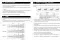
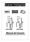
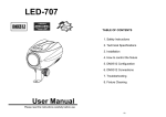
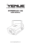
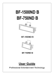
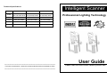
Technical Specifications
Intelligent Scanner
MH-635
MH-635B
MH-635S
Power
AC 120V 50 / 60Hz
AC 230 250V 50Hz
AC 120V 60Hz
AC 230 250V 50Hz
AC 120V 60Hz
AC 230 250V 50Hz
Fuse
T5A T3.15A
T6.3A T5A
T6.3A T5A
Lamps
EFP 12V 100W
ELC 24V 250W
ELC 24V 250W
Dimension
385x170x122mm
405x170x122mm
385x170x122mm
Weight
3.8kg
4.5kg
4.5kg
================================================================
For further requirements, contact the nearest authorized technical assistance office
================================================================
Professional Lighting Technology
User Guide
Please read the instructions carefully before use
E.
FIXTURE CLEANING
The cleaning of internal and external optical lenses and/or mirrors must be carried
out periodically to optimize light output. Cleaning frequency depends on the
environment in which the fixture operates: damp, smoky or particularly dirty
surroundings can cause greater accumulation of dirt on the unit’s optics.
•
•
•
INDEX
Clean with a soft cloth using normal glass cleaning products.
Always dry the parts carefully.
Clean the external optics at least once every 20 days. Clean the internal optics
A. GENERAL INSTRUCTIONS
at least every 30/60 days.
B. MAIN FEATURES
EC Declaration of Conformity
C. LAMP
We declare that our products (lighting equipments) comply with the
following specification and bears CE mark in accordance with the
provision of the Electromagnetic Compatibility (EMC) Directive
89/336/EEC.
EN55014-2: 1997 A1:2001, EN61000-4-2: 1995; EN61000-4-3:2002;
EN61000-4-4: 1995; EN61000-4-5: 1995, EN61000-4-6:1996,
EN61000-4-11: 1994.
&
Harmonized Standard
EN60598-1: 2000+ALL:2000+A12:2002
Safety of household and similar electrical appliances
Part 1 : General requirements
2D
D. HOW TO CONTROL THE UNIT
-----(1) By universal DMX controller
-----(2) Preprogrammed function
-----(3) By easy controller
E. FIXTURE CLEANING
( 2 ) Preprogram functions
The unit can be linked together in daisy chain as many as you need in master/slave
mode to perform the great built-in pre-programmed lighting shows triggered by
music.
In Master/Slave mode refer to the DMX settings below:
Master unit: DMX start address MUST be set to 001. (first DIP switch = ON, all
other are OFF)
Slave units: DMX start address may have any value but NOT 001 (example:
set the first 3 DIP switches to ON)
* 2-light show
Dipswitch 10 “off” means the unit works normally and “on” means inversion.
In order
to create a great light show, you can set dip switch 10 “on” on any unit that is linking
to the master unit to get contrast movement to the master unit, even if you have two
units only.
3D
Dipswitch 10 on the first ( Master ) unit is no use for the 2-light show as it
is the master unit that operates the light show.
( 3 ) By easy controller
The easy remote control is used only in master/slave mode.
By connecting to the 1/4” microphone jack of the first unit (its
DMX input plug is not used), you will find that the remote
control on the first unit will control all the other units for Stand
by, Function and Mode.
Built-in lighting shows triggered by Easy Controller:
Stand by
Function
Mode
Blackout the unit
Strobe
1. sync. strobe
2. two-light strobe
Strobe/ Sound
(LED off)
X/Y moving pattern
selection
(12 patterns)
Pattern/ Sound
(LED blinking)
Color/Gobo selection
Sound
(LED on)
A.
GENERAL INSTRUCTIONS
Please read the enclosed instructions carefully as they include important
points about safety for the installation, usage and maintenance of the unit.
WARNING
• Please keep this booklet with the unit for future consultation. If you sell the unit to
another user, be sure that the new user also receives this instruction booklet thus
giving them the necessary information about the use and general warnings
regarding the unit.
• Before the initial start-up, please unpack and carefully check all components in
case any damage may have occurred during shipping.
• Locate a suitable spot for your device where there is good ventilation. Also, make
sure that no ventilating fans or slots are blocked.
• Protect our environment! Please dispose of the packing boxes properly.
4D
• The electrical work that is necessary for installation must done by qualified
personnel.
• Start the address
• Always remember to unplug the unit from the main power before any service is
How to address your DMX512 system:
done. Do not open the unit. There are no serviceable parts inside.
1. Select the channels of DMX controller
• It is very important to ground the yellow/green conductor to earth in order to meet
2. Dipswitches
regulations for safety.
Dip
#1
#2
#3
#4
#5
#6
#7
#8
#9
Value
1
2
4
8
16
32
64
128
256
• Examples:
Channel 01:dip / on : #1(=1)
• Check the surrounding area and make sure there are no flammable liquids, water or
metal objects that could enter the fixture. If a foreign object enters the unit,
immediately disconnect the main power. Also, place the fixture in a well-ventilated
room at about 15 cm from the walls.
Channel 05:dip / on : #1, #3(1+4=5)
• Do not touch any wires during operation, as high voltage is hazardous.
Channel 09:dip / on : #1,#4(1+8=9)
• In the event of serious operating problems, stop using the unit immediately. Never
Channel 13:dip / on : #1,#3,#4(1+4+8=13)
try to repair the unit yourself. Repairs carried out by unqualified personnel can lead
to damage or malfunction. Please contact the nearest authorized Technical
Assistance Center. Always use genuine spare parts.
B.
MAIN FEATURES
D.
• The unit is a DMX512 scanner. It features full DMX512 control, 10 gobos/colors
HOW TO CONTROL THE UNIT
( 1 ) By universal DMX controller
plus open and white, focus adjustable accurate optics system and stepper motor
The DMX512 is widely used in intelligent lighting control, with a maximum of 512
with blackout feature. Fan cooled.
channels.
• It can be operated by DMX512 control or can be used as an individual unit without
controller.
• It can be linked together as many as required in master/slave mode, and perform
the great built-in programmed lighting shows triggered by music.
• Please use a 3 pin XLR cable/plug when connecting them together.
• It features different pre-programmed chase patterns.
C.
LAMP
• Always switch off the mains supply and never handle the lamp or luminaire when it
is hot.
• Do not touch the bulb with bare hands. If this does happen, clean the lamp with
denatured alcohol and wipe with a lint free cloth before installing.
A DMX512 system requires a controller, lighting equipment and cable. These are
5D
connected together in a “daisy chain” with the terminator at the end. The cable
cannot be branched or split to a “Y” cable.
The terminator requires a 90-120 Ohm 1/4 Watt resistor soldered between two
MH-635
signal cables.
The DMX512 uses a very high-speed signal. Inadequate or damaged cables, bad
solder joints or corroded connectors can easily distort the signal and shut down
the system. A reliable DMX512 system starts with good quality cables.
Each lighting unit needs to have an address set to receive the data sent by the
MH-635B
controller. The address number is between 0-511. The end of the DMX512
system should be terminated reducing signal errors.
3 pin XLR connectors are more popular than 5 pin XLR.
3 pin XLR: Pin 1: GND, Pin 2: Negative signal (-), Pin 3: Positive signal (+)
MH-635S
5 pin XLR: Pin 1: GND, Pin 2: Negative signal (-), Pin 3: Positive signal (+)