1
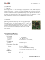
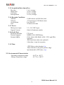
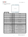
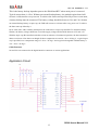
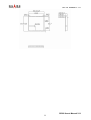
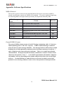
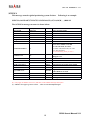
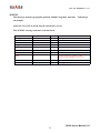
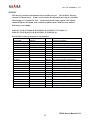
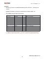
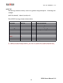
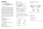
SR-90 Manual V1.0
GPS Engine Board Manual
SR-90
SiRF StarⅢ
Ⅲ
V 1.1
Made in Taiwan
2008/08/08
[email protected]
www.dagamagps.com
Free service hot-line(for mainland):400-820-1322
SR-90 Manual V1.0
Specifications subject to
change without prior notice!
Contents
1. Introduction
1.1 Overview
1.2 Features
……………………………………………………..…………. 2
…………………………………………………………………. 2
……………………………………………………………………. 2
2. Technical Specifications …………………………………………………… 2
2.1. Electrical Characteristics…………………………………………………. 2
2.2. Environmental Characteristics……………………………………..……… 3
2.3. Physical Characteristics……………………………………………...…..… 4
Appendix: Software Specifications
……………………………………..
9
SR-90 User’s Manual V1.1
1
SR-90 Manual V1.0
1. Introduction
1.1 Overview
SR-90 GPS module is a high performance receiver module for the Global Positioning
System (GPS) solution. It combines SiRF StarⅢ GPS single chip, LNA circuit, SAW filter,
oscillator, crystal and regulators into a land grid array module. The specified firmware is
pre-loaded into the built-in 4-Mbit Flash memory of SR-90 for GPS application. It can be
easily embedded into portable devices for GPS wireless communication.
1.2 Features
SiRF starⅢ high performance GPS Chip Set Very high sensitivity
(Tracking Sensitivity: -159 dBm) Extremely fast TTFF (Time To First
Fix) at low signal level Compact size (25.4mm * 25.4 mm * 3.3mm)
suitable for space-sensitive application One size component, easy
to mount on another PCB board Support NMEA 0183 and SiRF
binary protocol
2. Technical Specifications
2.1. Electrical Characteristics
2.1.1 General
Frequency
L1, 1575.42 MHz
C/A code
1.023 MHz chip rate
Channels
20 channels all in view tracking
2.1.2 Sensitivity
Tracking
-159 dBm typical
2.1.3 Accuracy (Open Sky)
Position
Time
2.1.4 Datum
Default
10 meters, 2D RMS
5 meters 2D RMS, WAAS enabled
1 microsecond synchronized to GPS time
WGS-84
SR-90 User’s Manual V1.1
2
SR-90 Manual V1.0
2.1.5 Acquisition Rate (Open Sky)
Hot start
1 sec, average
Warm start
38 sec, average
Cold start
42 sec, average
Reacquisition
0.1 sec, average
2.1.6 Dynamic Conditions
Altitude
Velocity
Acceleration
Jerk
18,000 meters (60,000 feet) max
515 meters/sec (1000 knots) max
Less than 4 G
20 meters/sec max
2.1.7 Power
Main power input
Supply Current
3.3 ± 5% VDC input
68mA (Continuous mode)
2.1.8 Serial Port
Electrical interface
Protocol support
Default NMEA
TTL level
NMEA-0183, SiRF Binary
GGA, GSA, GSV, RMC, (GLL, VTG, and ZDA
optional)
4800 baud rate (other rate optional)
8 bits data, 1 stop bit, no parity.
2.1.9 Time
1 PPS Pulse, pulse duration 1µs.
Time reference at the pulse positive edge.
Synchronized to GPS time, ±1µs.
2.2. Environmental Characteristics
Operating temperature range
Storage temperature range
-40 oC to +85 oC
-45 oC to +100 oC
SR-90 User’s Manual V1.1
3
SR-90 Manual V1.0
2.3. Physical Characteristics
Top view
Pin Assignment
Pin
Signal
Name
I/O
Description
1
VCC
I
DC Supply Voltage input
2
GND
G
Ground
3
Boot select
I
Boot mode
4567
RXA TXA
TXB RXB
IOOI
Serial port A Serial port A Serial port B Serial port B
8
GPIO14
I/O
General –purpose I/O
9
RF_ON
10
GND
G
Digital Ground
11 16
GND_A
G
Analog Ground
17
RF_IN
I
GPS Signal input
18
GND_A
G
Analog Ground
19
V_ANT_IN
I
Active Antenna Bias voltage
20
VCC_RF
O
Supply Antenna Bias voltage
21 22
V_BAT
Reset
II
Backup voltage supply Reset (Active low)
23
GPIO10
I/O
General purpose I/O
24 25 26
GPIO1
GPIO5
GPIO0
I/O
I/O
I/O
General purpose I/O General purpose I/O General purpose
I/O (support continuous power mode only)
27
GPIO13
I/O
General purpose I/O
I/O O
G
General purpose I/O One pulse per second Digital Ground
28 29 30
GPIO15
PPS GND
SR-90 User’s Manual V1.1
4
SR-90 Manual V1.0
Definition of Pin assignment
VCC
This is the main DC supply for a 3.3V ± 5% DC input power module board.
GND
GND provides the ground for digital part.
Boot select
Set this pin to high for programming flash.
RXA
This is the main receiver channel and is used to receive software commands to the board from SIRFdemo
software or from user written software.PS: Pull up if not used.
RXB
This is the auxiliary receiving channel and is used to input differential corrections to the board to enable
DGPS navigation.PS: Pull up if not used.
TXA
This is the main transmitting channel and is used to output navigation and measurement data to SiRFdemo or
user written software.
TXB
For user’s application (not currently used).
RF_ON
This pin indicates state of RF voltage.
RF_IN
This pin receiver signal of GPS analog .due to the RF characteristics of the signal the design has
to certain criteria. The line on the PCB from theantenna (or antenna connector) has to be a
controlled microstrip line at 50Ω
V_ANT_IN
This pin is reserved an external DC power supply for active antenna. If using 3.0V active antenna, pin 19 has
to be connected to pin 20. If using 3.3V or 12V active antenna, this pin has to be connected to 3.3V or 5Vpower
supply.
VCC_RF
This pin provides DC voltage 3.0 for active antenna. Reset This pin provides an active-low reset input to the
board. It causes the board to reset and start searching for satellites. If not utilized, it may be left open.
PPS
This pin provides one pulse-per-second output from the board, which is synchronized to GPS time. This is
not available in Trickle Power mode.
Backup battery (V_BAT)
SR-90 User’s Manual V1.1
5
SR-90 Manual V1.0
This is the battery backup input that powers the SRAM and RTC when main power is removed.
Typical current draw is 15uA. Without an external backup battery, the module/engine board will
execute a cold star after every turn on. To achieve the faster start-up offered by a hot or warm start,
a battery backup must be connected. The battery voltage should be between 2.0v and 5.0v. Without
an external backup battery or super cap, the TMP will execute a cold start after every power on. To achieve
the faster start-up offered by a
hot or warm start, either a battery backup must be connected or a super cap installed. To maximize battery
lifetime, the battery voltage should not exceed the supply voltage and should be between 2.5V and 3.6V.
With the super cap (B1) installed, and after at least ten minutes of continuous operation, the data retention is
about seven hours. Note that even though all other components are rated at –30 to +85 deg C, a typical super
cap is specified over a temperature range of –25 to +70 deg C and a typical rechargeable Lithium battery is
over –20 to +70 deg C.
GPIO Functions
Several I/Os are connected to the digital interface connector or custom applications.
Application Circuit
SR-90 User’s Manual V1.1
6
SR-90 Manual V1.0
(1) Ground Planes: SR-90 GPS receiver needs two different ground planes. The
GND_A pin(11、12、13、14、15、16、18) shall be connect to analog ground.
The GND pin(2 、10、30) connect to digital ground.
(2) Serial Interface: The Serial interface pin(RXA 、TX1、TXB 、RXB) is recommended
to pull up(10KΩ).
It can increase the stability of serial data.
(3) Backup Battery:
It’s recommended to connect a backup battery to V_BAT. In order to enable the
warm and hot start features of the GPS receiver. If you don’t intend to use a backup
battery, connect this pin to GND or open. If you use backup battery, shall need to
add a bypassing capacitor (10uF) at V_bat trace. It can reduce noise and increase
the stability.
(4) Antenna:
Connecting to the antenna has to be routed on the PCB. The transmission line must
to controlled impedance to connect RF_IN to the antenna or antenna connector of
your choice.
(5) Active antenna bias voltage:
The Vcc_RF pin (pin 20) is providing voltage 3.3V. If you use active antenna, you
can connect this pin to V_ANT_IN pin (pin 19) to provide bias voltage of active.
Mechanical Layout
SR-90 User’s Manual V1.1
7
SR-90 Manual V1.0
SR-90 User’s Manual V1.1
8
SR-90 Manual V1.0
Appendix: Software Specifications
NMEA Protocol
The interface protocol is based on the National Marine Electronics Association (NMEA)
interface specification, namely, the NMEA 0183 standard. The unit is capable of supporting
the following NMEA message formats specifically developed and defined by SiRF.
NMEA Message
Prefix
$GPGGA
$GPGLL
$GPGSA
$GPGSV
$GPMSS
$GPRMC
$GPVTG
$GPZDA
Format
Direction
Time, position and fix type data.
Latitude, longitude, time of position fix and status.
GNSS DOP and active satellites
Satellites in view.
Radio beacon signal-to-noise ratio, signal strength,
frequency, etc.
Recommended minimum specific GNSS data.
Speed and course over ground.
Out
Out
Out
Out
Date and time.
Out
Out
Out
Out
General NMEA Format
The general NMEA format consists of an ASCII string commencing with a ‘$’ character
and terminating with a <CR><LF> sequence. NMEA standard messages commence
with ‘GP’ then a 3-letter message identifier. The message header is followed by a comma
delimited list of fields optionally terminated with a checksum consisting of an asterix ‘*’
and a 2 digit hex value representing the checksum. There is no comma preceding the
checksum field. When present, the checksum is calculated as a bitwise exclusive of the
characters between the ‘$’ and ‘*’. As an ASCII representation, the number of digits in
each number will vary depending on the number and precision, hence the record length
will vary. Certain fields may be omitted if they are not used, in which case the field
position is reserved using commas to ensure correct interpretation of subsequent fields.
SR-90 User’s Manual V1.1
9
SR-90 Manual V1.0
$GPGGA
This message transfers global positioning system fix data.
Following is an example.
$GPGGA,161229.487,3723.2475,N,12158.3416,W,1,07,1.0,9.0,M, , , ,0000*18
The $GPGGA message structure is shown below:
Field
Message ID
UTC Time
Latitude
N/S Indicator
Longitude
E/W indicator
Example
$GPGGA
161229.487
3723.2475
N
12158.3416
W
Position Fix Indictor
1
Satellites Used
07
HDOP
MSL Altitude (2)
Units
Geoid Separation (2)
Units
1.0
9.0
M
Unit
0: Fix not available or invalid.
1: GPS SPS mode, fix valid.
2: Differ. GPS, SPS mode, fix valid
3-5: Not supported.
6: Dead Reckoning Mode, fix valid. (1)
Meter
Meter
Meter
Meter
Age of Diff. Corr.
Diff Ref. Station ID
Checksum
<CR> <LF>
Notes
GGA protocol header.
hhmmss.sss
ddmm.mmmm
N=north or S=south.
dddmm.mmmm
E=east or W=west.
Second
Number of satellites used to calculate fix.
Range 0 to 12.
Horizontal Dilution of Precision.
Altitude above mean seal level.
M stands for “meters”.
Separation from Geoids can be blank.
M stands for “meters”.
Age in seconds. Blank (Null) fields
when DGPS is not used.
0000
*18
Message terminator.
(1) Only apply to NMEA version 2.3 (and later) in this NMEA message description.
(2) SiRF does not support geoid corrections. Values are WGS84 ellipsoid heights.
SR-90 User’s Manual V1.1
10
SR-90 Manual V1.0
$GPGLL
This message transfers geographic position, latitude, longitude, and time.
an example.
Following is
$GPGLL,3723.2475,N,12158.3416,W,161229.487,A,A*41
The $GPGLL message structure is shown below:
Field
Message ID
Latitude
N/S Indicator
Longitude
E/W indicator
UTC Time
Status
Example
$GPGLL
3723.2475
N
12158.3416
W
161229.487
A
Mode
A
Checksum
<CR><LF>
*41
Unit
Notes
GLL protocol header.
ddmm.mmmm
N=north or S=south.
dddmm.mmmm
E=east or W=west.
hhmmss.sss
A: Data valid or V: Data invalid.
A=Autonomous, D=DGPS, E=DR
(Only present in NMEA version 3.00).
Message terminator.
SR-90 User’s Manual V1.1
11
SR-90 Manual V1.0
$GPGSA
This message transfers DOP and active satellites information.
Following is an example.
$GPGSA,A,3,07,02,26,27,09,04,15, , , , , ,1.8,1.0,1.5*33
The $GPGSA message structure is shown below:
Field
Message ID
Example
$GPGSA
Unit
Notes
GSA protocol header.
Mode
A
M: Manual, forced to operate in selected
2D or 3D mode.
A: Automatic switching between modes.
Mode
3
1
2
3
Satellites Used (1)
Satellites Used (1)
…
Satellites Used (1)
PDOP
HDOP
VDOP
Checksum
<CR> <LF>
07
02
Fix not available.
2D position fix.
3D position fix.
SV on channel 1.
SV on channel 2.
..
SV on channel 12.
1.8
1.0
1.5
*33
Message terminator.
(1) Satellites used in solution.
SR-90 User’s Manual V1.1
12
SR-90 Manual V1.0
$GPGSV
This message transfers information about satellites in view. The $GPGSV message
structure is shown below. Each record contains the information for up to 4 channels,
allowing up to 12 satellites in view. In the final record of the sequence the unused
channel fields are left blank with commas to indicate that a field has been omitted.
Following is an example.
$GPGSV,2,1,07,07,79,048,42,02,51,062,43,26,36,256,42,27,27,138,42*71
$GPGSV,2,2,07,09,23,313,42,04,19,159,41,15,12,041,42*41
The $GPGSV message structure is shown below:
Field
Message ID
Number of messages (1)
Message number
Satellites in view
Satellite ID
Elevation
Azimuth
SNR (C/N0)
Satellite ID
Elevation
Azimuth
SNR (C/N0)
Satellite ID
Elevation
Azimuth
SNR (C/N0)
Satellite ID
Elevation
Azimuth
SNR (C/N0)
Checksum
<CR> <LF>
Example
$GPGSV
2
1
07
07
79
048
42
02
51
062
43
26
36
256
42
27
27
138
42
*71
Unit
degree
degree
dBHz
degree
degree
dBHz
degree
degree
dBHz
degree
degree
dBHz
Notes
GSA protocol header.
Number of messages, maximum 3.
Sequence number, range 1 to 3.
Number of satellites currently in view.
Channel 1, ID range 1 to 32.
Elevation of satellite, maximum 90.
Azimuth of satellite, range 0 to 359.
Range 0 to 99, null when not tracking.
Channel 2, ID range 1 to 32.
Elevation of satellite, maximum 90.
Azimuth of satellite, range 0 to 359.
Range 0 to 99, null when not tracking.
Channel 3, ID range 1 to 32.
Elevation of satellite, maximum 90.
Azimuth of satellite, range 0 to 359.
Range 0 to 99, null when not tracking.
Channel 4, ID range 1 to 32.
Elevation of satellite, maximum 90.
Azimuth of satellite, range 0 to 359.
Range 0 to 99, null when not tracking.
Message terminator.
(1) Depending on the number of satellites tracked multiple messages of GSV data may be required.
SR-90 User’s Manual V1.1
13
SR-90 Manual V1.0
$GPMSS
This message transfers information about radio beacon signal-to-noise ratio, signal
strength, frequency, etc. Following is an example.
$GPMSS,55,27,318.0,100,1,*57
The $GPMSS message format is shown below.
Field
Message ID
Signal Strength
Signal-to-Noise Ratio
Beacon Frequency
Beacon Bit Rate
Example
$GPMSS
55
27
318.0
100
Channel Number (1)
1
Checksum
<CR> <LF>
*57
Unit
Notes
MSS protocol header.
dB
dB
kHz
SS of tracked frequency.
SNR of tracked frequency.
Currently tracked frequency.
Bits per second.
The channel of the beacon being used if a
multi-channel beacon receiver is used.
Message terminator.
(1) Fields marked in italic red apply only to NMEA version 2.3 (and later) in this NMEA message description.
SR-90 User’s Manual V1.1
14
SR-90 Manual V1.0
$GPRMC
This message transfers recommended minimum specific GNSS data.
example.
Following is an
$GPRMC,161229.487,A,3723.2475,N,12158.3416,W,0.13,309.62,120598, ,*10
The $GPRMC message format is shown below.
Field
Message ID
UTC Time
Status
Latitude
N/S Indicator
Longitude
E/W indicator
Speed over ground
Course over ground
Date
Magnetic variation (1)
Mode (2)
Checksum
<CR> <LF>
Example
$GPRMC
161229.487
A
3723.2475
N
12158.3416
W
0.13
309.62
120598
Unit
knot
degree
degree
A
*10
Notes
RMC protocol header.
hhmmss.sss
A: Data valid or V: Data invalid.
ddmm.mmmm
N=north or S=south.
ddmm.mmmm
E=east or W=west.
Speed over ground
Course over ground
ddmmyy, current date.
Not used.
A=Autonomous, D=DGPS, E=DR.
Message terminator.
(1) SiRF does not support magnetic declination. All “course over ground” data are geodetic WGS84 directions.
(2) Fields marked in italic red apply only to NMEA version 2.3 (and later) in this NMEA message description.
SR-90 User’s Manual V1.1
15
SR-90 Manual V1.0
$GPVTG
This message transfers velocity, course over ground, and ground speed.
example.
Following is an
$GPVTG,309.62,T, ,M,0.13,N,0.2,K,A*23
The $GPVTG message format is shown below.
Field
Message ID
Course (true)
Reference
Course (magnetic)
Reference (1)
Speed
Units
Speed
Units
Mode (2)
Checksum
<CR> <LF>
Example
$GPVTG
309.62
T
Unit
degree
degree
M
0.13
N
0.2
K
A
*23
knot
km/hr
Notes
VTG protocol header.
Measured heading
T = true heading
Measured heading
M = magnetic heading (1)
Speed in knots
N = knots
Speed
K = km/hour.
A=Autonomous, D=DGPS, E=DR.
Message terminator.
(1) SiRF does not support magnetic declination. All “course over ground” data are geodetic WGS84 directions.
(2) Fields marked in italic red apply only to NMEA version 2.3 (and later) in this NMEA message description.
SR-90 User’s Manual V1.1
16
SR-90 Manual V1.0
$GPZDA
This message transfers UTC Time and Date.
Following is an example.
$GPZDA,181813,14,10,2003,00,00*4F
The $GPZDA message format is shown below.
Field
Message ID
Example
$GPZDA
Unit
Notes
ZDA protocol header.
UTC Time
181813
Either using valid IONO/UTC or estimated
from default leap seconds.
UTC Day
UTC Month
UTC Year
Local zone hours
Local zone minutes
Checksum
<CR> <LF>
14
10
2003
00
00
*4F
01 to 31, day of month.
01 to 12.
1980 to 2079.
Offset from UTC (set to 00).
Offset from UTC (set to 00).
Message terminator.
All Rights Reserved
SR-90 User’s Manual V1.1
17