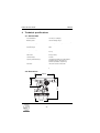
1
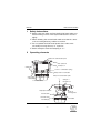
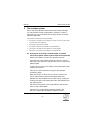
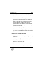
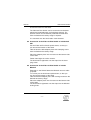
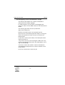
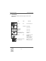
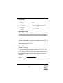
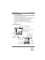
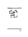
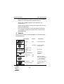
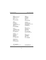
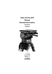
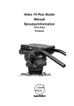
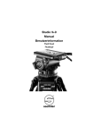
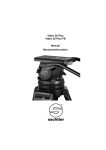
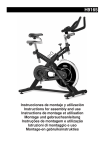
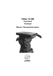
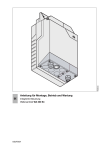
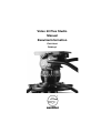
Video 60 Plus Studio
Manual
Benutzerinformation
Fluid Head
Fluidkopf
© by sachtler®. Alle Rechte vorbehalten / All rights reserved
Version: 2.9/02/12
Ausgabedatum / Issue date: 02/12
Bestellnr. / Order no.: sko16t080a
Originalbetriebsanleitung/Original User Manual
We want you to receive
Sachtler products that are
always state of the art.
Wir wollen, dass Ihre Sachtler
Produkte immer auf dem
aktuellsten Stand sind.
Therefore we reserve the right
to make changes based on
technical advances.
Deswegen behalten wir uns
technische Änderungen vor.
sachtler®
Vitec Group Videocom Division
www.vitecgroup.com
Erfurter Strasse 16
Postfach / P.O.BOX 2039
D-85386 Eching
D-85380 Eching
Germany
Germany
Telefon: (+49) 89 321 58 200
Telefax: (+49) 89 321 58 227
E-Mail: [email protected]
Homepage: http://www.sachtler.com
Table of contents
1
Safety instructions ..........................................................................1
2
Operating elements ........................................................................1
3
Operation ........................................................................................2
3.1
Levelling of the fluid head .....................................................2
3.2
Removing the V-plate ............................................................2
3.3
Mounting of the camera ........................................................2
3.4
Removing of the camera .......................................................3
3.5
Positioning of the camera......................................................3
3.6
Adjusting the camera’s counterbalance................................4
3.7
Setting of the Damping..........................................................6
3.8
Brakes....................................................................................6
3.9
Connection to teleprompter ..................................................6
3.10 Change of the batteries .........................................................7
3.11 Transport setting of damping, counterbalance and
brakes ....................................................................................7
4
5
Technical specifications .................................................................8
4.1
General data ..........................................................................8
4.2
Dimensions ............................................................................8
The modular system .......................................................................9
5.1
Conversion of the Video 60 Plus Studio to include
Touch & Go quick release system with camera plate 35......9
5.2
Conversion of pan bars and rosette....................................10
5.3
Conversion of Video 60 Plus Studio to include
Multi Disc .............................................................................10
5.4
Conversion of the Video 60 Plus Studio to include
half ball ................................................................................11
5.5
Conversion of the Video 60 Plus Studio to include
Mitchell ................................................................................11
5.6
Disengaging of fixed couterbalance springs .......................12
6
Accessories...................................................................................14
7
Warranty........................................................................................15
-I-
Inhaltsverzeichnis
1
Sicherheitshinweise ......................................................................17
2
Bedienelemente ............................................................................17
3
Betrieb ..........................................................................................18
3.1
Nivellieren des Fluidkopfes..................................................18
3.2
Entnehmen der V-Platte .....................................................18
3.3
Einsetzen der Kamera ........................................................18
3.4
Entnehmen der Kamera.......................................................19
3.5
Zentrieren des Kameragewichts..........................................19
3.6
Einstellen der Kamerabalance ............................................20
3.7
Einstellen der Dämpfung .....................................................22
3.8
Bremsen...............................................................................22
3.9
Teleprompteranschluß .........................................................23
3.10 Austausch der Batterien ......................................................23
3.11 Transportstellung von Dämpfung, Gewichtsausgleich
und Bremsen .......................................................................23
4
5
Technische Daten .........................................................................24
4.1
Allgemeine Daten.................................................................24
4.2
Abmessungen ......................................................................25
Das Baukastensystem ..................................................................26
5.1
Umbau des Video 60 Plus Studio auf Touch & Go
Verschluß mit Kameraplatte 35 ...........................................26
5.2
Umbau der Schwenkarme mit Rosette ...............................27
5.3
Umbau des Video 60 Plus Studio auf Multi Disc ................28
5.4
Umbau des Video 60 Plus Studio auf Halbkugel ................28
5.5
Umbau des Video 60 Plus Studio auf Mitchell....................28
5.6
Abschalten der festen Federn .............................................29
6
Zubehör.........................................................................................30
7
Gewährleistung .............................................................................31
- II -
- III -
- IV -
Manual
1
Safety instructions
Á Before using the Video 60 Plus Studio fluid head make sure
Á
Á
Á
2
Video 60 Plus Studio
that all 4 fixing screws of the tripod’s flat base are secured
tightly.
When releasing the vertical brake make sure that the camera is secured against any sudden movement.
Do not operate the fluid head upside down without the
necessary securing devices, i.e. ropes etc.
Before transport reset fluid damping to “0”.
Operating elements
Spindle of the Camera balance plate
V-plate-lock
Tilt safety lock
Vertical brake
Lever for ½ counterbalance springs
Battery holder for touch bubble
Clamp of the camera balance plate
Vertical setting
of fluid damping
Safety pin of
the V-plate lock
Counterbalance knob
Teleprompter connection
VIDEO 60
Plus
Rosette for
mounting panbar
Horizontal brake
Horizontal setting
of fluid damping
-1-
Touch bubble
Video 60 Plus Studio
3
Manual
Operation
3.1 Levelling of the fluid head
Touch Bubble
The Video 60 Plus Studio has a self illuminating spirit
bubble which allows easy levelling even under unfavourable lighting conditions.
The illumination is activated by strong tapping on the
bubble. The bubble will light up to 45 seconds.
3.2 Removing the V-plate
Push the safety pin of the V-plate lock to the front and
swing it into horizontal position. Pull the V-plate locking
lever out. The V-plate is now released and can be removed by pulling it backwards.
3.3 Mounting of the camera
Attach the camera V-plate to the tripod adapter plate
(camera accessory) around the camera’s centre of gravity.
Á Turn the counterbalance knob to position 9
Á Apply horizontal brake and release vertical brake
Á The springs of the counterbalance engage automatically by tilting the camera through the horizontal position (audible clicking).
Lock the head with the tilt safety lock.
The blocking and clicking into position of the tilt safety
lock is achieved by pulling out the red knob and turning it
90°. Green marking on the red knob becomes invisible.
Make sure that the tilt safety lock has engaged (the head
can’t be tilted any more).
Á Move camera with V-plate from the back along the
guides until it reaches the end stop.
-2-
Manual
Video 60 Plus Studio
Á Push the locking lever in and backwards until it touches the head and secure locking of the V-plate by lifting safety pin.
3.4 Removing of the camera
Á Lock the head with the tilt safety lock.
The blocking and clicking into position of the tilt safety
lock is achieved by pulling out the red knob and turning it
90°. Green marking on the red knob becomes invisible.
Make sure that the tilt safety lock has engaged (the head
can’t be tilted any more).
Á Push the safety pin of the V-plate lock to the front and
swing it into horizontal position. Pull the V-plate locking
lever out. The camera with V-plate is now released and
can be removed by pulling it backwards.
Caution: If necessary the camera should be held by two
persons, as the weight can approach
65 kg / 143 lb.
3.5 Positioning of the camera
Á Hold the camera by securing the pan bar.
Á Apply horizontal brake and release vertical brake and
tilt safety lock by pulling out the red knob and turning it
90°. Green marking on the red knob becomes visible
(rocking the pan bars up and down will facilitate this).
Á Select 0 on the vertical drag adjustment ring.
Á Open the lock of camera sliding balance plate.
On the Video 60 Plus Studio the lock of camera sliding
balance plate is opened on the left side of the fluid head.
Á By turning the spindle forwards and backwards move
the camera until you have reached a position where
the camera is balanced horizontally. Rear-heavy cameras are moved to the front by turning the spindle clockwise,
-3-
Video 60 Plus Studio
Manual
front-heavy cameras are moved to the back by turning
the spindle anti-clockwise. You will find it easier when
holding the camera in a horizontal position.
Á Secure sliding balance plate with clamping lever
(spindle drive is self-locking, clamping serves to eliminate play).
On the Video 60 Plus Studio the lock of balance plate is
closed on the left side of the fluid head.
Caution: If you can’t manage to centre the camera, you
should move the V-plate to a different position
on the tripod mounting adapter.
3.6 Adjusting the camera’s counterbalance
Á Hold the camera by securing the pan bar.
Á Turn the counterbalance knob to that number which
best compensates for the weight of the camera.
Á After each spring is released, check if the camera will
remain in a tilted position, without moving upwards or
downwards significantly.
Engaging or disengaging the right lever (small weight symbol) will apply or release half a spring which will help to
select optimum counterbalance. When spring is engaged
lever should be in an upright position, metal pin is not
visible - if disengaged metal pin inside the lever is visible.
Á Please note: A lower counterbalance setting becomes
immediately effective in any tilt position. An increase of
the counterbalance setting will only be effective in the
horizontal position (springs must click in audibly).
3.6.1 Engaging and disengaging of fixed counterbalance
springs (should only be performed in special situations)
The Video 60 Plus Studio has 4 fixed counterbalance
springs which are always engaged in position "1" of the
counterbalance knob. In certain situations it may be
-4-
Manual
Video 60 Plus Studio
necessary to change this pre-setting - e.g. you may wish
to disengage some springs in order to suit an ENG
camera. If you disengage all 4 springs, position "1" of
the counterbalance knob will spin free and you would
compensate by the strength of the right lever only (half a
spring).
All this is possible through a fairly simple procedure:
Á apply the tilt safety lock
Á open the lock of the balance plate by pushing the
red lever underneath the balance plate as far as
possible.
Á keep on turning the knob of the spindle to the left
until the balance plate is in the very rearmost position
You will see 4 tiny holes in the base plate above the 4
counterbalance fixing points (only from serial no. 60300
upwards)
Á you may now screw in (increasing of counterbalance strength) or screw out (decreasing of counterbalance strength) the hexagonal screws. For this you
should use an allen key #2.
Caution: the screws always remain inside the head. A
counterbalance spring is dis-engaged if the screw's head is
flush with the surface of the housing, i.e. it should not stick
out. The spring is engaged if you can't see the silver head of
the screw anymore because the screw is screwed in.
Á bring back the balance plate into its normal position.
Á apply the lock of the balance plate
Á open the tilt safety lock.
-5-
Video 60 Plus FB
Manual
3.7 Setting of the Damping
The Video 60 Plus Studio is equipped with nine damping
levels horizontally and vertically and a zero setting. By
turning the vertical setting and the horizontal setting one
selects the desired level of the fluid damping.Turn the setting ring to ”0” in order to switch off the damping completely. Make sure that you always turn the setting to the next
indexed position. Engage the retainer pins by slowly panning or tilting the camera.
ATTENTON: Panning or tilting the camera with settings
between the indexed positions can damage the retainer
pins and/or disks.
If you set the setting rings on the same index number
(e. g. ”3”) the degree of the horizontal and vertical damping is identical and thus enables precise diagonal panning movements without jerks and vibrations.
3.8 Brakes
The horizontal brake applies the lock for the pan and the
vertical brake for the tilt movement. Both brakes are vibrationless and can be used during shooting.
3.9 Connection to teleprompter
The Video 60 Plus Studio has two tapped holes at the
front to attach teleprompters.
3.10 Change of the batteries
The illumination is powered by three standard type button
cells (625 U or LR9) located in the battery holder, which
can be opened with a sharp object such as a screwdriver.
Make sure to insert the new batteries according to the
”plus” and ”minus” symbols as indicated in the covering
plate.The batteries last for about 2000 illumination cycles.
-6-
Manual
Video 60 Plus FB
3.11 Transport setting of damping, counterbalance
and brakes
To ensure smooth operation of the setting rings for the
damping over the long life time period of the fluid head,
you should turn both setting rings from position “0” to
maximum position, before and after the use of the fluid
head.
Setting during transportation: the most important issue is
to open both brakes - horizontal and vertical.
Counterbalance and damping should be set to maximum
position.
-7-
Video 60 Plus Studio
Technical specifications
4.1 General data
Counterbalance:
137 Nm (in 18 Steps)
Balance plate:
120 mm sliding range
Grades of damping:
horizontally and vertically 9 each and 0
Tilt angle:
+90 ° / -75 °
Panning range:
360 °
Temperature range:
-40 °C to 60 °C
Weight:
9,4 kg
Max. load:
65 kg (143 lb)
camera fitting:
V-Plate
Tripod / pedestal fitting:
integrated flat base for all OB tripods
and Multi Disc for Quickfix and
Sachtler pedestals, respectively
Pan bars :
two front sections ø 28.5 mm
Batteries:
3 each 625 U or LR9
4.2 Dimensions
200 mm
235 mm
91,5 mm
4
Manual
124 mm
-8-
Manual
5
Video 60 Plus Studio
The modular system
Due to the Video 60 Plus Studio fluid heads modular design
you may perform certain modifications yourself. In order to
safe time you can do all work with an allen wrench #4 unless
otherwise specified.
The following modifications can be performed:
Á Conversion of the Video 60 Plus Studio to include Touch & Go quick release system with camera plate 35
Á Conversion of pan bars and rosette
Á Conversion of Video 60 Plus Studio to include Multi Disc
Á Conversion of the Video 60 Plus Studio to include half ball
Á Conversion of the Video 60 Plus Studio to include Mitchell
5.1 Conversion of the Video 60 Plus Studio to include
Touch & Go quick release system with camera plate 35
Remove the fixation screw in the spindles top end.
Open the lock of the balance plate and keep on turning
the knob of the spindle to the left until you can remove the
balance plate.
Loosen the 4 screws (now visible) of the base plate underneath and remove it.
Take at your hand the EFP set up from the Sachtler
accessory range.
With this set up it is likely that you have to remove the
Touch & Go balance plate from the base plate first.
Release the camera plate from the EFP set up. Grasp the
locking lever with your thumb and index and pulldown the
red safety button.
Move the locking lever as far as possible to the left and
take out the camera plate.
Open the lock of the balance plate by pushing the
red lever underneath the balance plate to the left.
-9-
Video 60 Plus Studio
Manual
Turn the spindle knob of the EFP set up until you see an
allen screw size 4 opening in the camera plate receptacle.
Take out this screw.
Open the 2 screws of the spindle fixation with allen
wrench # 2 and remove the fixation piece.
Keep on turning the knob of the spindle to the left until
you can remove the balance plate.
Screw the base plate of the Touch & Go balance plate
onto the head. Fasten the allen screws hand-tight.
Guide the balance plate with spindle into the base plate.
Turn the spindle to the right until you can see it coming
out at the front of the head.
Place the fixation piece and tighten it with the 2 allen
screws (allen wrench #2). The spindle is now fastened.
Secure the balance plate by screwing allen screw size 4
into the hole of camera plate’s receptacle at the provided
place.
The conversion is done.
5.2 Conversion of pan bars and rosette
Open the 4 screws of the pan bar rosette and remove it.
If this is not possible hammer the positioning pins through
to the inside.
Replace the rosette against another one from the Sachtler
accessory range and position it first with the two pins.
Place the 4 allen screws and fasten them hand-tight.
Now you can use other pan bars.
5.3 Conversion of Video 60 Plus Studio to include Multi
Disc
Put the Video 60 Plus Studio upside down, so that you
can
- 10 -
Manual
Video 60 Plus Studio
access the bottom of the head.
The Video 60 Plus Studio can be mounted onto flat base
tripods and pedestals with 4 bolt flat base directly. For
Quickfix mount and all Sachtler pedestals the Multi Disc
from the Sachtler accessory range is required.
It is mounted onto the fluid heads 4 bolt flat base.
5.4 Conversion of the Video 60 Plus Studio to include half
ball
Put the Video 60 Plus Studio upside down, so that you
can access the bottom of the head.
Take at hand the ball adapter piece with clamping screw
from the Sachtler accessory range.
Place the adapter piece into the recess at the bottom side
of the head.
Fasten hand-tight the 4 allen screws.
The fluid head is tightened onto the tripod via the clamping screw.
5.5 Conversion of the Video 60 Plus Studio to include
Mitchell
Especially in the United States the Mitchell mount is widely spread.
To convert put the fluid head upside down, so that you
can access the bottom of the head.
Take the Mitchell adapter piece with locking knob from the
Sachtler accessory range.
Place the adapter piece into the recess at the bottom side
of the head.
The fluid head is tightened onto the tripod via the Mitchell
locking knob.
- 11 -
Video 60 Plus Studio
Manual
5.6 Disengaging of fixed counterbalance springs
The Video 60 Plus Studio has 4 fixed counterbalance
springs which are always engaged.
In certain situations you may wish to disengage some
springs in order to suit an ENG camera on the Video 60 Plus
Studio.
The following procedure has to be performed:·
Apply the tilt safety lock.
Remove the fixation screw in the spindles top end.
Open the lock of the balance plate and keep on turning the
knob of the spindle to the left until you can remove the
balance plate.
Loosen the 4 screws (now visible) of the base plate underneath and remove it.
4 tiny holes in the top of the housing are visible now. They
contain 4 hexagonal screws which are responsible for securing the fixed springs.
You have to loosen the screws in order to decrease the
counterbalance strength and vice versa to set back to the
initial position.
For this you should use an allen key #2.
- 12 -
Manual
Video 60 Plus Studio
Caution: The screws always remain inside the head!
A counterbalance spring is dis engaged if the screw's head
is flush with the surface of the housing, i.e. it should not
stick out. The spring is engaged if you can't see the silver
head of the screw anymore because the screw is screwed in
completely.
For reassembling screw the base plate onto the head.
Fasten the allen screws hand-tight.
Guide the balance plate with spindle into the base plate.
Turn the spindle to the right until you can see it coming out
at the front of the head.
Place the fixation screw in the spindles top end and tighten it. The spindles is now fastened.
Open the tilt safety lock.
- 13 -
Video 60 Plus Studio
6
Benutzerinformation
Accessories
Parts from the Sachtler accessory range in order of their
appearance:
Part:
Code:
Used with:
EFP Set up
6051
with camera plate 35
Rosette
sko16b0547 with Panbar
# 3270 / 3271
Pan bar backright piece
Pan bar back
left piece
B-3073-100
B-3074-100
Half balll adapter piece
with clamp screws 6052
conversion to
Half ball
Multi Disc
for Video 60 Plus EFP/
Studio in
conjunction with
Quickfix and Sachtler
tripods / pedestals
3914
Mitchelladapter piece 6053
with clamp screws
- 14 -
for Video 60 Plus EFP/
and
Video 60 Plus Studio
Video 60 Plus Studio
Manual
Case 60 FB
Code No.:
9506
Weight of case:
6kg / 13.2lb
Total weight:
16kg / 35.2 lb (case incl. Video 60 Plus
Studio)
Dimensions:
290mm x 410 mm x 330 mm
11.4" x 16.1" x 13"
Material:
Aluminium
ENG adapter plate
When using an ENG camera we recommend ordering the ENG
adapter plate (Code No. 3083). This guarantees a safe connection of the ENG camera with the Video 60 Plus Studio without
any play.
Cable clamp
A cable clamp (Code No. 6054) can be attached to the side of
the Video 60 Plus Studio fluid head. This will anchor up to three
Video cables of different size.
7
Warranty
Warranty expires if:
Á the fluid head was operated improperly or not in line with
the specified technical data, or
Á the head housing was opened by unauthorised personnel.
We reserve the right to make changes based on technical
advances.
Please register at www.sachtler.com for an extended warranty
period.
- 15 -
Manual
Video 60 Plus Studio
- 16 -
Video 60 Plus Studio
1
Sicherheitshinweise
Á Vor dem Gebrauch des Video 60 Plus Studio Fluidkopfes ist
Á
Á
Á
2
Benutzerinformation
sicherzustellen, daß die 4 Befestigungsschrauben im StativFlachboden fest angezogen sind.
Beim Lösen der Vertikalbremse muß sichergestellt sein, daß
die Kamera gegen plötzliche Bewegung gesichert ist.
Kopfüber darf der Fluidkopf nur mit ausreichender
Sicherung (z.B. Stahlseile) eingesetzt werden.
Vor dem Transport die Steuerringe der Dämpfung auf “0”
stellen.
Bedienelemente
Einstellknopf der Kamera Balanceplatte
V-Platte Verrieglung
Aufbau-Arretierung
Kipphebel für ½ Gewichtsausgleichfeder
Batterie fach der selbstleuchtende Libelle
Klemmung der Balanceplatte
Vertikalbremse
Sicherheitsstift für
Keilplattenverrieglung
Steuerring der
Vertikaldämpfung
Drehknopf zur
Einstellung des
Gewichtsausgleiches
Teleprompteranschluß
Horizontalbremse
Steuerring der
Horizonzaldämpfung
- 17 -
VIDEO 60
Plus
Rosette zur
Schwenkarm
befestigung
selbstleuchtende Libelle
Benutzerinformation
3
Video 60 Plus Studio
Betrieb
3.1 Nivellieren des Fluidkopfes
Beleuchtete Wasserwaage (Libelle)
Der Video 60 Plus Studio verfügt über eine selbstleuchtende Libelle, um auch bei ungünstigen Lichtverhältnissen
leicht nivellieren zu können.
Durch kräftiges Antippen der Libelle wird die Beleuchtung
aktiviert. Die Libelle leuchtet bis zu 45 Sekunden.
3.2 Entnehmen der V-Platte
Schieben Sie den Sicherungsstift der V-PlattenVerriegelung nach vorne und stellen ihn in die horizontale
Position. Ziehen Sie den V-Platten-Verriegelungshebel
nach vorne und dann nach außen. Die V-Platte wird freigegeben und kann nach hinten herausgezogen werden.
3.3 Einsetzen der Kamera
Befestigen Sie die V-Platte ungefähr im Schwerpunkt der
Kamera an der Stativadapterplatte (Kamera Zubehör).
Á Stellen Sie den Drehknopf des Gewichtsausgleichs auf
Position 9.
Á Schließen Sie Horizontalbremse und öffnen Sie die
Vertikalbremse.
Á Achten Sie darauf, daß die Federn des Gewichtsausgleiches einrasten, indem Sie den Kopf durch die
Horizontale neigen (hörbares Einrasten).
Á Blockieren Sie den Fluidkopf mit der AufbauArretierung.
Das Sperren und Einrasten der Aufbau-Arretierung geschieht durch Herausziehen des roten Knopfes und Drehung um 90°. Grüne Markierung am Knopf verschwindet.
Vergewissern Sie sich, daß die Aufbau-Arretierung eingerastet und der Kopf in der Horizontalen blockiert ist.
- 18 -
Video 60 Plus Studio
Benutzerinformation
(Der Kopf läßt sich mittels der Schwenkarme nicht mehr
neigen.)
Beim Einsetzen der Kamera mit V-Platte schieben Sie
diese von hinten in die V-Platten-Führung der Balanceplatte bis zum Anschlag.
Á Drücken Sie den Verriegelungshebel nach innen und
nach hinten bis er am Kopf anliegt und sichern Sie die
V-Platten-Verriegelung durch Hochklappen des
Sicherungsstiftes.
3.4 Entnehmen der Kamera
Á Blockieren Sie den Fluidkopf mit der AufbauArretierung.
Das Sperren und Einrasten der Aufbau-Arretierung geschieht durch Herausziehen des roten Knopfes und Drehung um 90°. Grüne Markierung am Knopf verschwindet.
Vergewissern Sie sich, daß die Aufbau-Arretierung eingerastet und der Kopf in der Horizontalen blockiert ist. (Der
Kopf läßt sich mittels der Schwenkarme nicht mehr neigen.)
Á Schieben Sie den Sicherungsstift der V-PlattenVerriegelung nach vorne und stellen ihn in die horizontale Position. Ziehen Sie den V-Platten-Verriegelungshebel nach vorne und dann nach außen. Die Kamera
mit V-Platte wird freigegeben und kann nach hinten
herausgezogen werden.
Bitte beachten Sie: Bei Auf- und Abbau einer Kamera sollte diese gegebenenfalls zu zweit
gehalten werden, da bis zu 65 kg
Kameragewicht wirksam werden können.
3.5 Zentrieren des Kameragewichts
Á Halten Sie den Kopf mittels Schwenkarm fest.
- 19 -
Benutzerinformation
Video 60 Plus Studio
Á Bei geschlossener Horizontalbremse und geöffneter
Á
Á
Vertikalbremse lösen Sie nun die Aufbau-Arretierung
durch Herausziehen des roten Knopfes und Drehung
um 90°. (Durch Heben und Drücken der Schwenkarme
erleichtern Sie das Öffnen.)
Drehen Sie den vertikalen Steuerring auf Position 0.
Lösen Sie die Klemmung der Kamera-Balanceplatte
Beim Video 60 Plus Studio wird der Klemmhebel an der
linken Seite des Kopfes geöffnet.
Á Durch Vor- und Zurückdrehen der Spindel verschieben
Sie die Kamera so lange bis Sie die Position gefunden
haben, in der die Kamera horizontal ausbalanciert ist.
Hecklastige Kameras werden durch Rechtsdrehen an
der Spindel nach vorne verschoben, frontlastige
Kameras durch Linksdrehen nach hinten. Sie erleichtern
das Verschieben, indem Sie die Kamera horizontal halten.
Á Sichern Sie die Balanceplatte mit dem Klemmhebel
(der Spindeltrieb ist selbsthemmend, die Klemmung
dient zur Beseitigung von Spiel).
Beim Video 60 Plus Studio wird der Klemmhebel an der
linken Seite des Kopfes geschlossen.
Bitte beachten Sie: Falls es Ihnen nicht gelingt die
Kamera zu zentrieren, schrauben Sie
die V-Platte an eine andere Position
der Stativadapterplatte.
3.6 Einstellen der Kamerabalance
Á Halten Sie die Hand am Schwenkarm und schalten Sie
über den Drehknopf des Gewichtsausgleichs schrittweise Ausgleichsfedern ab.
Á Testen Sie nach jeder abgeschalteten Feder, ob die
Kamera in der geneigten Stellung annähernd stehen
bleibt, d.h. die Kamera sollte in jeder Neigeposition
weder stark nach unten abkippen noch nach oben
zurückfedern.
- 20 -
Video 60 Plus Studio
Benutzerinformation
Á Mit dem rechten Kipphebel (kleines Gewichtssymbol)
kann eine halbe Feder geschaltet werden. Wählen Sie
durch Zu- oder Wegschalten dieser Feder den optimalen Gewichtsausgleich. (Bei zugeschalteter Feder steht
der Kipphebel aufrecht, Stahlstift ist nicht sichtbar. Bei
weggeschalteter Feder ist der Stahlstift im Kipphebel
sichtbar).
Bitte beachten Sie: Das Verringern der Ausgleichskraft
wird in jeder Neigeposition sofort wirksam, das Erhöhen
jedoch nur in Horizontalstellung (Federn rasten hörbar
ein).
3.6.1 Ab- bzw. Zuschalten der festeingestellten
Ausgleichsfedern (sollte nur in Ausnahmesituationen
durchgeführt werden)In der Position "1" des
Drehknopfes des Gewichtsausgleiches, der sogenannten
Grundstellung, sind 4 Gewichtsausgleichsfedern fest im
Eingriff, d.h. man kann sie nicht unmittelbar abschalten.
In bestimmten Situationen kann es jedoch von Vorteil
sein, diese Einstellung zu ändern; um z.B. das geringere
Gewicht beim Einsatz einer EB-Kamera zu kompensieren, können Sie bis maximal 4 Federn abschalten. In
diesem Fall würde in Position "1" des Drehknopfes des
Gewichtsausgleiches nur mit dem rechten Kipphebel
(halbe Feder) kompensiert. Gehen Sie wie folgt vor:
Á blockieren Sie den Fluidkopf mit der AufbauArretierung
Á lösen Sie die Klemmung der Kamera-Balanceplatte
indem Sie den vorderen roten Hebel unterhalb der
Balanceplatte nach links oben ziehen
Á drehen Sie den Knopf der Spindel so lange nach
links bis die Balanceplatte den hinteren Anschlag
erreicht hat
4 kleine Bohrungen werden nun im Boden der
Grundplatte sichtbar (erst ab Seriennummer 60300).
Diese sind exakt über den Befestigungsschrauben der
festen Ausgleichsfedern.
- 21 -
Benutzerinformation
Video 60 Plus Studio
Á mit einem Inbusschlüssel Nr. 2 können Sie nun die
Á
Á
Á
Inbusschrauben eindrehen (Verstärkung des
Gewichtsausgleiches) bzw. ausdrehen
(Verminderung des Gewichtsausgleiches)
Achtung: die Schrauben verbleiben immer in
ihren Bohrungen. Eine Ausgleichsfeder ist dann
abgeschaltet, wenn die Inbusschraube mit dem
Oberrand der Bohrung bündig ist; sie sollte also
nicht aus dem Bohrloch hervorstehen. Eine
Ausgleichsfeder befindet sich im Eingriff, wenn die
Inbusschraube völlig eingeschraubt ist. Der silberne
Kopf der Schraube ist dann nicht mehr sichtbar.
bringen Sie nun die Balanceplatte wieder in die
Ausgangsposition
sichern Sie die Balanceplatte mit dem Klemmhebel
öffnen Sie die Aufbau-Arretierung
3.7 Einstellen der Dämpfung
Die Video 60 Plus Studio verfügt horizontal und vertikal
über je neun Dämpfungsstufen und eine Nullstellung.
Durch Drehen an den Steuerringen wird die gewünschte
Fluiddämpfung eingestellt. In der Nullstellung ist die
Dämpfung völlig abgeschaltet. Einstellung nur auf voller
Raststellung. Durch einen ersten langsamen Schwenk
rasten die Schaltstifte ein. ACHTUNG: Bei Lastschwenks
zwischen den Raststellungen können die Schaltstifte
und/oder die Rastscheiben beschädigt werden.
Befinden sich die Steuerringe auf gleichem Index (z.B.
”3”), dann ist die Stärke der Horizontal- und
Vertikaldämpfung genau gleich und damit sind saubere,
ruckfreie Diagonalbewegungen möglich.
3.8 Bremsen
Die Horizontalbremse löst die Klemmung für horizontale
und die Vertikalbremse für vertikale Schwenks. Beide
Bremsen können während der Aufnahme vibrationsfrei
betätigt werden.
- 22 -
Benutzerinformation
Video 60 Plus Studio
3.9 Teleprompteranschluß
Der Video 60 Plus Studio verfügt vorne am Kopf über zwei
Gewindebohrungen zur Montage von Telepromptern.
3.10 Austausch der Batterien
Im Batteriefach befinden sich die handelsüblichen
Standard Knopfzellen vom Typ 625 U oder LR9. Mit Hilfe
eines spitzen Gegenstandes (Schraubenzieher o.ä.) öffnen
Sie dieses Fach. Vergewissern Sie sich, daß die neuen
Batterien entsprechend der “plus-” und “minus-”
Kennzeichnung des Batteriefaches eingelegt werden.
Ein Satz Batterien reicht für ca. 2000 Beleuchtungsvorgänge.
3.11 Transportstellung von Dämpfung, Gewichtsausgleich und Bremsen
Um die Leichtgängigkeit der Steuerringe für die Dämpfung
über die lange Lebensdauer eines Sachtler Fluidkopfes zu
erhalten, sollten vor und nach dem Dreh beide Steuerringe
von Stellung “0” bis zur maximalen Dämpfungsstufe
durchgeschalten werden.
Einstellungen während des Transports: das Wichtigste ist,
beide Bremsen - horizontal und vertikal - zu lösen.
Gewichtsausgleich und Dämpfungen sollten jeweils auf
maximaler Stufe eingestellt sein.
- 23 -
Video 60 Plus Studio
4
Benutzerinformation
Technische Daten
4.1 Allgemeine Daten
Gewichtsausgleich:
137 Nm (in 18 Stufen)
Balanceplatte:
120 mm (4.7 in) Verschiebebereich
Grades of drag:
je 9 horizontal, vertikal und 0
Tilt angle:
+90 ° / -75 °
Panning range:
360 °
Temperaturbereich:
-40 °C (-40 °F) bis 60 °C ( 104 °F)
Eigengewicht:
9.4 kg (21 lb)
Traglast:
65 kg (143 lb)
Kameraanschluß:
V-Platte
Stativanschluß:
Integrierter Flachboden für alle AÜStative bzw. Multi Disc für Quickfix
und Sachtler Pedestale
Schwenkarme:
Zwei vordere Schwenkarmstücke mit
Befestigungsdurchmesser 28,5 mm;
Länge 400 mm
Batterien:
3 Stück 625 U oder LR9
- 24 -
Video 60 Plus Studio
Benutzerinformation
4.2 Abmessungen
235 mm (9.3 in)
91.5 mm (3.6 in)
200 mm (7.9 in)
124 mm (4.9 in)
- 25 -
Benutzerinformation
5
Video 60 Plus Studio
Das Baukastensystem
Die Video 60 Plus Studio Köpfe sind modular aufgebaut.
Nachfolgend beschriebene Modifikationen können selbst
durchgeführt werden. Um längere Umbauzeiten zu vermeiden,
ist - wenn nicht anders beschrieben - ein Inbusschlüssel #4
das einzige benötigte Werkzeug.
Á Umbau des Video 60 Plus Studio auf Touch & Go Verschluß
mit Kameraplatte 35
Á Umbau der Schwenkarme mit Rosette
Á Umbau des Video 60 Plus Studio auf Multi DIsc
Á Umbau des Video 60 Plus Studio auf Halbkugel
Á Umbau des Video 60 Plus Studio auf Mitchell
5.1 Umbau des Video 60 Plus Studio auf Touch & Go
Verschluß mit Kameraplatte 35
Entnehmen Sie die Fixierschraube an der vorderen
Spindelspitze. Lösen Sie die seitliche Klemmung der
Balanceplatte und drehen Sie den Knopf des Spindeltriebs
so lange nach links bis Sie die Balanceplatte entnehmen
können.
Öffnen Sie die nun sichtbar gewordenen 4 Schrauben der
darunter liegenden Grundplatte und entnehmen diese.
Nehmen Sie jetzt den EFP Aufbau aus dem Sachtler
Zubehörprogramm zur Hand. Gegebenenfalls müssen Sie
bei diesem Aufbau erst die Grundplatte von der Touch &
Go Balanceplatte lösen. Entnehmen Sie zunächst die
Kameraplatte aus dem EFP Aufbau. Dazu
Verriegelungshebel mit Daumen und Zeigefinger greifen
und den roten runden Sperrknopf nach unten ziehen.
Verriegelungshebel bis zum linken Anschlag drücken und
dabei Kameraplatte entnehmen.Lösen Sie die Klemmung
der Balanceplatte (roten Hebel unterhalb der Balanceplatte
nach links oben ziehen)
- 26 -
Video 60 Plus Studio
Benutzerinformation
Drehen Sie den Knopf des Spindeltriebs des EFP Aufbaus
bis im Boden der Kameraplattenaufnahme eine Schraube
(Inbus #4) sichtbar wird. Entnehmen Sie diese. Öffnen Sie
nun mittels Inbusschlüssel #2 die 2 Schrauben der
Spindelfixierung und entnehmen das Fixierklötzchen.
Drehen Sie den Knopf des Spindeltriebs so lange nach
links bis sie die Balanceplatte entnehmen können.
Schrauben Sie die Grundplatte für die Touch & Go
Balanceplatte auf. Inbusschrauben handfest anziehen.
Führen Sie die Balanceplatte mit der Spindel in die
Aufnahme ein. Drehen Sie die Spindel so lange nach
rechts bis sie vorne am Kopf sichtbar wird. Mittels
Inbusschlüssel #2 sichern Sie die 2 Schrauben der
Spindelfixierung.
Sichern Sie die Balanceplatte indem Sie die Inbusschraube #4 wieder in den dafür vorgesehenen Platz im
Boden der Kameraplattenaufnahme einschrauben.
Der Umbau ist abgeschlossen.
5.2 Umbau der Schwenkarme mit Rosette
Lösen Sie die vier Inbusschrauben der Schwenkarmrosetten und entnehmen Sie diese.
Ist dies nicht möglich, so schlagen Sie die beiden
Fixierstifte in der Rosette nach innen durch. Setzen Sie
eine andere Rosette aus dem Sachtler Zubehörprogramm
ein und fixieren diese zuerst mit den beiden Fixierstiften.
Dann werden die vier Inbusschrauben eingesetzt und
handfest angezogen. Sie können nun andere
Schwenkarme verwenden.
- 27 -
Benutzerinformation
Video 60 Plus Studio
5.3 Umbau des Video 60 Plus Studio auf Multi Disc
Stellen Sie den Video 60 Plus Studio auf den Kopf, so daß
die Unterseite sichtbar wird.
Der Video 60 Plus Studio kann auf Flachbodenstative und
Pedestale mit 4-Schraubenanschluß direkt aufgesetzt werden. Allein für Quickfixanschlüsse und alle Sachtler
Pedestale muß die Multi Disc aus dem Zubehörprogramm
verwendet werden. Sie wird in den 4-Schraubenanschluß
am Kopf eingeschraubt
5.4 Umbau des Video 60 Plus Studio auf Halbkugel
Stellen Sie den Video 60 Plus Studio auf den Kopf, so daß
die Unterseite sichtbar wird.
Nehmen Sie das Halbkugeladapterstück mit Klemmschale
aus dem Sachtler Zubehörprogramm zur Hand. Führen Sie
das Adapterstück in die dazu vorgesehene Vertiefung an
der Kopfunterseite ein.
Ziehen Sie die vier Inbusschrauben handfest an. Mit der
Klemmschale wird der Fluidkopf am Stativ arretiert.
5.5 Umbau des Video 60 Plus Studio auf Mitchell
Vor allem in den USA ist der sogenannte Mitchellanschluß
sehr verbreitet.
Stellen Sie den Fluidkopf dazu auf den Kopf, so daß die
Unterseite sichtbar wird.
Nehmen Sie das Mitchelladapterstück mit Klemmschale
aus dem Sachtler Zubehörprogramm zur Hand.
Führen Sie das Adapterstück in die dazu vorgesehene
Vertiefung an der Kopfunterseite ein.
Ziehen Sie die vier Inbusschrauben handfest an.
Mit der Mitchell Klemmschale wird der Fluidkopf am Stativ
arretiert.
- 28 -
Video 60 Plus Studio
Benutzerinformation
5.6 Abschalten der festen Federn
Der Video 60 Plus Studio wird mit 4 fest eingestellten
Federn ausgeliefert. In bestimmten Situationen kann es
vorkommen, daß Sie diese Grundeinstellung ändern
möchten, z.B. um eine relativ leichte EB Kamera auf dem
Video 60 Plus Studio einzusetzen. Dabei müssen Sie wie
folgt vorgehen:
Blockieren Sie den Fluidkopf mit der Aufbauarretierung.
Entnehmen Sie die Fixierschraube an der vorderen
Spindelspitze. Lösen Sie die seitliche Klemmung der
Balanceplatte und drehen Sie den Knopf des Spindeltriebs
so lange nach links bis Sie die Balanceplatte entnehmen
können.
Öffnen Sie die nun sichtbar gewordenen 4 Schrauben der
darunter liegenden Grundplatte und entnehmen Sie diese.
Oben auf dem Ständerrohr sind nun 4 kleine Löcher sichtbar in, denen 4 Inbusschrauben die festen Federn im
Eingriff halten.
Um die Stärke des Gewichtsausgleiches zu verringern,
müssen Sie diese Schrauben lösen und wieder einschrauben, um in die ursprüngliche Einstellung zurückzukommen. Dafür benötigen Sie einen Inbusschlüssel # 2.
Bitte beachten Sie: Die Schrauben bleiben immer im
Kopf!
Eine Gewichtsausgleichsfeder ist dann nicht mehr im
Eingriff, wenn die Schraube mit der Oberfläche des
Ständerrohres bündig ist; auf keinen Fall sollte sie jedoch
hervorstehen. Die Feder ist dann wieder im Einsatz, wenn
Sie den silbernen Kopf der Schraube nicht mehr sehen
können, da diese komplett hineingeschraubt wurde.
- 29 -
Benutzerinformation
Video 60 Plus Studio
Zum Zusammenbau schrauben Sie zuerst die Grundplatte
wieder auf. Inbusschrauben handfest anziehen.
Führen Sie die Balanceplatte mit der Spindel in die
Aufnahme ein.
Drehen Sie die Spindel so lange nach rechts bis sie vorne
am Kopf sichtbar wird.
Dann die Fixierschraube an der Spindelspitze einsetzen
und anziehen. Die Spindel ist jetzt fixiert. Lösen Sie die
Aufbauarretirung.
6
Zubehör
Teile aus dem Sachtler Zubehörprogramm in der Reihenfolge
ihrer Erwähnung:
Bezeichnung
Code Nr.
EFP set up
6051
Rosette
sko16b0547 mit Schwenkarme
# 3270 / 3271
Schwenkarm hinten
recht Teil
Schwenkarm hinten
link Teil
mit Kameraplatte 35
B-3073-100
B-3074-100
Halbkugeladapterstück
mit Klemmschale
6052
Multi Disc
3914
Mitchelladapter
6053
Stück mit locking knob
- 30 -
Verwendung
conversion to
Halbkugel
Video 60 Plus EFP/
Studio bei Verwendung
mit Quickfix und
Sachtler Pedestallen
für Video 60 Plus EFP/
und Video 60 Plus
Studio
Video 60 Plus Studio
Benutzerinformation
Koffer 60 FB
Code Nr.:
9506
Koffergewicht:
6 kg
Gesamtgewicht:
16 kg (incl. Video 60 Plus Studio)
Abmessungen:
290 x 410 x 330 mm
Material:
Aluminium
ENG Adapterplatte
Bei Verwendung einer EB Kamera empfiehlt es sich, die ENG
Adapterplatte (Code Nr. 3083) zu bestellen. Sie gewährleistet
ein spielfreies Verspannen der EB Kamera mit dem Video 60
Plus Studio.
Kabelklemme
Sie können eine Kabelklemme (Code Nr. 6054) an der Seite
des Video 60 Plus Studio Fluidkopfes anbringen. Diese kann
bis zu drei Videokabel unterschiedlicher Größe klemmen.
7
Gewährleistung
Der Gewährleistungsanspruch erlischt, wenn
Á der Fluidkopf unsachgemäß und außerhalb der spezifizierten
technischen Daten betrieben wurde oder
Á das Grundgehäuse von einer nicht autorisierten ServiceStelle geöffnet wurde.
Änderungen, die dem technischen Fortschritt dienen, sind
vorbehalten.
Bitte registrieren Sie sich unter www.sachtler.de, um einen
erweiterten Gewährleistungszeitraum zu erhalten.
- 31 -
Benutzerinformation
Video 60 Plus Studio
- 32 -