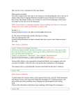
1
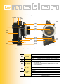
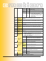
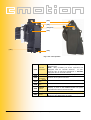
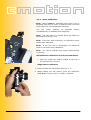
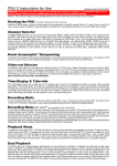
LENS CONTROL SYSTEM
USER GUIDE
st
as of April 21 2006 - technical specifications are subject to change without notice
by Lisa Buschek
User Guide Vers. 06-04
Introduction: Using The User’s Manual
Note: Notes are used to indicate important information for the user that
pertains to the respective section of this user’s guide.
Warning: Warnings are used to indicate important information for the user that
pertains to the respective section of this user’s guide and where something could
go wrong in the process or damage to units could be caused.
camin, coperate, czoom:
All cmotion components are written in cursive
throughout this user’s manual. These words can all also be found at the back of
this user’s manual.
Cables
When a cable is referred to in this user’s manual it will be referred to as follows
(e.g. FI 12p, LE 7p). Cables are referred to in reference to their connectors.
Cmotion cables are manufactured by W. W. Fisher, Lemo or Hirose which will be
referred to as FI, LE and HI respectively. The cable identification begins with the
connector that is connected to the cmotion unit, a comma follows, followed by
the connector which is connected to non-cmotion units; each connector takes
reference to the number of pins it has e.g. the cable (FI 12p, LE 7p) cable is the
cmotion Scorpio motor cable. The FI 7p connector is connected to the camin and
the LE 12p connector is connected to the Scorpio motor. Cables may also be
referred to by their commonly used names e.g. CBUS (FI 7p, FI 7p) and RS (FI
3p, FI 3p) cables, the cable for the CBUS interface and the cable for the RS
interface, respectively.
Necessary Tools
The following tools may be required to complete steps laid out in this user’s
manual:
4mm Allen key
Table of contents
1
2
SAFETY WARNINGS................................................................................... 4
COMPONENT DESCRIPTIONS .................................................................... 5
2.1
Component Overview ............................................................................ 5
2.2
Cmotion Software................................................................................. 8
2.3
Cmotion Accessories ............................................................................11
2.4
Spare Parts.........................................................................................15
2.5
Detailed Component Description............................................................16
2.5.1
camin.............................................................................................16
2.5.2
coperate .........................................................................................18
2.5.3
czoom ............................................................................................23
2.5.4
chandle ..........................................................................................25
2.5.5
cdisplay ..........................................................................................26
3
SYSTEM SET UP ....................................................................................... 29
3.1
camin ................................................................................................29
3.2
coperate............................................................................................33
3.3
czoom ...............................................................................................36
3.3.1
czoom and coperate .........................................................................36
3.3.2
czoom and chandle ..........................................................................36
3.3.2.1
Attaching the czoom/ chandle to the pan-bar...................................36
3.3.3
Various connections of czoom/chandle................................................37
3.3.3.1
czoom directly to the camin...........................................................37
3.3.3.2
czoom to the coperate ..................................................................38
3.3.4
czoom Stand Alone ..........................................................................38
3.3.5
Powering up the czoom ....................................................................38
3.4
cdisplay..............................................................................................40
3.4.1
cdisplay in Hard–wired Mode .............................................................40
3.4.2
cdisplay in Wireless Mode on the coperate ..........................................40
3.4.2.1
Releasing the cdisplay from the clamp ............................................41
3.4.3
cdisplay in Wireless-Mode in Stand Alone............................................41
Battery .......................................................................................................42
4
SYSTEM OPERATION ............................................................................... 43
4.1
camin ................................................................................................43
4.1.1
Turning the camin “ON” ....................................................................43
4.1.2
Channel Selection ............................................................................43
4.1.3
Changing Motor Direction..................................................................44
4.2
coperate.............................................................................................45
4.2.1
Channel Selection ............................................................................45
4.2.2
Turning the coperate “ON” ................................................................45
4.2.3
Motor Calibration .............................................................................46
4.2.4
Focus Pulling ...................................................................................47
4.2.5
Limit Setting ...................................................................................47
4.2.6
Locking the Knob .............................................................................51
4.2.7
The Marker Ring ..............................................................................51
4.2.8
Iris Control .....................................................................................52
4.2.9
Setting Motor Limits for the Slider......................................................52
4.2.10
Locking the Slider ........................................................................53
4.2.11
Marker Strips...............................................................................53
4.2.12
Camera Run ................................................................................53
4.2.13
Marker Button .............................................................................54
4.2.14
Battery Control ............................................................................54
4.2.15
Battery Charging..........................................................................54
4.3
czoom ................................................................................................55
4.3.1
Zooming .........................................................................................55
4.3.2
Zoom Speed ...................................................................................55
4.3.3
Setting Zoom Limits .........................................................................55
4.3.4
ZAP – Zoom as Fast as Possible.........................................................56
4.3.5
Camera Run ....................................................................................56
4.4
chandle .............................................................................................57
4.4.1
Motor Calibration .............................................................................57
4.4.2
Camera Run ....................................................................................58
1 SAFETY WARNINGS
Warnings
Notice:
Danger of operational error!
Danger of injury!
Damage to equipment possible!
General Safety Specifications
• Do not put your fingers near the motors while motors are
moving!
• In order to ensure optimal performance, read this Users’
Guide!
• Assembly and initial operation should be carried out only by
persons who are familiar with the equipment!
• Make sure all components (camin, Lens Motors, etc.) are
securely mounted!
• Remove batteries from components before transporting or
putting in storage!
• Repairs should be made only by authorized service centers!
• Use only original cmotion replacement parts!
• In the case of wet weather, routine safety precautions for
handling electrical equipment in wet weather should be taken!
• Do not remove any screws that are secured with paint!
• Do not remove warranty seal!
Important
If you have questions, or you need to order parts, please note
the component’s model and serial number.
Chapter 1 Safety Warnings
06-04
4/62
2 COMPONENT DESCRIPTIONS
2.1 Component Overview
This section will give you a brief description of all cmotion
components.
camin (Fig. 2. 1)
Fig. 2. 1: camin
The camin is the “brain” of the system. It communicates with the
camera and the lens motors. It can be connected to the other
components of the cmotion Lens Control System wireless or via
cable. Up to 3 lens motors can be plugged into the camin.
Commonly used digital servo motors from different manufacturers
(Arri, Preston, Scorpio, Hedén) can be connected to the camin. It
comes equipped with a radio/wireless module.
coperate (Fig. 2. 2)
The coperate is the hand-held unit of the cmotion Lens Control
System. It controls focus and iris. The coperate is equipped with a
control wheel and a control slider. The coperate is the main
cmotion hand unit. The system can be expanded in several ways
to a multi-functional 3 motor and camera control system. The
coperate user’s structure is clearly and comprehensively laid out,
with a user friendly design. The coperate is light-weight and its
design is based on stringent ergonomic principles.
Fig. 2. 2: coperate
czoom (Fig. 2. 3)
The czoom is an extension module of the cmotion Lens Control
System. It controls the zoom-motor. There are several ways to
integrate the czoom in the cmotion Lens Control System. It can
be attached directly to the coperate. It can be used in standalone mode, when used in combination with the chandle. The
czoom + chandle configuration can be hard-wired to either the
camin or the coperate.
Fig. 2. 3: czoom
Chapter 2 Component Descriptions
06-04
5/62
chandle (Fig. 2. 4)
The chandle is the handle unit for the czoom. It includes a [CAL]
and a [RUN] button. It enables the user to use the czoom in
stand-alone mode. The chandle is available in different wood
types, colors and styles.
Fig. 2. 4: chandle
cdisplay (Fig. 2. 5)
The cdisplay is a multi-functional display and control unit with a
3,8“ TFT-screen. The display has an integrated touch-screen. It
acts as a control unit for both lenses and cameras. The cdisplay
can be used stand-alone (in both wired and wireless
configurations), or can be connected directly to the camin. By
means of the cmotion fastening tool, the clamp, it can also be
connected directly to the coperate. Lens data can be stored in the
cdisplay.
Fig. 2. 5: cdisplay
cdisplay.ext (Fig. 2. 6)
The cdisplay-ext is an add-on module for the cdisplay. It allows for
wireless use of the cdisplay. Its package consists of: a reader
module for reading and writing the ctag (C017-K01) and a radio
module for independent communication with the camin.
Fig. 2. 6: cdisplay.ext
Chapter 2 Component Descriptions
06-04
6/62
ctag (Fig. 2. 7)
The ctag is the cmotion lens memory chip. All lens data is “read”
onto the ctag which then accompanies its respective lens. Anytime
the user may then need to upload lens information he/ she can
“read” the data onto the cdisplay and within seconds the lens data
is available on the cdisplay.
Note: Includes credit for lens calibration.
Fig. 2. 7: ctag
Chapter 2 Component Descriptions
06-04
7/62
2.2 Cmotion Software
clensinfo (Fig. 2. 8)
clensinfo is the software module for the cdisplay that allows for
lens and camera information to be displayed on the cdisplay
screen. The software reads out an animated depiction of the actual
lens barrel and its movements. On the focus scale the hyperfocal
distance is indicated with an “H” as well as focus near and focus
far of the depth of field. The user can also make focus marker
points on the focus scale using the coperate. The system is
compatible with all lenses and all camera systems which means
that all lenses can be depicted.
Fig. 2. 8: clensinfo
cfocas (Fig. 2. 9)
cfocas depicts a large scale image of the focus scale and all depth
of field information. The large fonts of the information make the
cfocas software practical and easy to use and practical.
Information that is read out onto the cfocas screen include: focus
near, focus far and distance measurement tools information. The
focus value fields indicate whether the current focus value is
within the depth of field according to color. Focus markers can
also be made on the focus scale. The software is compatible with
distance measurement tools e.g. the cinetape or. cfocas will
calculate the focus measurements using the distance information
provided by the cinetape or cfinder. The software is compatible
with all lenses and all camera systems.
Fig. 2. 9: cdepth
Chapter 2 Component Descriptions
06-04
8/62
camcon (Fig. 2. 10)
The camera control software allows the user to set camera
parameters such as fps and shutter.
Note: Currently, Arri 435, Arri 535, Arri 16SR3, Arri 35 III, Aaton
35 III, Aaton XTR Prod and the Panavision Millennium can be
controlled. Implementation of other cameras is in development.
Note: Please contact cmotion for the most recent camera control
information.
Fig. 2. 10: camcon
cramp (Fig. 2. 11)
The cmotion ramp software allows the user to program and
execute ramps.
Speed and depth of field ramps can be
programmed. Speed ramps can be compensated by the iris or
shutter or a mixture of both. The ramp time can be given in either
screen-time or ramp-time.
Note: Currently, Arri 435, Arri 535, Arri 16SR3, Arri 35 III, Aaton
35 III, Aaton XTR Prod and the Panavision Millennium can be
controlled. Implementation of other cameras is in development.
Note: Please contact cmotion for the most recent camera control
information.
Fig. 2. 11: cramp
Chapter 2 Component Descriptions
06-04
9/62
cdiscal (Fig. 2. 12 and Fig. 2. 13)
cmotion offers its users two calibration software interfaces; one
which is administered from a PC, and another which is
administered directly from the cdisplay. cdiscal is the cmotion
cdisplay lens calibration software. The software allows the user
to:
•
•
•
•
•
Fig. 2. 12: cdiscal- Welcome Screen
calibrate new lenses into the system,
edit existing lenses
delete existing lenses
register lenses to the system and
write lenses to ctags
Lens calibration memorizes motor positions in relation to the user
entered lens scales and the end-stops. This must be completed
once for each lens and can be done using the cdiscal interface.
Fig. 2. 13: cdiscal - Iris Calibration
Screen
Chapter 2 Component Descriptions
06-04
10/62
2.3 Cmotion Accessories
clamp (Fig. 2. 14)
The clamp allows the user a very comfortable use of the coperate
and the cdisplay together. The clamp provides mechanical and
internal electronic connection between coperate and cdisplay.
Fig. 2. 14: clamp
Battery (Fig. 2. 15)
Battery, 2.400mAh, 7.2V for all cmotion hand-units
Fig. 2. 15: Battery
Battery Charger (Fig. 2. 16)
Battery charger for cmotion batteries, includes 3 batteries
Fig. 2. 16: Battery Charger
Socket Adapter (Fig. 2. 17)
Worldwide socket adapter
Fig. 2. 17: Worldwide Socket
Adapter
Chapter 2 Component Descriptions
06-04
11/62
ctruss (Fig. 2. 18)
The ctruss is a coperate fastening tool. It is attached to the back
of the coperate giving the user access to a multi-functional 1/4
inch screw hole. The ctruss allows the cstrap can be screwed to
the back of the coperate.
Fig. 2. 18: ctruss
cstrap (Fig. 2. 19)
Universal carry-strap accompanied with a 1/4 inch screw. It
includes an innovative locking mechanism to prevent it from
coming loose.
Fig. 2. 19: cstrap
cboost (Fig. 2. 20)
Fig. 2. 20: cboost
Adapter for power supply cables that keeps the voltage at a
steady 28 V. The entry voltage can be anywhere between 10V
and 35V. The cboost is used with 10V camera systems to boost
the voltage available to lens motors.
cfastener (Fig. 2. 21)
The cfastener is a universal clamp to be secured to rods 15-28mm
(e.g. a support rod or the pan-bar). The clamp comes with two
1/4 inch screws to allow attachment of various fixtures.
Fig. 2. 21: cfastener
Chapter 2 Component Descriptions
06-04
12/62
cfast-czoom (Fig. 2. 23)
Attachment set that attaches the czoom to the pan-bar or directly
to the camera. The rosette is the same size as an Arri rosette, and
is two-sided allowing for attachment to both sides.
Fig. 2. 22: cfast-czoom
cfast-camin (Fig. 2. 23)
Attachment set which secures the camin to the camera or any
1/4” or 3/8” screw hole. A 6 sided piece is attached to the camin
which slips into the cfast-camin receiver. An integrated quick lock
allows for quick and easy mounting and dismounting of the camin.
Fig. 2. 23: cfast-camin
cfast-cdisplay (Fig. 2. 24)
Attachment set that connects the cdisplay to the camera. The
multifunctional arm allows for optimal positioning of the cdisplay.
Fig. 2. 24: cfast-cdisplay
cfast-artemis (Fig. 2. 25)
Attachment tool that secures the camin to the Sachtler-Artemis
Steadycam system.
Fig. 2. 25: cfast-artemis
Chapter 2 Component Descriptions
06-04
13/62
Calibration Package (Fig. 2. 26)
The calibrating package includes all necessary tools for lens
calibration with a PC. The set includes: software, webcam,
fastening tool for the webcam, 2 rods, power supply, lens mount.
Note: DOES NOT INCLUDE: Laptop, lens, camin or lens-motor
Calibration Software
Fig. 2. 26: Calibration Package,
includes calibration software
The cmotion calibration software is a PC program that allows the
user to implement new lenses into the system. Cmotion also offers
a calibration software which is administered directly through the
cdisplay called cdiscal.
Chapter 2 Component Descriptions
06-04
14/62
2.4 Spare Parts
Antenna (Fig. 2. 27)
Flexible swivel antenna, straight or right angle, length 10cm,
+1dBi, 2.4Ghz, for all units
Fig. 2. 27: Antenna
Marker Ring (Fig. 2. 28)
Marker ring for rotary knob, for coperate and Arri WFU.
Fig. 2. 28:
Marker Ring
Marker Strip (Fig. 2. 29)
Marker strip for slider, for coperate
Fig. 2. 29: Marker Strip
Chapter 2 Component Descriptions
06-04
15/62
2.5 Detailed Component Description
2.5.1
camin
Connectors and LEDs on the camin CHANNEL side
C1
Channel
Selector
[C2]
[C1]
[C3]
C2
[C5]
Antenna
Connector
[C4]
[C6]
Selector knob for radio transmission
Depending where the device is used, select the
channel accordingly
Set l1l – l7l in Europe, USA and Canada
Set l8l – l9l in Europe, USA, Canada and Japan and
Australia
Set l0l to switch off the transceiver, or to use in hand
wired mode.
Flexible swivel antenna, straight or right angle,
attached here
RF
ON
Off
Off
camin off
camin ready, (hardwired mode –
Red/
Off
Green/ channel selector set at 0), no client
Blinking logged on
Red
Red/
camin ready (wireless mode), no
Blinkin Green/
client logged on
g
Blinking
[C7]
[C8]
Off
[C9]
camin ready, client logged on in
hard-wired mode
•
During Start-Up: motor is
moving to position that hand
units are currently set at
camin ready, client logged on in
wireless mode
•
During Start-Up: camin is
booting up
•
Selected channel already in use
by another camin
•
Channel selector dial was turned
during operation
•
Green
RF LED/ ON
C3/ LED
C5
(Operation
Status)
Green Green
Fig. 2. 30: The camin Channel Side
Red
Red
Green
Software incompatible between
Red
Blinkin
Blinking camin and clients
g
Red
Red
Battery low, camin will not work
Blinking
C4
C6
C7
C8
C9
camin
ON/OFF
Switch
16 Pin EXT
Connector
M4
Screw
Hole
CBUS
Connector
RS
Connector
camin power switch
Connector for camera communication,
synchronizations and power supply.
For attachment of various accessories
Cmotion intra-system 7 pin connector
Camera power supply connector
Chapter 2 Component Descriptions
06-04
16/62
Connectors and LEDs on the camin MOTOR side
M1
Focus LED
[M1]
[M2]
[M3]
M2
[M4]
[M5]
M3
[M6]
M4
[M7]
Focus
Motor
Connector
Focus
Motor
Direction
Switch
Iris LED
[M8]
[M9]
M5
Fig. 2. 31: The camin Motor Side
M6
M7
M8
M9
Iris Motor
Connector
Iris Motor
Direction
Switch
Zoom
LED
Zoom
Motor
Connector
Zoom
Motor
Direction
Switch
Green
Green/
Red
Blinking
Off
Focus motor ready
•
System is calibrating or
•
the focus motor cannot reach its
position
No motor connected
Connector for digital servo motors for focus
Changes direction of the focus motor between
clockwise and counterclockwise
Green
Green/
Red
Blinking
Off
Iris motor ready
•
System is calibrating or
•
the iris motor cannot reach its
position
No motor connected
Connector for digital servo motors for iris
Changes direction of the iris motor between
clockwise and counterclockwise
Green
Green/
Red
Blinking
Off
Zoom motor ready
•
System is calibrating or
•
the zoom motor cannot reach its
position
No motor connected
Connector for digital servo motors for zoom
Changes direction of the zoom motor between
clockwise and counterclockwise
Chapter 2 Component Descriptions
06-04
17/62
2.5.2
[O1][O2]
coperate
[O3] [O5]
[O4]
[O24]
[O6]
[O7]
[O9]
[O8]
[O12]
[O10]
[O10]
[O13]
[O18]
[O6]
[O19]
[O20]
[O15]
[O22]
[O21]
[O14]
[O23]
[O16]
[O25]
[O17]
Fig. 2. 32: The coporate top view and right side
O1
O2
RUN LED
RUN Button
•
•
Green
Camera running
Red
Camera error or camera is running up/ down
Starts/ stops camera
•
O3
O4
O5
CAL Button
CAL LED
RDY LED/
RF LED
No RUN signal received from camera or
Camera in standby mode
Off
•
Button to start motor calibration (Push for at least
one second) or
can be used together with a LENS Button for single
motor calibration
Off
Lens has been calibrated
Yellow
Motors are calibrating
Yellow
Blinking
Motor(s) need to be calibrated
RDY
RF
Off
Off
System off
Green
Off
System ready, client logged on in
hard-wired mode
Chapter 2 Component Descriptions
06-04
18/62
Green
Green
System ready, client logged on in
wireless mode
Green
Red
Radio transmission has minor errors
Red
Blinking
--
Battery is going to be empty
•
Red
Red
•
•
O6
O7
Mechanical
End-Stop
Lock
Exchangeabl
e Markable
Ring
coperate error, system will only
work in hard-wired mode
No radio transmission to camin,
system will only work in hardwired mode
Battery empty
Enables you to set mechanical limits on the wheel
rotation
Can be used to write (e.g. focus marks) on the ring
O8
Knob
Depending on the position of the Iris/ Focus Selector
the hand wheel knob will control either the Focus or the
Iris motor
O9
Slider Lock
Locks the slider as well and adjusts slider resistance
O10
Exchangeabl
e Marker
Strip
Can be used to write (e.g. a Iris scale) on the pad
O11
Knob Lock
Locks the knob rotation
O12
Index
Marker
O13
Slider
O14
LENS Button
(Slider)
Enables a precise reading of the inscriptions written on
the ring
Depending on the position of the Iris/ Focus Selector
the slider will control either the Iris or the Focus motor
•
Assigns a segment of the lens scale to the entire
length of the slider or
•
can be used together with the [CAL] button for
single motor calibration
Off
Green
O15
LENS LED
(Slider)
Red
Green
Blinking
O16
Iris / Focus
Selector
Pos. 1
(Up)
Pos. 2
(Down)
Off
O17
BAT LED
Red
Slowly
Blinking
Red Fast
Blinking
Red
O18
OPEN IRIS
Motor ready for control
Limits have been set by the LENS button
• No motor available or
• another unit is in control of the motor
Limits are currently being set, LENS button
is currently being pushed
Slider will control the Iris
Knob will control the Focus
Slider will control the Focus
Knob will control the Iris
coperate battery is OK
coperate battery is running low
coperate battery is almost empty, CHANGE
BATTERY
coperate battery is empty, CHANGE
BATTERY
Opens the aperture completely
Chapter 2 Component Descriptions
06-04
19/62
button
O19
KNOB LED
O20
KNOB
button
O21
LENS Button
(Knob)
Note: If aperture closes, change the motor direction of
the IRIS motor with the DIR switch on the camin
Off
No limits have been assigned to the wheel
Green
Limits have been set by the KNOB button
Limits are currently being set, KNOB button
Green
Blinking
is currently being pushed
Assigns a rotation of the lens scale, e.g. from close
focus to infinity, to just one segment of the wheel
rotation
•
Assigns a segment of the lens scale to the entire
rotation of the slider or
•
can be used together with the [CAL] button for
single motor calibration
Off
Motor is ready for control
Limits have been set by the LENS button
(Knob)
• No motor available or
Red
• another unit is in control of the motor
Limits are currently being set, LENS button
Green
Blinking
(Knob) is currently being pushed
While holding the coperate vertically, press the release
button to enable the battery to glide out of its
receptacle.
Green
O22
LENS LED
(Knob)
O23
Battery
Release
Button
Chapter 2 Component Descriptions
06-04
20/62
[O24]
[O26]
[O27][O28]
[O29]
[O31]
[O30]
Fig. 2. 33: The coperate
Antenna
O24 Connector
O25 RF LED
CBUS
O26 Connector
¼” Screw
O27 Hole
¼” Screw
O28 Hole
MARKER
O29 button
Flexible swivel antenna, straight or right angle,
attached here
Note: Only necessary for those coperates not
equipped with an internal antenna.
If your
coperate has an antenna attachment it IS NOT
equipped with an internal antenna
shows if there is radio contact (see [05])
cmotion intra-system interface
For attachment of various accessories
For attachment of various accessories
When the coperate is configured to work with the
cdisplay, a push on the MARKER button will place
a numbered mark on the Focus scale
O30 Battery receptacle
An accessory to be attached to the coperate,
O31 ctruss
allows for the attachment of cstrap
Chapter 2 Component Descriptions
06-04
21/62
[O24]
[O32]
[O27]
[O27]
[O33]
[O31]
Fig. 2. 34: The coperate
O24
Antenna
Connector
Flexible swivel antenna, straight or right angle,
attached here
Note:
Only necessary for those coperates not
equipped with an internal antenna. If your coperate
has an antenna attachment it IS NOT equipped with
an internal antenna
O27
CBUS
Connector
cmotion intra-system interface
O31
BATTERY receptacle
O32
ON Button
O33
CHANNEL
selector
coperate power button
Note: Must be pushed for at least ½ second
Note: If the camin is turned off the coperate will
turn off automatically
Note: If communication can not be formed the
coperate will turn off automatically
Selector knob for radio transmission
Note: Select the same radio channel as set on the
camin
Chapter 2 Component Descriptions
06-04
22/62
2.5.3
czoom
[Z3]
[Z1]
[Z5]
[Z4]
[Z6]
[Z10]
[Z2]
[Z7]
[Z8]
[Z3]
[Z9]
Fig. 2. 35: The czoom
Z1
SPEED Dial
Z2
LENS Button
Z3
LENS LED
Sets/presets the speed of the zoom motor, 1-9,
1=slow 9=zoom as fast as possible
•
Assigns a segment of the zoom lens scale to the
force sensitive joystick or
•
can be used together with the [CAL] button for
single zoom motor calibration
Off
No limits have been set
Green
Limit has been set
Green
Slowly
Blinking
Green
Fast
Blinking
Red
Zoom
Control
Z6
CAL Button
RDY LED
Motor error
Motor is currently being calibrated
Force sensitive joystick to control the zoom motor
•
Z5
• Limits are currently being set
• LENS button is currently being pushed
Czoom is not in control of the motor
Red
Blinking
Red/
Green
Blinking
Z4
Motor is at end-stop
•
Button to start motor calibration (Push for at
least one second) or
can be used together with a LENS Button for
single motor calibration
Off
czoom has no power
Green
System is ready
Red/
Green
Blinking
Searching for camin
Red
Error has occurred (e.g. another unit is
in control of the motor. System is not
ready)
Chapter 2 Component Descriptions
06-04
23/62
Z5/
Z6
LENS
LED/
RDY LED
Z7
czoom
Connector
Z8
ZAP Button
Z9
Mounting
Screw
Z10
CBUS
Connector
LENS
RDY
Green
Software incompatible
Red Blinking
Blinking
with camin
Used to connect the czoom to the coperate or the
chandle. (CBUS female connector)
While performing zoom control, moves motor as
fast as possible (Zoom As Fast as Possible)
By means of an M4 Allen key, tighten the screw to
fix the czoom either on the coperate or on the
chandle
Cmotion intra-system interface
Chapter 2 Component Descriptions
06-04
24/62
2.5.4
chandle
[H5]
[H1] [H2]
[H3]
[H4]
[H6]
Fig. 2. 36: The chandle
•
Off
H1
H2
H3
RUN LED
RUN Button
CAL LED
H4
CAL Button
H5
3/8”
Hole
H6
CBUS
Connector
(front)
Screw
•
No RUN signal received from camera
or
Camera in standby mode
Green
Camera running
Red
Camera error or camera is running up/
down
Starts/ stops camera
Off
Lens has been calibrated
Yellow
Motors are calibrating
Yellow
Motor(s) need to be calibrated
Blinking
•
Button to start motor calibration (Push for at
least one second) or
•
can be used together with a LENS Button for
single motor calibration
For attachment of cfast-cdisplay
cmotion intra-system interface
Chapter 2 Component Descriptions
06-04
25/62
2.5.5
cdisplay
[D2]
[D1]
[D3]
[D4]
[D5]
[D6]
[D11]
[D7]
[D8]
[D9]
[D10]
[D12]
[D13]
Fig. 2. 37: The cdisplay
D1
D2
Antenna
Connector
STANDBY
Button
Flexible swivel antenna, straight or right angle, attached
here
cdisplay power button
ON LED
RF LED
Off
D3/
D4
D5
D6
ON LED/
RF LED
cdisplay.ext
Display With
Red
--
Red
Blinking
Green
Green
Blinking
--
Red
Blinking
Green
Red
Red
Red
Blinking
Off
cdisplay off or in standby mode
During Start-Up: System is not yet
ready or
cdisplay cannot find communication
with other unit or
battery empty
System is searching for connection
Normal wireless operation
--
cdisplay is reading transponder
Off
Unit is in hard-wired mode
Channel is currently being changed or
no RF connection
Battery critically low
cmotion wireless extension module
• cdisplay screen
Chapter 2 Component Descriptions
06-04
26/62
D7
D8
D9
D10
D11
D12
D13
Touch
• Used for operation of cdisplay programs
Screen
Battery Receptacle
Menu Arrow
Buttons
Used to navigate through the cdisplay menu
Menu
ENTER
Button
MENU
Button
READ
Button
Battery
Release
Button
CBUS
Connector
Used to make selections in the cdisplay menu
Uploads cdisplay main menu
Used to transfer data to and from the ctag
While holding the cdisplay vertically, press the release
button to enable the battery to glide out of its receptacle
cmotion intra-system 7 pin connector
Chapter 2 Component Descriptions
06-04
27/62
[D1]
[D13]
[D11]
[D15]
[D5]
[D5]
[D14]
[D16]
[D10]
Fig. 2. 38: The cdisplay-side view
D1
D5
D12
D13
D11
D14
Antenna
Connector
cdisplay.ext
Battery
Release Button
CBUS
Connector
READ Button
3/8”
Screw
Hole
D15
Channel
Selector
D16
3/8”
Hole
Screw
Flexible swivel antenna, straight or right angle,
attached here
cmotion wireless extension module
While holding the cdisplay vertically, press the
release button to enable the battery to glide out
of its receptacle
cmotion intra-system 7 pin connector
Used to transfer data to and from the ctag
For attachment of various accessories or cfastcdisplay
Selector knob for radio transmission
Note: Select the same radio channel as set on
the camin
For attachment of various accessories
Chapter 2 Component Descriptions
06-04
28/62
3 SYSTEM SET UP
This section will tell you how to set the cmotion system up. The
section will start with camin set up, and then it will move on to
coperate, czoom and cdisplay set up.
3.1 camin
Fig. 3. 1
Fig. 3. 2
The camin is the “brain” of the cmotion Lens Control System. It
allows for communication between the lens motors and all
cmotion control units. You will have to secure the camin
somewhere near the camera (see Fig. 3. 1), attach motor cables
and facilitate communication between units.
1. Mount Lens Motors and camin securely to camera, the camin
can be attached to the camera using the attachment tool,
cfast-camin (see Fig. 3. 2) or the cfast-camin & cfastener
(see Fig. 3. 4).
Note: The cfastener can be attached to rods 15-28mm in
diameter e.g. camera carrying handles. The cfast-camin
consists of a six-sided insert piece (located on the camin)
and an interlocking mechanism with a steel release clip
(located on the camera or the cfastener, see Fig. 3. 2).
To attach the cfast-camin:
Fig. 3. 3
i. Using a 4mm Allan key attach the six-sided insert piece
to the camin
ii. Using a 4mm Allan key attach the cfast-camin to any
3/8” or 1/4” screw hole (e.g. the camera carrying handle)
or to the cfastener
iii. Attach the cfastener to any rod 15-28 mm (see Fig. 3.
4). Fasten securely!
Fig. 3. 4
iv. Place the insert piece into the interlocking mechanism at
an angle (see Fig. 3. 3)
v. Gently move the insert piece into the interlocking
mechanism until you hear an audible click
To release the cfast-camin:
i. Pull the steel release clip towards the camin
ii. Tilt the insert piece out of the interlocking mechanism
while still pulling the release clip
Fig. 3. 5
Chapter 3 System Set Up
06-04
29/62
2. Use the cable RRS-x (FI 3p, FI 3p) to connect the camin to
the camera (see Fig. 3. 6).
Note: RRS-x is for various Arri cameras. See attachment
for more cameras
3. Screw on the antenna
4. Connect Lens Motors to the camin
Fig. 3. 6
•
ARRI CLM-1: with RLM-1 (FI 7 p, FI 5p) cable to
CBUS Connector (blue). The original cable can be
used as a connection to the Arri CLM-1 motor.
•
ARRI CLM-2: directly with the integrations cable
(FI 12p) to the Focus, Iris and Zoom connectors
(green)
•
Denz: directly with the integrations cable (FI 12p)
to the Focus, Iris and Zoom connectors (green)
•
Hedén M26VE: with RHM-x (FI 12p, LE 7p) cable
to the Focus, Iris and Zoom connectors (green)
Note: When using the Hedén motors (see Fig. 3. 7)
included in cmotion sets), the gear rings can be easily
exchanged (see Fig. 3. 8) according to teeth size. They
can also be placed on either side of the motor. The
following moduls are available:
Fig. 3. 7
i. Push on the small rod exiting the opposite side of
the gear ring mount.
ii. Choose the gear ring with your desired teeth size
iii. Choose the side on which you would like to gear
ring to be placed
iv. Place gear ring rod into hole located on the gear
ring mount
v. Gently push gear ring while slowly turning it until
rod pops into hole
Fig. 3. 8
vi. Push rod completely into hole until it clicks
The rod attachment ring’s height can also be adjusted to
assure that the motor can reach the lens gear ring.
Chapter 3 System Set Up
06-04
30/62
• Preston: with RPM -1 (FI 12p, LE 7p) cable to the Focus,
Iris and Zoom connectors (green)
• Scorpio: with RSM-1 (FI 12p, LE 7p) cable to the Focus,
Iris and Zoom connectors (green)
Warning: Make sure that the cables will not get in the
way of equipment, during operation, or during camera
handling (movement).
5. Select a radio channel
CHANNEL
Region
0
OFF
1
Europe/USA/Canada
2
Europe/USA/Canada
3
Europe/USA/Canada
4
Europe/USA/Canada
5
Europe/USA/Canada
6
Europe/USA/Canada
7
Europe/USA/Canada
8
Europe/USA/Canada/Japan/Australia
9
Europe/USA/Canada/Japan/Australia
6. Switch camin ON.
7. Check LEDs
RF
Off
ON
Off
Red/
Off
Green/
Blinking
Red/
LED/ Red
Green/
LED Blinking
Blinking
RF
ON
(Operation
Status)
camin off
camin ready, (hardwired mode – channel
selector set at 0), no client logged on
camin ready (wireless mode), no
logged on
client
camin ready, client logged on in hardwired mode
•
During Start-Up: motor is moving to
position that hand units are currently set
at
camin ready, client logged on in wireless
mode
•
Off
Green
Green
Green
RF
LED/ RF
ON LED
(Warnings)
Red
ON
•
•
Red
•
Chapter 3 System Set Up
During Start-Up: camin is booting up
Selected channel already in use by
another camin
Channel selector dial was turned during
operation
06-04
31/62
Green
Red
Software incompatible between camin and
Blinking Blinking clients
Red
Red
Battery low, camin will not work
Blinking
Green
Focus motor ready
Green/
•
System is calibrating or
Focus LED Red
•
the focus motor cannot reach its position
Blinking
Off
No motor connected
Green
Iris motor ready
Green/ •
System is calibrating or
Iris LED
Red
•
the iris motor cannot reach its position
Blinking
Off
No motor connected
Green
Zoom motor ready
Green/ •
System is calibrating or
Zoom LED Red
•
the zoom motor cannot reach its position
Blinking
Off
No motor connected
Warning: Important information for using the LCS system
with the Titan Transvideo(TM)
Cmotion channels 8 and 9 should be used while operating
wireless video link. Channel A should be used on the
Transvideo.
The camin and the Transvideo transmitter Tx should be placed
as far away as possible from each other.
The antennas should be aligned parallel to each other (they
should not cross)
Chapter 3 System Set Up
06-04
32/62
3.2
coperate
The coperate is the hand control unit of the cmotion system (see
Fig. 3. 9). Please follow the following steps to get it ready for
operation.
Note: coperate set-up is to be done after camin set-up.
Note: If the slider and/ or knob do not move; loosen their
respective locks
1. Screw on the
necessary).
Fig. 3. 9
antenna
(If
external
antenna
is
Note: If you have a coperate with an antenna connector
then an external antenna is necessary. If no antenna
connector is available, your system is accompanied with an
internal antenna.
Note: You can also use the coperate in hard-wired
mode. You can connect the coperate and the camin using
the CBUS cable (FI 7p, FI 7p). As soon as the CBUS cable
(FI 7p, FI 7p) is connected the system’s wireless mode will
turn off automatically.
2. Insert a battery. Press until it snaps in with an
audible click.
Note: If you use the coperate hardwired no battery is
necessary.
Removing an Empty Battery:
Fig. 3. 10
i. Hold the coperate wheel with your right hand, so that
the opening of the battery receptacle looks
downwards.
ii. Press the release button (see Fig. 3. 10) with your
left index finger. The battery will slide out into your
hand. (see Fig. 3. 11)
Fig. 3. 11
Chapter 3 System Set Up
06-04
33/62
3. Preset the same radio channel as selected on the
camin.
4. Push the [ON] button (see Fig. 3. 12), for at least half
a second, to turn the coperate “ON”.
Warning: If the coperate turns off automatically after 6
seconds it cannot establish communication with the camin.
Is the camin turned on? Are all units preset to the same
channel?
Fig. 3. 12
Note:
The coperate offers a Camera Run Toggle
Function for video cameras. Because the cmotion system
usually only reads out the Camera Run LED if the camera
delivers a status feedback and video cameras do not
deliver status information; the Camera Run Toggle function
allows you to have a camera run LED read-out once the
Camera Run Button has been activated without a status
feedback. The video camera must be connected with the
Video Camera Interface cable (FI 16p, HI 12p). To activate
the Camera Run Toggle function:
i. When turning the coperate on, hold down the Camera
Run Button
Note: Make sure that the knob mechanical locks on the
knob are located at their end-stops
Accessory: The cstrap
The cstrap is a universal carry-strap; when the coperate is
attached to the cstrap, the coperate can twist freely.
Screw the cstrap into the ¼ inch screw hole located at the
bottom of the Coperate as tight as you can.
To Secure the Screw:
Push and turn the screw head to the right to fix the cstrap
(see Fig. 3. 13)
Note: The key ring is meant to act as a lever to help you
turn and secure the screw
Note: The screw will not seem to move much while
securing
5. Check LEDs
Fig. 3. 13
•
Off
•
RUN LED
No RUN signal received from
camera or
Camera in standby mode
Green
Camera running
Red
Camera error or camera is running up/
down (this warning signal depend on
the function of the camera)
Chapter 3 System Set Up
06-04
34/62
CAL LED
RDY
LED/ RF
LED
Off
Lens has been calibrated
Yellow
Motors are calibrating
Yellow Blinking
Motor(s) need to be calibrated
RDY
RF
Off
Off
Green
Off
Green
Green
Green
Red
Green
Blinking
Off
Red
Blinking
--
System off
System ready, client logged on in
hard-wired mode
System ready, client logged on in
wireless mode
Radio transmission has minor errors,
system will continue operation
During Start-Up: motor is moving to
position that hand units are currently
set at
Battery empty
•
Red
Red
•
•
LENS
LED
(Slider)
Off
Motor ready for control
Green
Limits have been set by the LENS
button
• No motor available or
• another unit is in control of the
motor
Limits are currently being set, LENS
button is currently being pushed
No limits have been assigned to the
wheel
Limits have been set by the KNOB
button
Limits are currently being set, KNOB
button is currently being pushed
coperate battery is OK
Red
Green Blinking
Off
KNOB
LED
Green
Green Blinking
Off
BAT LED
Red Slowly
Blinking
Red Fast
Blinking
Red
Off
Green
LENS
LED
(Knob)
coperate error, system will only
work in hard-wired mode
No radio transmission to camin,
system will only work in hardwired mode
Battery empty
Red
Green Blinking
Chapter 3 System Set Up
coperate battery is running low
coperate battery is almost empty,
CHANGE BATTERY
coperate battery is empty, CHANGE
BATTERY
Motor is ready for control
Limits have been set by the LENS
button (Knob)
• No motor available or
• another unit is in control of the
motor
Limits are currently being set, LENS
button (Knob) is currently being
pushed
06-04
35/62
czoom
3.3
The czoom (Fig. 3. 14) is the zoom control unit of the cmotion
Lens Control System. There are three ways to implement the
czoom into the cmotion Lens Control System.
Fig. 3. 14
•
On the coperate
•
On the chandle
•
Stand alone
Please complete the following steps:
3.3.1
czoom and coperate
Note: With the czoom attached to the coperate you can
control three motors wireless
You will find a CBUS connecter and a screw hole on the left
top of the coperate over the green RUN button.
1. Attach the czoom to the CBUS connector on the
coperate as seen in Fig. 3. 15
Fig. 3. 15
2. Using a 4mm Allan key, securely fasten the screw
located at the bottom of the czoom
3.3.2
czoom and chandle
Note: The chandle is the czoom hand grip. It has a [RUN]
and a [CAL] button. It can be attached via CBUS (FI 7p, FI
7p) to the coperate or directly to the camin
Fig. 3. 16
1. Plug the czoom to the CBUS connector on the chandle
(see Fig. 3. 16)
2. Using a 4mm Allan key, securely fasten the screw
located at the bottom of the czoom
3. Using the CBUS cable (FI 7 p, FI 7p), connect the
czoom- chandle to the camin (see Fig. 3. 17). It can
also be connected directly to the coperate (see Fig. 3.
17)
Fig. 3. 17
3.3.2.1 Attaching the czoom/ chandle to the pan-bar
Chapter 3 System Set Up
06-04
36/62
Using the cfastener-czoom (see Fig. 3. 18) the czoom can
be attached to the pan – bar allowing for practical zoom
control. The cfast-czoom is composed of an arm, two
rosettes and a cfastener. It can be attached to any rod
15-28 mm e.g. the pan bar. The angle of the czoom to the
pan-bar can also be adjusted with the cfast-czoom
providing optimal comfort for the user.
Fig. 3. 18
Note: The arm of the cfast-czoom has two rosettes. One
rosette is attached to the cfastener and the other is
attached to the czoom. The rosette that attaches to the
cfastener can be switched from side to side of the arm.
This means that the cfastener can be attached to the inside
or the outside of the czoom (see Fig. 3. 18).
1. Attach the czoom to the cfast-czoom using the
rosettes. Secure tightly with the tightening lever.
2. Attach the cfastener to the pan-bar (or any other rod
15-28 mm). Secure tightly with the tightening lever.
(see Fig. 3. 19)
Note: Adjusting the angle of the czoom to the panbar
Now you can adjust the angle of the czoom to the pan-bar
to ensure maximum comfort.
1. Loosen the tightening lever slightly
Fig. 3. 19
2. Rotate the czoom along the rosettes to your desired
angle.
3. Once you have established your desired position,
tighten the tightening lever again.
Note: The czoom can also be attached to the pan-bar with
the Oppenheimer adapter (See Fig. 3. 20).
Fig. 3. 20
3.3.3
Various connections of czoom/chandle
When the czoom is connected to the chandle it can be
operated in various configurations using the CBUS cable
(FI 7p, FI 7p)
3.3.3.1 czoom directly to the camin
Chapter 3 System Set Up
06-04
37/62
Using the CBUS cable (FI 7p, FI 7p) you can connect the
czoom directly to the camin e.g. the czoom is on the panbar and hardwired directly to the camin.
The
czoom/chandle can be attached to either side of the panbar.
3.3.3.2 czoom to the coperate
Using the CBUS cable (FI 7p, FI 7p) you can connect the
czoom to the coperate (see Fig. 3. 21) e.g. The czoom is
attached to the coperate using the CBUS (FI 7p, FI 7p) and
the second assistant is holding the czoom/ chandle in his
or her hand.
3.3.4
Fig. 3. 21
czoom Stand Alone
The czoom also functions without the chandle. The czoom
can be connected to the camin or the coperate using the
CBUS (FI 7p, FI 7p) cable e.g. steadicam operators.
3.3.5
Powering up the czoom
Note: The czoom does not have a power button!
The czoom will turn on automatically as soon as it has
been attached to the coperate or to a CBUS (FI 7p, FI 7p)
cable, as long as the camin and/or the coperate are turned
on.
Chapter 3 System Set Up
06-04
38/62
1. Check LEDs
RDY
LED
LENS
LED
Off
czoom has no power
Green
System is ready
Red/ Green Blinking
Searching for camin
Red
Error has occurred (e.g.
another unit is in control of the
motor. System is not ready)
Off
No limits have been set
Green
Limit has been set
Green Slowly Blinking
Motor is at end-stop
Green Fast Blinking
• Limits are currently being set
• LENS button is currently
being pushed
Czoom is not in control of the
motor
Red
LENS
LED/
RDY
LED
Red Blinking
Motor error
Red/ Green Blinking
Motor is currently being
calibrated
LENS
RDY
Green Blinking
Red Blinking
Chapter 3 System Set Up
Software incompatible
06-04
39/62
3.4 cdisplay
The cdisplay is a multi-functional monitor and control unit with a
3,8” TFT-screen (Fig. 3. 22). The cdisplay can be used in
wireless and hard – wired modes. There are three ways to
implement the cdisplay into the cmotion Lens Control System.
•
In hard-wired mode via the CBUS cable (FI 7p, FI 7p)
to the coperate or to the camin
•
In wireless mode on the coperate
•
Stand alone in wireless mode.
Fig. 3. 22
Please follow the following steps:
3.4.1
cdisplay in Hard–wired Mode
Attaching the cfast-cdisplay (see Fig. 3. 23) to the cdisplay
and to any 15-28mm rods e.g. lens motor rods
1. Screw the UNC 3/8” screw from the cfast-cdisplay
into the hole located at the bottom (or on the righthand side) of the cdisplay.
Fig. 3. 23
2. Attach the cfastener to any rod 15-28mm e.g. the
lens motor rods.
3. Adjust the angle of the cfast-cdisplay arm to your
desired position.
4. Tighten the lock knob to secure arm angle
Connecting the cdisplay to the camin
1. Connect the cdisplay to the camin using the CBUS
cable (FI 7p, FI 7p)
3.4.2
cdisplay in Wireless Mode on the coperate
If the cdisplay is attached to the coperate the user can
take advantage of all cdisplay programs as well as control
the lens motors all in one multi-functional unit (see Fig. 3.
24).
Fig. 3. 24
Note: In this configuration, there is no antenna necessary
for the cdisplay
Attaching the cdisplay to the coperate using the clamp
Chapter 3 System Set Up
06-04
40/62
Note: Attaching the clamp
You will find a CBUS connecter and a screw hole on the left
hand side of the coperate under the green RUN button.
1. Attach the clamp as seen in Fig. 3. 25
Fig. 3. 25
2. Stick your 4mm Allen Key in the screw hole and tighten
clamp as seen in Fig. 3. 26.
Fig. 3. 26
3. Slide cdisplay screen onto the silver mounting found on
the clamp (as seen in Fig. 3. 27) until you hear an
audible click.
3.4.2.1 Releasing the cdisplay from the clamp
i. Push the Battery Release Button located at the
bottom right hand side of display screen and
ii. Slide cdisplay off the quick clamp
Fig. 3. 27
3.4.3
cdisplay in Wireless-Mode in Stand Alone
The cdisplay can be used in wireless stand alone mode
(see Fig. 3. 28).
Note: In order for the cdisplay to be used in stand alone
wireless mode it must be equipped with the cdisplay.ext
(the cdisplay wireless extension module)
1. Screw on the antenna
2. The cdisplay can be used with the cfast-cdisplay or
can simply be held in the user’s hand.
3. Slide the battery on at the back of the cdisplay until
you hear an audible click
Fig. 3. 28
Chapter 3 System Set Up
06-04
41/62
Battery
If you are using the cdisplay in wireless stand alone mode
you will have attach a battery. The cdisplay necessitates
standard Canon batteries.
Removing an Empty Battery:
Note: The cdisplay battery release button is located on
the right hand side of the cdisplay.
iii. Hold the cdisplay so that the battery release button is
facing you
iv. Hold the battery in your hand
v. Press the release button and the battery will fall into
your hand.
Note: As soon as the cdisplay has a power source it will
turn on automatically
Note: The blue button located at the top right-hand side
of the cdisplay is only a stand-by button. To turn the
cdisplay off you must remove the battery, disconnect the
CBUS (FI 7p, FI 7p) cable or turn the camin or the
coperate off.
Note: In order to turn the cdisplay off you must either
remove the battery, disconnect the CBUS cable or
disconnect the cdisplay from the clamp.
Check LEDs
1. Check LEDs
ON LED
RF LED
Off
D3/
D4
ON LED/
RF LED
Red
--
Red
Blinking
Green
Green
Blinking
--
Red
Blinking
Green
Red
Red
Red
Blinking
Off
Chapter 3 System Set Up
cdisplay off or in standby mode
During Start-Up: System is not yet
ready or
cdisplay cannot find communication
with other unit or
battery empty
System is searching for connection
Normal wireless operation
--
cdisplay is reading transponder
Off
Unit is in hard-wired mode
Channel is currently being changed or
no RF connection
Battery critically low
06-04
42/62
4 SYSTEM OPERATION
In order to operate the cmotion Lens Control System you
must first complete the “Set-Up” steps (Please see section
3). Section 4 will describe the system operation steps. It
will start with the camin, coperate and czoom and will then
describe the cdisplay and its software.
4.1 camin
Once the camin (see Fig. 4. 1) has been set up you must
turn it on. You will also be able to change channels and
change motor direction on the camin.
Fig. 4. 1
4.1.1
Turning the camin “ON”
Note: The ON switch is located on the CHANNEL side
of the camin
1. Slide on/ off switch to the right
4.1.2
Channel Selection
Note: The channel selector (rotary switch) is located
on the CHANNEL side (see Fig. 4. 2) of the camin
1.
Using your finger nail, or a coin, rotate the
channel selector to your desired channel
Note:
Fig. 4. 2
CHANNEL
Region
0
OFF
1
Europe/USA/Canada
2
Europe/USA/Canada
3
Europe/USA/Canada
4
Europe/USA/Canada
5
Europe/USA/Canada
6
Europe/USA/Canada
7
Europe/USA/Canada
8
Europe/USA/Canada/Japan/Australia
9
Europe/USA/Canada/Japan/Australia
Chapter 4 System Operation
06-04
43/62
Note: Make sure that all cmotion units that you wish to
operate are set to the same channel
4.1.3
Changing Motor Direction
Note: On the MOTOR side (see Fig. 4. 3) of the camin
you will see a DIR switch for each motor.
To change the direction of the motor during
operation:
1. Slide the DIR switch, and the motor will change
direction.
You can can change the motor
diretction again by simply sliding the switch back
again.
Fig. 4. 3
Note: By changing the direction of the motor you are
also changing the direction of the knob, respectively of
the slider or the czoom joystick as well as the depiction
of the lens on the cdisplay.
Chapter 4 System Operation
06-04
44/62
4.2 coperate
The coperate can carry out motor calibration, motor control
of the focus and iris including limit setting and camera run.
4.2.1
Channel Selection
Note: The channel selector is located at the bottom
underside of the coperate (see Fig. 4. 4).
1. Using your finger nail, or a coin, rotate the
channel selector to your desired channel
Note: Make sure the coperate is set to the same
channel as the camin.
Fig. 4. 4
Note: The coperate can also be used in hard-wired
mode. It can be connected to the camin by means of
the CBUS cable (FI 7p, FI 7p). Once you have powered
the coperate through the camin the wireless function
will turn off automatically.
4.2.2
Turning the coperate “ON”
Note: The coperate “ON” button is a blue button, set
in a dip, located at the bottom of the coperate (see Fig.
4. 5).
1. Hold down the “ON” button for half a second
Before turning the coperate on please look over the
following:
Fig. 4. 5
Warning! Make sure all motors are securely fastened
to their support e.g. rods.
Warning! Make sure that the rods are securely
fastened.
Warning! Make sure motor gear rings are secured to
the lens barrel as tightly as possible.
Chapter 4 System Operation
06-04
45/62
4.2.3
Motor Calibration
Note: Motors must be calibrated each time a lens is
attached, each time a motor is attached and if the lens
motor has been moved/adjusted manually.
You can either calibrate all attached
simultaneously or calibrate them singularly.
motors
Note: The CAL button is located above the Slider on
the coperate (see Fig. 4. 6)
Note: If the CAL LED is blinking, its respective motor
needs to be calibrated.
Note: If the CAL LED in illuminated, its respective
motor is currently being calibrated.
Note: You cannot calibrate lens motors while camera
is running.
Simultaneous Calibration of all Connected Motors
1. Push the yellow CAL button located at the top of
the coperate for a second
Fig. 4. 6
Single Motor Calibration
1. Push and hold the CAL button (see Fig. 4. 7)
2. While holding the CAL button, push the respective
LENS Button of the motor you wish to calibrate
Fig. 4. 7
Chapter 4 System Operation
06-04
46/62
4.2.4
Focus Pulling
Knob/ Slider Selection
Note: The Knob/ Slider switch is located below the
Slider, above the RF LED. (see Fig. 4. 9)
1. Slide the Knob/ Slider Switch up or down to
change control of Focus and Iris between the knob
and the slider.
Knob
Depending on the Iris/ Slider selector (see Fig. 4. 9)
the Focus can be controlled by either the Slider or the
Knob. Knob control of the focus is most common.
Fig. 4. 8
To move the focus (or iris) motor: rotate the knob in
the direction you wish to move the motor. The faster
you rotate the knob the faster the motor will move.
Note: The speed of the motors depends on the motor
itself and the power supply.
Note: If you are having trouble with your motor speed
and require a voltage boost please see the cboost, a
cmotion accessory, in chapter 2 of this user’s manual.
Note: Motor direction can be changed by using the
DIR switch on the camin.
4.2.5
Fig. 4. 9
Limit Setting
Limits can be set to allow for more focus pulling
accuracy. Motor limits can be set to allow you to use
the entire rotation of the knob to control only a portion
of the engraved lens scale. Knob limits allow you to
use a portion of the knob rotation to control the entire
engraved scale. Motor limits and Knob limits can be
used in combination with each other to maximize
accuracy.
Note: All limits will remain programmed until they
have been erased intentionally by user.
Note: If the mechanical end-stop locks are not located
at their end – stops i.e. the knob does not turn its
entire rotation:
Chapter 4 System Operation
06-04
47/62
i. Unscrew both of the mechanical locks found
on the Knob’s outside ring.
ii. Rotate the Knob to one of it’s end – stops
iii. Move screws so that they are next to each
other and one is touching the Knob index.
iv. Tighten screws
Note: The limit rotation circumference must be 5° of
the knob rotation circumference.
4.2.5.1 Setting Knob Limits
Motor limits allow you to use the entire rotation of the
knob to control only a portion of the engraved scale.
1. Using the Knob, move motor to one of the two
desired limit – stops
2. Push AND hold the Knob LENS Button (see Fig. 4.
10)
Note: The LENS LED will blink green while limits are
being set.
Fig. 4. 10
3. While still holding the LENS Button, move the
motor to the other desired limit – stop
4. Release the LENS Button and the limits are
programmed
Chapter 4 System Operation
06-04
48/62
Note: As long as there is a limit currently set the LENS
LED will illuminate green.
To Erase Limits:
1. Push the Knob LENS Button
4.2.5.2 Setting Motor Limits
Knob Limits allow you to use a portion of the knob
rotation to control the entire engraved scale
1. Unscrew the mechanical lock that is not touching
the Knob index and fasten it at your desired
position (see Fig. 3. 29).
Fig. 3. 29
2. Move and fasten the other Knob lock so that the
space which the index moves within the two locks
represents the portion of the Knob rotation that
you wish to define (see Fig. 3. 30).
3. Move the Knob to one of your mechanical stops
(see Fig. 3. 31).
4. Push AND hold the KNOB Button
Note: The KNOB LED will blink green while setting the
limits
5. While still holding the KNOB Button, move the
knob to the other mechanical lock
Note: As long as a limit is set the KNOB LED will
be illuminated green
Fig. 3. 30
6. Release the KNOB Button and the limits are
programmed
To Erase Limits:
1. Push the KNOB Button
4.2.5.3
Setting Motor Limits in Combination with
Knob Limits
Knob limits can be used in combination with motor
limits. This allows you to control a portion of the
engraved scale with a portion of the knob rotation.
This can make things a lot easier for you because you
don’t have to always go from one end of the knob
rotation to the other for a portion of the lens barrel.
Fig. 3. 31
Chapter 4 System Operation
06-04
49/62
Note: Limits will remain programmed until they have
been erased intentionally by user, or the camin has
been turned off.
1. Set a motor limit as described in 4.2.5.1
2. Set a knob limit as described in 4.2.5.2
Note:
As long as a limit is set both the KNOB and
LENS LEDs will be illuminated green
To Erase Limits:
Push both the LENS Button and the KNOB Button
Chapter 4 System Operation
06-04
50/62
4.2.6
Locking the Knob
You can use the Knob Lock (Fig. 4. 11) to lock a
position for both the knob and its respective motor.
1. Using the knob, move the focus motor to the
desired position.
2. Lock the Knob Lock tightly
Fig. 4. 11
4.2.7
The Marker Ring
The marker ring (Fig. 4. 12) for the knob can be used
to mark focus (and iris) values. It can also be easily
exchanged.
Fig. 4. 12
Chapter 4 System Operation
06-04
51/62
Slider
4.2.8
Iris Control
Knob/ Slider Selection
Note: The Knob/ Slider switch is located below the
Slider, above the RF LED. (see Fig. 4. 17)
1. Slide the Knob/ Slider Switch up or down to
change control of Focus and Iris between the knob
and the slider.
Fig. 4. 13
Depending on the Iris/ Slider selector Iris can be
controlled by either the slider of the knob. Slider
control of the iris is more common.
To move the iris (or focus) motor: slide the slider in
the direction you wish to move the motor. The faster
you slide the slider the faster the motor will move.
Note: The speed of the motors depends on the motor
itself and the power supply.
Note: If you are having trouble with your motor speed
and require a voltage boost please see the cboost, a
cmotion accessory, in chapter 2 of this user’s manual.
Note: Motor direction can be changed by using the
DIR switch on the camin.
4.2.9
Setting Motor Limits for the Slider
Motor limits allow you to use the entire length of the
Slider to control only a portion of the engraved scale
Note: Limits will remain programmed until they have
been erased intentionally by user.
1. Using the Slider, move motor to one of the two
desired limit – stops
2. Push AND hold the Slider LENS Button
Note:
green
The Slider LENS LED on the coperate will blink
3. While still holding the LENS Button, move the
motor to the other desired limit – stop
Chapter 4 System Operation
06-04
52/62
4. Release the LENS Button
Note: As long as there is a limit currently set the LENS
LED will illuminate green.
To Erase Limits:
Push the Slider LENS Button
4.2.10 Locking the Slider
You can use the Slider Lock to lock a position for both
the Slider and its respective motor (see Fig. 4. 14).
1. Using the Slider, move the motor to the desired
position.
Fig. 4. 14
2. Lock the Slider Lock tightly
4.2.11 Marker Strips
Fig. 4. 15
By unscrewing the respective screws the marker strip
(see Fig. 4. 15) for the knob can be used to mark focus
and iris values. It can also be easily exchanged.
4.2.12 Camera Run
The Camera Run Button is located to the left of the CAL
button on the coperate (see Fig. 4. 16).
1. To start/stop the camera, push the green RUN
Button
•
Off
RUN LED
•
No RUN signal received from
camera or
Camera in standby mode
Green
Camera running
Red
Camera error or camera is
running up/ down
Fig. 4. 16
Note: You cannot start the camera when motors are
calibrating.
Chapter 4 System Operation
06-04
53/62
4.2.12.1 Camera Run Toggle Function
The RUN LED will read out the real camera information,
once the button has been pushed the coperate will
receive a message back from camera regarding its
actual RUN status. Some cameras do not relay this
information e.g. Aaton and video cameras. In this
case, you can use the Camera Run Toggle Function.
1. Push and hold the camera [RUN] button
2. While holding the [RUN] button, push and hold
the [ON] button.
4.2.13 Marker Button
The Marker Button is located at the underside of the
coperate and can be reached by your pointer finger. It
can be used together with the display to make focus
marks on the cdisplay focus scale (see Fig. 4. 18).
4.2.14 Battery Control
The BAT LED on the coperate indicates the status of the
coperate battery. Please note the following:
BAT
LED
Fig. 4. 17
Off
coperate battery is OK
Red Slowly
Blinking
coperate battery is running low
Red Fast Blinking
Red
coperate battery is almost
empty, CHANGE BATTERY
coperate battery is empty,
CHANGE BATTERY
4.2.15 Battery Charging
The cmotion components use standard Canon batteries
and standard Canon battery chargers (see Fig. 4. 18).
Note: The batteries can be charged approximately 300
times
Fig. 4. 18
Note: Batteries are full in 180 minutes (assuming they
were completely empty)
Note: Batteries will work with the coperate for more
than 10 hours
Chapter 4 System Operation
06-04
54/62
4.3 czoom
Note: The zoom control button is sensitive to pressure.
The speed of the motor depends on the amount of pressure
you are putting on the joystick. The buttonm does not
physically move.
Note: The CAL Button and the Camera RUN Button are
located on the chandle not on the czoom.
4.3.1
Zooming
Fig. 4. 19
To move the zoom motor: put pressure on the zoom
control button in the direction you wish to move the
motor. The more pressure you put on the button the
faster the motor will move.
4.3.2
Zoom Speed
The speed of the zoom motor can also be adjusted with
the speed dial located on the czoom. The dial gives
you the option of speeds 1-9. The speed dial presets
the maximum speed of the zoom motor if maximum
pressure is put on the zoom control button. If the dial
is set at 1 maximum pressure on the zoom control
button will yield a slower motor speed then if the dial
were set to 9 and maximum pressure is put on the
zoom control button.
4.3.3
Setting Zoom Limits
Motor limits allow you to use the entire range of the
joystick to control only a portion of the engraved scale.
Note: Limits will remain programmed until they have
been erased intentionally by user
1. Using the joystick, move motor to one of the two
desired limit – stops
2. Push AND hold down the zoom LENS Button
Note:
green
The LENS LED on the czoom will blink
3. While still holding down the LENS Button, move
the motor to the other desired limit – stop
Chapter 4 System Operation
06-04
55/62
4. Release the LENS Button
Note: As long as there is a limit currently set the LENS
LED will illuminate green.
To Erase Limits:
Hold down the Zoom LENS Button
4.3.4
ZAP – Zoom as Fast as Possible
Regardless of what speed your speed dial is set at you
can move the zoom lens scale as fast as possible by
pressing the zoom control button while holding down
the ZAP (Zoom as Fast as Possible) Button. The ZAP
button is located at the underside of the czoom.
1. With your pointer finger, hold down the ZAP
button located at the back of the czoom unit
2. Using your thumb, put maximum pressure on the
joystick in the direction you wish the motor to
move
3. While still holding the ZAP button, move to
desired zoom position
Note: The speed of the motors depends on the motor
itself and the power supply.
Fig. 4. 20
Note: If you are having trouble with your motor speed
and require a voltage boost please see the cboost, a
cmotion accessory, in chapter 2 of this user’s manual.
4.3.5
Camera Run
The czoom does not contain a Camera RUN button.
The Camera RUN button can be found on the chandle.
Chapter 4 System Operation
06-04
56/62
4.4
chandle
Motor calibration is necessary each time a lens or a lens
motor has been changed.
You can either calibrate all
attached motors simultaneously or calibrate them singularly.
Note: Motors must be calibrated each time a new lens or
new motor is attached.
Note: The CAL button is located above the chandle not on
the czoom (see Fig. 4. 21)
Note: If the CAL LED is blinking, its respective motor needs
to be calibrated.
Note: If the CAL LED in illuminated, its respective motor is
currently being calibrated.
Warning!
running!
4.4.1
Fig. 4. 21
Do not calibrate lens motors while camera is
Motor Calibration
Note: Motors must be calibrated each time a lens is
attached, each time motor is attached and if the lens
motor has been moved/adjusted manually.
You can either calibrate all attached
simultaneously or calibrate them singularly.
motors
Note: If the CAL LED is blinking, its respective motor
needs to be calibrated.
Note: If the CAL LED in illuminated, its respective
motor is currently being calibrated.
Note: You cannot calibrate lens motors while camera
is running.
Simultaneous Calibration of all Connected Motors
1. Push the yellow CAL button located at the top of
the coperate for a second.
Single Motor Calibration
1. Push and hold the CAL button
2. While holding the CAL button, push the respective
LENS Button of the motor you wish to calibrate
Chapter 4 System Operation
06-04
57/62
4.4.2
Camera Run
The Camera Run Button is located above the CAL
button on the chandle
1. To start/stop the camera, push the green RUN
Button.
Note:
•
Off
RUN LED
•
No RUN signal received from
camera or
Camera in standby mode
Green
Camera running
Red
Camera error or camera is running
up/ down
Note: You cannot start the camera when motors are
calibrating.
Chapter 4 System Operation
06-04
58/62
Attachments:
Cameras (in alphabetic order)
*u.c.: under construction (our systems are upgraded regularly, please ask for current features)
camera
Aaton 35 III
necessary cables
camera run
necessary cables
camera
control/ramping
RAR1 (C019-KE1) or RAI-1
RAI-1 (C019-KF1)
RAI-1 (C019KF1)
RCC-1
(C019-
Start/Stop
Speed
Ramp
depth
of field
ramp
Aaton minima
Aaton XTR
prod
Arri 16SR3
RAR1 (C019-KE1) or RAI-1
(C019-KF1)
RRS-8
(C019-38)
Arri 16SR3HS
RRS-8 (C019-38)
Arri 235
u.c.*
RRS-8 (C019-38)
K91)
RCC-1
(C019K91)
Arri 35 III
RCI-1 (C019-K21)
RCI-1 (C019-K21)
Arri 435
RRS-8 (C019-38)
RCC-1 (C019-K91)
Arri 435 ADV
(
u.c.*
u.c.*
RRS-8 (C019-38)
Arri 435 ES
(
(
(
RRS-8 (C019-38)
(
RRS-8 (C019-38)
RAR5 (C019-KE5)
u.c.*
Arri 535
(
(
Arri 535 B
(
(
Arri 765
(
Arri BL 4
Arri BL IBLII,
BL Lite
4s
Arricam
(
(
(
(
(
u.c.*
u.c.*
RRS-8 (C019-38)
Arricam
Studio
Cameras
(
u.c.*
u.c.*
u.c.*
u.c.*
RRS-8 (C019-38)
RRS-7 (C019-K37) and
RVI-1 ( C019-KC1)
RRS-8 (C019-38)
RMR-1(C019-KK3) and
RMP-1 (C019-KK5) OR
only RRS-8 (C019-38)
RMR-1(C019-KK3) and
RMP-1 (C019-KK5) OR
only RRS-8 (C019-38)
RMR-1(C019-KK3) and
RMP-1 (C019-KK5) OR
only RRS-8 (C019-38)
prov. with a
Hirose
12p
Dalsa Origin
Moviecam
Compact
Moviecam SL
Moviecam
Superamerik
a
Pananvision
Millenium XL
RRS-8 (C019-38)
RRS-8 (C019-38)
(
(
(
(
RCI-1 (C019-K21)
u.c.*
u.c.*
u.c.*
(
K91)
RCC-1
(C019K91)
RCI-1 (C019-K21)
(
(
RCC-1 (C019K91)
RCC-1
(C019-
(
RPI-1 (C019-KH1)
Chapter 4 System Operation
06-04
RPP-1 (C019KH2) and RPR1 (C019-KH3)
59/62
Motors:
Motor
Necessary Cable
Hedén M26VE
Hedén Motor Cable, we deliver the motor with the cable, as
spare part is available: C019-K81 straight plug, C019-K82:
with right – angle plug
Preston DM1
Preston Motor Cable RPM-1 (C019-K51)
Preston DM2
Preston Motor Cable RPM-1 (C019-K51)
Scorpio digital motor 42V
Scorpio Motor Cable RSM-1 (C019-K61)
Denz DU-02
Cable attached to the motor. No extra cable necessary
Arri CLM-1
Arri CLM-1 motor cable RLM-1 (C019-K71)
Arri CLM-2
Cable attached to the motor. No extra cable necessary
Panavision RDM
Panavision Motor Cable RDM-1
Canon ENG-Lens
Canon Video Lens (20p) Cable - Adapter C023-K61 necessary
Angenieux ENG-Lens
Angenieux Video Lens (12p) Cable - Adapter C023-K61 necessary
Fujinon ENG-Lens
Fujinon Video Lens (xxp) Cable - Adapter C023-K61 necessary
Chapter 4 System Operation
06-04
60/62
Notes:
Chapter 4 System Operation
06-04
61/62
Notes:
Chapter 4 System Operation
06-04
62/62