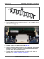
1
PRIMERGY
PRIMERGY RX600 S3 SAS Server
Options Guide
Joachim Pichol
Fujitsu Siemens Computers GmbH Paderborn
33094 Paderborn
e-mail: email: [email protected]
Tel.: (05251) 148 88-18
Fax: 0 700 / 372 00001
Sprachen: En
Edition January 2007
Comments… Suggestions… Corrections…
The User Documentation Department would like to
know your opinion of this manual. Your feedback helps
us optimize our documentation to suit your individual
needs.
Fax forms for sending us your comments are included in
the back of the manual.
There you will also find the addresses of the relevant
User Documentation Department.
Certified documentation
according to DIN EN ISO 9001:2000
To ensure a consistently high quality standard and
user-friendliness, this documentation was created to
meet the regulations of a quality management system
which complies with the requirements of the standard
DIN EN ISO 9001:2000.
cognitas. Gesellschaft für Technik-Dokumentation mbH
www.cognitas.de
Copyright and Trademarks
Copyright © 2007 Fujitsu Siemens Computers GmbH.
All rights reserved.
Delivery subject to availability; right of technical modifications reserved.
All hardware and software names used are trademarks of their respective manufacturers.
Contents
1
Preface . . . . . . . . . . . . . . . . . . . . . . . . . . . . . . 5
1.1
Documentation overview . . . . . . . . . . . . . . . . . . . . 5
1.2
Extensions and conversions . . . . . . . . . . . . . . . . . . 7
1.3
Notational conventions . . . . . . . . . . . . . . . . . . . . . 9
2
Procedure
. . . . . . . . . . . . . . . . . . . . . . . . . . .
11
3
Important notes . . . . . . . . . . . . . . . . . . . . . . . .
13
3.1
Notes on safety
. . . . . . . . . . . . . . . . . . . . . . . .
13
3.2
Environmental protection . . . . . . . . . . . . . . . . . . .
19
4
Preparation . . . . . . . . . . . . . . . . . . . . . . . . . . .
23
4.1
Opening the server
. . . . . . . . . . . . . . . . . . . . . .
23
5
Main memory . . . . . . . . . . . . . . . . . . . . . . . . . .
25
5.1
Fitting rules . . . . . . . . . . . . . . . . . . . . . . . . . . .
26
5.2
Upgrading / exchanging main memory . . . . . . . . . . . .
27
6
Processors . . . . . . . . . . . . . . . . . . . . . . . . . . .
31
6.1
Installing additional processors
. . . . . . . . . . . . . . .
31
6.2
Replacing the processor
. . . . . . . . . . . . . . . . . . .
40
7
Accessible drives . . . . . . . . . . . . . . . . . . . . . . .
43
7.1
Installing the CD/DVD drive . . . . . . . . . . . . . . . . . .
43
7.2
Installing a tape drive . . . . . . . . . . . . . . . . . . . . .
47
Options Guide RX600 S3 SAS
Contents
8
Controllers in non-hot-plug PCI slots
. . . . . . . . . . . .
51
8.1
Installing controllers . . . . . . . . . . . . . . . . . . . . . .
51
9
RemoteView components . . . . . . . . . . . . . . . . . . .
53
9.1
Installing the RemoteView Service Board S2 LP . . . . . . .
53
10
External SCSI connection . . . . . . . . . . . . . . . . . . .
57
10.1
Installing an external SCSI connection . . . . . . . . . . . .
58
11
Battery for the RoMB controller . . . . . . . . . . . . . . . .
61
11.1
Installing the battery (BBU) . . . . . . . . . . . . . . . . . .
61
12
Completion . . . . . . . . . . . . . . . . . . . . . . . . . . .
65
12.1
Closing the server . . . . . . . . . . . . . . . . . . . . . . .
65
Abbreviations . . . . . . . . . . . . . . . . . . . . . . . . . . . . . . .
67
Related publications . . . . . . . . . . . . . . . . . . . . . . . . . . .
75
Index . . . . . . . . . . . . . . . . . . . . . . . . . . . . . . . . . . . .
77
Options Guide RX600 S3 SAS
1
Preface
The PRIMERGY RX600 S3 SAS server is an Intel-based server for mid-size
and large companies. It is suitable for use as a file server as well as an
application, information, or Internet server.
The server offers a high degree of reliability and availability through highly
developed hardware and software components. These include hard disk drive
modules, system fans, power supply units, PCI slots and memory boards (all the
components listed are hot-pluggable), as well as “Prefailure Detection and
Analyzing” (PDA), “Automatic Server Reconfiguration and Restart” (ASR&R)
and the ServerView server management software.
The server is used exclusively as a rack model. It offers a whole host of
configuration options but only uses four height units (HU) in the 19-inch rack.
1.1
Documentation overview
I PRIMERGY manuals are available in PDF format on the ServerBooks CD,
which is part of the ServerView Suite package provided with each server
system.
These PDF files can also be downloaded from the Internet free of
charge: At http://manuals.fujitsu-siemens.com you will find an overview
page showing the online documentation available on the Internet.
You can go to the PRIMERGY server documentation by clicking on
industry standard servers.
Concept and target groups
This Options Guide shows you how to expand and upgrade your server.
V Caution!
The activities described in this manual may only be performed by
specialist personnel with technical training.
I The installation and removal of the hot-plug components is described in
the operating manual supplied with the server.
Options Guide RX600 S3 SAS
5
Documentation overview
Preface
Additional server documentation
The PRIMERGY documentation comprises the following additional manuals:
– The “Safety notes and other important information” manual (printed copy
always supplied with the server, and available as a PDF file on the
ServerBooks CD supplied)
– The “Guarantee” manual (printed copy always supplied with the server; also
available as a PDF file on the supplied ServerBooks CD)
– The “Ergonomics” manual (PDF file available on the supplied ServerBooks
CD)
– The operating manual for PRIMERGY RX600 S3 SAS (PDF file available on
the ServerBooks CD supplied)
– The technical manual for the system board D2630 (PDF file available on the
ServerBooks CD supplied)
– The “D2630 BIOS Setup” manual (PDF file available on the ServerBooks CD
supplied)
– The Service Supplement for PRIMERGY RX600 S3 SAS (PDF file
available on the ServerBooks CD supplied)
– The “ServerView Suite” manual (printed copy always supplied with the
server, and available as a PDF file on the ServerBooks CD supplied)
– The “WebBIOS Configuration Utility” (PDF file available on the ServerBooks
CD supplied)
I You can order a supplementary ServerBooks CD by sending an e-mail to
the following address, quoting your server data:
[email protected]
Further sources of information:
–
–
–
–
–
–
–
Technical manual for the relevant rack
Manual for the monitor
Manual on ServerView Server Management
Manual on the RemoteView Remote Test and Diagnostics System
Documentation for boards and drives
Documentation for your operating system
Information files on your operating system
(See also chapter “Related publications” on page 75)
6
Options Guide RX600 S3 SAS
Preface
1.2
Extensions and conversions
Extensions and conversions
Additional processors
The system board can be upgraded to include up to four processors. You may
only use processors of the same type on the system board. All processors must
have the same frequency and cache size.
Extension of the main memory
The system board offers slots for four hot-plug memory boards, each of which
can accommodate up to four memory modules (in two memory banks) The slots
are suitable for DDR II/400 MHz DIMM modules with 1 GB, 2 GB and 4 GB
capacity. This allows a maximum memory configuration of 64GB.
Additional accessible drive
In addition to the existing CD-/DVD drive, a tape drive can be installed as an
accessible drive. The slot is designed for 5.25 x 1.6-inch devices.
Additional controllers in non-hot-plug PCI slots
The system board has seven PCI slots:
●
Slots 1-5 are hot-plug PCI slots which can be fitted with hot-pluggable
controllers (the hot-plug PCI slots are described in the operating manual).
I Slot 4 comes with a SAS controller installed and can thus not be fitted
with other controllers.
●
Slots 6 and 7 are 100 MHz non-hot-plug PCI slots and can be fitted with
boards with a maximum length of 315mm.
Additional external SCSI interface
If you want to connect additional external SCSI devices, one channel of the
onboard controller can be made available for connecting storage subsystems
via the external SCSI interface.
Battery (BBU) for the RoMB controller
An optional battery (battery backup unit = BBU) is available for the internal
RoMB controller to protect its memory contents in the event of a power failure.
Options Guide RX600 S3 SAS
7
Extensions and conversions
Preface
RemoteView
RemoteView is the remote-management solution for PRIMERGY systems from
Fujitsu Siemens Computers. RemoteView and the associated hardware
components integrated on the system board allow remote monitoring and
servicing and fast recovery of the system in the event of an error.
RemoteView Service Board S2 LP
The RemoteView Service Board S2 “low profile” (RSB S2 LP) is a PCI board with
a completely independent system, i.e. it has its own operating system with Web
server and SNMP agents and can optionally be equipped with an external
power supply.
The RSB S2 LP is installed in a (non-hot plug) standard PCI slot and connected
to the system board with a cable.
The RSB S2 LP permits remote diagnosis for system analysis, remote system
configuration and restart in the event of operating system failure or hardware
faults. It has its own LAN port which ensures that all the functions are available.
8
Options Guide RX600 S3 SAS
Preface
1.3
Notational conventions
Notational conventions
The following notational conventions are used in this manual:
Italics
indicate commands, menu items or software programs.
“Quotation marks”
indicate names of chapters and terms that need to be
emphasized.
Ê
indicates an activity that must be performed.
V ATTENTION!
I
indicates that, if you ignore the information given at this
point, your health, the correct functioning of your
system or the security of your data may be at risk.
indicates supplementary information, remarks and tips.
Table 1: Notational conventions
Options Guide RX600 S3 SAS
9
2
Procedure
V ATTENTION!
●
The activities described in this manual should only be performed by
engineers, service personnel or technical specialists.
●
Equipment repairs should only be performed by qualified staff.
●
Any failure to observe the guidelines in this manual, and any
unauthorized opening or improper repairs could endager the user
(through electric shock, fire hazards) or damage the equipment.
●
Please note that any unauthorized opening of the device will result in
the invalidation of the warranty and exclusion from all liability.
Ê First of all please familiarize yourself with the safety instructions in the
chapter “Important notes” on page 13ff.
Ê Make sure that all the manuals you need (see “Additional server
documentation” on page 6) are available, printing out the PDF files if
necessary.
You will definitely need
– the operating manual for the server,
– the Service Supplement for the server and
– the technical manual for the system board.
Ê Shut down the server correctly, switch it off, pull out the power plugs, and
open the server as described in the chapter “Preparation” on page 23f.
Ê Extend or upgrade your server as described in the relevant chapter.
I The installation and removal of the hot-plug components is described
in the operating manual supplied with the server.
Ê Close the server, plug in the power plugs, and switch on the server as
described in the chapter “Completion” on page 65f.
Ê Start the operating system and, if necessary, configure it as required (see
the operating manual).
Options Guide RX600 S3 SAS
11
3
Important notes
This chapter provides safety instructions which you must observe when
handling your server.
3.1
Notes on safety
I The following safety instructions can also be found in the manual entitled
“Safety”.
This device complies with the relevant safety regulations for data processing
equipment, including electronic office machines for use in an office
environment.
If you have any questions as to whether you can set up the device in your
particular environment, please contact your sales outlet or our customer service
center.
V ATTENTION!
The activities described in this manual may only be performed by
specialist technical personnel. Equipment repairs must only be
performed by qualified staff. Any unauthorized opening or improper
repairs could endanger the user (through electric shock, energy hazard,
fire hazard) or damage the equipment. Please note that any
unauthorized opening of the device will result in the invalidation of the
warranty and exclusion from all liability.
Options Guide RX600 S3 SAS
13
Notes on safety
Important notes
Before setting up
V ATTENTION!
●
During installation and before operating the device, observe the
instructions on environmental conditions for your device (see
operating manual).
●
If the device is brought in from a cold environment, condensation may
form both inside and on the outside of the machine.
Before operating the device, wait until it is absolutely dry and has
reached approximately the same temperature as the installation site.
Failure to observe these guidelines can lead to material damage of
the device.
●
Transport the device only in its original packaging or in packaging
which protects it from knocks and jolts.
Installation and operation
V ATTENTION!
14
●
If the rack model is integrated in an installation that receives power
from an industrial (public) power supply network with the IEC309
connector, the (public) power supply protection must comply with the
requirements for the non-industrial power supply networks for the
type A connector.
●
The server automatically adjusts to a mains voltage from 200 V - 240 V.
Make sure that the local mains voltage is neither above nor below this
range.
●
This device has safety-tested power cables and must only be
connected to properly grounded power outlets.
●
Make sure that the power sockets on the device or the grounded
mains outlets are freely accessible.
●
The power switch does not disconnect the device from the mains
voltage. To completely disconnect it from the mains voltage, you must
remove the power plugs from the power outlet.
Options Guide RX600 S3 SAS
Important notes
Notes on safety
V ATTENTION!
●
Always connect the device and the attached peripherals to the same
power circuit. Otherwise you run the risk of losing data if, for example,
a power outage occurs and the central processing unit is still running
but the peripheral device (e.g. a storage subsystem) has failed.
●
Data cables must be adequately shielded to avoid interference.
●
For the LAN wiring, the requirements according to standards EN
50173 and EN 50174-1/2 apply. The minimum requirement is the use
of a protected LAN line of category 5 for 10/100 Mbps Ethernet,
and/or of category 5e for Gigabit Ethernet. The requirements of the
specification ISO/IEC 11801 must also be taken into account.
●
Route the cables in such a way that they do not form a potential
hazard (tripping) and cannot be damaged. When connecting the
device, refer to the relevant notes in the operating manual.
●
Do not connect or disconnect any data transmission cables during a
thunderstorm (lightning hazard).
●
Be careful to ensure that no objects (e.g. jewelry, paper clips etc.) or
liquids get inside the device (electric shock, short circuit).
●
In emergencies (e.g. damaged casing, control elements or cable,
penetration of liquids or foreign bodies), switch off the device
immediately, unplug it from the grounded power outlet, and contact
your customer service center.
●
Proper operation of the device (in accordance with IEC 60950-1/
EN 60950-1) is only ensured if the casing is completely assembled
and the rear covers for the installation openings are in place (electric
shock, cooling, fire protection, interference suppression).
Options Guide RX600 S3 SAS
15
Notes on safety
Important notes
V ATTENTION!
●
Install only system extensions that satisfy the requirements and rules
governing safety, electromagnetic compatibility, and
telecommunications terminal equipment.
If you install other extensions, you may damage the system or violate
these safety regulations.
Information on which system extensions are suitable can be obtained
from the customer service center or your sales outlet.
●
The components marked with a warning label (e.g. lightning symbol)
may only be opened, removed, or exchanged by authorized, qualified
personnel.
Exception: You may exchange hot-plug power supply units.
●
If you cause a defect on the device by installing or exchanging system
extensions, the warranty will be invalidated.
●
You may only set the resolutions and refresh rates specified in the
operating manual for your monitor.
Otherwise, you may damage the monitor. If you are in any doubt,
contact your sales outlet or customer service center.
Batteries
V ATTENTION!
●
Incorrect replacement of batteries can lead to risk of explosion. The
batteries may only be replaced with identical batteries or with a type
recommended by the manufacturer (see the technical manual for the
system board in the section “Documentation overview” on page 5).
●
When replacing the lithium battery on the system board, always follow
the instructions in the technical manual for the system board (see
section “Documentation overview” on page 5).
Notes on handling CDs/DVDs in CD/DVD drives
V ATTENTION!
●
16
To prevent data loss, damage to the device, or injuries, you should
use only CDs/DVDs in good condition in the CD/DVD drive of your
server.
Options Guide RX600 S3 SAS
Important notes
●
Notes on safety
Therefore, check each CD/DVD for damage, cracks, breakage etc.
before inserting it in the drive.
Please note that any additional labels applied may change the
mechanical properties of a CD/DVD and cause imbalance.
Damaged and imbalanced CDs/DVDs can break at high drive speeds
(data loss).
Under certain conditions, sharp-edged pieces of broken CDs/DVDs
can penetrate the cover of the drive (cause damage to the device)
and be thrown out of the device (therefore causing injury to
uncovered body parts, particularly the face or neck).
I To protect the CD/DVD drive and prevent mechanical damage as well as
premature wearing of the CDs/DVDs, you should observe the following
advice:
– Only insert the CDs/DVDs in the drive when needed and remove
them after use.
– Store the CDs/DVDs in suitable sleeves.
– Protect the CDs/DVDs from exposure to heat and direct sunlight.
Note on the laser
The CD/DVD drive is classified as Laser Class 1, according to IEC 60825-1.
V ATTENTION!
The CD/DVD drive contains a light-emitting diode (LED) which may
generate a stronger laser beam than laser class 1. It is dangerous to look
directly into the beam.
Never remove any parts of the housing of the CD/DVD drive!
Options Guide RX600 S3 SAS
17
Notes on safety
Important notes
Components with electrostatic-sensitive devices
Components with electrostatic-sensitive devices are identified by the following
sticker:
Figure 1: ESD label
When you handle components fitted with ESDs, you must always observe the
following points:
●
Pull out the power plug before installing or uninstalling components.
●
You must always discharge static build-up (e.g. by touching a grounded
object) before working with such components.
●
Any devices or tools that are used must be free of electrostatic charge.
●
Wear a suitable grounding cable that connects you to the external chassis of
the system unit.
●
Always hold components with ESDs at the edges or at the points marked
green (touch points).
●
Do not touch any connectors or conduction paths on an ESD.
●
Place all the components on a pad which is free of electrostatic charge.
I For a detailed description of how to handle ESD components, see the
relevant European or international standards (EN 61340-5-1, ANSI/ESD
S20.20).
18
Options Guide RX600 S3 SAS
Important notes
3.2
Environmental protection
Environmental protection
Environmentally friendly product design and development
This product has been designed in accordance with the Fujitsu Siemens
Computers standard “Environmentally Friendly Product Design and
Development”. This means that the designers have taken into account
important criteria such as durability, selection and labeling of materials,
emissions, packaging, the ease with which the product can be dismantled and
the extent to which it can be recycled.
This saves resources and helps to protect the environment.
Notes on saving energy
Devices that do not have to be on permanently should not be switched on until
they are needed and should be switched off during long breaks and when work
is finished.
Notes on dealing with consumables
Please dispose of printer consumables and batteries in accordance with local
government regulations.
Do not throw batteries into the household rubbish. They must be disposed of in
accordance with local regulations on special waste.
Note on labels on plastic housing parts
Avoid attaching your own labels on plastic housing parts whenever possible,
since this makes it difficult to recycle them.
Options Guide RX600 S3 SAS
19
Environmental protection
Important notes
Returning used electrical and electronic devices
●
Separate disposal
Old electrical and electronic devices must be disposed of separately and not
with household refuse. Separate disposal allows this old equipment to be
reused or recycled, which helps conserve resources.
●
Return and collection systems
It may be possible to return old electrical/electronic devices from private
households free of charge. Please use the country-specific return or
collection systems available to you (see “Local contacts” on page 21).
The return of used devices which pose a health or safety risk for human
beings due to soiling during use may be refused.
●
Reuse and recycling
By actively using any return or collection systems offered, you will be
contributing to the reuse and recycling of electrical/electronic devices.
●
Effects on the environment and human health
Old electrical/electronic devices contain parts which must be handled
selectively according to EU directives. Separate disposal and selective
treatment are the basis for environment-friendly disposal and the protection
of human health.
●
Meaning of the symbol “Crossed out rubbish bin on wheels"
In accordance with EU directives, electrical (electronic) devices which are
marked with one of the following symbols must not be disposed of with
household refuse.
Figure 2: Symbols on electrical/electronic devices
20
Options Guide RX600 S3 SAS
Important notes
Environmental protection
Returning batteries
According to EU directives, batteries which are marked with one of the following
symbols must not be disposed of together with household refuse.
Figure 3: Symbols on batteries
With batteries containing harmful substances, the chemical symbol for the
heavy metal contained is indicated below the rubbish bin.
Cd Cadmium
Hg Mercury
Pb Lead
The following applies to Germany:
– Private consumers can return batteries at the point of sale or in the
immediate vicinity thereof free of charge.
– The consumer is obligated to return defective or used batteries to the seller
or to the return points established for this purpose.
Local contacts
For details on take-back and reuse of devices and consumables within Europe,
contact your Fujitsu Siemens Computers branch office/subsidiary or our
recycling centre in Paderborn, Germany:
Fujitsu Siemens Computers
Recycling Center
33106 Paderborn, Germany
Tel.:
+49 5251 8180-10
Fax:
+49 5251 8180-15
Internet: www.fujitsu-siemens.com/recycling
Options Guide RX600 S3 SAS
21
4
Preparation
V ATTENTION!
Make sure you observe the safety notes in the chapter “Important notes”
on page 13ff.
Ê Exit all applications and shut down the server correctly.
Ê If your operating system has not switched off the server, press the On/Off
button.
Ê Unplug the power plugs from the grounded power outlets.
4.1
Opening the server
Figure 4: Removing the server
Ê Undo the knurled screws (1) and pull the server carefully out of the rack (2)
as far as possible.
Ê In the majority of cases it makes sense to remove the server from the rack.
I How to remove the server from the rack cabinet is described in the
operating manual.
Options Guide RX600 S3 SAS
23
Opening the server
Preparation
2
1
Figure 5: Removing the housing cover
Ê Undo the two captive screws on the front (1).
Ê Push the housing cover back a few centimeters (2).
Ê Take off the housing cover.
24
Options Guide RX600 S3 SAS
5
Main memory
V ATTENTION!
Make sure you observe the safety notes in the chapter “Important notes”
on page 13ff.
I In redundant (mirroring or RAID) configurations, defective memory
boards can be replaced while the system is running (“hot plug”). The
relevant procedure is described in the operating manual supplied with the
server.
This manual describes how to replace memory boards when the system
is switched off.
The system board provides slots for four hot-plug memory boards, each of
which can accommodate up to four memory modules. Two memory modules
(“1A/1B” or “2A/2B”) make up one memory bank (see figure 6 on page 26).
The slots are suitable for DDR II/400 MHz DIMM modules with 1 GB, 2 GB and
4 GB capacity. This allows a maximum memory configuration of 64GB.
Options Guide RX600 S3 SAS
25
Fitting rules
5.1
Main memory
Fitting rules
V ATTENTION!
Memory modules must be installed in pairs of identical modules.
Figure 6: Fitting the memory banks
The memory capacity of the pairs installed on a memory board, however,
may differ: pair 1A/1B, for example, can consist of two 2 GB memory
modules and pair 2A/2B of two 1 GB memory modules.
26
Options Guide RX600 S3 SAS
Main memory
5.2
Upgrading / exchanging main memory
Upgrading / exchanging main memory
Ê Open the server as described in chapter “Preparation” on page 23f.
Figure 7: Pressing on the handle lock
Ê Press the clip in the handle so that the handle can eject.
Figure 8: Removing the memory board
Ê Carefully pull out the memory board by the handle.
Options Guide RX600 S3 SAS
27
Upgrading / exchanging main memory
Main memory
3
2
1
Figure 9: Removing the memory board cover
Ê Remove the memory cover by pressing the marked clips. First press on clip
“1” and then clips “2” and “3”.
Figure 10: Removing a memory module
Ê Flip the ejector tabs on each side of the slot outward (1). This levers an
installed memory module out of its slot.
Ê Remove the memory module from the slot (2).
28
Options Guide RX600 S3 SAS
Main memory
Upgrading / exchanging main memory
Figure 11: Installing a memory module
Ê Carefully press the memory module into the slot (1) until the ejector tabs on
both sides of it engage (2).
Figure 12: Fitted memory board
Ê Place the cover on the memory board (see page 28).
Ê Carefully reinstall the memory board in its slot in the server, exerting equal
pressure on both sides of the board. (For a detailed description of how to
install the board see the operating manual.)
Ê Close the server, plug in the power plugs, and switch on the server as
described in the chapter “Completion” on page 65f.
Options Guide RX600 S3 SAS
29
6
Processors
V ATTENTION!
Make sure you observe the safety notes in the chapter “Important notes”
on page 13ff.
Processors are components which are extremely sensitive to
electrostatic discharge and must be handled with caution.
When you take a processor out of its protective wrapper or out of a
socket, place it on an insulated, antistatic surface with the smooth side
down.
Never slide a processor over a surface.
6.1
Installing additional processors
The system board can be upgraded to include up to four processors.
V ATTENTION!
Always use processors of the same type. All processors must have the
same frequency and cache size. For multi-processor mode use a
suitable multi-processor operating system.
Ê Open the server as described in the chapter “Preparation” on page 23f.
Options Guide RX600 S3 SAS
31
Installing additional processors
Processors
Removing the processor cover
Figure 13: Removing the processor cover
Ê Insert your fingers in the two recesses in the processor cover and lift it
upward.
32
Options Guide RX600 S3 SAS
Processors
Installing additional processors
Removing the heat sink dummy
CPU 1
CPU 2
CPU 4
CPU 3
Figure 14: Heat sink dummies on the CPU sockets 2 - 4
Ê Undo the four captive screws at the foot of the heat sink dummy on the
relevant processor socket and remove the dummy.
I When installing heat sinks, note that the numbering of the CPUs/CPU
sockets corresponds with the fitting sequence.
Options Guide RX600 S3 SAS
33
Installing additional processors
Processors
Installing the processor
Figure 15: Opening the socket lever
Ê Release the socket lever by pressing it sideways and then lifting it up as far
as it will go.
Figure 16: Inserting the processor
V ATTENTION!
The processor can only be installed in one direction. Note the marking
on one of the corners (see diagram above).
To avoid damaging the pins or the processor, do not force the processor
into the socket.
Ê Position the new processor above the socket, and press it carefully into the
socket (1).
Ê Lock the processor into place in the socket by pushing the socket lever back
into its original position (2).
34
Options Guide RX600 S3 SAS
Processors
Installing additional processors
Installing the heat sink
V ATTENTION!
Never install a processor without a heat sink, as the processor may
overheat, causing itself and the complete system board to fail.
Ê Carefully place the heat sink onto the processor.
I Make sure the thermal paste on the underside of the heat sink is not
damaged.
Figure 17: Fastening the heat sink
Ê Fasten the heat sink with four screws. First fasten two diagonally opposite
screws, then the other two.
Options Guide RX600 S3 SAS
35
Installing additional processors
Processors
Installing additional VRM modules
A
B
Figure 18: Additional VRM modules
Ê Install a separate core VRM module (A) for the 3rd and 4th CPUs.
I For third-level size cache processors (e.g. "Tulsa"), an additional cache
VRM module "VRM 9DO" (B) must be installed for the 3rd and 4th CPU
together.
A
Figure 19: Ventilation hood for the core VRM module of CPU 4.
I This ventilation hood shown above must be removed before you install
the core VRM module of the 4th CPU and must be reinstalled afterwards.
Ê Slide the plastic catch (A) under a cross-bar on the chassis (see figure 21
on page 38).
36
Options Guide RX600 S3 SAS
Processors
Installing additional processors
A2
A1
B
Figure 20: Position of the additional VRM modules to be installed
Ê Install the required VRM modules in the appropriate slots:
– the core VRM module (A1) for the 3rd CPU.
– the core VRM module (A2) for the 4th CPU.
– the cache VRM module "VRM 9DO" (B) for the 3rd and 4th CPUs.
I The additional cache VRM module is only required for third-level
size cache processors (e.g. "Tulsa").
Options Guide RX600 S3 SAS
37
Installing additional processors
Processors
Figure 21: Installing the ventilation hood for the core VRM module of the 4th CPU
Ê Install the ventilation hood for the core VRM module of the 4th CPU as
follows:
– Insert the plastic catch (see figure 19 on page 36) into the slot of the
chassis cross-bar (see circle in figure above).
– Swivel the ventilation hood downward.
38
Options Guide RX600 S3 SAS
Processors
Installing additional processors
Mounting the processor cover
Figure 22: Mounting the processor cover
Ê Reinstall the processor cover.
I Make sure the processor cover engages properly by pressing the
points marked "Memory" (see circles) on the cover.
Ê Close the server, plug in the power plugs, and switch on the server as
described in the chapter “Completion” on page 65f.
Options Guide RX600 S3 SAS
39
Replacing the processor
6.2
Processors
Replacing the processor
V ATTENTION!
You may only use processors of the same type on the system board.
Ê Open the server as described in the chapter “Preparation” on page 23f.
Ê Remove the processor cover (see page 32)
Figure 23: Removing the processor heat sink
Ê Remove the four screws of the heat sink. First undo two diagonally opposite
screws, then the other two.
Ê Turn the heat sink carefully back and forth to loosen it. Then lift it out to
remove it.
Ê Remove the residual thermal paste from the underside of the heat sink.
Ê Clean the underside of the heat sink using a lint-free cloth.
40
Options Guide RX600 S3 SAS
Processors
Replacing the processor
Figure 24: Removing the old processor
Ê Release the socket lever by pressing it sideways and lifting it up as far as it
will go (1).
Ê Lift the installed processor carefully out of its socket (2).
Installing the new processor
V ATTENTION!
The processor can only be installed in one direction. Note the marking
on one of the corners (see figure below).
To avoid damaging the pins or the processor, do not force the processor
into the socket.
Figure 25: Installing the new processor
Ê Position the new processor above the socket, and press it carefully into the
socket (1).
Ê Lock the processor into place in the socket by pushing the socket lever back
into its original position (2).
Options Guide RX600 S3 SAS
41
Replacing the processor
Processors
Ê Carefully place the heat sink onto the processor.
I Make sure the thermal paste on the underside of the heat sink is not
damaged.
Ê Fasten the heat sink with four screws (see page 35). First fasten the two
diagonally opposite screws, then the other two.
Ê Reinstall the processor cover (see page 39).
Ê Close the server, plug in the power plugs, and switch on the server as
described in the chapter “Completion” on page 65f.
42
Options Guide RX600 S3 SAS
7
Accessible drives
V ATTENTION!
Make sure you observe the safety notes in the chapter “Important notes”
on page 13ff.
The PRIMERGY RX600 S3 SAS server offers a total of two slots for accessible
drives. Possible options are a tape drive and a CD/DVD drive.
7.1
Installing the CD/DVD drive
B
A
Figure 26: CD/DVD drive with module frame
A CD/DVD drive (B) can be installed in the server. This drive is installed in the
server in a module frame (A).
Removing the module frame
The module frame for the CD/DVD drive is installed in the slot.
Ê Open the server as described in the chapter “Preparation” on page 23f.
Options Guide RX600 S3 SAS
43
Installing the CD/DVD drive
Accessible drives
A
Figure 27: Removing the module frame
Ê Press the blue lever (A) and push the module frame out of the server.
Mounting a CD/DVD drive
B
A
Figure 28: Mounting the interface board
Ê Connect the interface board (A) into the rear interface connector (B) of the
CD/DVD drive.
44
Options Guide RX600 S3 SAS
Accessible drives
Installing the CD/DVD drive
Figure 29: Mounting the drive in its frame
Ê Place the CD/DVD drive in the frame such that it engages in the two
openings of the module frame (see circles).
Figure 30: The pre-mounted CD/DVD drive (back)
Ê Push the CD/DVD drive into its bay from the front until it engages.
Options Guide RX600 S3 SAS
45
Installing the CD/DVD drive
Accessible drives
B
A
Figure 31: Installing the CD/DVD drive
Ê Plug the data cable (A) and the power cable (B) into the interface board of
the CD/DVD drive.
Ê Close the server, plug in the power plugs, and switch on the server as
described in the chapter “Completion” on page 65f.
46
Options Guide RX600 S3 SAS
Accessible drives
7.2
Installing a tape drive
Installing a tape drive
A tape drive can be installed in the bay in the middle of the server. If no device
is installed in the bay, it contains only the module frame.
Removing the module frame
Ê Open the server as described in the chapter “Preparation” on page 23f.
Figure 32: Removing the module frame
Ê Press the two blue points on the spring clips on the module frame and push
the module frame forward out of the server.
Options Guide RX600 S3 SAS
47
Installing a tape drive
Accessible drives
Figure 33: Module frame with sliding rails
Ê Undo the two screws to remove the two sliding rails on the sides.
V ATTENTION!
Keep the module frame for future use. If you remove the drive without
installing a new one, you must reinstall the module frame to comply with
EMC regulations and to satisfy cooling requirements and fire protection
measures.
48
Options Guide RX600 S3 SAS
Accessible drives
Installing a tape drive
Figure 34: Fastening the sliding rails on the drive
Ê Fasten the two sliding rails on both sides of the drive to be installed using
two screws for each.
Figure 35: Inserting the tape drive
Ê Push the accessible drive into the empty bay until it engages.
Options Guide RX600 S3 SAS
49
Installing a tape drive
Accessible drives
Mounting the tape drive
A
B
Figure 36: Connecting the drive
Ê Connect the data cable (A) to the drive.
Ê Connect the power cable (B) to the drive.
Ê Connect the free end of the data cable either to the connector for SCSI
channel “B” on the system board or to a free connector on a PCI SCSI
controller.
Ê Close the server, plug in the power plugs, and switch on the server as
described in the chapter “Completion” on page 65f.
50
Options Guide RX600 S3 SAS
8
Controllers in non-hot-plug PCI
slots
V ATTENTION!
Make sure you observe the safety notes in the chapter “Important notes”
on page 13ff.
The system board contains two non-hot-plug PCI-X slots (slots 6 and 7) with the
following specifications: 64 bit/100 MHz, max. length 315 mm
When replacing non-hot-pluggable components, you must proceed as follows:
Ê Exit all applications and shut down the server correctly.
Ê If your operating system has not switched off the server, press the On/Off
button.
Ê Unplug the power plugs from the grounded power outlets.
8.1
Installing controllers
Ê Open the server as described in the chapter “Preparation” on page 23f.
Ê Please read the documentation supplied with the PCI board.
Ê Plug any necessary cables into the PCI board.
Ê Remove the slot cover of the relevant slot on the back side of the server.
I Keep the slot cover.
If you remove a board, you must reinstall the slot cover to comply with
EMC regulations (regulations on electromagnetic compatibility) and
to satisfy cooling requirements and fire protection measures.
Options Guide RX600 S3 SAS
51
Installing controllers
Controllers in non-hot-plug PCI slots
A
Figure 37: Installing a non-hot-plug controller
Ê Insert the controller in the slot and press it in carefully. Close the locking
mechanism of the slot (A).
Ê If necessary, plug in the cables on the board and other components.
Ê Close the server, plug in the power plugs, and switch on the server as
described in the chapter “Completion” on page 65f.
52
Options Guide RX600 S3 SAS
9
RemoteView components
V ATTENTION!
Make sure you observe the safety notes in the chapter “Important notes”
on page 13ff.
The RemoteView Service Board S2 LP (RSB S2 LP) is a low-profile PCI board
including a completely independent system, i.e. it has a separate operating
system with a Web server and SNMP agent and can be driven by an external
power supply.
The RSB S2 LP is connected to the system board via an IPMB cable. It permits
remote diagnosis for system analysis, remote system configuration and remote
restart even in the event of operating system failure or hardware faults.
9.1
Installing the RemoteView Service Board
S2 LP
Ê Open the server as described in the chapter “Preparation” on page 23f.
Ê Remove the slot cover of a (non-hot-plug) PCI slot on the back side of the
server.
I The RSB S2 LP should preferably be installed in the (non-hot-plug)
PCI slot 7.
Keep the slot cover.
If you remove the board, you must reinstall the slot cover to comply
with EMC regulations (regulations on electromagnetic compatibility)
and to satisfy cooling requirements and fire protection measures.
Options Guide RX600 S3 SAS
53
Installing the RemoteView Service Board S2 LP RemoteView components
A
Figure 38: Mounting position and connectors of the RSB S2 LP
Ê Install the RSB S2 LP in the PCI slot. The relevant procedure is described in
the chapter “Controllers in non-hot-plug PCI slots” on page 51ff.
54
Options Guide RX600 S3 SAS
RemoteView components Installing the RemoteView Service Board S2 LP
1
2
4
3
Figure 39: Connectors of the RSB S2 LP
1
Connector for the adapter cable (connector for the external power
supply and USB and VGA connection)
2
Connector for the optional power supply (not used)
3
IPMB connector
4
LAN connector
Ê Plug the IPMB cable supplied with the server into the plug (see (3) in the
figure 39) on the RSB S2 LP.
Ê Check that the IPMB cable is connected to the system board (see (A) in
figure 38 on page 54).
I The position of the connectors is described in the technical manual
for the D2630 system board.
Ê Close the server, plug in the power plugs, and switch on the server as
described in the chapter “Completion” on page 65f.
Options Guide RX600 S3 SAS
55
10
External SCSI connection
V ATTENTION!
Make sure you observe the safety notes in the chapter “Important notes”
on page 13ff.
The connection for external SCSI devices is located on the rear of the server.
Figure 40: Position of the external SCSI connection
Options Guide RX600 S3 SAS
57
Installing an external SCSI connection
10.1
External SCSI connection
Installing an external SCSI connection
Install the following cable (FSC no. A3C40079949):
A
B
Figure 41: Cable for the external SCSI connection
A
Connector for connecting exernal SCSI devices
B
Connector for connecting to “SCSI B" on the system board
Ê Open the server as described in the chapter “Preparation” on page 23f.
Ê Remove the memory boards or dummy memory boards installed in slots "C"
and "D".
58
Options Guide RX600 S3 SAS
External SCSI connection
Installing an external SCSI connection
A
Figure 42: Installing the connector in the server backplane
Ê Plug the connector (A) of the connection cable into the corresponding
opening in the backplane.
I Make sure the connector engages properly.
Ê Connect the connector (B) of the connection cable (see figure 41 on
page 58) to the “SCSI B" connector on the system board.
Ê Close the server, plug in the power plugs, and switch on the server as
described in the chapter “Completion” on page 65f.
Options Guide RX600 S3 SAS
59
11
Battery for the RoMB controller
V ATTENTION!
Make sure you observe the safety notes in the chapter “Important notes”
on page 13ff.
11.1
Installing the battery (BBU)
A
B
C
Figure 43: Components of the optional BBU package
A
Battery holder
B
Battery
C
Connection cable to the system board
Ê Open the server as described in the chapter “Preparation” on page 23f.
Ê Remove the memory boards or dummy memory boards installed in slots "C"
and "D".
Options Guide RX600 S3 SAS
61
Installing the battery (BBU)
Battery for the RoMB controller
A
B
Figure 44: Connecting the internal and external cable to the battery
Ê Connect the plug of the internal cable to the internal battery connector (A).
Ê Connect the plug of the connection cable to the system board to the external
connector of the battery (B) through the opening of the battery holder.
Ê Close the battery holder.
62
Options Guide RX600 S3 SAS
Battery for the RoMB controller
Installing the battery (BBU)
A
Figure 45: Fastening the battery holder and routing the connection cable
Ê Fasten the battery holder in the recesses provided in the side of the housing
(A).
B
A
Figure 46: Attaching the connection cable to the system board
Ê Route the connection cable through the opening in the ventilation foil (A).
Ê Plug the connection cable to the connector "J1H1" on the system board (B).
Options Guide RX600 S3 SAS
63
Installing the battery (BBU)
Battery for the RoMB controller
I The connector "J1H1" has a small plastic cover which must be
removed first.
Ê Reinstall the memory boards or dummy memory boards in slots "C" and "D".
Ê Close the server, plug in the power plugs, and switch on the server as
described in the chapter “Completion” on page 65f.
64
Options Guide RX600 S3 SAS
12
Completion
V ATTENTION!
Make sure you observe the safety notes in the chapter “Important notes”
on page 13ff.
12.1
Closing the server
Figure 47: Mounting the housing cover
Ê Position the cover in such a way that the rear edge protrudes 1-2 cm from
the housing (see circle).
Ê Push the housing cover forward as far as possible.
Ê Fasten the housing cover to the front of the system with the two captive
screws (see page 24).
Ê Install the server in the rack.
I The relevant procedure is described in the operating manual.
Ê Fasten the server in the rack cabinet using the knurled screws.
Ê Plug in the power plugs and switch the server on.
Options Guide RX600 S3 SAS
65
Abbreviations
The specialist terms and abbreviations listed here are not a complete list of all
common terms or abbreviations.
AC
Alternating Current
ACPI
Advanced Configuration and Power Interface
ANSI
American National Standards Institute
ASR&R
Automatic Server Reconfiguration and Restart
BBU
Battery Backup Unit
BIOS
Basic Input-Output System
BMC
Baseboard Management Controller
BTU
British Thermal Unit
CC
Cache Coherency
CD-ROM
Compact Disk-Read Only Memory
CHS
Cylinder Head Sector
CMOS
Complementary Metal Oxide Semiconductor
Options Guide RX600 S3 SAS
67
Abbreviations
COM
Communications
CPU
Central Processing Unit
DC
Direct Current
DIMM
Dual Inline Memory Module
DIP
Dual Inline Package
DMA
Direct Memory Access
DMI
Desktop Management Interface
DVD
Digital Versatile Disk
ECC
Errror Checking and Correcting
ECP
Extended Capabilities Port
EEPROM
Electrically Erasable Programmable Read-Only Memory
EFI
Extensible Firmware Interface
EIA
Electronic Industries Alliance
EMC
Electromagnetic Compatibility
68
Options Guide RX600 S3 SAS
Abbreviations
EMP
Emergency Management Port
EPP
Enhanced Parallel Port
EPROM
Erasable Programmable Read-Only Memory
ESD
ElectroStatic Discharge
FAT
File Allocation Table
FPC
Front Panel Controller
FRU
Field Replaceable Unit
FSB
Front Side Bus
GUI
Graphical User Interface
HDD
Hard Disk Drive
HSC
Hot-Swap Controller
HU
Height Unit
I²C
Inter-Integrated Circuit
I/O
Input/Output
Options Guide RX600 S3 SAS
69
Abbreviations
ICM
Intelligent Chassis Management
ID
Identification
IDE
Integrated Drive Electronics
IEC
International Electrotechnical Commission
IME
Integrated Mirroring Enhanced
IPMB
Intelligent Platform Management Bus
IPMI
Intelligent Platform Management Interface
IRQ
Interrupt Request Line
LAN
Local Area Network
LBA
Logical Block Address
LCD
Liquid Crystal Display
LED
Light Emitting Diode
LP
Low Profile
LUN
Logical Unit Number
70
Options Guide RX600 S3 SAS
Abbreviations
LVD
Low-Voltage Differential SCSI
MRL
Manual Retention Latch
MMF
Multi Mode Faser
NMI
Non Maskable Interrupt
NTFS
New Technology File System
NVRAM
Non Volatile Random Access Memory
OS
Operating System
PAM
Promise Array Management
PCI
Peripheral Component Interconnect
PDA
Prefailure Detection and Analysing
PDF
Portable Data Format
POST
Power-On Self Test
PS/2
Personal System/2
RAID
Redundant Arrays of Independent Disks
Options Guide RX600 S3 SAS
71
Abbreviations
RAM
Random Access Memory
RoHS
Restriction of the Use of Certain Hazardous Substances (Waste from
Electric and Electronic Equipment, EU Directive)
ROM
Read-Only Memory
RoMB
RAID on Motherboard
RSB
Remote Service Board
RTC
Real Time Clock
RTDS
Remote Test and Diagnostic System
SAF-TE
SCSI Accessed Fault-Tolerance Enclosures
SAS
Serial Attached SCSI
SATA
Serial Advanced Technology Attachment
SBE
Single-Bit Error
SCA
Single-Connector Attachment
SCSI
Small Computer System Interface
SCU
System Configuration Utility
72
Options Guide RX600 S3 SAS
Abbreviations
SDR
Sensor Data Record
SDRAM
Synchronous Dynamic Random Access Memory
SEL
System Event Log
S.M.A.R.T
Self-Monitoring, Analysis, and Reporting Technology
SMI
System Management Interrupt
SSU
System Setup Utility
SVGA
Super Video Graphics Adapter
USB
Universal Serial Bus
VGA
Video Graphics Adapter
VRD
Voltage Regulator Down
VRM
Voltage Regulator Module
WEEE
Waste from Electric and Electronic Equipment (EU Directive)
WOL
Wakeup on LAN
ZCR
Zero Channel RAID
Options Guide RX600 S3 SAS
73
Related publications
Manuals for PRIMERGY server systems are available as PDF files on the
ServerBooks CD. The ServerBooks CD is part of the PRIMERGY ServerView Suite
delivered with each server system.
The current versions of the required manuals can be downloaded free of charge
as PDF files from the Internet. The overview page showing the online documentation available on the Internet can be found via the URL:
http://manuals.fujitsu-siemens.com (choose: industry standard servers).
[1]
PRIMERGY RX600 S3 SAS
Operating manual
[2]
PRIMERGY RX600 S3 SAS
Service Supplement
[3]
System Board D2630 for PRIMERGY RX600 S3 SAS
Technical Manual
[4]
D2630 BIOS Setup Utility for PRIMERGY RX600 S3 SAS
Reference Manual
[5]
PRIMERGY ServerView Suite
ServerStart
Benutzerhandbuch
[6]
PRIMERGY ServerView Suite
ServerView S2
Servermanagement
User Manual
[7]
PRIMERGY ServerView Suite
ServerView
Server Management
User Manual
[8]
ServerView Extension
ServerView Extension für HP OpenView NNM
[9]
ServerView/Plus für Tivoli
Options Guide RX600 S3 SAS
75
Literatur
[10]
PRIMERGY ServerView Suite
RemoteView
User Manual
[11]
LocalView
User Manual
[12]
19 Inch Rack
Technical Manual
[13]
DataCenter Rack
Technical Manual
[14]
PRIMECENTER Rack
Technical Manual
[15]
MegaRAID 320 Storage Adapters
User Manual
[16]
MegaRAID Device Driver Installation
User Manual
[17]
MegaRAID Configuration Software
User Manual
[18]
ServerView RAID 2.0
User Manual
[19]
WebBIOS Configuration Utility
User’s Guide
[20]
Safety notes and other important information
[21]
Guarantee
[22]
Ergonomics
76
Options Guide RX600 S3 SAS
Index
A
accessible drives, add 7
additional documentation 6
B
battery for the RoMB controller
battery, replace 16
BBU 61
BBU holder, fasten 63
upgrade 7, 27
memory modules 27
module frame
accessible drives 48
CD/DVD drive 43
multi-processor mode 31
multi-processor operating system
61
N
non-hot-plug PCI controllers
notational conventions 9
note on the laser 17
C
CD/DVD drive, install 43
controllers, add 7, 51
D
disposal
E
electrostatic-sensitive devices
(ESD) 18
ESD label 18
33
I
information material for the server
L
legend 9
light-emitting diode (LED) 17
lithium battery, replace 16
M
main memory
51
P
processor
add 7, 31
multi-processor mode 31
remove heat sink 33
replace 40
processor cover, remove 32
20
H
handling CDs 16
heat sink
fasten 35
remove 33
remove dummy
housing cover
mount 65
remove 24
31
6
R
RAID on Motherboard (RoMB) 61
recycling 20
RemoteView Service Board S2 LP
properties 8
upgrade 53
remove
housing cover 24
replace
battery 16
memory modules 27
processor 40
RSB S2 LP
connectors 54
properties 8
upgrade 53
T
take-back 20
target group 5
Options Guide RX600 S3 SAS
77
Index
U
upgrade
accessible drives 7
CD/DVD drive 43
controller 51
external SCSI connection 57
main memory 27
processors 31
RemoteView Service Board S2
LP 53
V
ventilation hood
insert 38
VRM-module
VRM-module
install 36
36
position on the system board
78
37
Options Guide RX600 S3 SAS
Fujitsu Siemens Computers GmbH
User Documentation
33094 Paderborn
Germany
Fax: 0 700 / 372 00001
e-mail: [email protected]
http://manuals.fujitsu-siemens.com
Submitted by
✁
Comments on PRIMERGY RX600 S3 SAS Server
Options Guide
Comments
Suggestions
Corrections
Information on this document
On April 1, 2009, Fujitsu became the sole owner of Fujitsu Siemens Computers. This new subsidiary of Fujitsu has been renamed Fujitsu Technology Solutions.
This document from the document archive refers to a product version which
was released a considerable time ago or which is no longer marketed.
Please note that all company references and copyrights in this document have
been legally transferred to Fujitsu Technology Solutions.
Contact and support addresses will now be offered by Fujitsu Technology Solutions and have the format …@ts.fujitsu.com.
The Internet pages of Fujitsu Technology Solutions are available at
http://ts.fujitsu.com/...
and the user documentation at http://manuals.ts.fujitsu.com.
Copyright Fujitsu Technology Solutions, 2009
Hinweise zum vorliegenden Dokument
Zum 1. April 2009 ist Fujitsu Siemens Computers in den alleinigen Besitz von
Fujitsu übergegangen. Diese neue Tochtergesellschaft von Fujitsu trägt seitdem den Namen Fujitsu Technology Solutions.
Das vorliegende Dokument aus dem Dokumentenarchiv bezieht sich auf eine
bereits vor längerer Zeit freigegebene oder nicht mehr im Vertrieb befindliche
Produktversion.
Bitte beachten Sie, dass alle Firmenbezüge und Copyrights im vorliegenden
Dokument rechtlich auf Fujitsu Technology Solutions übergegangen sind.
Kontakt- und Supportadressen werden nun von Fujitsu Technology Solutions
angeboten und haben die Form …@ts.fujitsu.com.
Die Internetseiten von Fujitsu Technology Solutions finden Sie unter
http://de.ts.fujitsu.com/..., und unter http://manuals.ts.fujitsu.com finden Sie die
Benutzerdokumentation.
Copyright Fujitsu Technology Solutions, 2009