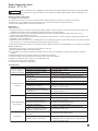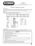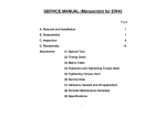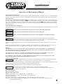
1
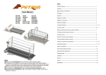
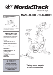
ZINKO
Hydraulic Jack
MODEL
ZTCL-30
Portable Tire Changing Lift
Toll Free: 1-800-579-8088 Web: www.zinko.com
Operation & Maintenance Manual
Important Receiving Instructions
Visually inspect all components for shipping damage. Shipping damage is NOT covered by warranty. If shipping damage
is found, notify carrier at once. The carrier is responsible for all repairs and replacement costs during product shipping.
Safety Information
Read and follow all instructions, warnings, cautions and carefully. Follow all safety precautions to avoid personal injury
or property damage during system operation. ZINKO is not responsible for damage or injury resulting from unsafe product
use, lack of maintenance, or incorrect product and/or system operation. Contact ZINKO when in doubt as to the safety
precautions and operations. Failure to comply with the following cautions and warnings could cause equipment damage
and personal injury.
Caution Remarks Used In This Manual
This manual, and the warning labels affixed to the lift itself, utilize the following signal words and definitions in all safety
instructions:
! DANGER
Failure to avoid the potential hazard could result in death or catastrophic bodily injury.
! WARNING
Failure to avoid the potential hazard could result in serious bodily injury.
! CAUTION
Failure to avoid the potential hazard could result in minor bodily injury or in damage to property.
Introduction
Never attempt to operate this lift unless you have first read and understand all of the operating
instructions and product warnings that are contained in this manual and on the warning labels affixed
to the lift itself. Failure to do so could result in serious bodily injury and property damage.
! WARNING
Contact your supplier immediately if you have any questions regarding the contents of this manual or of the warning
labels.
Always keep this manual nearby for convenient reference while operating this lift. Should either this manual or any of
the warning labels become lost or damaged, obtain replacement copies from your supplier immediately.
Warranty
WE WARRANT THIS LIFT TO THE ORIGINAL PURCHASER AGAINST DEFECTIVE MATERIALS OR WORKMANSHIP
FOR ONE YEAR FROM THE DATE OF INVOICE, PROVIDED THAT THIS LIFT IS USED IN ACCORDANCE WITH ALL
APPLICABLE INSTRUCTIONS AND WARNINGS.
OUR OBLIGATION IS LIMITED TO THE REPAIR OR REPLACEMENT OF DEFECTIVE COMPONENTS THAT ARE
RETURNED TO THE LOCAL LIFT SUPPLIER, FREIGHT PREPAID, WITH PROOF OF PURCHASE.
THIS WARRANTY SHALL NOT APPLY TO ANY DAMAGE RESULTING FROM THE ALTERATION, MISUSE, ABUSE,
UNAUTHORIZED REPAIR OR IMPROPER MAINTENANCE OF THIS LIFT.
Limited Function of This Lift
This lift was designed solely for the purpose of raising passenger vehicles and light pick-up trucks a
! WARNING few feet off the ground to facilitate the performance of tire, brake, oil, and bodywork.
Never attempt to use this lift to raise vans, trucks having extended wheelbases, or any other load that exceeds this lift's
rated capacity. This lift has not been designed to bear such unauthorized loads.
A loss of the load might therefore occur, which could result in serious bodily injury.
Never use this lift for under-the-vehicle work, to avoid the risk of being crushed.
Never work under any vehicle unless it has been provided with independent stable support, by
appropriate means, to prevent it from dropping.
! DANGER
General Specifications
Maximum Capacity: 6,000 lbs.
Minimum Table Height: 3-7/8"
Maximum Table Height: 37" for YMRL-60; 48" for YMRL-60HL
Electrical Requirement: 115VAC or 208-230VAC Single Phase, 60 Hz
Lifting Time: 30 seconds
Dual Safety Lock System: 1) Mechanical Safety Lock. 2) Hydraulic Velocity Fuse Valving.
Optional: 1) Higher Extension Rubber Pad Adapter (set of 4). 2) Adapter with Steel Flip-Up Flange (set of 4)
3) Portable Dolly Assembly.
Zinko Hydraulic Jack
Model: ZTCL-30
Parts Contents
Oil: 1 Can (1.5 Gallons)
Swing Arms: 4 pieces (when delivered, the swing arms are fully assembled with the tables)
Rubber Pad Adapters : 4 pieces
Stacking Adapters: 4 pieces
Plugs with Hole: 2 pieces
Hydraulic Hose: 12 Feet
Female Adapter (NPT) coupled with Hydraulic Hose: 1 piece
Safety Lock Release Lever: 1 piece (this lever is connected to the wire cable)
Safety Precautions
1. Any operator of this equipment shall read in detail this manual so as to prevent the occurrence of hazard.
2. The operator should know the function and operation method for every part this equipment.
3. The periodic inspection and inspection before operation shall be done according to this manual.
4. Do not operate this equipment any more, if you find any abnormal noise.
5. Do not operate this equipment beyond its maximum loading capacity.
Inspection Before Operation
Item
1.
Inspection
Inspect if up-down movement of lower Main and
Auxil-machine's platform is horizontal and smooth.
Method
Ocular Inspection
Treatment
Clean Up and Lubricate
2.
Inspect if the actions of safety pinion are normal
and up-down smoothly.
Ocular Inspection
Clean Up and Lubricate
3.
Inspect if the safety device is acting normally (if the
Ocular Inspection
safety pinion does not raise, the platform won't descend).
Clean Up
4.
Inspect hydraulic cylinder, oil pipe, and pipe joint to see
if any evidence of oil leaks, and inspect the motion of
safety device actuation wire.
Ocular Inspection
Cleaning and Re-fix
5.
Inspect motors pump motion, if sound is normal.
Listen to the Sound
Clean Up/Replace Parts
6.
Inspect lift parts and mechanism if they are normal.
Ocular Inspection
Clean Up/Lubricate/
Replace Parts
7.
Inspect if tension on the safety pinion and safety
device engage normally.
Ocular Inspection
and Action
Clean Up
Safety Warning
1) This lift must be operated and maintained in strict accordance with the procedures and warnings contained in
this manual, to avoid the risk of serious bodily injury.
2) The maximum lifting capacity is 6,000 Lbs., and any attempt to lift unauthorized loads in excess of that amount
could result in a loss of the load and serious bodily injury.
3) N0 modifications shall be made to this lift without the prior written consent of the manufacturer.
NEVER...
1. Attempt to use this lift for any purpose other than raising passenger vehicles and light pick-up trucks a few feet
off the ground to perform tire, brake, oil and bodywork.
2. Attempt to use this lift to raise vans, trucks with extended wheelbases, or any other loads that exceed its rated
capacity of 6,000 lbs.
3. Use this lift for any under-the-vehicle work.
4. Work under any vehicle unless it has first been provided with independent and stable support by appropriate
means, to prevent it from dropping.
5. Attempt to operate this lift unless you have had prior training and experience in the operation of this lift, and
you have also read and understood all of the operating and safety instructions contained in this manual.
6. Allow any untrained or unauthorized persons to operate this lift.
7. Operate this lift if any of the safety devices are inoperative.
8. Allow untrained or unauthorized persons to position vehicles on this lift.
9. Work on a raised vehicle unless the safety lock has first been engaged.
10. Operate this lift when bystanders are present at the site.
11. Attempt to operate this lift unless you have first read and understood the contents of the warning signs affixed
to this lift. Never remove warning signs from this lift.
12. Attempt to drive a vehicle onto this lift unless you have first confirmed that it is in its fully lowered position.
13. Attempt to block open or override the "OFF" control on the power unit.
Zinko Hydraulic Jack
Model: ZTCL-30
NEVER...
14.
15.
16.
17.
Raise a vehicle if someone is inside.
Permit anyone to ride on this lift while it is being raised or lowered.
Operate the power unit while any persons are working on a raised vehicle.
Attempt to service this lift while it is in a raised position. The loosening of any oil fitting could cause this lift to
fall. Always confirm that this lift is in its fully lowered position before attempting to service it.
18. Attempt to use adapters or attachments that were not provided by the manufacturer.
ALWAYS...
1.
2.
3.
4.
5.
Stand clear of this lift when it is being raised or lowered.
Confirm that there are no obstructions under this lift before lowering it.
Release th safety lock first before attempting to lower this lift.
Confirm that this lift is in its fully lowered position before backing a vehicle off it.
Inspect this lift carefully prior to its first use each day. Never attempt to operate it if any of its components
appear to be damaged or abnormal. Therefore, inspect this lift before each use for visual indications of damage.
6. Confirm that only genuine manufacturer's parts have been used in making repairs.
7. Confirm that the power cord has been disconnected, and that the power source has been safely locked out
prior to performing any maintenance on this lift.
8. Perform all scheduled visual inspections and preventative maintenance in a timely manner, and promptly
replace any damaged or worn components.
9. Keep the lift area clean, and free of any obstructions or debris.
10. Clean up any spilled grease and oil as quickly as possible. Keep the affixed warning label clean and legible.
Contact your supplier immediately for a free replacement if ever required.
11. Position the swing arms and adapters to provide unobstructed clearance before attempting to drive a vehicle
onto this lift. Never hit or run over the swing arms, as that could cause damage to this lift or the vehicle.
12. Position the adapters so that they will contact the vehicle at the lifting points recommended by the vehicle
manufacturer. First, raise this lift partially until the adapters make initial contact with the vehicle. After
confirming that they are making secure contact at the desired lifting points, raise this lift to desired working
height.
NOTE: The removal or installation of some vehicle components could result in a shift in the vehicle's center of gravity
and cause the vehicle to become unstable.
Before energizing this lift to test its operation following servicing, always confirm that all maintenance personnel
are standing clear of this lift.
When abnormalities arise, always stop this lift instantly with the "OFF" control on the power unit.
Positioning/Installation Instructions
Lift Positioning/Installation
1. This lift should only be installed and used on level concrete floors having a minimum thickness of five inches.
The concrete must have a minimum strength of 4,000 PSI, and must be aged at least 30 days.
2. Position the electric/hydraulic power unit so that a vehicle will never drive over the hydraulic hose, to prevent damage.
3. This lift is designed for indoor use only. The electric/hydraulic power unit is not waterproof and, if installed outdoors,
electric shock or damage to the electric/hydraulic power unit could occur.
Electric/Hydraulic Power Unit Installation
1. Firmly tighten the female adapter (NPT) at the end of the hydraulic hose to the male outlet-fitting on the hydraulic
power unit. Confirm that no foreign objects have entered the hydraulic hose.
2. Some hydraulic oil has been provided in each of the cylinders for anti-corrosion purposes during shipping, (APPROX.
100 cc IN EACH CYLINDER). Remove the temporary plug from each cylinder, drain all of the oil and then install the
replacement plugs that are equipped with safety valves.
3. Position the electric/hydraulic power unit well clear of this lift to assure that it will not obstruct the safe operation of
this lift. (For more detailed instructions, refer to the following procedures)
Installation Procedures
1. Positioning Machine - Check to ensure the ground is flat and rigid so as to prevent the accumulation of water and bad
environment, and then move lift to the place to be installed.
2. Install the Electric and Hydraulic System - 1) Place control Cabinet in suitable position. 2) Connect Ø ¼ piping to the
machine and control cabinet. 3) Install the control wiring of the safety pinion control circuit.
3. Connection of Power Supply - 1) Check to ensure that appropriate specification of power supply system. 2) Connect
15 Amp disconnecting device in front of the incoming terminal of machine. 3) The cable for the connection of
disconnecting device shall be 3.5 mm2.
Zinko Hydraulic Jack
Model: ZTCL-30
Installation Procedures (continued)
4. Inspection and Adjustment - 1) Turn on disconnecting device, and check if power indicator lights up. If no light,
the emergence stop may be engaged. Release it and check again. 2) Push "up" button to see if lift rises as control
command… 3) In case no raise for 3 phases machine, change the connection of any two phase conductors.
4) Check to ensure the lift could be raised to its extreme position. 5) During rising, check to ensure the normal
function of emergence stop.
5. Trial Run - 1) Drive car onto the lift and check if the car is placed at appropriate position. If in appropriate position
adjust it by moving foot plate and adjustment screws. 2) Push "up" button to the position in which the car is just
leaving the ground. 3) Inspect to ensure no interference with any other objects. 4) Raise lift to its extreme position,
and inspect to ensure no abnormal situation or leakage occurs. 5) Raise the safety pinion, and push the release valve
so as to check if lift could be descended smoothly. 6) Repeat #2 - #5 for a couple of times so as to ensure the lift
can be operated normally.
Operation Procedures
Inspection
It is essential that the following inspections of this lift be performed prior to its first use each day to assure safe
operation.
Component to be Inspected
Method and Treatment
•
•
•
•
•
•
•
•
•
•
•
•
Safety Lock Latch
Swing Arms and Adapters
All Hinge Points
Floors and Swing Arms
Wire Cable
Hydraulic Hose
Rollers and Shafts
Safety Lock Release
Hydraulic Pipes
All Welds
Hydraulic Oil
Safety Lock Control
Confirm
Confirm
Confirm
Confirm
Confirm
Confirm
Confirm
Confirm
Confirm
Confirm
Confirm
Confirm
that the lock "clicks" into position properly.
that all nuts and bolts are tight.
that all hinge points are greased.
that the floors are flat and the swing arms aren't cracked.
that cable isn't streched or rusty.
that there is no oil leakage.
that they have no cracks or other damage.
that the lock release disengages the safety latch.
the absence of cracks or leakage.
that there are no cracks.
that oil is clean and that the level is proper.
that the control is operating properly.
Purging Air From the Hydraulic System
Press the "UP" control on the power unit and raise this lift about 16". Then press the "DOWN" control
and lower this lift. Continue that process several times until all of the air is purged from the hydraulic system.
Mechanical Safety Lock Operating Test
• Actuate the safety lock release lever and confirm that the safety latch unlocks.
• Press the "UP" control on the power unit and raise this lift to its highest position, to confirm that the safety latch will
automatically "CLICK" into the safety lock position at both of the established sittings. When this lift reaches it's highest
position, immediately stop pressing the "UP" control to protect the motor.
• Actuate the safety lock release lever and press the "DOWN" control. Confirm that the safety latch unlocks and that
this lift will lower.
Positioning the Vehicle on the Lift
1. Fully lower this lift and drive the vehicle over it so that its center of gravity will be centered on this lift, for maximum
"LEFT TO RIGHT" stability, Neither its front nor rear wheel should contact this lift.
2. Position front wheel drive vehicles and light pick-up trucks slightly toward the rear of this lift, but position rear wheel
drive vehicles more toward the center of the lift, for maximum "FRONT TO REAR" stability.
3. Position the lift arm saddle adapters to contact the vehicle at the lifting points recommended by the vehicle
manufacturer.
4. If required, use stacking adapters to improve vehicle stability on this lift.
Raising A Vehicle
1. Press the "UP" control and raise the lift slowly until all of the saddle adapters contact the vehicle.
2. Visually confirm that each adapter is making full contact with the vehicle at the proper lifting point.
3. Raise this lift until the vehicle's wheels are slightly off the floor, and confirm that the vehicle is stably positioned.
4. Confirm that the safety lock is functioning properly.
Lowering A Vehicle
1. Before attempting to lower this lift, first raise it over 1" and actuate the safety lock release lever, to disengage the
safety lock.
2. Continue actuating the safety lock release lever while pressing the "DOWN" control, control, and lower this lift slowly
until the safety lock latch passes the lowerst safety lock position (AT A LIFT HEIGHT OF APPROX. 20 INCHES). In the
event of an emergency, cease actuating the safety lock release lever.
Zinko Hydraulic Jack
Model: ZTCL-30
When the safety lock is engaged, always raise the lift slightly before attempting to actuate the safety
lock release lever. This will protect the wire cable from becoming stretched, which could result in a
safety lock malfunction.
! CAUTION
Moving the Vehicle Off the Lift
1. Disengage the parking brake.
2. Confirm that this lift is in its fully lowered position, before attempting to back the vehicle off of the lift.
3. Remove all of the adapters from the swing arms, and push the swing arms inboard of this lift.
4. Slowly and carefully back the vehicle off of the lift.
Maintenance
Daily Inspections
1. Inspect this lift prior to its first use each day. Never operate it never operate it if any of its components appear to be
damaged or abnormal. Use only genuine manufacturer's parts in making repairs.
2. Confirm that the power cord has been disconnected, and that the power has been safely locked out, prior to
performing any maintenance on this lift.
3. Perform all scheduled visual inspections and preventative maintenance in a timely manner, and promptly replace any
damaged or worn components.
4. Never service this lift while it is in a raised position, the loosening of any oil fitting could cause this lift to fall. Confirm
that this lift is in its fully lowered position before attempting to service it.
5. Keep the lift area clean, and free of any obstructions or debris. Clean up any spilled grease or oil as quickly as possible.
Monthly Inspections
1. Re-tighten any screws or nuts that may be loose or worn out.
2. Keep lift greased to keep it moving smoothly.
3. Fix installation of piping with wrench and clean the oil if there is any leakage in hydraulic piping and/or hydraulic
cylinder.
4. Make sure buttons are mounted normally by cleaning them properly.
5. Clean and ensure the well connection of every wire in the control cabinet.
6. Replace the hydraulic oil or supply it to the sufficient level.
7. Inspect and replace where necessary.
8. Get rid of rust, lubricate it and paint it.
Troubleshooting
Problem
Cause
1. Leakage of hydraulic circuit.
Uneven Height of
2. Leakage of hydraulic cylinder.
Sides When Raised
3. Ground is not flat.
1. No power.
2. Emergency stop button is
pressed down.
3. Breakdown of "UP" button.
Lift Will Not Move 4. Breakdown of motor.
Upward
5. Breakdown of pump or
disconnection of connector.
6. Hydraulic oil loss or insufficient
hydraulic oil.
7. Breakdown of solenoid valve.
1. Insufficient hydraulic oil.
2. Inappropriate adjustment for the
pressure of terminal block.
Upward Movement 3. Throttle valve of main lift is
not open completely.
Slows Down
4. Leakage of piping system.
5. Block on the filter main and/or
auxilery cylinder connector.
1. Manually operated valve is not
opened.
Decent Fail
2. Safety pinion is not opened.
Solution
1. Change parts or repair.
2. Change part.
3. Move lift to level ground.
1. Switch on power and check power indicator.
2. Press the emergency stop button and turn right.
3. Repair or replace the "UP" button and turn right.
4. Repair or replace motor.
5. Repair or replace pump.
6. Supply hydraulic oil.
7. Repair or replace solenoid valve.
1. Supply hydraulic oil.
2. Increase the pressure setting of terminal block
by screwing clockwise.
3. Open the throttle valve of the
main lift counterclockwise.
4. Repair or replace parts of the piping system.
5. Disassemble and clean.
1. Push down the release valve.
2. Raise up the lift a short distance and release the
engagement of the safety pinion, and then push
down the release valve.
Zinko Hydraulic Jack
Model: ZTCL-30
Troubleshooting (continued)
Problem
Decent Movement
Too Slow
Rough Operation
Cause
1. Block in the "UP/DOWN" valve.
2. The flow rate for the return oil
circuit of "UP/DOWN" valve is
too small.
3. Block in the filter of main and/
or auxilery cylinder connector.
1. Breakdown or wear of parts.
Solution
1. Disassemble and clean.
2. Turn counterclockwise to an appropriate flow rate.
3. Disassemble and clean.
1. Repair or replace damaged/worn parts.
Parts Breakdown
Control Cabinet
and Pump
PART NO.
9240030-P
9240030-P
9240030-P
9240030-P
9240030-P
9240030-P
9240030-P
9240030-P
9240030-P
9240030-P
9240030-P
9240030-P
9240030-P
9240030-P
9240030-P
9240030-P
9240030-P
9240030-P
9240030-P
9240030-P
9240030-P
9240030-P
9240030-P
9240030-P
9240030-P
9240030-P
01
02
03
04
05
06
07
08
09
10
11
12
13
14
15
16
17
18
19
20
21
22
23
24
25
26
DESCRIPTION
"UP" button
Handle
Emergency stop
Power indicator
Control cabinet
"+" screw M6X12L
Spring washer
Washer
Fixing plate
Nut
Magnetic contactor
Fuse seat
Terminal
"+" screw M4X15L
Control cabinet cover
Moving wheel
Braking handle
"+" screw 3/16"
Control cabinet
Socket screw
Hydraulic connector
High pressure steel tube
Stop valve
Hydraulic connector
Hydraulic connector
Motor
PART NO.
9240030-P
9240030-P
9240030-P
9240030-P
9240030-P
9240030-P
9240030-P
9240030-P
9240030-P
9240030-P
9240030-P
9240030-P
9240030-P
9240030-P
9240030-P
9240030-P
9240030-P
9240030-P
9240030-P
9240030-P
9240030-P
9240030-P
9240030-P
9240030-P
9240030-P
9240030-P
27
28
29
30
31
32
33
34
35
36
37
38
39
40
41
42
43
44
45
46
47
48
49
50
51
RP
DESCRIPTION
Hydraulic connector
Packing ring
Plastic head
High pressure steel tube
Socket tube
Descent bar
H seat
Release valve
"+" screw M6X40L
Spring washer
Washer
Terminal block
Steel ball
Spring washer
Pressure adjusting screw
Hexagon nut
Oil cover
Oil tank
C ring
Nut
Hydraulic connector
Terminal block washer
O-ring
Bearing
Release valve
Repair Kit
Zinko Hydraulic Jack
Model: ZTCL-30
Parts Breakdown
REV 091307
Lift Table
PART NO.
9240030- 01
9240030- 02
9240030- 03
9240030- 04
9240030- RV
9240030- 06
9240030- 07
9240030- 08
9240030- 09
9240030- 10
9240030- 11
9240030- 12
9240030- 13
9240030- 14
9240030- 15
9240030- 16
9240030- 17
9240030- 18
9240030- 19
9240030- 20
9240030- 21
9240030- 22
9240030- 23
DESCRIPTION
Semi-round socket bolt
Foot plate
Foot mat bearing
Foot mat sliding seat
Washer
Big head screw
Shaft
Inner bushing
Du bushing
Inner knife arm
Moving wheel
Du bearing
Socket bolt
Screw cover
Press spring
Upper cover
Sliding arm
Locking Bar
Foot mat bearing seat
Pinion packing ring
Pinion
PART NO.
9240030- 24
9240030- 25
9240030- 26
9240030- 27
9240030- 28
9240030- 29
9240030- 30
9240030- 31
9240030- 32
9240030- 33
9240030- 34
9240030- 35
9240030- 36
9240030- 37
9240030- 38
9240030- 39
9240030- 40
9240030- 41
9240030- 42
9240030- 43
9240030- 44
9240030- 45
9240030- 46
9240030- RP
(909)989-9526
(909)989-1724
DESCRIPTION
Pinion seat
Pinion lock
Connection unit
Locking shaft
Safety pinion lock
Packing ring
Nut
Packing ring
Tension spring
Hexagon head bolt
Hexagon head bolt
Nut
External knife arm
Locking shaft
Washer
Du Bearing
Moving shaft
Bushing
Hexagon bolt
Spring washer
Locking shaft
Hydraulic cylinder
Du Bearing
Repair Kits