1
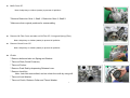
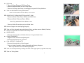
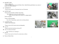
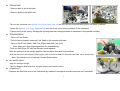
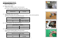
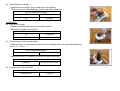
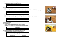
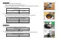
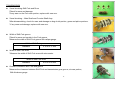
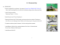
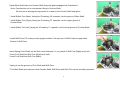
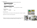
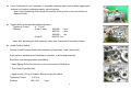
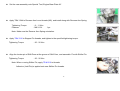
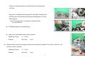
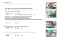
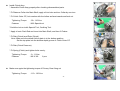
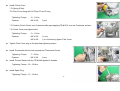
SERVICE MANUAL (Manuscript) for EW45
Page
A. Removal and Installation
1
B. Disassembly
1
C. Inspection
6
D. Reassembly
Attachment
14
(1) Special Tool
(2) Timing Chain
(3) Matrix Table
(4) Fasteners and Tightening Torque table
(5) Tightening Torque chart
(6) Service Data
(7) Adhesive, Sealant and Oil application
(8) Periodic Maintenance Schedule
(9) Specifications
1
A. Removal and Installation
Dinli to complete the section pertaining to the engine removal and the installation onto vehicle.
B. Disassembly
Set the engine assembly onto Special Tool; Engine Base Plate AY.
Take out Cover CP (Drive Chain) and Plate (Drive Chain).
Dinli to make
Arrangements for
The applicable photo
Operate Shift Pedal to engage the transmission gears.
Remove bolts and take out Fixing Plate, and then remove Sprocket 14T.
Remove Shift Pedal.
Remove Reverse Arm Lever (Reverse Lock).
Remove Carburetor.
Remove upper side banjo bolt (oil fitting) first, after that other bolts, and then take out Oil Delivery Pipe Assy.
Note: Pay attention not to lose total 6 cupper washer.
2
MAG Cover CP.
Note: Adopt tray or clothes (waste) to prevent oil pollution.
* Remove Reduction Gear 1, Shaft 1, Reduction Gear 2, Shaft 2.
* Make sure their original positions for reassembling.
Remove Oil Filter Cover and take out Oil Filter CP, O-ring and Spring (Filter).
Note: Adopt tray or clothes (waste) to prevent oil pollution.
Remove Clutch Cover CP.
Note: Adopt tray or clothes (waste) to prevent oil pollution.
Clutch
* Remove bolts and take out Spring and Washer.
* Take out Disk (Clutch Pressure).
* Take out Pusher.
* Remove Push Rod by depressing Release Lever.
* Remove Lock Nut.
Note: Lock Nut was caulked, and so unlock the caulk by using drill.
* Take out Lock Washer.
* Take out Clutch, Distance Collar and Thrust Washer.
3
Oil Pump
* Take out Snap Ring and Oil Pump Gear.
* Remove bolts and take out Oil Pump Case.
* Take out Oil Pump; feed Pump, Scavenging Pump and Oil Pump Shaft etc.
Take out Shift Shaft CP along with washer.
Note: Fit the washer onto the Shaft, not to lose it.
GUIDE PLATE, DRUM SHJIFTER and SHIFT CAM
* Remove Guide Plate, Drum Shifter and Shift Cam.
* Remove Guide Plate and Drum Shifter.
Note: Pay attention Drum Shifter is not
* Take out Shifter Pin and then pull out Shifter Cam.
Remove Stopper Arm and Spring (Stopper).
Take out Point (Neutral) along with Spring (Point), and then remove Switch (Position).
Remove nut and take out washer and Primary Gear.
HEAD COVER
* Remove bolts and take out Rubber Mounts, O-ring and Head Cover.
CHAIN TENSIONER
* Align the TDC, and remove adjusting bolt.
* Remove bolts and tale out Tensioner.
CAM SUPPORT, CAMSHAFTS
* Remove bolts and take out Cam Support
* Tank out intake Camshaft, exhaust Camshaft and Bearing Stoppers.
Note: Pay attention not to lose Bearing Stoppers.
Take out Crank Sprocket by holding the chain at the upper portion (cylinder head side).
Take out Timing Chain.
4
MAGNETO ASSY
* Remove flange nut.
* Take out Magneto Assy along with Starter Gear, Needle Bearing and Spacer, by means of
Special Tool; MAG Remover.
THERMOSTAT
* Remove bolts and take out Thermostat Cover and Thermostat.
WATER PUMP
* Remove bolts and take out Water Pump Case.
Note: Adopt tray to prevent coolant pollution.
Make sure the original (one) position of a cupper washer.
*Take out Impeller.
* Take out Sealing Washer.
Note: When reassembling, replace with new Sealing Washer.
CYLINDER HEAD
* Remove two (2) M6 bolts.
* Remove four (4) M11 bolts evenly and diagonally.
Lever CP.
* Remove pivot bolt and take out Lever CP.
Take out Cylinder and Gasket.
Note: Hold Piston not to damage it.
PISTON
* Take out Clip and pull out Piston Pin and then take out Piston.
Remove Starter Motor.
5
CRANKCASE
* Remove bolt on the clutch side.
* Remove bolts on the MAG side.
* Take out the crankcase from Special Tool; Engine Base Plate AY and set it with the clutch side facing up on the plastic containers.
* Attach the Special Tool; Case Separator Kit onto the clutch cover mating surface of the crankcase.
* Tighten two(2) bolts evenly, keeping the opening between mating surfaces of crankcase in the parallel condition.
TRANSMISSION
* Take out Fork Shafts.
* Pull out Spring located under the Fork Shaft on the counter shaft side.
* Take out Shift Fork (Main), Shift Fork (Right) and Shift Fork (Left).
Note: Make sure their original positions for reassembling.
* Take out Shift Drum CP with the Reverse Lock released
*With the case put un the upright position, take out Main Shat and Counter Shaft,
* With the case put in the original position again, take out Reverse Shaft CP (Reverse Idle Gear, collar, Washer etc.)
Note: Pay attention not to lose the Counter Shaft washer.
BALANCER GEAR
* Align the mating markings.
* Take out Balancer Shaft and Gear, by lightly tapping with plastic hammer.
CRANKSHAFT
* Depress the MAG side end of the Crankshaft by means of hand-press machine and take out Crankshaft.
6
C. Inspection
CYLINDER HEAD
Disassembling
(Note) Identify the original position of disassembled parts, with marking as necessary. Place them in order on the clean table.
* Remove Valve lifter and adjusting pad.
* While depressing Valve Spring with exclusive tool (Valve spring compressor),
take out Colette.
* Take out Spring Retainer, Spring (inner and outer), Seat (spring).
* Take out IN and EX Valve.
* Take out Valve (Seal).
Cylinder Head warpage
* Clean and remove carbon deposits from the surface. Never damage the surface when cleaning.
* Place the measuring block diagonally on the surface, and check with thickness gauge.
* If the result is out of specifications, replace with new Cylinder Head.
Cylinder Head warpage
Service Limit
0.05 mm
Inner diameter (ID) of Valve Guide
* Clean up the Valve Guide hole.
* Measure ID of Valve Guide at total 6 points; upper, middle and bottom positions and
X- and Y-directions, by means of dial caliper.
Service Limit of Valve Guide ID
IN
6.000 to 6.012 mm
EX
6.000 to 6.012 mm
7
INTAKE and EXHAUST VALVE
Valve Stem runout
*Remove carbon deposits.
Place on the V-block.
* Measure the marginal width of valve face portion.
*If the result is out of specifications, replace with new valve.
Valve Stem runout
Service Limit
0.03 mm
Outer diameter (OD) of Valve Stem
*Meastre OD of Valve Stem sliding portion at total 6 points; middle and lower positions
and X-and Y-directions, by means of micrometer.
Service Limit of Valve Guide OD
IN
5.950 to 5.965 mm
EX
5.945 to 5.960 mm
Clearance between Valve stem and Guide
Service Limit of Clearance
IN
0.15 mm
EX
0.15 mm
Width of Valve face
* Measure the marginal width of valve face portion.
* If the result is out of specifications, replace with new valve.
Service Limit of marginal width
IN
0.08 mm
EX
0.08 mm
8
Valve Spring free length
* Measure the free length of inner and outer Valve Spring.
* If the result is out of specifications, replace with Spring as a set.
Service Limit of free length
IN
38.0 mm
EX
39.9mm
CAMSHAFT
Cam profilw height
* Check for damage and ware on cam profile portion.
* Measure the height of cam profile.
Service Limit of cam profile height
IN
42.05 mm
EX
42.05 mm
Oil clearance at cam journal portion
* Measure the ID of cam journal portion with Cam Support fixed to the specified tightening
torque; 9 – 11 N-m.
ID of cam journal portion
Standard
25.000 to 25.021 mm
* Measure the OD of Camshaft journal portion with micrometer.
OD of Camshaft journal portion
Standard
24.964 to 24.963 mm
Oil clearance is ID minus OD.
Oil clearance at cam journal portion
Service Limit
0.10 mm
9
Viaual Checking
* Check for ware and damage on Cam Sprocket gear teeth.
* Check for ware and damage on decompression related parts.
* Check if decompression would be operated smoothly.
* If any parts would be damaged or worn, replace with new Camshaft Assy.
CYLINDER
Cylinder warpage
* Clean and remove carbon deposits from the surface. Never damage the surface when cleaning.
* Place the measuring block diagonally on the surface, and check with thickness gauge.
Cylinder warpage
Service Limit
0.05 mm
Cylinder bore
* Check for damage or ware on bore surface.
Measure the cylinder bore at total 6 positions; top, middle and bottom positions
and axial (Camshaft) and right angle directions.
Cylinder bore
Service Limit
94.000 to 94.020 mm
PISTON and PISTON PIN
Piston OD
* Check for ware and damage on the sliding surface.
* Measure OD of Piston at 11 mm distance from the bottom end in the right angle against Piston Pin
with micrometer.
Piston OD
Standard
93.955 to 93.970 mm
10
Clearance between Piston and Cylinder
* Clearance is Cylinder ID minus Piston OD.
Clearance between Piston and Cylinder
Service Limit
0.100 mm
ID of Piston hole for Pin
* Clean Piston hole for Pin.
* Measure ID in the up and down direction and the right angle direction with dial caliper gauge.
ID of Piston hole for Pin
Standard
23.001 to 23.007 mm
Piston Pin OD
* Check for ware and damage on the sliding surface.
* Measure OD at total 3 positions; both ends and middle position in the X- and Y-direction.
Piston Pin OD
Standard
22.996 to 23.000 mm
CONNECTING ROD
Small end ID
* Check for ware and damage on the sliding surface.
* Measure ID in the X- and Y-direction with caliper dial gauge.
Small end ID
Standard
23.007 to 23.020 mm
Clearance between small end ID and Piston Pin OD
* Clearance is small end ID minus Piston Pin OD.
Clearance between small end ID and
Piston Pin OD
Service Limit
0.05 mm
11
PISTON RINGS
Clearance between Piston Ring and groove
* Remove carbon deposits from Rings and grooves.
* Measure the clearance between Piston Ring and groove, by holding the Ring upwards
in the groove, with thickness gauge.
Service Limit of clearance between Piston
Ring and groove
Top
0.15 mm
Second
0.15 mm
Piston Ring gap (Opening)
* Insert Piston Ring into the lower portion of Cylinder horizontally by using Piston.
* Measure the Piston Ring gap (opening) with thickness gauge.
Service Limit of Piston Ring gap (Opening )
Top ring
0.7 mm
Second ring
0.8 mm
Oil ring (side rail)
1.0 mm
CRANKSHAFT
Runout
Set on the V-block and measure runout with dial gauge.
Crankshaft Runout
Service Limit
0.06 mm
Side-clearance at large end of Connecting Rod
* Measure the side-clearance at large end of Connecting Rod with thickness gauge.
Side-clearance at large end
Service Limit
0.65 mm
12
TIMING CHAIN
Chain Pitch
* Check for ware, damage and roller fallout.
* Place Chain on the flat table and pull with the 4.53 kg force and then
measure the length of 20 pitches.
Timing Chain Pitch (20 pitches)
Service Limit
13.7 mm
STARTER GEAR/ONE-WAY CLUTCH
Disassembly
* Remove One-way Clutch from Flywheel Assy.
Fastener ; M6×16L Bolt (socket head) 8 pcs.
CLUTCH
Visual checking – Plate and Disk
* Check for ware and damage.
* Check for movement of bearing.
* If any damage or excessive ware would be found, replace with new one as a set.
Visual checking – Release shaft and Push rod
* Check for ware and damage.
Width of friction material
* Measure the width of friction material with caliper gauge.
Width of friction materal
Service Limit
2.8 mm
(Note) Clutch Disk A and B are available. Clutch Disk B should be facing front side.
13
TRANSMISSION
Visual checking-Shift Fork and Drum
*Check for ware and damage.
*If any ware on the Fork craw portion, replace with new one.
Visual checking – Main Shaft and Counter Shaft Assy
*After disassembling, check for ware and damage on dug clutch portion, gears and spline portions.
* If any ware and damage, replace with new one.
Width of Shift Fork groove
*Check for ware and scratch in the Fork groove.
*Measure the width of Shift Fork groove with caliper gauge.
Width of Shift Fork groove
Standard
5.10 to 5.17 mm
Width of Shift Fork craw
* Measure the width of Shift Fork craw with micrometer.
Width of Shift Fork craw
Standard
4.93 to 5.00 mm
Clearance between Shift Fork and groove
*Measure the clearance between Shift Fork and transmission gear groove, at craw portion,
With thickness gauge.
14
D. Reassembly
CRANKCASE 1
* Press-fit crankshaft into crankcase 1 by means of Special Tool; CRANK ASSY TOOL KIT.
Note: Hold Connecting Rod not to strike the Crankcase mating surface while press fitting.
* Install 1/8 plug in position.
Tightening Torque : 9 -15 N-m
*Attach Reverse Arm CP onto Crankcase 1.
* Retain the Reverse Arm CP with washer and snap ring from the outside of Crankcase 1.
Note: Be sure not to damage oil seal. Make sure the snap ring is in the groove without fail.
* On plastic containers, place Crankcase 1 with the mating surface upwards.
* Install Balancer Shaft with the markings between Drive Gear of Crankshaft and
Driven Gear of Balancer Shaft aligned.
* Install Reverse Shaft CP.
15
*Install Main Shaft Assy and Counter Shaft Assy with gears engaged into Crankcase 1.
Note: Pay attention not to miss washer fitting to Counter Shaft.
Be sure not to damage the lip portion of oil seal by the Counter Shaft end spline.
* Install Shifter Fork (Main), facing the ID marking “M” upwards, into the groove of Main Shaft.
* Install Shifter Fork (Right), facing the ID marking “R” upwards, into the upper groove of
Counter Shaft.
* Install Shifter Fork (left), facing the ID marking “L” upwards, into the lower groove of Counter Shaft.
*Install Shift Drum CP in the pin side upright condition. Set each pin of Shift Forks into applicable
Groove of Shift Drum.
*Insert Spring (Fork Shaft) into the hole (Inner diameter; 11 mm) each of Shift Fork (Right) and (Left).
* Insert Fork Shaft into Shift Fork (Right) and (Left).
* Insert Fork Shaft into Shift Fork (Main).
* Apply oil into the grooves of Fork Shaft and Shift Drum.
* Turn Main Shaft and make sure that Counter Shaft, Shift Drum and Shift Fork can be smoothly operated.
16
CRANKCASE 2
* (When replacing Bearing with new one) Install Bearing Retainer Plates.
Stopper Plate for Main Shaft Bearing
Tightening Torque : 12 - 14 N-m
Fastener
:M6 Hex bolt
1 pcs.
Stopper Plate B for Shift Drum Bearing
Tightening Torque : 7 – 9 N-m
Fastener
: M6 Hex bolt
* Install Drain Plug.
Tightening Torque : 7 - 9 N-m
Fastener
: M16 Bolt
1 pcs. Apply TB #1316 to threads.
1 pcs.
*Fit Oil Strainer UN.
*On plastic containers, place Crankcase 2 with the mating surface to crankcase 1 upwards.
*Apply TB # 1215 evenly onto the mating surface.
* Adjust the convex position on the end surface of Water Pump Shaft to meet with
the groove on the end surface of Balancer Shaft (on Crankcase 1 side).
17
Cover Crankcase 2 over Crankcase 1, assemble cases by lightly and carefully tapping with
hummer to fit mating surfaces properly, without decline.
Note: Hold Connecting Rod to keep the position of the groove on the end surface of
Balancer Shaft.
Tighten bolts to the specified tightening torque.
Tightening Torque
: 9 - 11 N-m
Fastener
: (Case 1 side)
M6X40L
7 pcs.,
M6X75L
7 pcs.
M6X50L
1 pc.
(Case 2)
M6X75L 1 pc.
Note: After tightening all bolts securely, make sure Crankshaft is smoothly rotated.
Install Position Switch.
Caution: Install Position Switch after assembling Crankcase 1 and 2 without fail.
If the switch is installed onto Crankcase in advance, it will be depressed by
Shift Drum and damaged when assembling.
* Insert Spring (Point) into the hole on the end surface of Shift Drum.
* Then insert Point (Neutral).
* Apply oil onto O-ring of Position Switch and set the switch.
Tightening Torque
: 3-5 N-m
Fastener
:M5×20L
2 pcs.
18
Set the case assembly onto Special Tool; Engine Base Plate AY.
Apply TB # 1344 to Reverse Arm Lever threads (M6), and install along with Reverse Arm Spring.
Tightening Torque
Fastener
: 9 - 11 N-m
: M8 X 12L
1 pc.
Note: Make sure the Reverse Arm Spring orientation.
Apply TB #1316 to Stopper Pin threads, and tighten to the specified tightening torque.
Tightening Torque
: 20 - 26 N-m
Align the locator pin of Shift Drum at the groove of Shift Cam, and assemble. Fix with Shifter Pin.
Tightening Torque
: 20 - 26 N-m
Note: When re-using Shifter Pin, apply TB #1316 to threads.
Adhesive (LockTite) is applied onto new Shifter Pin threads.
19
Apply TB #1316 to M6 Stepped bolt threads, and fix Stopper Arm CP and Spring (Stopper) with
M6 Stepped bolt.
Tightening Torque : 9 - 11 N-m
Fastener
: M6 Stepped bolt 1 pc.
Note: Make sure the Spring (Stopper) orientation.
Assembly Oil Pump Assy as shown in the illustration in advance.
(1) Oil Pump Case 1
(2) Oil Pump Case 2
(3) Inner Rotor (Feed)
(4) Outer Rotor (Feed)
(5) Inner Rotor (Scavenge)
(6) Outer Rotor (Scavenge)
(7) Oil Pump Shaft
(8) Dowel Pin; 2 pcs.
*Insert shorter pin (φ3 X 15L) into the hole of Oil Pump Shaft, and then assemble with Inner Rotor (Scavenge).
* Set Pump Case 1 into Oil Pump Shaft.
* Insert another shorter pin (φ3 X 15L) into the hole of Oil Pump Shaft.
* Assemble Outer Rotor (Feed) and Inner Rotor (Feed) with Pump Case 2, and apply oil into rotor
* Set Oil Pump Shaft into Pump Case 2, fix Case 1 and 2 with two longer pins (φ3 X 19.8L).
*Fit Outer Rotor (Scavenge).
Install Oil Pump Assy.
Tightening Torque
Fastener
: 9 - 11 N-m
: M6 X 30L
3 pcs.
Note: Make sure the smooth rotation of Oil Pump shaft.
20
Assemble Drum Shifter and related parts.
Make sure the spring force and smooth operation by moving the ratchet pole with finger.
Install Drum Shifter along with Shifter Collar and Guide Plate onto Shift Cam.
Tightening Torque
: 9 - 11 N-m
Fastener
: M6 X 20L
2 pcs.
Fit Oil Pump Gear and adopt snap ring into the groove on Oil Pump Shaft end.
Insert Shift Shaft CP with Special Tool; Oil Seal Guide adopted.
Apply oil to Special Tool; Oil Seal Guide in advance.
Engage Stopper Pin and Shifter Collar into the groove of Shifter Lever.
Note: Be sure to fit washer onto Shift Shaft.
Take out Special Tool; Oil Seal Guide, temporally fit Shift Pedal CP and make sure gear is shifted properly.
Also make sure reverse locking operation.
21
Apply oil to O-ring and install Starter Motor in position.
Tightening Torque
: 9 - 11 N-m
Fastener
: M6 X 25L
2 pcs.
Fit two Pipe Knocks and set Cylinder Gasker.
Assemble and install Piston.
* Set Piston Rings into Piston grooves;
- Expander Ring into Oil Ring groove
-Second Ring, facing the marking upwards
-Top Ring, facing the marking upwards
* Make sure rings are smoothly moved and adjust the openings (gaps) at 120-degrees intervals.
* Fit new clip into the groove on one side and make sure of the clip fitting properly in the groove.
* Place Special Tool; Piston Support Plate.
* Insert Piston, with the marking on the top surface faced to magneto side, into cylinder.
*Apply oil to small end hole of Connection Rod, Piston Pin and hole. Then fit Piston Pin into Piston.
*Fit new clip into the groove on anther side and make sure the clip fitting properly in the groove.
Apply oil around Piston and Rings, and cylinder bore.
Install Cylinder by holding Rings by Special Tool; Ring Band.
Make sure of the smooth operation by turning Crankshaft, with Cylinder pressed down by hand
22
Install Chain Guide 1 onto Cylinder.
Assemble Cylinder Head as shown in the illustration;
(1) Seal-valve
(2) Intake Valve
(3) Exhaust Valve
(4) Valve Spring (Inner)
(5) Valve Spring (Outer)
(6) Spring Retainer
(7) Colette (Valve)
(8) Seat (Valve Spring)
; 4 pcs.
; 2 pcs.
; 2 pcs.
; 4 pcs.
; 4 pcs.
; 4 pcs.
; 8 pcs.
; 4 pcs.
* Press-fit Seal (Valve) by means of exclusive tool.
Note: Pay attention on the Seal (Valve) appearance.
Intake (IN) side --- Black
Exhaust (EX) side ---Green
*Fit Seat (Valve Spring) not to over-ride the step.
* Set Valve Spring (Inner), facing the green paint marking upwards.
* Set Valve Spring (Outer), facing the yellow paint marking upwards.
* Apply oil onto the shaft ends of IN and EX Valve, Valve Guide and Seal (Valve) and fit the valves into Cylinder Head.
Note: Keep the IN and EX valve fitting in the original position. Do not mix IN and EX valves.
* While depressing Valve Springs with exclusive tool, fit Spring Retainer and Colette onto valve shaft end.
Note: Make sure of Colette fitting securely to Valve Retainer.
Do not depress Valve Spring extremely.
*Fit Adjusting Pad and Valve Lifter.
Note: Keep Adjusting Pad and Valve Lifter fitting in the
Fit two pipe knocks and Head Gasket.
23
Install Cylinder Head.
* Apply oil to M11 bolts threads and washer, and then tighten them in the following procedure.
(1) Tighten to 30 N-m
(2) Tighten to 70 N-m
(3) Loosen by 180-degrees
(4) Loosen by 180-degrees
(5) Tighten to 35 N-m
(6) Turn by 80 to 90-degrees clockwise
(7) Turn by additional 80 to 90-degrees clockwise
Fastener
: M6 X 25L
* Tighten M6 bolts.
Tightening Torque
: 9 - 11 N-m
Fastener
: M6 X 40L
4 pcs.
Install Chain Lever with pivot bolt.
Tightening Torque
: 13.5 – 16.5 N-m
Fastener
2 pcs.
: M8 X 22.5L Pivot bolt
1 pcs.
Put Timing Chain from the Cylinder Head side and set in position
as shown in Attachment (2).
* Fit Crank Sprocket with the chamfer portion inside and
with each spline aligned
24
* Align the markings between Crank Sprocket and marking pale
of Chain.
* Apply oil to Camshafts attaching portion, and install Camshaft (IN)
and (EX) with Cam Sprocket marking and marking plate of Timing
Chain aligned.
Note: Decompression is furnished on Camshaft (EX).
Do not mixed up.
Fit Bearing Stopper onto Ball Bearing.
Apply oil to Cam Support and install in position.
Tightening Torque
: 9 - 11 N-m
Fastener
: M6 X 40L
8 pcs.
Depress Chain Tensioner plunger into the bottom possition by Special Tool; Chain Tensioner Tool
And then Install Tensioner.
Tightening Torque
: 9 - 11 N-m
Fastener
: M6 X 25L
2 pcs.
25
* Take out Special Tool and install bolt with Gasket (Aluminum).
Tightening Torque
Fastener
: 4.5 – 6 N-m
: M6 X 8L
1 pcs.
* Make sure of smooth operation by turning Crankshaft.
Adjust valve clearance with thickn gauge adopted at TDC position in the following procedures;
Valve Clearance (Cold condition)
IN; 0.15 +/- 0.05 mm
EX; 0.27 +/- 0.05 mm
* Temporally fit original Adjusting Pad, and check the valve clearance.
results and listed figures (3 digits).
* Select applicable Adjusting Pad and fit it in place with original one.
* Check again valve clearance and make sure it is within the specifications.
*If out of the specifications, repeat the procedures.
Fit One-way Valve.
Tightening Torque
: 15– 21 N-m
Note: Make sure One-way Valve Assy is placed in position and then fix plug.
Install Water Pump.
* Fic Impeller along with Seal Washer by means of
Special Tool; Wrench (Counter Shaft) adopted to Counter Shaft.
Tightening Torque
: 9– 11 N-m
*Fit Case along with Gasket.
Tightening Torque
: 9– 11 N-m
Fastener
: M6 X 25L
7 pcs.
Note: At the bottom (one) position, fit the cupper gasket without fail.
26
Install Flywheel.
* Fit Spacer with the chafer side inside onto Crankshaft on the MAG side.
* Apply TB #1306 and remove oil from the taper portion of Crankshaft.
* Fit Needle Bearing and apply grease. Not to apply grease onto the taper porion.
* Install One-way Clutch onto Flywheel.
Tightening Torque
Fastener
: 13-15 N-m
: M6 X 16L Adhesive (LockTite) applied bolt
7 pcs.
* Fit Starter Gear and make sure of smooth counterclockwise rotation.
* Apply TB #1306 and remove oil from taper hole of Flywheel.
* Fit Flywheel, apply oil to threads and retaining surface of M14 nut.
* Tighten the nut to the specified tightening torque, with Special Tool; Wrench (Crank Sprocket)
Adopted to Crankshaft for preventing rotation.
Tightening Torque
Fastener
: 150– 117 N-m
: M14 Nut
Install Primary Gear with the inside marking aligned to spline.
Tightening Torque
: 9– 11 N-m
Fastener
: M6 X 25L
7 pcs.
Fit Release Shaft along with Spring (Release) and Plate (Release) in position.
Tightening Torque
Fastener
: 9– 11 N-m
: M6 X 20L
1 pcs.
27
Install Clutch Assy.
* Assemble Clutch Assy properly after checking disassembled parts.
* Fit Distance Collar into Main Shaft, apply oil into hole and turn Collar by one-turn.
* Fit Cultch Outer CP, lock washer with the hollow surface inwards and lock nut.
Tightening Torque
Fastener
: 90– 110 N-m
: M18 Special nut
*Caulk the lock nut with Special Tool; Caulking Tool.
* Apply oil onto Push Rod and insert into Main Shaft, and then fit Pusher.
* Fit Disk (Clutch) and Plate (Clutch).
Note: Make sure the widest friction plate is in the bottom position.
Set the top plate into the shallow depth groove of Clutch Outer CP.
* Fit Disk (Clutch Pressure).
* Fit Spring (Clutch) and tighten bolts evenly.
Tightening Torque
Fastener
: 9– 11 N-m
: M6 X 36L
6 pcs.
Make sure again the tightening torque of Primary Gear fixing nut
Tightening Torque
: 110– 130 N-m
28
Install Clutch Cover.
* Fit Spring (Filter).
*Fit Filter Cover along with Oil Filter CP and O-ring.
Tightening Torque
: 9– 11 N-m
Fastener
: M6 X 25L
2 pcs.
* Fit Gasket (Clutch Cover) onto Crankcase after spot applying TB #1215 onto the Crankcase surface.
* Fit Clutch Cover and tighten bolts.
Tightening Torque
: 9– 11 N-m
Fastener
: M6 X 25L
M6 X 65L
11 pcs.
1 pc.=Commonly tighten Filter Cover
Tighten Filter Cover plug to the specified tightening torque.
Install Thermostat with the hole upward and Thermostat Coverl.
Tightening Torque
: 7– 9 N-m
Fastener
: M6 X 20L
2 pcs.
Install Thermo Switch with the TB #1344 applied to threads.
Tightening Torque : 32 – 38 N-m
Install Spark Plug.
Tightening Torque : 15 – 20 N-m
29
Install MAG Cover.
* Apply grease around Shaft 1 and 2, and fit Reduction Gear 1 and 2 in position correspondingly.
* Apply grease to gears.
* Fit Stator Coil into MAG Cover.
Tightening Torque
: 5.5– 6.5 N-m
Fastener
: M5 X 30L
3 pcs.
* Route the coil wiring along the groove and fix Pulsar Coil over the wiring.
** Fit Plug 1 and 2 (MAG Cover).
Tightening Torque
: (Plug 1) 10– 12 N-m
(Plug 2) 3– 5 N-m
Note: Make sure O-ring is attached onto Plug (MAG Cover).
Set the harness grommet into the groove.
* Fit Gasket (MAG Cover) onto Crankcase after spot applying TB #1215 onto the Crankcase surface.
*Fit MAG Cover and tighten bolts.
Tightening Torque
: 9– 11 N-m
Fastener
: M6 X 35L
11 pcs.
Fit Oil Delivery Pipe.
Tightening Torque
: 15– 21 N-m
Note: Fit gasket on both sides of banjo (fitting).
Set the rubber pipe in horizontal direction.
30
Make sure O-ring (Head Cover) and Chain Guide 2 are furnished
and fit Head Cover.
Fit rubb mount and tighten bolts.
Tightening Torque
: 9– 11 N-m
Install Adapter with convex portion upwards.
Tightening Torque
: 16– 20 N-m
Fastener
: M8 X 20L
2 pcs.
Install carburetor onto Adapter.
Set Adapter band screw with the screw head upwards on MAG side.
Tightening Torque
: M4 X 30L
1 pc.
Fit Shift Pedal with the marking aligned.
Tightening Torque
Fastener
: 9– 11 N-m
: M6X 25L
1 pc.
Apply grease onto front and rear surfaces of Sprocket 14T, and install it in position.
Apply grease to Counter ShaftJ sprocket, and install Ficing Plate over the sprocket,
Tightening Torque
Fastener
: 9– 11 N-m
: M6X 12L
2 pcs.
31