1
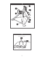
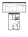
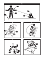
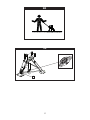
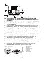
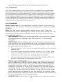
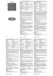
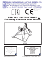
78
2105503
EN795: 1997
Class B
SPECIFIC INSTRUCTIONS 48
Swiveling Concrete Roof Anchor
NOTIFIED BODY:
No. 0086
BSI Product Services
Kitemark House
Mayland Ave
Hemel Hempstead
HP2 4SQ
UK
Form No:5902401 Rev A
8
NOTIFIED BODY:
No: 0321
SATRA Technology Centre
Wyndham Way
Telford Way
Kettering
Northants
NN16 8 SD
UK
9
© Copyright 2008, Capital Safety USA.
1
G
B
C
A
F
E
D
2
44.4 kN (10,000 lbs.)
A
B
22.2 kN
(5,000 lbs.)
2
3
2.4 m
1.8 m
1.8 m
4
A
B
3
5
C
E
D
B
A
6
7
D
B
A
A
C
C
B
E
8
9
B
A
B
A
C
4
10
11
A
5
1
9
10
3
4 5
7
78
EN See ‘Glossary’ in “General Instructions for Use and
Maintenance” for identification of numbered items in a
white box.
FR Voir Glossaire dans le mode d’emploi général (5902392)
pour l’identification des articles numérotés dans les
encadrés blancs.
DE Siehe „Glossar“ in der Allgemeinen Anleitung (5902392), um
nummerierte Teile in der weißen Schachtel zu identifizieren.
IT Per l’identificazione degli elementi numerati in una casella bianca
vedere il ‘Glossario’ nelle Istruzioni Generali (5902392).
ES Para identificar las partes numeradas dentro de un cuadro blanco,
consulte el apartado Glosario de las Instrucciones generales
(5902392).
PT Consulte o glossário nas “Instruções gerais” (5902392) para ver
a identificação dos elementos numerados numa caixa branca.
DA Se ”Glossar” under Generelle instruktioner (5902392) for
identifikation af nummererede dele i en hvid kasse.
NO Se Ordlisten i Generell instruksjon (5902392) for identifisering av
nummererte deler i en hvit boks.
FI Ks. Sanasto, osa Yleissohjeet (5902392), jossa on valkoisessa
ruudussa olevien numeroitujen kohtien nimet.
SV Se Ordlista under Allmänna instruktioner (5902392) för
identifiering av numrerade föremål i en vit ruta.
Label: RFID Tag
FR
I Étiquette sécurité
DE
i-Safe-Etikett
IT
I Etichetta di sicurezza
ES
Etiqueta I Safe
PT
Etiqueta I Safe
DA
I Sikkerhedsmærke
NO
I Sikkerhetsmerke
FI
I Safe -lipuke
SV
Etiqueta I Safe
6
labeling: iSafe™ Label
1
1.
1.
1.
1.
1.
1.
1.
1.
1.
This product is i-Safe enabled and contains an
electronic tag that can be read by compatible
readers--providing inspection logs, inventory
management and other safety information.
Ce produit peut être activé i-Safe et il contient
une étiquette électronique pouvant être lue par
des lecteurs compatibles, à condition de fournir
les historiques d’inspection, la gestion des
inventaires et autres informations de sécurité.
Dieses Produkt ist i-Safe-fähig und enthält ein
elektronisches Etikett das von kompatiblen
Lesegeräten ausgelesen werden kann und bietet so Inspektionsprotokolle,
Bestandsmanagement und andere
Sicherheitsinformationen.
Questo prodotto è abilitato i-Safe e contiene
un’etichetta elettronica facilmente leggibile da
dispositivi di lettura compatibili al fine di fornire i
verbali di collaudo, nonché istruzioni di gestione
dell’inventario e altri dati di sicurezza.
Este producto cuenta con la cobertura i-Safe y
contiene una etiqueta electrónica que puede ser
leída por lectores compatibles, que facilita los
historiales de inspección, el control de inventario,
así como otra información relativa a la seguridad.
O produto contém a funcionalidade i-Safe bem
como uma etiqueta electrónica que pode ser lida
por leitores compatíveis – apresentando historial
de inspecções, gestão do inventário e outras
informações de segurança.
Dette produkt er i-Safe aktiveret og
indeholder en elektronisk etiket, som kan
aflæses af kompatible aflæsere--den giver
inspektions logbøger, lagerstyrelse og anden
sikkerhedsinformation.
Dette produktet er i-Safe-aktivert og
innholder en elektronisk tagg som kan leses
ved hjelp av kompatible leseenheter - som
gir inspeksjonslogger, lagerstyring og annen
sikkerhetsinformasjon.
Tämä tuote on varustettu i-Safe-toiminnolla
Label: RFID Tag
FR
Étiquetage : étiquette i-Safe™
DE
Etiketten: iSafe™-Etikett
IT
Etichettatura: Etichetta i-Safe™
ES
Etiquetado: Etiqueta iSafe™
PT
Etiquetagem: etiqueta iSafe™
DA
Mærkning: i-Safe™ mærkat
NO
Merking: i-Safe™-merke
FI
Merkinnät: i-Safe™-tarra
SW
Etikett: i-Safe™-etikett
1.
ja se sisältää elektronisen lipukkeen, joka on
luettavissa yhteensopivilla lukulaitteilla. Tämä
mahdollistaa tarkastuslokit, varastonhallinnan ja
turvallisuustietojen tarkistuksen.
Denna produkt är i-Safe-aktiverad och innehåller
en elektroniskt märkning som kan avläsas
av kompatibla avläsare--som tillhandahåller
inspektionsloggböcker, inventariehantering och
annan säkerhetsinformation.
FR
Étiquette : étiquette RFID
DE
Etikett: RFID-Tag
IT
Etichetta: Tag RFID
ES
Etiqueta: Etiqueta RFID
PT
Etiquetagem: etiqueta RFID
DA
Mærkat: RFID-mærkat
NO
Merke: RFID-etikett
FI
Merkintä: RFID-tarra
SV
Etikett: RFID-märke
7
GB
SPECIFIC instructions - Swiveling Concrete Roof Anchor.
1.0 Description/Purpose
The Capital Safety Swiveling Concrete Roof Anchor includes (see Figure
1) tripod base (1A), swivel head (1B), ratchet buckle (1C), and web
assembly (1D) including the web strap (1E),web guide (1F) and roller
(1G). The swivel head is designed for installation of a Capital Safety
Ultra-Lok® model self retracting lifeline (SRL). The tripod base allows
installation to a precast concrete anchorage, such as a lifting eye.
The anchor may be used as part of a personal fall arrest system
(PFAS). Do not hang, lift or support tools or equipment from these roof
anchors or attach guy lines for antennas, phone lines, etc.
warning: See General Instructions for Use and Maintenance
section 1.1 and 1.3, 1.4 and 1.12.
IMPORTANT: If you have questions on the use, care, or suitability
for use of this equipment, contact Capital Safety. This instruction
manual is intended to be used in conjunction with the instruction
manuals supplied with each system component mentioned below, if
applicable. If an instruction was not supplied with the purchase of
that component, contact Capital Safety immediately.
2.0 requirements
The following application limitations must be recognized and
considered before using this product:
• CAPACITY: The roof anchor is designed for use by one person
with a personal fall arrest system (PFAS).
• PERSONAL FALL ARREST SYSTEM: The swiveling roof anchor
is designed to be used in conjunction with the Capital Safety
Ultra-Lok® SRL model 3504500, but may also be used with
models 3504430 and 3504450. Other PFAS’s used with this roof
anchor must meet CE requirements. PFAS’s incorporating a full
body harness must be capable of arresting a worker’s fall with
a maximum arresting force of no greater than 6kN (1351 lbs.)
(EN363) and limit the free fall distance to 4 m (13 ft.) or less.
• STRUCTURE: This anchorage connector is intended to be installed
on concrete structures. The anchorage to which the roof anchor is
installed must meet minimum strength(s) as given below for the
applications selected:
• Fall Arrest: The loads applied to the roof anchor from personal
fall arrest systems are magnified by the design of the roof
anchor. See Figure 2. The Concrete Swiveling Roof Anchor
requires anchorages that are able to support 44.4kN (10,000
lbs.) in a vertical direction (2A) and 22.2kN (5,000 lbs.)
8
horizontally (2B) for fall arrest applications.
• Restraint: The loads applied to the roof anchor from
personal fall arrest systems are magnified by the design
of the roof anchor. The Concrete Swiveling Roof Anchor
requires anchorages that are able to support 2722 kg
(6,000 lbs.) for restraint applications in a vertical (2A)
position and 1361 kg. (3000 lbs.) in a horizontal position.
See Figure 2.
Anchorages used for attachment of personal fall arrest systems
(PFAS) shall be independent of any anchorage being used to
support or suspend platforms.
Consult Capital Safety before using this swiveling anchor on any
other applications.
• LOCKING SPEED OF SRL: Situations which do not allow for an
unobstructed fall path should be avoided. Working in very confined
or cramped spaces may not allow the body to reach sufficient
speed to cause the SRL to lock should a fall occur. Working on
slowly shifting material such as loose shingles may not allow
enough speed build-up to cause the SRL to lock. A similar situation
may occur on low pitched roofs where a worker may slide instead
of fall. A clear path is needed to assure positive locking of the SRL.
•
ENVIRONMENTAL HAZARDS: Use of this equipment where
environmental hazards exist may require additional precautions to
reduce the possibility of injury to the user or damage to the equipment. Hazards may include, but are not limited to:
• Corrosion: Use near sea water or other corrosive environments
may require more frequent inspections or servicing
(replacement) to assure corrosion damage is not affecting the
performance of the product.
• Chemicals: Solutions containing acids, alkali, or other caustic
chemicals, especially at elevated temperatures may cause
damage to this equipment. Consult Capital Safety if doubts
exists concerning installing this equipment where chemical
hazards are present.
• Electrical: Do not install the roof anchor where it or the user
may come into contact with electrical power lines.
•
COMPATIBILITY OF COMPONENTS: This equipment is designed
for use with Capital Safety approved components and subsystems
only. See also General Instructions for Use and Maintenance Section 1.12.
•
COMPATIBILITY OF CONNECTORS: Connectors (hooks, carabiners, D-rings) must be capable of supporting at least 22 kN (5000
lbs.). Connectors must be compatible with the anchorage and
other system components and meet EN362 standards. See also
9
General Instructions for Use and Maintenance Section 5.
3.0 Training
It is the responsibility of the users of this equipment to understand
these instructions, and to be trained in the correct installation, use,
and maintenance of this equipment. These individuals must be aware
of the operating characteristics, application limits and consequences
of improper installation or use of this equipment. This user manual is
not a substitute for a training program. Training must be provided on
a periodic basis to ensure proficiency of the users. See also General
Instructions for Use and Maintenance 1.1.
4.0 planning
Before each use of this equipment, carefully inspect it according to
section 7.0 of this manual. Do not use if inspection reveals an unsafe
condition.
Plan your fall arrest system before starting your work. Take into
consideration factors affecting your safety at any time during use. The
following list gives some important points you must consider when
planning your system:
•
ANCHORAGE: Select an anchorage point that is rigid and capable
of supporting the required loads. See section 2.0 “Anchorage
Strength.”
•
Site Plan: Before starting the roof construction, plan where the
roof anchor(s) will be installed and when, during the construction
process, they may be used. The following are guide lines on locating roof anchors (see Figure 3):
• The roof anchor is for use in an upright position on a horizontal
surface only.
• The roof anchor should be located at least 1.8 m (6 ft.) away
from any leading edge. On very small roof areas, locate the
roof anchor as far from the leading edge as possible.
• Do not leave the roof anchor permanently installed. The roof
anchor is designed for temporary use only.
•
TOTAL FALL DISTANCE: Should a fall occur, there must be sufficient clearance in the fall area to arrest the fall before striking
the ground or other object. The total fall distance is the distance
measured from the onset of a fall to the point where the fall is
arrested. A number of factors can influence the total fall distance
including; user’s weight, anchorage location relative to the fall
(swing fall), body support with sliding D-ring, and the type of fall
arrest equipment you attach to the roof anchor. For specific clearance requirements read and follow the manufacturer’s instructions
for your subsystem fall arrest equipment.
•
SWING FALLS: See Figure 4. Swing falls occur when the anchor10
age point is not directly above the point where a fall occurs. The
force of striking an object while swinging (horizontal speed of the
user due to the pendulum affect) can be great and may cause
serious injury. Swing falls can be minimized by working as directly
below the anchorage point as possible. In a swing fall situation,
the total vertical fall distance of the user will be greater than if
the user had fallen vertically directly below the anchorage point.
The user must therefore account for an increase in the total free
fall distance and the area needed to safely arrest the fall. See also
General Instructions for Use and Maintenance Section 1.10.
The SRL will activate (lock-up) regardless of it’s orientation and
location relative to the user’s position. Do not captivate the lifeline
of an SRL, it may affect the performance of its braking. If a swing
fall hazard exists in your application, contact Capital Safety before
proceeding.
•
SHARP EDGES: Avoid working where the connecting subsystem
(i.e. SRL, full body harness, lanyard, lifeline, etc.) or other system
components will be in contact with, or abrade against unprotected
sharp edges. See Figure 5. If working with the roof anchor (5A)
near sharp edges (5B) is unavoidable, protection against cutting
must be provided by using a heavy pad or other means over the
exposed sharp edge. If you are not using the Leading Edge SRL
(PN 3504500), it is recommended that an EN 355 compliant energy absorber (5C) (PN 1220362) be installed in-line between the
harness (5D) and the self retracting lifeline (5E) to further protect
the worker. Compatibility and total fall distance issues must be
considered if this is done. Contact Capital Safety before using inline energy absorbing components or lanyards with self retracting
lifelines.
•
RESCUE: See General Instructions for Use and Maintenance section 1.6.
•
AFTER A FALL: See General Instructions for Use and Maintenance
section 1.2.
•
OTHER CONSIDERATIONS: Avoid working where your line may
cross or tangle with that of another worker or another object. Do
not allow the lifeline to pass under arms or between legs. Never
clamp, knot or otherwise prevent the lifeline from retracting or being taut, avoid slack line. Do not lengthen the SRL by connecting a
lanyard or similar component without consulting Capital Safety.
5.0 INSTALLATION
•
Roof anchor installation: Roof anchors must be installed
in accordance with the Section 4 “Site Plan.” Site work rules must
be followed regarding when an installed roof anchor is ready for
use (i.e. properly braced, etc.).
Step 1: Position the roof anchor over an anchorage capable of
withstanding the loads (see Section 2 “Anchorage Strength”).
11
Step 2: Ensure the shackle (6A) attached to the ratchet buckle
is positioned over the lug (6B), and the pin (6C) is in place. See
Figure 6.
Step 3: In Figure 1, the ratchet strap (1E) must pass through
the black plastic web guide (1F) built into the roof anchor (1A)
and over the roller (1G) as the strap exits the top member of the
tripod. In Figure 7, the strap must also pass through the center of
the ratchet buckle hub (7A). To release the ratchet strap (7B), pull
the lever (7C) on the ratchet handle and move the ratchet buckle
handle to the “full up” position (7D).
Step 4: Pull out as much of the strap as necessary to connect the
hook to the anchorage (8A). Ensure the latch on the hook fully
closes over the anchorage (8B). Do not use on anchorages that
load only the tip of the hook or side load the hook. Do not use on
anchorages that prevent the hook latch from closing. The tripod
must straddle the anchor, i.e., the anchor must be inside the tripod
legs. See Figure 8. The diameter of the anchorage cross section
(8C) must be less than 25.4 mm (1 in.).
ADJUSTMENT: See Figure 7 to remove slack in the ratchet
strap. Pull the lever on the ratchet handle and rotate the handle
downward (7E). With the handle in the open position (7D),
release the lever (7C) and continue to rotate the handle down.
The ratchet mechanism will allow the handle to take up more
slack with each upward rotation. Continue the ratchet movement
until the strap is taut. Lock the ratchet strap by returning the
ratchet buckle handle to the full down position before use (7E).
Ensure the ratchet buckle remains in the full down working
position during use.
•
INSTALLING THE SRL: In Figure 9, the SRL mounts to the swiveling roof anchor with two 9.5 mm (3/8 in.) bolts (9A) and nylon
insert nuts (9B). See SRL manufacturer’s instructions for use.
REMOVAL: The roof anchor is a temporary anchor. To remove it,
pull the lever on the ratchet handle (7C) and rotate the handle
to the full up position (7D). See Figure 7. When the lever is
released it will snap into a locked position (7E). The center hub
(7A) will then rotate freely and the ratchet strap (7B) may be
pulled out to create enough slack for the hook to be removed
from the anchor.
• BODY SUPPORT: When using the Swiveling Concrete Roof Anchor,
it is recommended that a full body harness be worn. For general
fall protection use, connect to the D-ring on the back between the
shoulders (dorsal D-ring).
12
warning: Body belts are not allowed for free fall situations.
Body belts increase the risk of injury during fall arrest in
comparison to a full body harness. Limited suspension time
and the potential for improperly wearing a body belt may result
in added danger to the user’s health. See also General
Instructions for Use and Maintenance section 2.0
• CONNECTING TO THE Roof anchor: Figure 10 illustrates
the proper connection of typical fall arrest equipment to the roof
anchor. Always protect the lifeline from abrading against sharp or
abrasive surfaces on the roof. Make sure all the connections are
compatible in size, shape and strength. Never connect more than
one personal protective system to any single roof anchor at a time.
• CONNECTING THE SRL: Connection to the installed roof anchor
is made by attaching the self locking snap hook at the end of the
Ultra-Lok’s® lifeline to the back dorsal D-ring of the user’s full body
harness. When connecting, make sure the connecting hook is fully
closed and locked. Review section 4.0 if using an SRL near sharp
edges.
6.0 USE
Once attached to the roof anchor, the worker is free to move about
within the recommended working areas.
•
SRL: Should a fall occur, a speed sensing brake system will activate, stopping the fall and absorbing much of the energy created.
Sudden or quick movements should be avoided during the normal
work operation since this may cause the SRL to lock-up.
NOTE: This series of SRL’s incorporates a brake system with a
cam rocker brake engagement that creates an audible indicator
(clicking sound) which informs the user that the brake pawl system
is working properly. For further information on the Ultra-Lok® SRL,
refer to the manufacturer’s instruction manual.
7.0 Inspection
Before each use, visually inspect the roof anchor per the steps listed
below.
important: See General Instructions for Use and Maintenance 1.2
regarding equipment that sustains a fall.
Record inspection results in the Periodic Examination and Repair
History Log at the end of this instruction, or use the i-Safe™ inspection
web portal to maintain your inspection records. See Figure 5. If you
are a first-time user, contact Capital Safety, 1-800-328-6146 or if you
have already registered, go to: www.capitalsafety.com/isafe.html.
Follow the instructions provided with your i-Safe handheld reader or on
13
the web portal to transfer your data to your web log.
warning: Extreme working conditions (harsh environment,
prolonged use, etc.) may require increased frequency of inspections.
• INSPECTION POINTS: (Refer to manufacturer’s instruction
supplied with each system component for inspection procedures)
•
Inspect the roof anchor for physical damage. Look carefully for
any signs of cracks, dents or deformities in the metal.
•
Inspect the roof anchor for signs of excessive corrosion. Make
certain the anchor swivels 360° properly and if applicable that
the Ultra-Lok® SRL is attached to the anchor correctly.
•
Inspect each system component or subsystem (i.e. SRL,
full body harness, lanyard, lifeline, etc.) per associated
manufacturer’s instructions.
•
Inspect the webbing material. It must be free of frayed, cut,
or broken fibers. Check for tears, abrasions, mold, burns,
or discoloration, etc. The webbing must be free of knots,
excessive soiling, heavy paint buildup, and rust staining. Check
for chemical or heat damage indicated by brown, discolored,
or brittle areas. Check for ultraviolet damage indicated by
discoloration and the presence of splinters or slivers on the
webbing surface. All of the above factors are known to reduce
webbing strength. Damaged or questionable webbing should
be replaced. Inspect stitching for pulled or cut stitches.
•
Inspect the web guide for deformation or cracks. The web
guide prevents the web from abrading against the steel tubing.
•
Inspect the hook for distortion, sharp edges, burrs, cracks,
worn parts or corrosion. Ensure the hook works properly. The
hook gate must move freely and lock upon closing.
8.0 Product life
As long as the Concrete Swiveling Roof Anchor passes inspection by a
competent person1, it may remain in service. See General Instructions
for Use and Maintenance Section 1.16 for warranty information.
9.0 maintenance/storage/Transport
•
Maintenance: Clean the swivelling tripod anchor with a mild
soap detergent solution. Excessive build-up of dirt, tar, etc. may
prevent the anchor from working properly. A small amount of oil or
grease can be applied to the anchor to help the swiveling action. If
you have any questions concerning the condition of your roof anchor, or have any doubt about putting it into service, contact Capi-
1 Competent Person: An individual who is knowledgeable of a manufacturer’s recommendations, instructions, and manufactured component who is capable of identifying existing and predictable hazards in
proper selection, use, and maintenance of fall protection
14
tal Safety immediately. Refer to the manufacturer’s instructions
supplied with each system component for maintenance, servicing,
and storage procedures.
•
Storage: See General Instructions for Use and Maintenance Section 3.3.
•
transport: See General Instructions for Use and Maintenance
Section 3.4.
10. Servicing
Additional maintenance and servicing procedures (i.e. replacement
parts) must be completed by a factory authorized service center.
important: Only Capital Safety or parties authorized in writing
may make repairs to this equipment.
11.0
SPECIFICATIONS
component
material
Tripod Base
Carbon Steel
Swivel Head
Carbon Steel
Webbing
Polyester
Rachet Web Hook
Forged Steel
FINISH: Black E-coat paint and zinc-plating
WEIGHT: 15 kg (33 lbs.) (without SRL)
SIZE: 66 cm x 66 cm x 61 cm (26 in. x 26 in. x 24 in.)
CAPACITY: One person
MINIMUM BREAKING STRENGTH: 22.2 kN (5,000 lbs.)
12.0 LABELING
Labels should be securely attached to the tripod anchor and fully
legible. See labels.
15