1
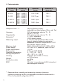
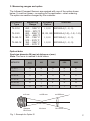
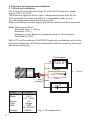
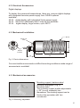
-32 °C to 2500 °C
THE INTELLIGENT AND PRECISE 2-WIRE SERIES
INFRARED COMPACT SENSORS
TL-S, TL-GA
USER MANUAL
NON-CONTACT T EMPERATURE MEASUREMENT - WORLDWIDE
2. Technical data
Pyrometer
Type
TL-S-18
TL-S-25
TL-GA-13
TL-GA-18
Measuring
range
650
1202
800
1472
300
572
350
662
... 1800 °C
... 3272 °F
... 2500 °C
... 4532 °F
... 1300 °C
... 2372 °F
... 1800 °C
... 3272 °F
Response time t 901):
Accuracy:
Repeatability:
Emissivity1):
Measuring output:
Maximum load:
Power supply:
Power consumption:
Safty system:
Operating temperature:
Storage temperature:
Housing:
Weight:
Connection cable:
EMC:
1)
1
Spectral
range
Distance to
Spot size
0.8-1.1 µm
100 : 1
0.8-1.1 µm
150 : 1
1.45-1.8 µm
100 : 1
1.45-1.8 µm
100 : 1
250 ms (Factory preset)
(adjustable in steps between 20ms and 10s)
0.5% of measuring value in °C + 1K
(at 23°C; 73.4 °F)
0.5% of measuring value in °C + 1K
5...100%, adjustable
(100% factory preset)
4...20 mA, load independent DC current,
linear to selected measuring subrange
Attention: At ambient temperatures > 75°C
the output is fixed to 3.9 mA!
700 W (24 V); 400 W (18 V); 1000 W (30 V)
24 V dc ± 25 %, stabilized, ripple <50 mV!
£1.5 VA
IP 65, acc. DIN 40 050
0 ... 70°C; 32 ... 158 °F
-20 ... 70°C; -4 ... 158 °F
Stainless steel Æ M40 x 1.5 mm,
ca.120 mm long
ca. 450 g
2.5 m
CE-Label in accordance with EU rules about
electromagnetic immunity
Response time, emissivity and measuring subrange (minimum
measuring subrange is 50 K) are adjustable via service-interface with a
PC or the handheld configurator HP 03.
3. Measuring ranges and optics
The Infrared-Compact-Sensors are equiped with one of the optics shown
below. It must be chosen - according to the application - when ordering.
The optics can not be changed by the customer.
Pyrometer
Type
TL-S-18
TL-S-25
TL-GA-13
TL-GA-18
Measuring
Range
Available
Optics
OrderNo.
I, II, III
650 ... 1800 °C
1202 ... 3272 °F
800 ... 2500 °C IS, IIS, IIIS
1472 ... 4532 °F
I, II, III
300 ... 1300 °C
572 ... 2372 °F
I, II, III
350 ... 1800 °C
662 ... 3272 °F
IK21800-4(-1, -2, -3)
IK22500-4(-1-S), -1-S, -1-S)
IK31300-4(-1, -2, -3)
IK31800-4(-1, -2, -3)
Optical data:
Spot size diameter M (mm) at distance a (mm)
Note: The focus is marked in bold letters.
OPTICSTYP
a=0
600
1000
1500
2000
(Aperture)
OPTICS I
13
6
15
26
36
OPTICS II
16
10
9
15
22
OPTICS III
17
13
11
11
17
OPTICS IS
13
4
12
23
34
OPTICS IIS
16
7
5
12
19
OPTICS IIIS
17
10
7
7
14
a=0 mm
a=600 mm
a=1000 mm
Aperture
M=13 mm
M=4 mm
M=12 mm
Fig. 1: Example for Optics IS
2
4. Electrical and mechanical installation
4.1. Electrical installation
The Infrared Compact Sensor series TL-S and TL-GA requires a power
supply of 24 V dc ± 25%.
The maximum ripple on the dc supply voltage must be less than 50 mV.
If the pyrometer has been connected it is immediately ready for use.
For wire assignment please see drawing below.
When connecting the power supply, the polarity must be correctly observed.
Note: Factory presettings:
Response time t 90 : 250 ms
Emissivity: 100 %
Measuring range: Maximum measuring range of the instrument
Peak Memory: OFF
With a PC and the software IP-SERVICE (optionally available) as well as the
handheld configurator HP 03 these parameters and the measuring subrange
can be set individually.
Digital display
+ 723,0°C brown
+
grey
(screen)
orange
Power supply LED 5 ... 30 V DC +
red
black
Power supply
24 V DC
+ -
Color
Function
Black
+24 V
(18 ... 30 V)
0V
Screen
LED
+5...30 V DC
LED 0 V
Brown
Grey
Red
Orange
3
Fig. 2: Wire assignment
4 … 20 mA
4.2. Electrical Accessories
Digital displays
To display the measured temperatures there are variours digital displays
with integrated two-wire power supply from CALEX optional
available:.
ID 50 digital display with integrated 2-wire power supply
ID 52 like ID 50, additionally with 2 internal limit switches
ID 54 digital display, large version, up to 500°C
4.3. Mechanical Installation:
SW 46
M40x1,5
Setup port
cover
Service
interface
74,5
30
~25
113
Fig. 3: Device dimensions
For more hostile environments or difficult mounting conditions a wide range of
accessories is available!
4.3. Mechanical accessories
Mounting support, stainless steel
Mounting, adjustable, (Fig. 4)
Mounting, fixed
The mounting support enable adjustments
(± 45°) in one, respectivly two
dimensions.The monting support can be
fixed on the pyrometer with two
counternuts.
Fig. 4: Mounting, adjustable
4
Stainless steel air purge unit
Standard air purge unit
The air purge unit protects the lens of your pyrometer even in rough
environments against dust, humidity or other suspended matters. The air flow
rate is about 25 to 30l/min at a pressure of 0.2 to 0.5 bar.
Cooling jacket, stainless steel
(air- or watercooling)
The stainless steel housing protects the instrument in high temperature
environments (above 70°C).
With this housing the instrument operates at ambient temperatures up to 170°C.
(Cooling water flow rate should be 4 l/min at 20°C)
Laser pilot light unit, stainless steel
The laser pilot light unit assists youb to
target even smaller objects reliably with a
laser point.
The unit is fitted out with a counterthread
for screwing on the pyrometers front.
Fig. 7: Laser pilot light unit
Vacuumadapter, stainless steel:
The vacuumadapter enables the
installation of the pyrometer to a
vacuumchamber.
TYP A - Vacuumadapter with
Quartzglass - window:
Fig. 8: Vacuumadapter
5
5. Setting the parameters via service-interface
The emissivity, the response time as well as the measuring subrange
(within the full measuring range) may be adjusted with the optional PCsoftware and the PC-adapter cable .
The software is a PC-based application which will run under Windows (from
WIN 95 on).
Another possibilty setting up this parameters is the HP 03 from
CALEX.
This handheld configurator enables you even at pyrometers which are
installed to display the temperature or set the parameters.
Attention! The service-interface is not galvanically separated. For
changing the instruments parameters via service interface only use the
handheld set-up instrument HP-03 or a laptop computer, which is not
powered by a line voltage power supply and is not connected to other
devices (e.g. printer). Otherwise the pyrometer could be damaged.
Connecting the pyrometer for configuration:
1. Remove the port cover (Fig. 3) from the pyrometers back side;
2. Connect the set up cable to the 6-pin connector inside the pyrometers
set up port and the 9-pin connector to a serial PC-interface port;
3. Connect the pyrometer to a supply (e.g. ID 50);
4. Run IP_SERV.EXE from the disc (which is supplied with the cable), a
copy from your harddisc or start the HP 03.
The program will start with the screen shown in Fig. 9:
IP-Service (V: 2.4 01/2002) @ COM 1
1300°C
300
300
0.0
< -----
450
Response time
1200
4 ... 20 mA ----->
Measuring subrange
°C
= 14,3mA
Ti: 28°C
OFF(<0.02s)
Emission 1.00
Peak Memory
OFF
IKS-GA-13
300...1300 °C
IK31300-4-1
Nr.: 0106
EXIT
Fig. 9: Settings: e =1; Response Time = OFF (<0,02s); Peak Memory: OFF
Measuring subrange: 300 ... 1200°C; Temperature display: 450 °C
6
The software dialogues can be configured to present information in several
languages by clicking on the appropriate flag button.
The PC-program is self-explanatory, for operation from HP 03 please read
the user manual of these additional device.
If the pyrometers configuration is complete:
- Disconnect the pyrometer from the power supply
- Re-fit the port cover on the pyrometers back side.
6. To avoid errors at measuring process
- The diameter of the measured object may not be smaller than the spot size
of the selected optics.
- The emissivity of the measured object should be set correctly on the
pyrometer via software.
- Please take care, that no interfering sources between object and pyrometer
can influence the measuring result . (e.g. dusty air)
7. Maintenance
The Infrared-Compact-Sensors have no internal parts which have to be
cleaned.
If necessary the lens can be cleaned with oilfree, clean air or with a soft,
dry cloth.
8. Warranty
CALEX offers a warranty of 24 month from the invoice date.
This warranty does not cover damage caused by inexpert cleaning or
damage of the lens or use of force.
Warranty also is void if the sealed screws on the back of the pyrometer are
loosened.
7
Appendix A:
Table of Emissivity at l = 0,9 µm (Si); 1,6 µm (GA)
Material
Black Body
Ruß
Steingut, glasiert
Ziegel
Graphit
Porzellan, glasiert
Porzellan, rauh
Schamotte
Eisen, verzundert
Eisen, Walzhaut
Eisen, flüssig
Schlacke
Kupfer, oxidiert
Messing, oxidiert
Zink
Chrom, blank
Nickel
Aluminium
Bronze
Gold, blank
Silber
Material
Schwarzer Körper
Soot
Earthenware, glazed
Brick
Graphite
Porcelain, glaced
Porcelain, rough
Chamotte
Iron, scaled
Iron, rolling skin
Iron, molten
Slag
Copper, oxydized
Brass, oxydized
Zinc
Chromium, bright
Nickel
Aluminium
Bronce
Gold, bright
Silver
Emissivity
l= 0,9 (Si)
100
95
86-90
85-90
80-92
60
80-90
45-60
93
88
30
85
88
65-75
58
28-32
22
15
3
2
2
l=1,6 (InGaAs)
100
95
80-90
80-90
80-90
60
80-90
45-60
85-90
80-88
20-25
80-85
70-85
65-70
45-55
25-30
15-20
10
3
2
2
The values apply for mean effective wavelenght l=0.9 µm (Si) or l=1.6 µm
(InGaAs). Differences in surface finishes or roughness may cause
deviations.
8
Accessories for TL - Series
AT - 301
AT - 302
AT - 303
AT - 305
AT - 306
AT - 307
AT - 308
Software “IP-Service” with interface cable
Cooling jacket (Air-or water cooling)
Stainless steel air-purge unit (standard model)
Mounting support, adjustable
Mounting support, fixed
Vaccuum adapter
Laser-pilotlight-unit
CALEX Electronics Ltd
PO Box 2
Harmill Industrial Estate
Leighton Buzzard, LU7 4AZ
Tel.:
Fax:
E-Mail:
Web:
+44 01525 373178
+44 01525 851319
[email protected]
www.calex.co.uk
V.07-04