1
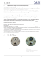
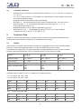
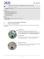
TL - TE
TL - TI
User Manual
TL - TE / TI
Contents
1
1.1
1.2
1.3
1.4
2
3
4
4.1
5
5.1
5.2
5.3
6
6.1
7
7.1
7.2
7.3
8
9
9.1
9.2
9.3
9.4
9.5
9.6
10
10.1
10.2
10.3
10.4
10.5
11
11.1
12
13
14
14.1
15
16
17
18
General
Information to the user manual
Limit of liability and warranty
Disposal
Scope of delivery
General advice and safety regulations
Application range and functional principle
TL-TE
-TE / TI Series
Features Series TL
Technical Data
Optics
Technical data / Overview
Factory settings
Installation and initial operation
Preparation
Installation of the Pyrometer
Location requirements
Operating personal requirements
Mechanical installation
Initial operation of the pyrometer
Operation and parameter adjustment
Controls and connections
Emissivity settings (EMI)
Preliminary note
Examples with emissivity corrector (TL-TE)
Emissivity settings with handheld
ld configuration tool (TL-Tl
-Tl only)
Emissivity settings with AT - 301 USB and PC (TL-Tl
-Tl only)
Further parameter settings (only for TL-Tl)
-Tl
-Tl)
Preliminary notes response time
Response time settings with handheld
ld configuration tool
Response time settings with AT - 301 USB
Sub-range settings with handheld
ld configuration tool
Sub-range settings with AT - 301 USB and PC
Adjustment of clearing time of maximum value storage with
handheld
ld configuration tool
Adjustment of clearing time of maximum value storage with
AT - 301 USB
Adjustment of ambient temperature with handheld
configuration tool
Overview of adjustable parameters for TL-Tl
-Tl
Appendix
Technical Background
Technical terms index
Physical basics
Accessories for TL-Series
Copyright
1
1
1
1
2
2/3
4
4
29
5
5
5
9
9
9
10
10
10
10
11
13
13
14
14
15
40
40
15
16
16
16
16
16
16
17
42
17
42
17
43
18
18
18
18
20
211
21
TL - TE / TI
1
General
1.1
Information to the user manual
We are pleased that you have decided to buy our CALEX TL device.
You now dispose of a pyrometer of high quality for industrial use.
Please read this manual carefully and step for step including all notes to security, operation and
maintenance before using the pyrometer. For operation of the instrument this manual is an
important source of information and work of reference. To avoid handling errors keep this manual
in a location where you always have access to.
All notes – especially safety notes – are to consider.
Should you require further assistance, please call our customer service hotline in
Leighton Buzzard, England : 0044 (0) 1525 373178.
1.2
Limit of liability and warranty
All general information and notes for handling, maintenance and cleaning of this instrument occurs
to the best of our knowledge under consideration of our know-how.
CALEX is not liable for any damages that arise from the use of any examples or
processes mentioned in this manual or in case the content of this document should be
incomplete or incorrect. CALEX reserves the right to revise this document and to make changes
from time to time in the content here of without obligation to notify any person or persons of such
revisions or changes.
All series TL instruments from CALEX have a warranty of two years from
the invoice date. This warranty covers manufacturing defects and faults
which arise during operation only if they are the result of defects caused by
CALEX. This warranty is void if the instrument is
disassembled, tampered with, altered or otherwise damaged, without prior
written consent from CALEX.
After the period of warranty in case of repair we grant 12 months warranty
for all spare parts. The warranty does not include electrical fuse, batteries
and parts which were use by mistake or were destroyed. Self-inflicted
failure like wrong handling, changing or rebuilding the device, hard
mechanical effects are not covered by guarantee and have to be taken over
by the user. Opening the device will also cause a loss of guarantee.
1.3
arranty
W
24 Months
Disposal / Evironmental protection (in accordance with RL2002/96/EC)
The lens or their coating may contain hazardous materials which are of
no danger following the intended usage. You are not allowed to dispose the
device to electronic waste.
The unit may not be disposed of with normal household waste
but must disposed of in accordance with environmental regulations.
1
TL - TE / TI
1.4
Scope of delivery
CALEX TL with optics as chosen and with emissivity corrector (TL-TE)
or service interface (TL-Tl); connection cable 2m; 1 Inspection sheet A5; 1 User manual
2
General advice and safety regulations
Intended usage
This device is only for non-contact temperature measurement. If you use the pyrometer not compliant to the description in this user manual it may cause loss of all guarantee claims against the
manufacturer.
General source of danger
Using the pyrometer with the optional laser pilot light means that it is seen as a
laser device class 2 following IEC 60825-1-3-4 regulations.
Responsibility of user
As long as the device was in technical perfect conditions after delivery (please refer to inspection
sheet with signature and stamp), the responsibility for correct handling will be by the user. For
eventually property damage or personal injury producer liability is impossible. This is only not valid
in the case a verifiable mistake happened by the producer is assessable.
Who can use and maintain the pyrometer?
Using the pyrometer is restricted to qualified personnel which has got instructions before initial
operation and handling. Instructions should be by a supervisor or by staff of CALEX
customer service.
Personal protective equipment (only for using laser pilot light)
Following European regulation EN 60825 devices are grouped into 5 categories after their radiation efficiency and irradiance. The higher the number the more is the possible danger. Working with
TL-TE/TI
-TE/TI means laser category 2. Laser category 2 says that the natural lid closing reflex gives
enough protections against this laser radiation.
ATTENTION: Do not look directly into the radiation ray!
You have to wear laser protection glasses if using a laser pilot
light. If you are aware looking into the laser ray for a long time it
may cause damages to your eyes. Devices of laser category 2 can
cause a glare which may leads to other incidents. You should take
care not to use laser devices against their intended usage. For further
information please refer to a publication of the radiation protection commission called
„Danger through laser pointer“,Bundesanzeiger Nr. 144, 6.8.1998.
ATTENTION:
You have to wear laser protection glasses if using a laser pilot
light.
2
TL - TE / TI
Safety arrangement
The operation of the pyrometer is only allowed with an extra-low voltage protection of 24V DC.
This voltage does not cause hazards to health and life of the user.
How to prepare your desk before starting the operation
All desks should be according to ergonomic standards and national regulations. For construction
or fixing the pyrometer please refer to chapter 7.3. Handling the device has to be
according to technical data under 5.2.
Prohibition of changing or rebuilding the device on your own
It is strongly prohibited to do technical changes to the device as long as you do not have
permission by the manufacturer. Contravention to this means the manufacturer will not take over
liability caused through damages. It automatically will cause loss of all guarantee claims against
the manufacturer.
Maintenance and care
The device does not need any maintenance accept the lens. A slight pollution of the lens can be
cleaned by using dry and oil free compressed air. For heavy pollution please use a soft and dry
tissue.
ATTENTION:
Do not clean the lens with acidic or solvent based fluids.
The germanium lens of TL-TE
-TE 14 and TL-Tl 14 (8...14 µm
spectral range) has a slightly colored blooming coat you are not
allowed to remove. It will cause measuring errors.
Packaging
Best case to transport or ship the pyrometer is using the original packaging. If not available,
please find a shock-proof package. For overseas shipment or long term storage in rooms with
high humidity you should heat seal the pyrometer to protect it against humidity. Please also
protect the optics with a protection cover (as delivered) or a plastic.
Usage of symbols and emblems
Please refer to the symbols and emblems used in this manual:
This symbol warns for general threads or dangerous places.
This symbol warns when it is about a laser device of European
standard IEC 60825-1-3-4.
Tip:
This emblem in a grey box means, we offer you an animation to solve
the described situation in an easy way.
Advice: When you see the emblem „Advice“ in a grey box we offer useful
advice for appropriate handling of the device.
3
TL - TE / TI
3
Application range and functional principle
The compact CALEX TL series is especially designed for industrial use. With the solid body in
stainless steel housing and the large variety on optics with fixed focus it is applicable in nearly all
industrial areas. Several standard measuring ranges are available.
The TL-TE/TI 14 is applicable for measurements on non-metallic or coated metallic surfaces,
the TL-TE/TI
-TE/TI 5 especially for measurements on glass surfaces. The TL-TE/TI 4 is designed for
measurement in flame heated ovens due to its special spectral range.
The infrared radiation of the measured object will be displayed on a detector and transferred in an
electrical signal. This signal will be digitally processed and transferred in the standard temperature
linear signal of 4 ... 20 mA. It can be easily integrated in existing measuring and controlling
systems. Both wires of a two-wire-device will be used simultaneously for power supply and
transmitting of the measuring signal.
Thanks to the emissivity corrector on the rear side of the device (TL-TE) the emissivity factor of
the appropriate material can be adjusted easily. Several default sub-ranges can be
factory-adjusted within standard measuring ranges. Instead of the emissivity corrector TL-Tl is
equipped with a service interface.
Emissivity, sub-range and response time of the device IKS-TI can easily be setup by connecting
the handheld
configuration tool or the AT - 301 USB to the interface. Adjusting the parameters with TL-Tl
-Tl works
with the software INFRAControl coming along with the interface. By connecting the pyrometer via
TL-Tl to a PC/ laptop it is galvanically separated.
The device can be equipped with different optics due to application requirements. The TL devices
will be delivered with plug connector by default.
The robust design as well as the wide range of accessories guaranty high operational reliability
even at rough environmental conditions.
4
TL - TE / TI Series
TL-TE
-TE with emissivity corrector
TL-Tl
-Tl with service interface
to connect to
the handheld configuration tool
or the AT - 301 USB
4
TL - TE / TI
4.1
Features SeriesTL
►Measuring non-metallic or coated metallic surfaces (TL-TE/TI 14 from -32 to 900°C),
TL-TE/TI
-TE/TI 5 (100 to 1200°C) especially for measurements on glass surfaces,
TL-TE/TI 4 (300 to 1000 °C) is designed for measurement in flame heated ovens due
to its special spectral range.
►digital internal measurement value processing
►Output 4 ... 20 mA temperature linear, ohmic resistance max. 700 Ohm at 24 V
►Sub-ranges: TL-Tl: via interface adjustable, minimum span 51 °C, TL-TE:
sub-range please refer to 5.2.
►Response time t90 from 100 ms, adjustable up to 10 s
►Emissivity ε: 0,2 ... 1,0 adjustable at device (TL-TE) or via the handheld
configuration tool or the AT - 301 USB (TL-TI)
5
Technical Data
Below you will find the description of optical, thermal, electrical and physical features of the
models (technical details are subject to be changed without notice).
5.1
Optics
Depending on customer requirements the device is equipped with one of the following optics.
Later you cannot exchange that optics. You have to define them at your order.
Pyrometers work passively. The pyrometer takes infrared radiation via its lens from a certain
spectral range and transforms it with its infrared sensor into an electrical signal.
Product:
TL-TE 14
TL-Tl 14
TL-TE 5
TL-Tl 5
TL-TE 4
TL-Tl 4
Measuring range:
-32... 900 °C
100... 1200 °C
300... 1000 °C
Spectral range:
8 ... 14 µm
5.14 µm
3.9 µm
Distance /spot size
50 : 1
40 : 1
40 : 1
Optics: (see table below)
100
300
800
100
300
1200
100
300
1200
Standard optics, details in mm, a = distance, M =measuring field
3.9 µm optics 100, 300, 1200
5.14 µm optics 100, 300, 1200
Optics
a1
M1
a2
M2
a3
M3
100
100
2.5
200
18
300
35
300
300
6
600
22
1000
45
1200
1200
24
2500
50
4000
80
8-14 µm optics 100, 300, 800
100
100
2
200
18
300
35
300
300
6
600
22
1000
45
800
800
16
1500
36
2500
68
5
TL - TE / TI
Tip:
The measured object can be at any distance but it has to be bigger or
at least as big as the spot size at measuring distance.
The following graphs give an overview about the spot size (in mm) dependent of the distance
(a in mm) (gap to the neck in the graph) Available optics for models TL-TE 14 and TL-Tl 14 :
TL-TE 14
TL-TI 14
TL-TE 14
TL-TI 14
TL-TE 14
TL-TI 14
Available optics for models TL-TE 5, TL-TE 4,TL-Tl 5 and TL-TI 4:
TL- TE 4/5
TL-TI 4/5
TL- TE 4/5
TL-TI 4/5
TL- TE 4/5
TL-TI 4/5
The spot size diameter M=15 mm at a measuring distance 0 is according to aperture (diameter of
aperture) of the optics.
6
TL - TE / TI
As you can see in this figure the spot size M is depending on a change of the measuring distance
a. The calculation to the interim values can be determined by the following formula:
Depending on the distance of the measured object (smaller or bigger than measuring distance)
you should chose the appropriate formula (see grey box next side).
Example:
Given:
TL-TE 4 with Optics 100
Aperture = 15 mm
(diameter of aperture → data sheet)
a = 100 mm
(measuring distance → data sheet)
M = 2.5
(spot size → data sheet)
Sought after:
spot size in 70 mm and 250 mm distance (the object
going to be maesured has to fill completely the size ot the measuring
field).
Result:
spot size at 70 mm: (distance is smaller than measuring distance of 100 mm
please use appropriate formula)
M = 70 mm / 100 mm (2.5 mm - 15 mm) + 15 mm
M = 6.25 mm
Spot size at 250 mm: (distance is bigger than measuring distanca of 100 mm, please use
appropriate formula)
M = 250 mm / 100 mm (2.5 mm + 15 mm) - 15 mm
7
TL - TE / TI
5.2
Technical Data Overview
Type:
TL-TE 14
(with emissivity corrector)
TL-Tl 14
(with service interface)
TL-TE 5
(with emissivity corrector)
TL-Tl 5
(with service interface)
TL-TE 4
(with emissivity corrector)
TL-Tl 4
(with service interface)
Measuring range:
-32...900°C
100...1200°C
300...1000°C
Spectral range:
especially for
measurement on:
8...14 µm non metallic or
coated metallic surfaces
5.14 µm glass surfaces
3.9 µm flame heated
ovens
Optics (material):
Germanium (Ge)
ZnS
ZnS
Noise equivalent
temperature
difference:
a = 1, t = 1
at t90= 120 ms: 0,2°C
at t90=1s: 0,05°C
(at 23°C
measuring temperature)
at t90= 120 ms: 0,15°C
at t90= 120 ms: 0,1°C
(300°C/1100°C
measuring temperature)
at t90= 120 ms: 0.6°C
at t90= 120 ms: 0.2°C
(500°C / 900°C
measuring temperature)
Scope of
delivery:
TL-TE 14 with emissivity
corrector
TL-TI 14 with service interface
TL-TE
-TE 5 with
emissivity corrector
TL-Tl
-Tl 5 with service
interface
TL-TE 4 with
emissivity corrector
TL-TI
-TI 4 with service
interface
TL-TE/TI, inspection sheet, user manual,
Connection cable is not part of scope of delivery
Sub-range:
TL-TE 14: -32...200°C/ 0...100°C/ 0...200°C / 0... 300°C/
0...500°C/0...750°C/ 0...1000°C
TL-TE 5: 100...1200°C (other sub ranges on request)
ITL-TE 4: 300...1000°C (other sub ranges on request)
TL-Tl: adjustable via service interface, minimum span 51 °C
Data handling:
Digital
IR detector:
Thermocouple
Power supply:
24 VDC ± 25%, ripple < 0,5 V
Analogue output:
4...20 mA temperature linear, load-independent direct current
Load:
max. 700 Ω at 24 V (max. 200 Ω at 18 V)
Interface:
Service-Interface for connection with interface AT - 301 USB or Handheld configuration
tool (TL-Tl)
Parameters:
(adjustable)
TL-TE: Emissivity ε
TL-Tl: Emissivity ε, response time, sub-ranges (within measuring range), clear time of
the peak piker mode, °C/°F - option, possibility to enter ambient temperature
Working
temperature:
0 ...+70°C
Storage
temperature:
-20 ... +70°C
Emissivity ε:
TL-TE: 0.2... 1 adjustable on the emissivity corrector at the rear of the unit
TL-TI: adjustable via AT - 301 USB or by using the Handheld configuration tool and PC in
steps of 0.01 (using the INFRAControl software)
Response time:
100 ms... adjustable up to 10 s by Service-interface (TL-TI)
Accuracy:
1% + 1 K of measuring value at ε = 1 and 23°C ambient temperature
Repeatability:
< 0.5 % of measuring value
8
TL - TE / TI
Protection class:
IP 65/DIN 40050
Weight:
410g
Dimensions:
Thread M 40 x 1,5; length 138 mm
Test base:
EN 55 011: 1998, limit class A
CE-Symbol:
Corresponding to EU regulations
Accessories for TL
T -TE
(with emissivity corrector)
Mounting angle fixed, mounting angle adjustable, power supply,
cooling jacket, air purge unit, laser pilot light unit, connecting
cable extension, digital display
Accessories for TL-Tl
(with service interface)
same as TL-TE,
additionally: digital display, interface AT - 301 USB, Handheld
configuration tool and software INFRAControl
5.3
Factory settings
The emissivity is preset ex works to ε = 1. Response time is preset to 100 ms. For devices with
service interface the sub-range is the same as the measuring range. Devices with emissivity
corrector can be preset with sub-ranges as mentioned in 5.2.
Settings due to customer‘s specifications are possible on request.
6
Installation and initial operation
6.1
Preparation
The pyrometer position and the respectively adjustable parameters are determined from the
application. Concerning the pyrometer position please take care of ambient temperature,
atmospherical conditions and potential occurrence of electromagnetic interferences.
If the installation of an air purge unit is intended the according supply of compressed air (pressure
0.2 bar) needs to be provided. Please take also care of the cable route concerning the connection
of AT - 301 USB interface tool and potential PC with USB interface when planning your installation.
Ambient temperature:
The influence of high ambient temperatures must not exceed the working temperature of
0 to +70°C. Otherwise wrong measuring results may occur or the pyrometer might be damaged.
The influence of high ambient temperatures can be minimized by using appropriate accessories
(e.g. cooling jacket).
Atmospherical conditions:
Smoke, dust, steam or other air contamination as well as soiled optics are a problem for noncontact temperature measurement. The Pyrometer can not collect enough infrared energy for an
exact measurement and so measuring errors will be the result. An air purge unit (see accessories
page ) can be helpful to antagonized heavy pollution of the optics.
9
TL - TE / TI
Electromagnetic interferences:
The CALEX TL has passed the test for CE-symbol according to EU regulations. Any interferences
beyond may affect proper functionality of the pyrometer!
To protect the device from electromagnetic interferences the following methods are established:
The device should be mounted as far as possible from potential sources of interferences, e.g.
machine parts with electrical motors which may produce interference peaks. Use shielded cables
for all connections. Make sure that shield is grounded properly.
7
Installation of the Pyrometer
7.1
Location requirements
7.2
Operating personal requirements
The TL should be mounted on a stable, solid surface. According to the dimensions of M 40 x 1.5
at a length of 138 mm it can be mounted everywhere by taking the requirements mentioned
into consideration .
Ergonomy and occupational health and safety directives should be considered to assure a secure
operation with the pyrometer.
It is recommended to use the designated accessories for mounting of the device
(see accessories)
The installation should be done by qualified operating personal.
Advice:
7.3
We only recommend qualified personal to operate the pyrometer.
The manufacturer will not cover damages caused by improperly
installation or non-qualified operating personal.
Mechanical installation
An existing mounting angle should be installed first. The Pyrometer can be easily installed now as
illustrated in the next figure .
1.
2.
3.
Loosen the ring nut
Attach mounting angle
Tighten the ring nut
Cable routing
Besides the mentioned requirements to location and operating personal the distance from
pyrometer to power supply unit should also be kept in mind. Do not use a cable length with more
than 100 meters for power supply.
10
TL - TE / TI
Adjusting the pyrometer
The adjustment of the device is depending on pyrometer configuration.
Thermal adjustment:
Pyrometer without laser pilot light can be adjusted with visual judgement to the object being
measured. A precise adjustment can be done for example by a digital display integrated in the
current output. The pyrometer is adjusted if the maximum temperature is displayed.
Laser pilot light:
Pyrometers with laser pilot light (accessory) can be done easily adjusted by aiming the measuring
object surface with the visible red light laser. The centre of the laser is also centre of the
measuring field.
Tip:
Please consider measuring distance to avoid other parts be included in
measuring field. Otherwise measuring errors may occur.
8
Initial operation of the pyrometer
Please remove the yellow protection cap at the front end of the pyrometer.
Connecting the power supply
The TL need power supply of 24 V DC ±25%. Please put the connecting cable in the 2-pin flange
plug at the rear side of the pyrometer (see next figure) and connect the other end of the cable to a
24 V DC power supply.
Advice:
The Pyrometer is equipped with inverse-polarity protection.
Connecting cable for power supply
has to be connected with 2-pin flange plug
at the rear side of the Pyrometer.
Figure: Pyrometer rear side
Polarity is important when connecting the Pyrometer with power supply (see next figure). The
white cable (+) has to be connected with „+“ and the brown cable (-) has to be connected
with „-“ connecting terminal.
The current consumption is an indicator for measuring temperature and also the measuring signal
(2-wire-device).
Tip:
The device is ready for operation right after connecting the power
supply. A balance to ambient temperature should be waited for.
11
TL - TE / TI
Attention:
Operation of the Pyrometer is allowed only in mentioned power
supply limits of 24 V ± 25%.
+ white
- brown
Shielding (black)
white
brown
black
4 ...20 mA
LED Display
with external
Power supply
+24 V
0 V
Shielding
- +
24V DC
Power supply 24 V DC
Figure: power connecting
Additional devices such as digital display to process the output signal of 4 ... 20 mA can be
integrated in the current loop. Please be advised that the maximum load must not exceed
700 Ω at 24V DC.
Tip:
Additional devices, e.g. controller can be connected in-line with
display corresponding to connecting plan.
To meet the requirements of electromagnetic compatibility all connecting cables should be
shielded.
The shield of a two wire connecting cable is usually connected at pyrometer side only. At cable
extensions the shield has to be extended too. At the power supply side the shield is not connected
to avoid ground loops.
Tip:
If the device is grounded over mounting side the shield has to be
left open. Otherwise always ground the pyrometer.
12
TL - TE / TI
Tip:
Formula for calculation of temperature from current value
Displayed current value - Current min x (End of Meas. range - Start of Meas. range) + Start of Meas. range
Displaye
Current max - Current min
Example:
Displayed current value: 8 mA
Start of measuring range: - 32°C
End of measuring range: 900°C
Current min: 4 mA
Current max: 20 mA
Result:
8 mA - 4 mA
20 mA - 4 mA
x (900°C - (-32°C) ) + (-32°C) = 201°C
9
Operation and parameter adjustment
9.1
Controls and connections
The operating controls and connections are located at the rear side of the device as shown the
next figures.
Sealing screw
Underneath this sealing screw depending on type of
device you can either find the emissivity corrector (TL -TE)
or service interface (TL-Tl) for connection of the optional
AT - 301 USB interface tool or Handheld configuration tool .
Plug connector
The 2-pin plug connector is for power supply and transfer
of the measuring signal 4 ... 20 mA (2-wire-device).
Emissivity corrector
With the emissivity corrector the emissivity is manually step
less adjustable within the range of ε = 0.2 to 1.
13
T - TE / TI
TL
Service interface
The service interface is for connection of AT - 301 USB
interface tool or the handheld configuration tool to adjust
emissivity, subranges, response time or graphical analysis
(only for AT - 301 USB via PC with evaluation software).
Handheld configuration tool: Following parameters are
adjustable: sub-range, emissivity, response time, clear time
of the peak piker mode, C/°F unit.
AT- 301 USB: Following parameters are adjustable:
sub-range, emissivity, response time, clear time
of the peak piker mode, C/°F unit.
The evaluation software INFRAControl allows graphically
evaluation of measured data and parameter adjustment
via USB interface as well. The software is accompanying
AT- 301 USB.
9.2
Emissivity settings (EMI)
9.3
Preliminary note
Only the exact knowledge of emissivity ε (epsilon) of measuring objects and the appropriate
adjustment on pyrometers can guarantee exact temperature measurement.
The emission coefficient ε is the relationship of the emission output of an object to the
emission output of a black body radiation source at the same temperature.
The emission coefficient ε for a black body at all wave lengths is 1.
The emissivity depends on the material being measured and its value is always between 0 and
1 (0...100%). At ε=1 a body absorbs all incoming infrared radiation. It is called „black body“. The
more radiation is reflected by the surface of the body, the smaller the emissivity and an
appropriate adjustment needs to be done (with emissivity corrector TL-TE) or with service
interface TL-Tl).
To find out correct emissivity a comparison measurement should be done as described below:
1.
You can measure the temperature with a contact thermometer. Now adjust emissivity on
pyrometer until the temperature value is equal to the value measured with the contact
thermometer.
2.
You can paint an area on the measuring object (if possible) with black carbon or
lacquer. This gives a high emissivity (ε = 0.95) and reaches the same temperature
value as the material below. You can now measure next to the blackened area and
adjust the emissivity until the same temperature value is reached.
Advice:
The lower the emissivity of a material the bigger the measuring
errors might be!
9.4
Examples with emissivity corrector (TL-TE)
(TL-TE
The emissivity corrector can be adjusted by using a small screw driver.
Adjust the emissivity of the material being measured by turning the emissivity corrector to the
specified value.
14
TL - TE / TI
Example: TL-TE
-TE - spectral range 8...14 µm
ε = 0.90 (90%)
ε = 0.75 (75%)
(measuring object cement)
9.5
(measuring object graphite)
Emissivity settings with the handheld configuration tool (TL-Tl only)
For more details than here please refer to the handheld configuration tool user manual handed out
to you separately.
The handheld configuration tool is available as accessory for TL-Tl. It allows adjusting
parameters like emissivity response time and sub-ranges individually on site.
1.
The handheld configuration tool will be connected with service interface (see handheld
configuration tool manual).
2.
Choose the parameter „emissivity“ in the menu of the handheld configuration tool.
3.
Adjust desired emissivity with cursor buttons up [↑] or down [↓] , in steps of a
thousandth part in between 0.200 to 1.0
4.
Push ENTER to confirm settings.
9.6
Emissivity settings with AT - 301 USB and PC (TL-Tl only)
For detailed description of all features and settings please do also refer to software manual
included in scope of delivery of AT - 301 USB.
Next figure : Software INFRAControl
After connecting your AT - 301 USB and clicking the button „log on device“ the start up screen
(next figure) will be displayed. The emissivity can be set by clicking the arrow-keys in the panel
„Parameters“. It is also possible to type in the desired emissivity directly in the description field.
The emissivity value will be transferred to pyrometer by hitting the „ENTER“ button.
Figure: Software INFRAControl
15
TL - TE / TI
10
Further parameter settings (only for TL-Tl)
-Tl
-Tl)
10.1
.1
Preliminary notes response time
The response time is the time span between
an erratic change of measuring signal and
time from which the Pyrometer output signal
is within specified limits. This time refers
to 95% of measuring signal skip.
Figure: Response time
NOTE:
The adjustment of response time and sub-ranges is not possible at
pyrometers with emissivity corrector! This parameter is adjusted
ex works on delivery.
10.2
Response time settings with the handheld configuration tool
1.
2.
3.
4.
The handheld configuration tool will be connected with service interface.
Choose the parameter „response time“ in the menu of the handheld configuration tool .
Adjust desired response time with the given values.
Push ENTER to confirm settings.
10.3
Response time settings with AT - 301 USB
The desired response time can be chosen in the panel „Parameter“ (see figure response time) by
clicking the appropriate list box. The new value will be send to the pyrometer immediately.
10.4
Sub-range settings with the handheld configuration tool
1.
2.
3.
4.
The handheld configuration tool will be connected with service interface.
Choose the parameter „sub-range“ in the menu of handheld configuration tool .
Adjust desired sub-range with cursor buttons [↑] up and [↓], down (lowest and highest
value).
Push ENTER to confirm settings.
10.5
Sub-range settings with AT - 301 USB and PC
The desired sub range can be set by typing the temperature values in the appropriate description
field in the panel „Parameter“. The subrange cannot exceed the measuring range of the pyrometer
shown in the status bar. The minimum sub-range span is 51 °C. The lower sub-range value
corresponds to 4 mA current output and the upper sub-range value corresponds to 20 mA. The
values will be transferred to the pyrometer by clicking the button „apply“.
Preliminary note clearing time of maximum value storage:
The maximum value store saves the highest measurement taken during a reading. You can
program the amount of time that the stored value will be held and displayed, before it is deleted
and replaced by a new value.
16
TL - TE / TI
This feature is particularly useful when: fluctuating object temperatures cause the display or the
analogue outputs to change too rapidly, or the pyrometer is not constantly viewing an object to be
measured. In addition, it may also be beneficial to periodically delete and reset the stored max. or
min. values.
The device uses a so called double storage. This mode utilizes two memories in which the highest
measured value is held and is deleted alternately in the time interval set (clear time).
The other memory retains the maximum value throughout the next time interval. The
disadvantages of fluctuations in the display with the clock frequency are thereby eliminated.
The following settings are possible:
1.
Clear time „off‘: the storage is switched off and only momentary values are measured.
2.
If any clear time is set, the maximum value is estimated and held in double storage
mode. After the entered time (in seconds) the storage will be deleted.
3.
The „auto“ mode is used for discontinuous measuring tasks. For example objects are
transported on a conveyer belt and pass the measuring beam of the pyrometer only
4.
for a few seconds. Here the maximum value for each object has to be indicated. In
this mode the maximum value is stored until a new hot (or cold) object appears in the
measuring beam. The temperature which has to be recognized as „hot“ is defined by the
low limit of the adjusted sub range. The stored maximum value will be deleted when the
temperature of the new hot object exceeds the low limit of the sub range by 1% or at least
2°C. If a lower limit is not entered, the maximum value storage will be deleted whenever the
lower level of the full measuring range has been exceeded.
11
1.
2.
3.
4.
11.1
Adjustment of clearing time of maximum value storage
with handheld configuration tool
The handheld configuration tool will be connected with service interface.
Choose the parameter „maximum value storage“ in the menu of handheld configuration tool.
By using the arrow buttons you can choose between the mode „off‘, „auto“ and setting of the
given values. Please refer to the preliminary note for more details.
Push ENTER to confirm settings.
Adjustment of clearing time of maximum value storage with
AT - 301 USB
The desired clearing time of maximum value storage can be set in the appropriate description
field in the panel „Parameter“. By using the arrow buttons you can choose between the mode „off‘,
„auto“ and setting of the given values. Please refer to the preliminary note for more details. The
new value will be send to the pyrometer immediately.
12
Adjustment of ambient temperature with
handheld configuration tool
The ambient temperature can be adjusted within the borders of the whole measuring range.
An automatic adjustment of ambient temperature can be chosen using the inner temperature of
the pyrometer as reference.
The ambient temperature is especially important if the measured object has the same temperature
or is colder as its ambiance (e.g. measurements at room temperature). This parameter helps to
compensate effects of reflection.
17
TL - TE / TI
13
Overview of adjustable parameters for TL-Tl
Parameter
Value
Emissivity:
Response time:
Clearing time:
Sub-range:
Ambient temperature:
stepless between 0.200 and 1.000
min, 0.5s, 1s, 2s, 5s, 10s, 30s
off, 0,1s, 0,25s, 0,5s, 1s, 5s, 25s, auto
maximum measuring range, minimum, subrange span is 51 °C
value within measuring range, automatically (internal temperature
of pyrometer)
°C, °F
Unit of measurement:
14
Appendix
14.1
Technical Background
Every body its temperature is above absolute zero (-273,15°C) it is emitting heat radiation. The
mean part of radiation contains wavelengths above visible, red light within infrared light.
CALEX Pyrometer are devices for temperature measurement to transform heat radiation via it`s
optics and the detector into an electrical signal. This electrical signal will be digitally
linearised and transformed into standardised analogue or digital output signals.
To keep measuring failures as little as possible it is necessary to choose a suitable spectral range by using different optical filters for each measuring object.
TL-TE 14, TL-Tl 14: 8...14 μm for measurement of non-metallic surfaces
TL-TE 5, TL-Tl
-Tl 5 : 5.14 μm for measurement on glass surfaces
TL-TE 4, TL-Tl 4: 3.9 μm for measurement in flame heated ovens
An integrated microprocessor in the pyrometer is responsible for digital signal processing for all
necessary calculating and saving. With the help of additional surrounding temperature
compensation the microprocessor allows an optimal measurement result.
TL-TE
-TE comes with an emissivity corrector to adjust emissivity between 0.2 and 1. TL-Tl is
equipped with an service-interface. The interface allows connecting the pyrometer via the
optional handheld configuration tool or the interface AT - 301 USB. T
The handheld configuration
tool and AT - 301 USB allow the user to adjust emissivity, sub-ranges and response time on their
own. The AT - 301 USB is connected via USB to PC/ Laptop and galvanically separated (!) to the
pyrometer. Accompanying the AT - 301 USB is the software INFRAControl which allows user
friendly handling to adjust emissivity, response time or measuring sub-ranges. You can also
adjust these parameters by using the handheld configuration tool. It comes additionally with a
temperature sensor to determine easily the emissivity of different material surfaces.
The pyrometer can be additionally equipped with a laser pilot light for precise aligning the
measured object. At high ambient temperatures it is common to equip the pyrometer with a
cooling jacket.
15
Technical terms index
The following technical terms lists important technical items concerning non-contact temperature
measurement.
18
TL - TE / TI
Absolute zero
Ambient
temperature
compensation
Air purge unit
Aperture
Aperture unit
Black body
Calibration certificate
calibration
calibration radiation
source
°C (Celsius)
Data memory
Detector
Emissivity
Focal point or focal
distance
Fixed optic
Fibre optics
pyrometer
Grey body
Intensity
Inspection
certificate
Laser pointer
Lens
Maximum value
storage
Measuring distance
Measuring object
Optics pyrometer
►-273.18°C. There is no molecular action at this temperature and
body‘s do not have thermal energy.
►possibility of correction by a device to gain higher accuracy in that
case the ambient temperature of the device is different to the
foreground temperature (reflected energy) of the measured object.
►accessory to keep the optics free of dust and other dirt
►opening of the shutter of an objective
►opening of aperture of an lens
►perfect radiation source which absorbs the whole impinge radiation
energy for all wavelength. For a real black body emissivity is 1 at all
wavelength.
►official calibration expertise by an calibration agency
►to measure accurately in comparison with international temperature
scale
►realising of a black body to calibrate pyrometers
►Temperature scale based on fix point 0° (zero degree) as freezing point
of water and 100° as evaporation point of water at normal pressure
°C = (°F-32) / 1.8
►to save measured data, allows to read out or analyse measuring values
►radiation receiver transforming heat radiation into an electrical signal.
►the emissivity is the ratio of reflected infrared energy of an object at a
certain temperature in a certain spectral range compared to the radiation
energy of a real black body with same temperature and spectral range.
For a real black body emissivity is 1 at all wavelength
►point or distance of the pyrometer at which the object is focussed to the
detector of the pyrometer and the optical resolution at its biggest.
►optic with fixed focal width without focus setting
►pyrometer with separated optical head which is connected via its fibre
optics cable to the measuring transformer
►body whose emissivity ε<1 is considered constant at all wavelengths
►radiation performance
►certificate about measurement uncertainty of a device
►accessory for exactly adjustment by using a laser as light source
►optical system consisting of one or more lenses or mirrors,
displaying the
measured object at the detector of the pyrometer
►accessory, saving the biggest measured temperature in a given and
adjustable time frame
►distance in-between measured object and lens leading edge of the
pyrometer
►object temperature is going to be measured.
►System to define temperature of a source by comparison with a
standard light source (usually with help of human eyes).
19
TL - TE / TI
Over-all radiation
Pyrometer
Ratio pyrometer
Reproducibility
RS232
RS485
Scanning optics
Spectral range
Spot size
Storage
temperature
Through lens
sighting
Transmission
wavelength
16
►pyrometer which is nearly sensitive to heat radiation in the whole
spectral range.
►instrument to measure temperatures without making contact with the
object to be measured (radiation thermometer)
►pyrometer using signals from two close to each other spectral ranges
and ratio formation to find out the temperature
►uncertainty to repeat a measurement value at same condition
►standardised serial interface for digital communication
►interface that allows higher number of receivers and senders at one wire
►equipment to re-direct the pyrometer radiation setting to a line vertical to
the optic axis, so that the surface of the object can be scanned. The
scanner moves the spot sizes across the object.
►area of spectral range which is used by the pyrometer when taking
readings
►area on the object from which the pyrometer receives most (90%)
of the signals
►ambient temperature to store and use the pyrometer correctly.
►optical accessory for accurate pyrometer adjustment
►the passing of radiation through a solid, liquid or gas; the transmission
coefficient gives the ratio between intensity of radiation that has passed
through, to the incoming radiation.
►describes the length of a wave between two points in a single phase
Physical basics
Above absolute zero (-237.18 °C) all bodies emit energy radiation in form of electromagnetic
waves. This radiation is often designated as thermal radiation or infrared radiation. The wavelength of the maximum radiation is moving towards visible area with rising temperature.
This can be found on glowing materials starting from deep red to yellow and finally to white glow.
Technical realisation of pyrometers
Pyrometers are complex systems containing optical, mechanical and electrical components.
A geometrical area (measuring spot) in a given distance of the object being measured will be
displayed on an infrared detector through the lens.
The adjustment of the pyrometer to the measuring object can be done with a pilot light or through
lens sighting.
The infrared detector changes the incoming radiation into an electrical signal. An afterwards
implemented electronics evaluates this signal into a linear temperature signal. Other parts like
display, maximum value storage or controller are suitable for further processing.
20
TL - TE / TI
17
Accessories for TL-Series
Cooling jacket, with air-purge and mounting
Air-purge
Mounting support, adjustable
Mounting support, fix
Vaccuum adapter
Laser pilot light unit
AT - 301 USB Interface tool with USB cable, software
Handheld
andheld configuration tool instrument for detection of emissivity, set up unit for
TL - instruments, temperature measurement with probes
18
Copyright
All rights reserved practicing industrial property rights. All rights reserved. Copying and publication
of this user manual or parts of it need previous allowance of CALEX Electronics Limited.
21
TL - TE / TI
Notes
22
Tel.:
Fax:
EMail:
Web:
0044 (0) 1525 373178
0044 (0) 1525 851319
[email protected]
http://www.calex.co.uk
v.01.07
CALEX Electronics Limited
PO Box 2
Harrmill Industria Estate
Leighton Buzzard,
Bedfordshire, England
LU7 4AZ