1
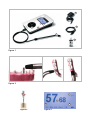
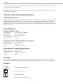
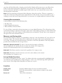
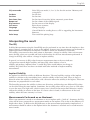
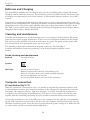
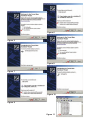
Osstell ISQ
USER MANUAL
5
1
3
6
2
4
7
Figure 1
Figure 2
9
8
10
Figure 3
Figure 4
11
English
Contents
Description
21
Indications for Use
21
Precautions
21
Technical Description/Specifications
22
22
Technical description
Specifications
Power, weight & size
Environmental conditions during transport
Environmental conditions during use
Accuracy
Symbols
Osstell ISQ Preparation and Set-up
Batteries
Setting the Time
Test Peg
Osstell ISQ Operation
22
22
22
22
22
22
23
23
23
23
23
23
23
23
24
24
24
Operation
Connecting SmartPeg
Performing a Measurement
Viewing Measurements
Memory and Saving data
Set-up Mode/Functions
Interpreting the result
The ISQ
Implant Stability
Measurements Performed on an Abutment
25
25
25
25
Batteries and Charging
26
Cleaning and maintenance
26
Computer connection
PC installation Checking the installation Firmware upgrade
Sending data to a PC
26
26
27
27
27
Service
27
Accessories & Spare parts
27
20
English
Figures
Figure 1. Osstell ISQ Instrument
1. Display
2. Blue LED Light
3. Operating Keys
4. Measurement Probe
5. Charger
6. PC USB Cable
7. Test Peg
Figure 2. Performing a Measurement
Figure 3. SmartPeg and SmartPeg-Mount
Figure 4. Instrument Display
8. ISQ value
9. Memory Position
10. Time and Date of Measurement
11. Battery Status
Description
Osstell® ISQ is a portable, handheld instrument that involves the use of the noninvasive technique,
Resonance Frequency Analysis for measuring dental implant stability. The system includes the use
of a SmartPeg™ attached to the dental implant or abutment by means of an integrated screw. The
SmartPeg is excited by a magnetic pulse from the measurement probe on the handheld instrument.
The resonance frequency, which is the measure of implant stability, is calculated from the response
signal. Results are displayed on the instrument as the Implant Stability Quotient (ISQ),
which is scaled from 1 to 100. The higher the number, the greater the stability.
Indications for Use
Osstell ISQ is indicated for use in measuring the stability of implants in the oral cavity and craniofacial region. Osstell ISQ can add important information to the evaluation of implant stability and can
be used as part of an overall treatment evaluation program. The final implant treatment decisions are
the responsibility of the clinician.
Precautions
The Osstell ISQ should not be used in the presence of explosive or combustible materials. The instrument probe emits magnetic pulses with peak strength of 20 Gauss, 9 mm from the tip. To avoid interfering with other equipment, the probe should not be held in close proximity to electronic devices. To
maintain a high level of safety, the power supply designed specifically for the Osstell ISQ must be used
21
English
when charging the instrument batteries. Additional power supplies must be ordered directly from
Osstell or your local distributor.
Caution: The measurement probe emits an alternating magnetic field that could potentially interfere
with cardiac pacemakers!
Technical Description/Specifications
Technical description
Osstell ISQ is CE-marked according to MDD in Europe. Osstell ISQ is constructed according to, and
fulfilling the standards EN 60601-1 (Class II, Internally powered, type BF applied part. Not AP or
APG equipment. Not protected against ingress of water.), EN 60601-1-2 and UL 2601-1. The symbols used, follow, to the extent possible, the European standard EN 60601-1, and the ISO-standards
9687 and 15223.
Specifications
Power, weight & size
Rated power: 5 VA, Type FW 7660M/05
Instrument size: 195 x 120 x 45 mm
Package size: 280 x 240 x 63 mm
Instrument weight: 0.4 kg
Gross weight: 1.0 kg
Environmental conditions during transport
Temperature: -40 ºC to +70ºC
Relative humidity: 10% to 95%
Pressure: 500 hPa to 1060 hPa
Environmental conditions during use
Temperature: Relative humidity: Pressure: IP-class: +10 ºC to +40 ºC
30% to 75%
700 hPa to 1060 hPa
IP20
Accuracy
ISQ accuracy is within +/- 0,5 ISQ units for a single SmartPeg. Including variations in the attachement torque and individual variations between different SmartPegs, the accuracy is +/- 2 ISQ units.
Symbols
i
Consult instructions for use
Class II Equipment
Type BF equipment
IP20
No protection against water
22
English
Do not re-use
Osstell ISQ Preparation and Set-up
Batteries
The internal battery is rechargeable and should be charged for at least 3 hours,
before its first use.
Setting the Time
Prior to the use of the instrument, the date and time should be adjusted (see set-up). The date and
time is stored when each implant measurement is performed.
Test Peg
The Test Peg included in the Osstell ISQ package may be used for testing and learning how to use
of the system. The Test Peg may be used as follows: Place the Test Peg on a table or hold it by hand.
Turn on the instrument and hold the measurement probe (See Figure 2) close to the top of the Test
Peg, until the instrument beeps and displays the ISQ value. The point to aim the probe tip at is
marked with red paint on the Test Peg.
Note: Do not remove the SmartPeg from the block!
Osstell ISQ Operation
Operation
To turn the instrument on, press any key. To turn it off, enter the setup menu by pressing the “centre”
key and press the arrow up or down keys until “Power off” is marked. Then press the centre key
again. In measurement mode, the instrument will power down automatically after 2-30 minutes (adjustable) of inactivity. To return to the measurement mode from the menu mode, press the left arrow
key.
The instrument is to be used with the probe connected to the instrument via its cable (Figure 1). The
probe with its cable can be autoclaved.
Note: Do not twist the connector when the probe is connected! To remove it from the instrument,
pull gently holding around the connector.
Connecting SmartPeg
SmartPeg should be handled carefully, as damages to the SmartPeg may affect the measurement
result. Connect the SmartPeg Mount to a SmartPeg (Figure 3). The SmartPeg is magnetic,
and the Mount will hold the SmartPeg as it is carried to the implant. Screw the SmartPeg onto the
implant or abutment. Use approximately 4-6 Ncm of torque. Do not over tighten, to avoid destroying the SmartPeg threads. The SmartPeg is disposable, and may be used for 10-20 attachments during
one patient’s session.
Performing a Measurement
Attach a SmartPeg to the implant or abutment. Hold the measurement probe close to the top of the
SmartPeg without touching it (Figure 2). Do not press any keys. When the instrument senses the
SmartPeg and the measurement is ok, it will emit an audible sound. If two such sounds are heard in a
23
English
row, they will be followed by a beeping sound and the Display will present one or two ISQ values.
If there is much electromagnetic interference noise present, the instrument might not be able to
measure. Instead it will emit an audible signal. If this is the case, try to remove the source of the
electromagnetic interference.
Note: Start by measuring in the mesio-distal direction (along the jaw-line). Then try to measure a
value also in the bucco-lingual direction (perpendicular to the jaw-line). If it is not possible to get a
reading in exactly the bucco-lingual direction, try to measure in a slightly different rotational angle.
Viewing Measurements
A measurement consists of the following data:
• The ISQ value
• Signal strength information
• Time and date of measurement
To view all data connected to the measurement, see set-up Mode/ Functions. The cell position of the
viewed measurement is showed in the upper right corner of the display. Change row and column with
the arrow keys. If the cell is empty, no measurement data is displayed. The Q-value is the strength of
the signal. The lowest allowed value is 1.
Memory and Saving data
The instrument memory consists of a spreadsheet, with rows 1-20 and columns A-T. One cell can be
viewed at a time. The viewed cell position is displayed in the upper right corner of the display (e.g.
A1 to T20). The data for each measurement is stored in a cell in the spreadsheet. The Set-up Menu
provides three methods for the storage of data:
Method 1 (default method): The data is stored in the first empty cell found
after the displayed cell, moving first by row, then by column. If no empty cell is
found at all, measurements have to be erased from memory.
Method 2: The ISQ is stored in viewed cell, regardless if it is empty or not.
Method 3: The ISQ is stored in the next row in the same column as the viewed
cell, regardless if it is empty or not.
Set-up Mode/Functions
To use the Set-up Mode, press the “centre” key. Menu selections are performed by highlighting the
row with the arrow up/down keys and pressing the “centre” key. The following table explains the
menu entries (They might differ dependent on Firmware version).
Function
Display data Erase ISQ Power off Displays additional data for the viewed measurement.
Erase the presented ISQ, a whole memory column or the whole memory.
Turn off the instrument.
24
English
ISQ save mode Set date Set time Pwr down time Beeper vol Disp contrast Quit menu
Language Host control
Pulse beep Select ISQ save mode (1, 2 or 3). See also the section “Memory and saving data”.
Set the date.
Set the time.
Set the time of inactivity before automatic power down.
Set the volume of the audible signals
Set the contrast of the display.
Exits the set-up menu.
Change language
Control Mode for sending data to a PC or upgrading the instrument firmware.
Turn on/off the pulsing beep.
Interpreting the result
The ISQ
Stability Measurements using the Osstell ISQ may be performed at any time after the implant or abutment is placed, assuming there is access to the implant. In most cases, measurements are performed at
implant placement and before the implant is loaded or before the abutment is connected.
The stability is measured at these time points to determine a change in stability. After each measurement, the ISQ values are recorded and used as the baseline for the next measurement performed. A
change in the ISQ value reflects a change in implant stability.
In general, an increase in ISQ values from one measurement time to the next indicates
a progression towards higher stability and lower ISQ values indicate a loss in
stability and perhaps, implant failure. A stable ISQ value would indicate no change in
stability. ISQ values have not been correlated with other methods of implant mobility
measurement.
Implant Stability
An implant has different stability in different directions. The total stability consists of the implant
stability in relation to the surrounding bone, and the stability of the bone itself. There is always a
direction where the stability is the lowest, and a direction where the stability is the highest. These two
directions are perpendicular to each other.
The SmartPeg measures the stability in those two directions, and therefore two different ISQ-values
can be achieved on the same implant. Sometimes, the two ISQ values will be very close to each other,
or even the same. The high value, which in most cases is found in the mesio-distal direction, mainly
reflects the stability in relation to the bone. If a lower value is found, it reflects more of the total
stability, where the bone anatomy is a factor.
Measurements Performed on an Abutment
When a measurement is made on an abutment or on an implant with a “built-in” abutment, the ISQvalue will be lower compared to a measurement made on the implant. This is due to the difference in
height above bone. To find out the ISQ difference to the measurement performed at implant level, a
measurement should be taken on the implant before the abutment is attached and a second measurement is made.
25
English
Batteries and Charging
The Osstell ISQ instrument must be charged using only the Osstell ISQ power supply. The charger
should be used in indoor dry locations. The instrument contains a Lithium battery. The battery symbol displays the approximate status of the batteries. A filled symbol indicates batteries are at 100%
capacity.
If the battery is completely discharged, the recharge process requires approximately three hours, depending on the room temperature. (Charging the battery in warm environments may require a longer
charging duration.) The power supply operates with mains voltage from 100 to 240 VAC, 50-60
Hz. Thus it can be used in most countries in the world using the appropriate mains adapter. Battery
charging is indicated by a flashing blue LED.
Cleaning and maintenance
If needed, the instrument may be cleaned using water or an isopropyl alcohol solution. The instrument does not require regular maintenance. In the event of an instrument malfunction, the Osstell
ISQ and accessories should be sent to the manufacturer for repair. The probe and the probe cable
may be autoclaved (over-pressurized steam, up to 135 deg C).
The SmartPeg is disposable and should be disposed of after use. The SmartPeg is
available with different connection geometries, to fit all major implant products on the
market.
Probe cleaning and maintenance
Method:
Symbol:
Warnings: Vacuum autoclave
135 º C
Do not exceed 135 deg C
Remove from autoclave directly after finished cycle
Allow to cool down before use, handle carefully when hot
Do not use dishwasher for cleaning
Do not pour fluids directly into any of the connectors
Computer connection
PC installation (fig 5-11)
When the instrument is connected to a PC, it is possible to upgrade the instrument firmware and/
or download measurement data from the instrument to the computer. To download data from the
instrument, the computer software “ISQ Data Manager” is needed. To install the instrument on
a computer, you will need the Osstell ISQ drivers. The drivers can be found on the CD that came
together with the Osstell ISQ instrument. It is also possible to download from www.osstell.com.
Connect the instrument to one of the USB ports in the computer. Use the cable that was included in
the kit. If the instrument is connected for the first time, the computer should automatically start the
Windows’ installation guide. Select the driver location when the guide is asking for it (Either the CD
or a place where you have stored the downloaded driver).
26
English
Even if the instrument is connected to a USB-port, it will appear as a “virtual” com-port in the
computer. The com-port will have a number, which may shift dependent on which USB-port the
instrument is connected to. If other hardware has been installed since last time the instrument was
connected, the com-port number could also change.
Checking the installation (Fig 12)
After the installation, you can check which com-port number the instrument uses in the computer.
You will need to know the port number when upgrading the firmware in the instrument. Open the
Windows Device Manager (see below) and view “Ports (COM & LPT)”. In the list of ports, it should
say “USB Serial Port (COM x)”, where x is the port number.
To open the device manager in Windows Vista: Right-click “Computer” and select “Manage” then
“Device Manager”.
To open the device manager in Windows XP: Right-click “My Computer” and select “Properties”
then “Hardware” and “Device Manager”.
To open the Device Manager in Windows 98: Right-click “My Computer” and select “Properties”
and then “Device Manager”.
Firmware upgrade
The instrument firmware can be upgraded. For the latest version, see www.osstell.com, where more
information is available. To upgrade the firmware, the instrument first has to be installed on a PC; see
section “PC installation”
Sending data to a PC
Measurements can be sent to the ISQ Data Manager, which is available for PC. To use the PC-program, the instrument has first to be installed on a PC; see section “PC installation”. For more detailed
instructions see ISQ Data Manager Users Manual or www.osstell.com.
Service
The instrument and accessories must be sent to the manufacturer for repair. Any
questions concerning this product should be referred to the manufacturer:
Osstell AB
Gamlestadsvägen 3B
SE-415 02 Göteborg
Sweden
Accessories & Spare parts
Spare parts and/or accessories should be ordered directly from the manufacturer or
from your local distributor.
27
Figure 6
Figure 5
Figure 8
Figure 7
Figure 10
Figure 9
Figure 11
Phone +46 31 340 8250, Fax +46 31 413 115. [email protected]
www.osstell.com
0402
Osstell AB 2009.02 © 25036-00 ML
Osstell AB Gamlestadsvägen 3B, SE 415 02 Göteborg, Sweden