1
Our Products are Inspired
LED CHASER
ASSEMBLY INSTRUCTIONS & TECHNICAL MANUAL
Saturday, 1 September 2012
C o m p u t e r I n s p i r a t i o n s • G e o r g e t o w n O N C a n a d a • w w w. c - i n s p i r a t i o n s . c o m
LED Chaser
LED Chaser Assembly Instructions & Technical Manual
Description
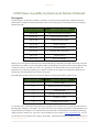
The LED Chaser is an animation controller for 32 LEDs. The current software implements 12 different animation
patterns that are settable via a three-position DIP switch. Seven of the patterns can be directly selected according to
the following table:
DIP SWITCH SETTING
A N I M AT I O N PAT T E R N
Off Off Off
Displays all 12 patterns sequentially.
On Off Off
Cylon/Knight Rider Scanner
Off On Off
Random Computer Lights
On On Off
Broadway Marquis
Off Off On
Two-eyed Scanner
On Off On
Snowfall with Accumulation
Off On On
Targeting Scanner
On On On
Binary Clock Display
When power is first applied to the LED Chaser, all the LEDs light up sequentially from right to left to help verify that
all the LEDs are working correctly. The rightmost LEDs corresponding to the current software revision light up next:
one LED for version 1, two LEDs for version 2, etc. The pattern associated with the current switch setting is displayed next in a continuously repeating cycle. With all switches off, all 13 patterns are displayed sequentially on a
rotating basis with each pattern active for about 10 seconds.
The additional five patterns that are not switch selectable (but are displayed with all switches off) are:
E X T R A PAT T E R N S
A N I M AT I O N PAT T E R N
0
Runway Lights
8
Double Scan with eyes moving out
9
Animated Sparks
10
Quadruple Scanner with four eyes
11
Fast Binary Counter
12
Double Scan to the Center
It is possible for any of these animation patterns to be assigned to the switches however you like provided you have a
MicroChip IDE, debugger, and compiler. The code for this board was developed using their free MPLAB X IDE V1.30
along with the XC8 C compiler V1.10. The LED Chaser board includes a standard PICKit-compatible programming/
debug connector at reference P2. The source code is available from our web site at www.c-inspirations.com. You can
also develop your own animations by creating a list of LEDs. The default times between animation steps can be set to
C o m p u t e r I n s p i r a t i o n s!
A s s e m b l y & Te c h n i c a l M a n u a l
1
LED Chaser
anything from 1 mS to about a minute. Any number of LEDs from one to 32 can comprise a
scene. However, the brightness of each LED decreases as the number of LEDs in a scene increases. See below for more details.
Assembling the LED Chaser Kit
Please verify that your kit contains the following parts:
1.
1.
2.
2.
3.
4.
5.
6.
7.
8.
9.
10.
11.
12.
13.
2 – 2.2 "F 16V ceramic capacitors
2 – 0.1 "F 50V ceramic capacitors
4 – 120 # ¼ W resistors
2 – 2K # ¼ W resistors (optional for future expansion)
4 – 10K # ¼ W resistors
1 – Right-angle 0.1” 6-pin header (optional for debug/programming)
1 – 3-position DIP switch
1 – 5V Regulator IC (MCP1702-5002E/TO)
1 – Preprogrammed microcomputer IC (PIC16F1829)
1 – 256Kbit EEPROM IC with I2C bus (24LC256P – optional for future expansion)
32 – 5mm red LEDs (or any color of your choice)
1 – Rectifier diode (1N4001)
1 – 9V battery clip
1 – LED Chaser PCB
1 – 9V battery (not included in kit)
Note: P3 is reserved for future expansion and is not included in the kit.
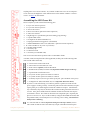
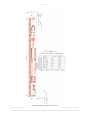
Assemble, solder, and clip the leads (where applicable) of these parts in the following order
(refer to PCB outline at the left):
4 – 120 # resistors located at R1 to R4.
4 – 10K # resistors located at R6, R8 – R10.
2 – 2K # resistors (optional) located at R5 and R7.
1 – Rectifier diode (1N4001) located at D33 (Important: banded end goes to the top).
1 – 3-position DIP switch located at S1.
2 – 2.2 "F 16V ceramic capacitors located at C2 and C3.
2 – 0.1 "F 50V ceramic capacitors located at C1 and C4.
1 – 9V battery clip at P1 (red wire goes to the square pad - pin 2 and black wire to pin 3).
1 – 5V Regulator IC (MCP1702-5002E/TO) at U1 (Important: flat end as shown).
If you have a volt meter handy, you could now perform a quick test to make sure the
power supply is working correctly. Connect the positive lead of the voltmeter to P2 pin 2
(square pad is pin 1) and the negative lead of the voltmeter to P2 pin 3. Attach the battery to the battery clip and you should see the voltmeter reading somewhere from 4.95 V
to 5.05 V. If not, please double check the soldered connections and make sure all parts
are oriented as shown. Also check for shorts between components pins—especially the
pins of U1 and C1 to C4. If you see the 9V battery voltage at the banded end of D33, then
the problem is likely a bad solder joint or U1 is missing or not working. Disconnect the
battery before continuing.
32 – 5mm red LEDs as marked (Important: notch goes to the top as shown) at D1 to
D32. Install one LED at a time and solder only one pin of the LED to hold it in place.
C o m p u t e r I n s p i r a t i o n s!
A s s e m b l y & Te c h n i c a l M a n u a l
2
LED Chaser
Then make sure the LED is flush on the PCB board. Reheat the soldered pin to seat the
LED properly—if needed. Solder the remaining lead and clip the excess pins. Repeat
this procedure for the rest of the LEDs.
1 – Right-angle 0.1” 6-pin header (optional) at P2 (if you’re going to develop your own
software or alter the existing software).
1 – Preprogrammed microprocessor IC (PIC16F1829) at U3 (Important: notch or dot
goes to the bottom as shown).
1 – 256Kbit EEPROM IC (24LC256P) (optional) with I2C bus at U2 (Important: notch or
dot goes to the top as shown).
Testing the Assembled Board
Once the components have been soldered to the PCB, test the assembly, preferably with a current-limited 9V power
supply or the battery.
1. Connect the +9V power supply lead to the 9V clip leads at P1 (positive to the red wire at pin 1 and negative to the
black wire at pin 3).
2. You should see all the LEDs light up in sequence starting from the top of the board. Then the top-most LED(s)
should light to indicate the firmware version programmed into the PIC microprocessor. Then, depending on the
DIP switch settings, the corresponding animation(s) should start playing.
3. You can change the DIP switch settings at any time. The new setting comes into effect as soon as the active animation has finished. If all the animations are playing, this mode is aborted whenever the active sequence has completed.
4. Trouble-shooting if no LEDs light:
a. Go through the power supply trouble-shooting list above.
b. Check all the soldered connections on U3 and resistors R1 to R4.
c. Verify that U3 is programmed by connecting a debugger and verifying the contents of the PIC’s memory are
correct.
5. Trouble-shooting if one or only a few LEDs don’t light:
a. Have all the required resistors R1 to R4 been installed and the solder joints are good?
b. Have all the LEDs been installed with the notch oriented correctly and the solder joints are good?
c. If you suspect one defective LED, apply about 2 V across each LED (notched side is ground) or use a 1K # resistor in series with the 9V power supply.
C o m p u t e r I n s p i r a t i o n s!
A s s e m b l y & Te c h n i c a l M a n u a l
3
LED Chaser
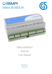
Technical Description
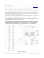
The circuit diagram below shows the LED Chaser schematic. Thirty-two LEDs are connected in a “Charlieplexed”
arrangement. A significant advantage of this LED organization is that fewer drive pins are required to handle more
devices than with any other technique. In this case, only eight processor pins are used to drive 32 LEDs. Actually
this circuit uses only a partial Charlieplex arrangement in order to minimize the number of current-limiting resistors.
A full Charlieplex configuration should be able to drive up to 42 LEDs using only seven processor pins. Traditional
multiplexing methods would require at least 12 pins. To protect the LEDs, the maximum current has been limited to
about 20 mA although some LEDs allow higher currents when pulsed. Since this design has a variable number of
LEDs on at a given time, the 20 mA maximum is advisable.
Switch S1 (consisting of three individual switches) selects the animation sequence to be displayed. Pull-up resistors
R8 to R10 provide a default level of logical 1 when a switch is open.
U1 is a linear regulator that provides the 5V supply for the microprocessor, U3. The debug/programming connector
at P2 is provided to allow user-specific changes to the software.
U2 is a 256 Kbit EEPROM that is reserved for future software implementations. It is intended to hold many more
animations than will fit into the PIC’s internal Flash. The expansion connector, P3, is also intended for future software additions that will allow multiple LED Chasers to be synchronized together to play a single animation.
LED Chaser Circuit Schematic.
C o m p u t e r I n s p i r a t i o n s!
A s s e m b l y & Te c h n i c a l M a n u a l
4
LED Chaser
LED Chaser Animation
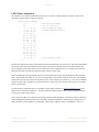
The simplest way to understand the animation process is to study an existing animation sequence. Below is the
“Random Computer Lights” animation sequence:
const uint8_t
4,
24,
4, 1,
3, 25,
12, 26,
6, 31,
20, 17,
10, 24,
22, 29,
5, 30,
22, 0,
19, 6,
26, 25,
4, 10,
21, 30,
29, 16,
2, 17,
8, 1,
};
Random[] = {
/*
/*
9, 15,
/*
8, 27,
/*
14, 11,
13, 2,
18, 23,
16, 19,
7, 21,
0, 28,
14, 5,
15, 20,
23, 9,
27, 18,
11, 3,
24, 13,
12, 31,
28, 7
/*
Play with four LEDs */
24 * 8 = 192 mS */
First animation frame */
Second animation frame */
Last animation frame */
The first byte indicates how many LEDs will be turned on simultaneously (four in this case). The second byte defines
the amount of time that each animation frame (groups of four bytes) is displayed (192 mS for this example). The
software displays each of the four LEDs in each animation for 96 mS and then moves on to display the next frame.
When the last frame is reached, the animation begins at the first frame again.
LEDs are numbered with 0 representing the top-most board LED (D17) and 31 representing the bottom board LED
(D16). Any number greater than 31 (e.g., 32) is not displayable so all the LEDs will be off in that case. This feature is
useful when you have four LEDs in an animation but only want to display one of them (e.g., 0, 32, 32, 32 would light
only the top-most LED). Repeating an animation frame is a simple way of slowing down just a portion of an animation for a special effect.
If you develop any animations that you would like to share, please email them to [email protected] with a
subject line of “LED Chaser Animation.” The best animations will be featured in future software updates and may
even be given a DIP switch position!
Note: Using more LEDs in an animation will cause the individual LED brightness to be reduced. This is a limitation
of the Charlieplexing technique used to drive the LEDs. Maximum brightness is achieved using a single LED. Two
LEDs would have ½ the brightness of a single LED. Three LEDs would have about & the brightness, and so on.
C o m p u t e r I n s p i r a t i o n s!
A s s e m b l y & Te c h n i c a l M a n u a l
5
LED Chaser
Mechanical Dimensions of the LED Chaser PCB
C o m p u t e r I n s p i r a t i o n s!
A s s e m b l y & Te c h n i c a l M a n u a l
6